Design of Core Clamping Arrangement for Transformersijaerd.com/papers/special_papers/ME061.pdf ·...
6
International Journal of Advance Engineering and Research Development Scientific Journal of Impact Factor (SJIF): 4.72 Special Issue SIEICON-2017,April -2017 e-ISSN : 2348-4470 p-ISSN : 2348-6406 @IJAERD-2017, All rights Reserved 1 Design of Core Clamping Arrangement for Transformers Mr.Vishal M. Solanki 1 , Mr.Dhaval V. Patel 2 1 Assistant Professor, Department of Mechanical Engineering, Sigma Institute of Engineering, Vadodara 2 Assistant Professor, Department of Mechanical Engineering, Nirma University, Ahmedabad __________________________________________________________________________________ Abstract:The research focuses on the development of particularmethodology for preparation of core of the transformer. Very high force is requiredto tighten the pressure bolts while preparation of the core, which is very difficult to applymanually. Hence some core clamping arrangement is to be developed, which reducesthe human effort.The issue regarding the clamping arrangement problem for the core has beensolved by developing large capacity C-clamp arrangement. __________________________________________________________________________________________ Keywords: C-Clamp, Core Frame, Core Preparation, Oil Filled Transformer, Transformer. I. INTRODUCTION Figure 1. Core Preparation Different width but same length steel sheets are placed one by one and the core isprepared. When the complete core is ready, core clamping frames are placed on position andthe bolts are tightened under pressure. As it require very large amount of force totighten the bolts, which is not possible to give manually. So when the clamp is used toapply force, it will be easy for the worker to tighten the bolt. The second difficulty is, there is a requirement of tightening 4 bolts on either side ona frame in a row. On tightening two bolts under pressure the plate will bend slightly, and there will be difficult for worker to tighten other bolts. An effective clamping arrangement is to be developed which can be used to apply alarge force to minimize the manual effort. It would be better if the existing resourcesof the industry are used while developing a clamping arrangement. II. LITERATURE REVIEW “Manual on Transformers”[1] contains complete criteria to design the transformer according to various Indian Standards. This book is very useful for transformer design in transformer industry. One can get idea about complete procedure of erection, commissioning and maintenance of transformer.
Transcript of Design of Core Clamping Arrangement for Transformersijaerd.com/papers/special_papers/ME061.pdf ·...
International Journal of Advance Engineering and Research Development Scientific Journal of Impact Factor (SJIF): 4.72
Special Issue SIEICON-2017,April -2017 e-ISSN : 2348-4470 p-ISSN : 2348-6406
@IJAERD-2017, All rights Reserved 1
Design of Core Clamping Arrangement for Transformers
Mr.Vishal M. Solanki1, Mr.Dhaval V. Patel2
1Assistant Professor, Department of Mechanical Engineering, Sigma Institute of Engineering, Vadodara 2Assistant Professor, Department of Mechanical Engineering, Nirma University, Ahmedabad
__________________________________________________________________________________
Abstract:The research focuses on the development of particularmethodology for preparation of core of the
transformer. Very high force is requiredto tighten the pressure bolts while preparation of the core, which is very difficult to applymanually. Hence some core clamping arrangement is to be developed, which reducesthe
human effort.The issue regarding the clamping arrangement problem for the core has beensolved by developing
large capacity C-clamp arrangement.
__________________________________________________________________________________________
Keywords: C-Clamp, Core Frame, Core Preparation, Oil Filled Transformer, Transformer.
I. INTRODUCTION
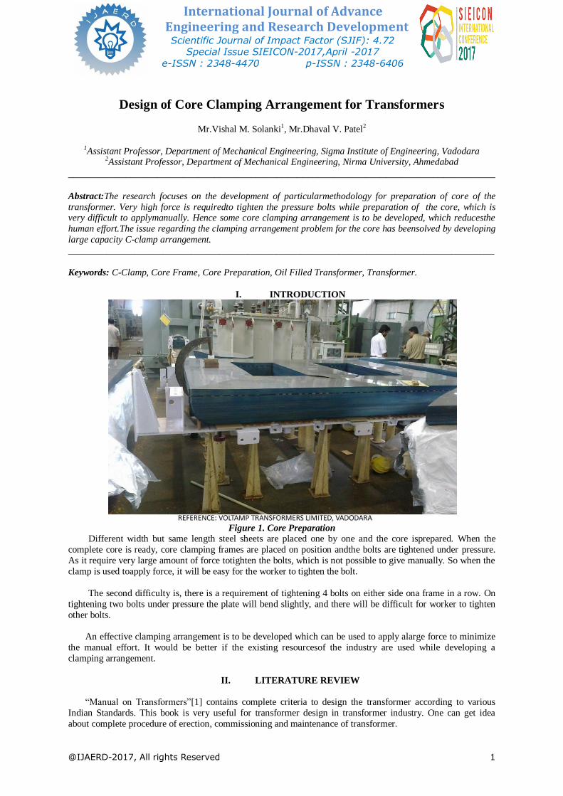
Figure 1. Core Preparation
Different width but same length steel sheets are placed one by one and the core isprepared. When the
complete core is ready, core clamping frames are placed on position andthe bolts are tightened under pressure.
As it require very large amount of force totighten the bolts, which is not possible to give manually. So when the
clamp is used toapply force, it will be easy for the worker to tighten the bolt.
The second difficulty is, there is a requirement of tightening 4 bolts on either side ona frame in a row. On
tightening two bolts under pressure the plate will bend slightly, and there will be difficult for worker to tighten
other bolts.
An effective clamping arrangement is to be developed which can be used to apply alarge force to minimize
the manual effort. It would be better if the existing resourcesof the industry are used while developing a
clamping arrangement.
II. LITERATURE REVIEW
“Manual on Transformers”[1] contains complete criteria to design the transformer according to various
Indian Standards. This book is very useful for transformer design in transformer industry. One can get idea
about complete procedure of erection, commissioning and maintenance of transformer.
International Journal of Advance Engineering and Research Development (IJAERD)
Special Issue SIEICON-2017, April -2017,e-ISSN: 2348 - 4470 , print-ISSN:2348-6406
@IJAERD-2017, All rights Reserved 2
Similarly the “Transformers”[2] published by BHEL, Bhopal is another good book on transformer. In this
book one can get practical knowledge as well as theoretical knowledge about the transformer. In this book one
learns about principles of transformer, material used in transformer, electrical accessories used in transformer,
cooling arrangement, design procedure, testing, standards used, erection commissioning and maintenance of a
transformer.
In IS 2062,2006[3] complete specification of hot rolled low, medium and high tensile structural steel is
given. From this various mechanical and chemical properties of steel of various grades used in industry can be
referred.
“Engineering Mechanics of Solids”[4]is very advanced book of mechanics of solids. Author Popov has described all the aspects very good. One can get idea aboutsolution of various problem related to strength of
material.
Many formulas related to designing of various mechanical components used in anyindustry are given in
“Design data hand-book (for mechanical engineers)”[5].
“Westermann tables”[6], this handbook gives us formulas and basic concepts ofphysics and mechanical
engineering, which are very useful for basic understanding formechanical engineers.
Very good fundamental aspects of machine design are given in “Design of Machine Elements”[7] by author
V.B.Bhandari. One can get very useful information aboutvarious loadings arrangements and their calculations in this book.
“Standard terminology for power and distribution transformers”[8], standard terminology for power and
distribution transformers are given in this standard. This is known as IEEE C57.12.80 - 2010.
III. METHODOLOGY
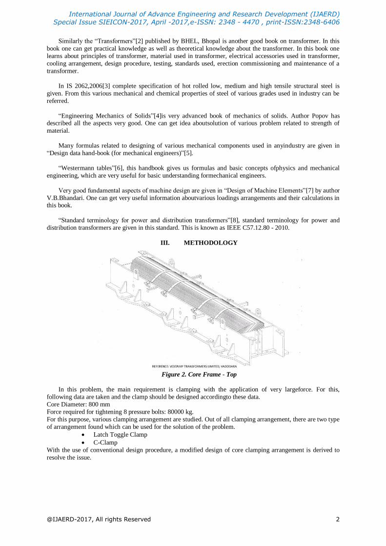
Figure 2. Core Frame - Top
In this problem, the main requirement is clamping with the application of very largeforce. For this,
following data are taken and the clamp should be designed accordingto these data.
Core Diameter: 800 mm
Force required for tightening 8 pressure bolts: 80000 kg.
For this purpose, various clamping arrangement are studied. Out of all clamping arrangement, there are two type
of arrangement found which can be used for the solution of the problem.
Latch Toggle Clamp
C-Clamp
With the use of conventional design procedure, a modified design of core clamping arrangement is derived to
resolve the issue.

International Journal of Advance Engineering and Research Development (IJAERD)
Special Issue SIEICON-2017, April -2017,e-ISSN: 2348 - 4470 , print-ISSN:2348-6406
@IJAERD-2017, All rights Reserved 3
IV. IMPLIMENTATION OF WORK
4.1. Latch Toggle Clamp[9]
Figure 3. Latch Toggle Clamp
This type of toggle clamp can also be used for this problem. But this type of clampis suitable only for
clamping with application of lesser force.As the diameter is large, the length of the latch should also be large,
which can bemanufactured, but the main requirement is the large clamping force, which cannot beapplied with
the help of this mechanism. So another arrangement should be developed.
4.2. C-Clamp
Figure 4. C-Clamp
As it is clearly seen in the first option in figure 4 that, the required force is to beapplied by rotating the lever
manually. But here the requirement of force is as high as20000 kg (for 2nos of pressure bolts). So a very large
human effort is required.
Thus, the second arrangement is used where the force is provided by pneumatic jackintegrated with C-
clamp arrangement. There is no manual effort needed and the available resources are to be used. This second
option is suitable according to requirement.
Here 20T pneumatic jack is used for applying the force.
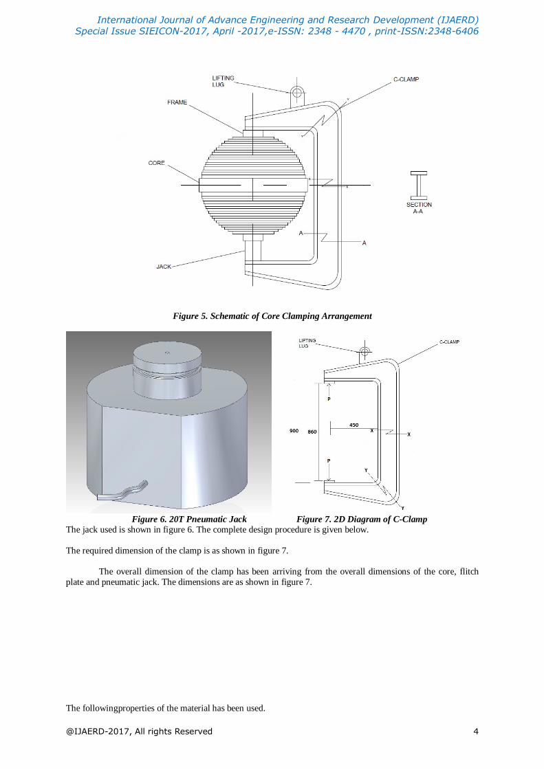
It is clearly seen from figure 5 that here a jack is used to apply force. This is apneumatic jack having 20
tonne maximum capacity. The jack is used because, 4 nos.of jack is available and they are to be used. So it is
required to design a C-Clamp usingthis jack for the load of 20 tonne which is required to clamp the core. In
figure 5, the cross-section of the core is shown. On top and bottom of the core, core frame ismounted. This core frame is bolted under very high force. This force is not possible toapply manually. So here pneumatic jack is
used. The jack is placed on bottom side ofthe core and then the force is applied. As the very high force is to be
applied, the sizeand shape of the clamp is designed accordingly.
International Journal of Advance Engineering and Research Development (IJAERD)
Special Issue SIEICON-2017, April -2017,e-ISSN: 2348 - 4470 , print-ISSN:2348-6406
@IJAERD-2017, All rights Reserved 4
Figure 5. Schematic of Core Clamping Arrangement
Figure 6. 20T Pneumatic Jack Figure 7. 2D Diagram of C-Clamp
The jack used is shown in figure 6. The complete design procedure is given below.
The required dimension of the clamp is as shown in figure 7.
The overall dimension of the clamp has been arriving from the overall dimensions of the core, flitch
plate and pneumatic jack. The dimensions are as shown in figure 7.
The followingproperties of the material has been used.
International Journal of Advance Engineering and Research Development (IJAERD)
Special Issue SIEICON-2017, April -2017,e-ISSN: 2348 - 4470 , print-ISSN:2348-6406
@IJAERD-2017, All rights Reserved 5
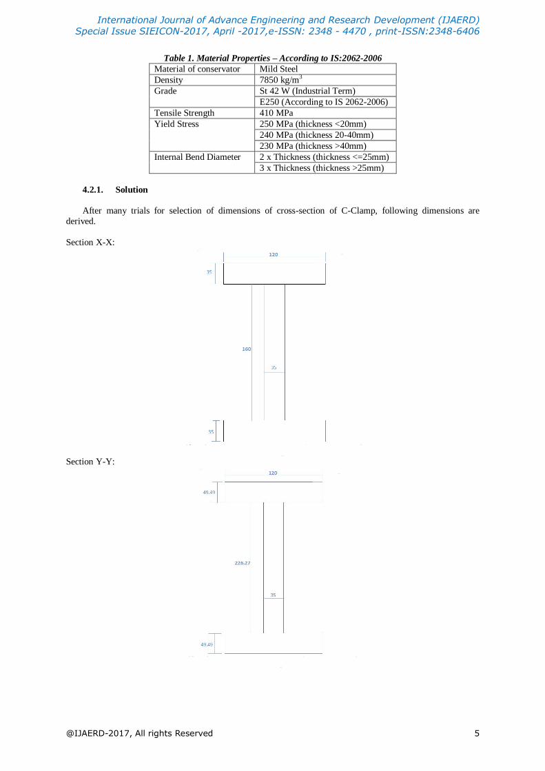
Table 1. Material Properties – According to IS:2062-2006
Material of conservator Mild Steel
Density 7850 kg/m3
Grade St 42 W (Industrial Term)
E250 (According to IS 2062-2006)
Tensile Strength 410 MPa
Yield Stress 250 MPa (thickness <20mm)
240 MPa (thickness 20-40mm)
230 MPa (thickness >40mm)
Internal Bend Diameter 2 x Thickness (thickness <=25mm)
3 x Thickness (thickness >25mm)
4.2.1. Solution
After many trials for selection of dimensions of cross-section of C-Clamp, following dimensions are
derived.
Section X-X:
Section Y-Y:
International Journal of Advance Engineering and Research Development (IJAERD)
Special Issue SIEICON-2017, April -2017,e-ISSN: 2348 - 4470 , print-ISSN:2348-6406
@IJAERD-2017, All rights Reserved 6
V. RESULTS AND DISCUSSION
Calculating stresses at various sections, following values are obtained which are within safe limit of
material properties.
Direct tensile stress at section X-X = 14:01MPa
Bending stress at section X-X = 135MPa(tensile)
Maximum tensile stress at section X-X = 149MPa
Direct tensile stress at section Y-Y = 7MPa
Bending stress at section Y-Y = 97.45MPa
Maximum tensile stress at inner corner of section Y-Y = 104.45MPa
Maximum compressive stress at outer corner of section Y-Y = 90.45MPa
Maximum Shear Stress at section Y-Y = 52.69MPa
Factor of Safety = 1.7
Stress in weld of lifting lug = 2.18MPa
VI. CONCLUSION
Latch toggle clamp mechanism cannot be used here because it cannot be used wherethe requirement of
force is very high. So design of C-clamp is necessary.
A C-clamp of capacity of 20 tonne is designed. Size of a clamp is derived byanalytical method. All the
calculations are made including welding stress calculationin the lifting lug, as the lifting lug may has to carry a
C-clamp of 190 kg.
REFERENCES
[1] “Manual on Transformers”; Central Board of Irrigation and Power, NewDelhi; March 2006.
[2] “Transformers”; Bharat Heavy Electricals Ltd, Bhopal; Tata McGrawHill Publications Ltd.; Second Edition
- 2002.
[3] Ammendment 1- IS 2062,2006; “Hot rolled low, medium and high tensile structural steel”.
[4] Egor P. Popov; “Engineering Mechanics of Solids”; Page no. 196-197; PHI Learning Pvt. Ltd; Second
Edition - 2011. [5] K.Mahadevan, K.Balaveerareddy; “Design data handbook (for mechanical engineers)”; Page no.169-171;
CBS Publishers & Distributors Pvt. Ltd.; Third Edition - 2011.
[6] “Westermann Tables”; Page no.30; New Age International Publications;Second Edition,2012.
[7] V.B.Bhandari; “Design of Machine Elements”; Tata McGraw Hill publications; Third Edition.
[8] IEEE C57.12.80 - 2010; “Standard terminology for power and distribution transformers”.
[9] Latch Toggle Clamp; http://toboc.com/flightindustrialcolimited/company-products.aspxas accessed on 9th
December 2012.