Design of compound die
27
Krishna Kumar Mishra Nikhil yadav Rohit Kumar Bind PROJECT SUPERVISOR: Dr. P.K Mishra
-
Upload
krishna-mishra -
Category
Design
-
view
329 -
download
6
Transcript of Design of compound die

Krishna Kumar Mishra
Nikhil yadav
Rohit Kumar Bind
PROJECT SUPERVISOR: Dr. P.K Mishra

STANDERD FLAT WASHER SIZE

CUTTING FORCEForce required to penetrate the stock material with the punch is the Cutting Force.
F = perimeter*thickness*Shear Strength = pi*D*t*S(for Circular Cross section)= 2(L+B)*t*S (for Rectangular Cross Section)
NOMINAL SIZE
INSIDEDIAMETER(mm)
OUT SIDE DIAMETER(mm)
THICKNESS(mm)
10 10.77 20 2.2

CUTTING FORCE
Alloy’s Shear Strength(Mpa)
PunchingForce(kN)
Blanking Force(kN)
A02010 269.1 20.02 37.178
A02040 175.0 13.02 24.178
A02950 143.65 10.68 19.846
A03280 111.8 8.31 15.446
A03550 134.55 10.01 18.589
Aluminium Alloys:

CUTTING FORCE
ALLOYS SHEAR STRENGTH (MPa)
PUNCHINGFORCE (kN)
BLANKING FORCE (kN)
COLD DRAWN 216.88 16.135 29.964
PHOSPHOROUS DEOXIDIZED
140.25 10.434 19.326
ZR COPPER 288.88 21.486 39.900
BRONZE 172.52 12.835 23.835
RED BRASS 181.03 13.468 25.011
NAVEL BRASS 283.65 21.103 39.189
NI AL BRONZE 453.48 33.738 62.652
Copper Alloys:

STAINLESS STEEL
SEAR STRENGTH(MPa) PUNCHING FORCE(kN) BLANKING FORCE(kN)
450 33.479 62.172

CLEARANCEC= .0032*t*sqrt(S) S : Shear strength of stock material t : Thickness of the strip

CLEARANCE FOR ALUMINIUM ALLOYS
Alloy Clearance
A0201 0.115
A0240 0.093
A02950 0.0843
A03280 0.0744
A03550 0.0816

CLEARANCE FOR COPPER ALLOYS
ALLOYS CLEAREANCE (mm)
COLD DRAWN 0.103
PHOSPHOROUS DEOXIDIZED 0.083
ZR COPPER 0.119
BRONZE 0.092
RED BRASS 0.094
NAVEL BRASS 0.118
NI AL BRONZE 0.150
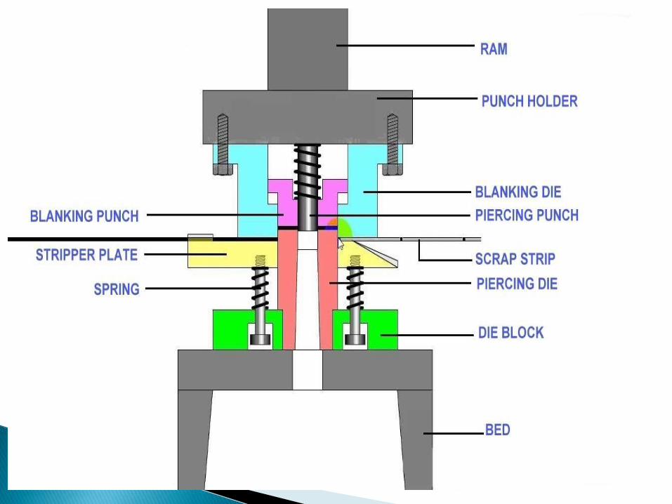

DESIGN OF PIERCING PUNCH:
WASHER MATERIAL : STAINLESS STEEL
ISO7089 ; Nominal size - 10
Internal Diameter (mm)
Outer Diameter (mm) Thickness (mm)
10.77 20 2.2
Size of Punch = Max. Diameter = 10.77 mmSize of Die = Max. Diameter + 2c = 11.0686 mm

Punch length :Maximum Permissible free length of circular Punches to be safe against Buckling.
Maximum Length of Punch :L = (pi*d/4)*((E*d)/(S*t))^1/2 ;
Modulus of elasticty = 207 GPa
PUNCH LENGTH =197.178 mm

DESIGN OF PUNCH FOR ALUMINIUM ALLOYS
Alloy Size of Punch(mm) Size of Die(mm)
A02010 10.77 11
A02040 10.77 10.956
A02950 10.77 10.938
A03280 10.77 10.918
A03550 10.77 10.933

DESIGN OF PUNCH FOR COPPER ALLOY
ALLOYS SIZE OF PUNCH (mm) SIZE OF DIE (mm)
COLD DRAWN 10.77 10.976
PHOSPHOROUS DEOXIDIZED
10.77 10.936
ZR COPPER 10.77 10.008
BRONZE 10.77 10.954
RED BRASS 10.77 10.958
NAVEL BRASS 10.77 11.006
NI BRONZE 10.77 11.070

DESIGN FOR BLANKING PUNCH:
Size of Punch = Max. Diameter – 2c = 19.7014 mmSize of Die = Max. Diameter = 20 mm
Aluminium Alloy Size of Punch (mm) Size of die (mm)
A02010 19.77 20
A02040 19.814 20
A02950 19.8314 20
A03280 19.8512 20
A03550 19.8368 20

COPPER ALLOYS SIZE OF PUNCH(mm) SIZE OF DIE (mm)
COLD DRAWN 19.790 20.000
PHOSPHOROUS DEOXIDIZED
19.830 20.000
ZR COPPER 19.762 20.000
BRONZE 19.816 20.000
RED BRASS 19.812 20.000
NAVAL BRASS 19.764 20.000
NI AL BRONZE 19.700 20.000

DIMENSIONS OF STRIPCalculated amount of distance has to be given between blanks and edge of strip to prevent scrap from twisting and wedging between punch and die.
Back Scrap (a)= t + .015d =2.5 mm ; t= thicknessScrap Bridge (b) = t = 2.2 mm d= diameter of blank
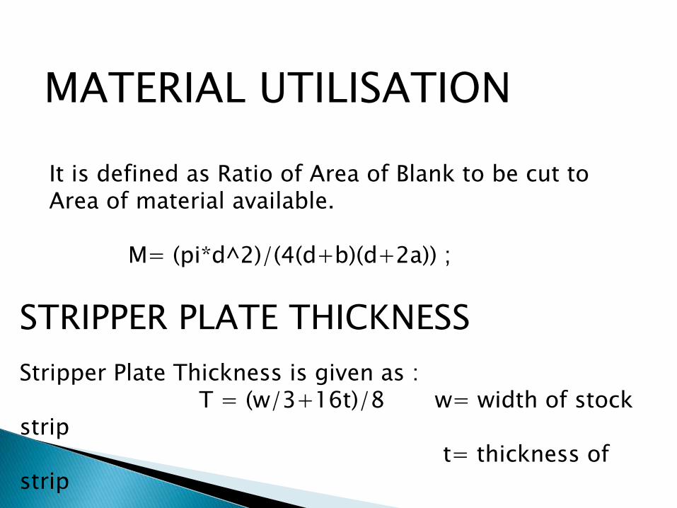
MATERIAL UTILISATION
It is defined as Ratio of Area of Blank to be cut to Area of material available.
M= (pi*d^2)/(4(d+b)(d+2a)) ;
STRIPPER PLATE THICKNESS
Stripper Plate Thickness is given as :T = (w/3+16t)/8 w= width of stock
strip t= thickness of
strip

DIE BLOCK THICKNESS
The Die Block is the female half of two mated tools which carries the cutting edges.
Die thickness = 19 mm ,Blank Perimeter <=75Die thickness = 25 mm , Blank Perimeter = 70 mm to 250 mmDie Thickness = 30 mm , Blank Perimeter > 250 mm

ALUMINIUM ALLOYS
StripperForce(kN)
Material utilization
Blank perimeter(mm)
Die Block Thickness(mm)
A02010 3.7178 0.5657 62.8 19
A02040 2.4178 0.5657 62.8 19
A02950 1.984 0.5657 62.8 19
A03280 1.544 0.5657 62.8 19
A03550 1.858 0.5657 62.8 19
STRIPPER FORCE ;MATERIAL UTILIZATION;BLANK PERIMETER;DIE BLOCK THICKNESS:

COPPER ALLOYS Stripper Force (kN)
Materialutilization
Die block Perimeter(mm)
Die blockThickness(mm)
COLD DRAWN 2.996 0.5657 62.800 19
PHOSPHOROUS DEOXIDIZED
1.937 0.5657 62.800 19
ZR COPPER 3.990 0.5657 62.800 19
BRONZE 2.380 0.5657 62.800 19
RED BRASS 2.501 0.5657 62.800 19
NAVEL BRASS 3.918 0.5657 62.800 19
NI AL BRONZE 6.265 0.5657 62.800 19
STRIPPER FORCE ;MATERIAL UTILIZATION;BLANK PERIMETER;DIE BLOCK THICKNESS:

DESIGN OF SPRING
MATERIAL OF SPRING:STAINLESS STEEL
Let no. of springs be 4Maximum force spring can exert (Fs)=(Stripper Force)/(No.of Springs);Wahl facto(K)=1.4;Diameter of wire(d)=K*sqrt((8*Fs*D)/(S*d));Spring Index=D/d=4;Movement of stripper = (t+2) mm;Spring Deflection=(3*movement of stripper);Compressed Length(l)=(1.1*n*d)+D;Free Length(L)=compressed Length +Spring Deflection;

Stripper Force = 6.2172 kNMaximum force spring can exert(Fs)= 2.3314 kNMovement of Stripper = 4.2 mmSpring Deflection = 12.6 mmDiameter of wire = 18 mmDiameter of coil (D) = 72.08 mmCompressed Length(l) = 31.5 cmFree Length = 32.76 cm

Design of Components
Washer Dimension:Internal Diameter : 10.77 mmOutside Diameter : 20 mmThickness : 2.2 mm
PunchingPunch Diameter : 10.77 mmDie Diameter : 11.0686 mm
MATERIAL : AUSTENITIC STAINLESS STEEL

BLANKING
BLANKING PUNCH DIAMETER : 19.7014mmBLANKING DIE DIAMETER : 20.0000mm
SPRING DESIGN
Let No. of spring. = 4Diameter of wire (d) =18 mmDiameter of coil = 72.08mm

STRIPPER PLATE
Stripper plate thickness = 5.233mm
CUTTING FORCE = pi*D*t*S
Blanking force = 62.172mmPunching force = 33.479mm

Thank You