
A PROJECT REPORT IS ON CLOSED LOOP SERVO HYDRAULIC ACTUATION SYSTEM
International Journal of Computational Engineering Research||Vol, 04||Issue, 1||
||Issn 2250-3005 || ||January||2014|| Page 49
Design of Closed Loop Electro Mechanical Actuation System
Poondla.Chiranjeevi1, J.Venkatesu Naik
2
1PG Student, Department of Mechanical Engineering, Chadalawada Ramanamma Engineering College.
2Assistant Professor, Department of Mechanical Engineering, Chadalawada Ramanamma Engineering College, Tirupati, AP, India.
I. INTRODUCTION This document covers the description, design, inputs and specifications of the Actuation System for aerodynamic control of an Aero-vehicle. The document also describes the actuator specifications, mechanical
components, BLDC motor, position sensor and the control system including simulation.
1.1. Actuator
An actuator is a mechanism that converts energy into motion. It can also be used to apply a force. An
actuator typically is a mechanical device that takes energy, usually created by air, electricity, or liquid, and
converts that into some kind of motion. That motion can be anything from blocking to clamping to ejecting.
Actuators are typically used in manufacturing or industrial applications and may be used in things like motors,
pumps, switches, and valves. The most common type of actuator is powered by air — the pneumatic cylinder,
also known as the aircylinder. Air cylinders are air-tight cylinders, typically made from metal, that use the
energy of compressed air to move a piston. Air cylinders are most commonly used in manufacturing and
assembly processes. Grippers, which are used in robotics, use actuators driven by compressed air to work much like human fingers.Actuators can also be powered by electricity or hydraulics. Much like there are air cylinders,
there are also electric cylinders and hydraulic cylinders where the cylinder converts electricity or hydraulics into
motion. Hydraulic cylinders are often used in certain types of vehicles.
Many actuators have more than one type of power source. Solenoid valves, for example, can be
powered by air and electricity. Electricity powers the solenoid, and the solenoid, powered by air actuates the
valve. Alternatively, the solenoid can be powered by hydraulics and electricity.Actuators can create a linear
motion, rotary motion, or oscillatory motion. That is, they can create motion in one direction, in a circular
motion, or in opposite directions at regular intervals. Hydraulic and air cylinders can be classified as single
acting, meaning that the energy source causes movement in one direction and a spring is used for the other
direction. Alternatively, these cylinders can be double acting cylinders, meaning the energy is used in two directions. While actuators are typically discussed in terms of mechanical implements, muscles are sometimes
given as an example of an actuator. Energy (e.g., created by eating carbohydrates) is converted by the muscle
(i.e., the actuator) into motion (e.g., kicking a ball).
ABSTRACT: An Actuator is basically a position servo control system used in industries and vehicles.
A rotary electro mechanical actuation system is an angular positioning system used in aerospace
applications such as control of rudder and ailerons of aero planes and control of control surfaces, jet
vanes, etc. This position loop system is to steer the vehicle to move in required direction.
A servo controller is a driver to accurately control the position of the actuation system by getting the
command signals from the on-board computer of the vehicle. It involves a class of DSP controller optimized for digital motor motion control and power conversion applications.
In this thesis, Closed loop Rotary Electro Mechanical Actuating system is designed for the derived
specifications by using the CAD software UNIGRAPHICS, and simulated the design with the help of
FEA software ANSYS and MATLAB.
KEYWORDS: Actuator, ANSYS, CAD, DSP controller, UNIGRAPHICS.
Design Of Closed Loop Electro Mechanical…
||Issn 2250-3005 || ||January||2014|| Page 50
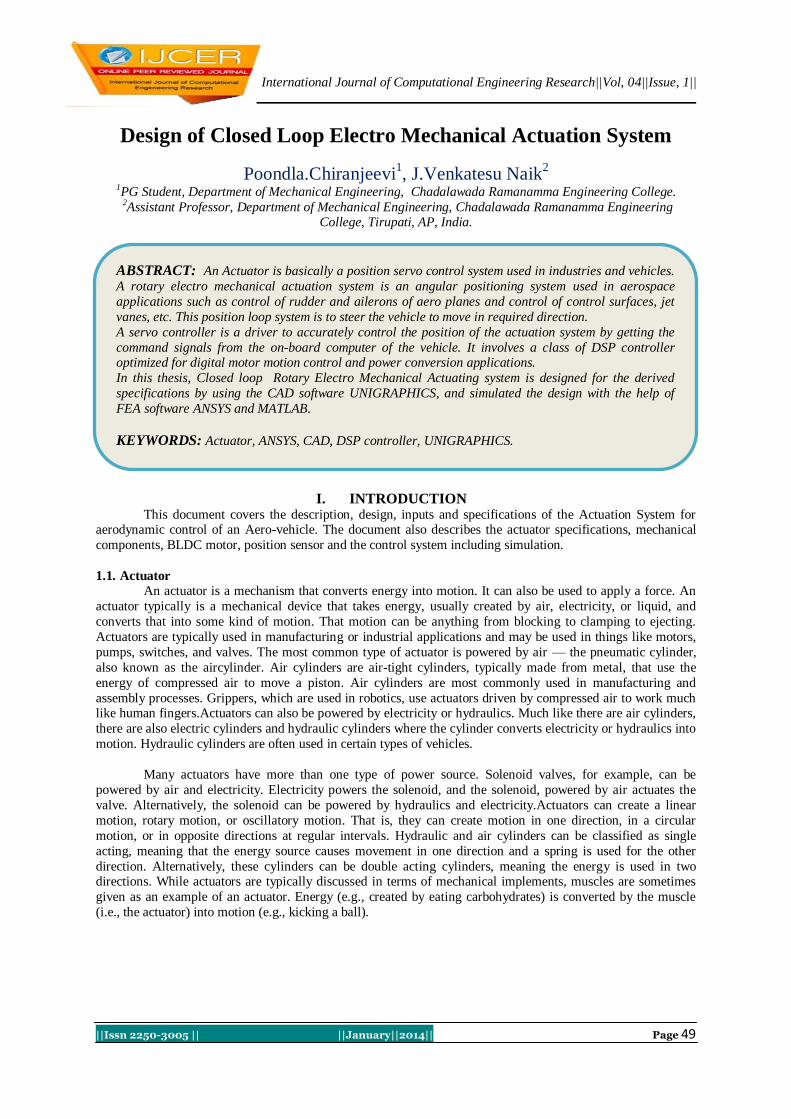
Fig 1.Mechanism of Actuator Fig 2. Block diagram of actuator
II. DESCRIPTION AND CONFIGURATION OF ACTUATOR The actuator configuration is as follows….
Prime mover is a 3 phase BLDC motor.
Transmission by Planetary gear train.
Position feedback element is Rotary potentiometer.
Servo control by DSP controller.
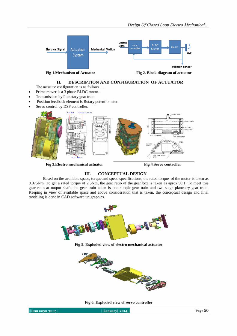
Fig 3.Electro mechanical actuator Fig 4.Servo controller
III. CONCEPTUAL DESIGN Based on the available space, torque and speed specifications, the rated torque of the motor is taken as
0.075Nm. To get a rated torque of 2.5Nm, the gear ratio of the gear box is taken as aprox.50:1. To meet this
gear ratio at output shaft, the gear train taken is one simple gear train and two stage planetary gear train.
Keeping in view of available space and above consideration that is taken, the conceptual design and final
modeling is done in CAD software unigraphics.
Fig 5. Exploded view of electro mechanical actuator
Fig 6. Exploded view of servo controller
Design Of Closed Loop Electro Mechanical…
||Issn 2250-3005 || ||January||2014|| Page 51
IV. DESIGN OF ACTUATOR 4.1 Defining motor inputs for motor selection
To achieve the given specifications, the gear ratio is taken as 50 and after conceptual design by taking
module of 0.6, the final gear ratio achieved is 49.25:1
4.2 Gear box efficiency
S
p
u
r
G
ear Efficiency = 96.13 %
Planetary Gear Efficiency = 79.28%
Total Gear Box Efficiency = 76.21%
Stall torque of motor should be considered greater than 0.1183 N-m for 49.25 gear
Rated torque of motor should be considered greater than 0.0679 N-m for 49.25
4.3 Gear box design From outline specifications and space availability the gear box sizes finalized as Ø40 x 41 and selected
Gear Ratio as 49.25
The total gear ratio divided to spur gear reduction and planetary gear reduction.
Spur Gear Reduction = 3.8
Planetary Gear Reduction for two stages = 12.96
Each Stage Planetary Reduction = 3.6
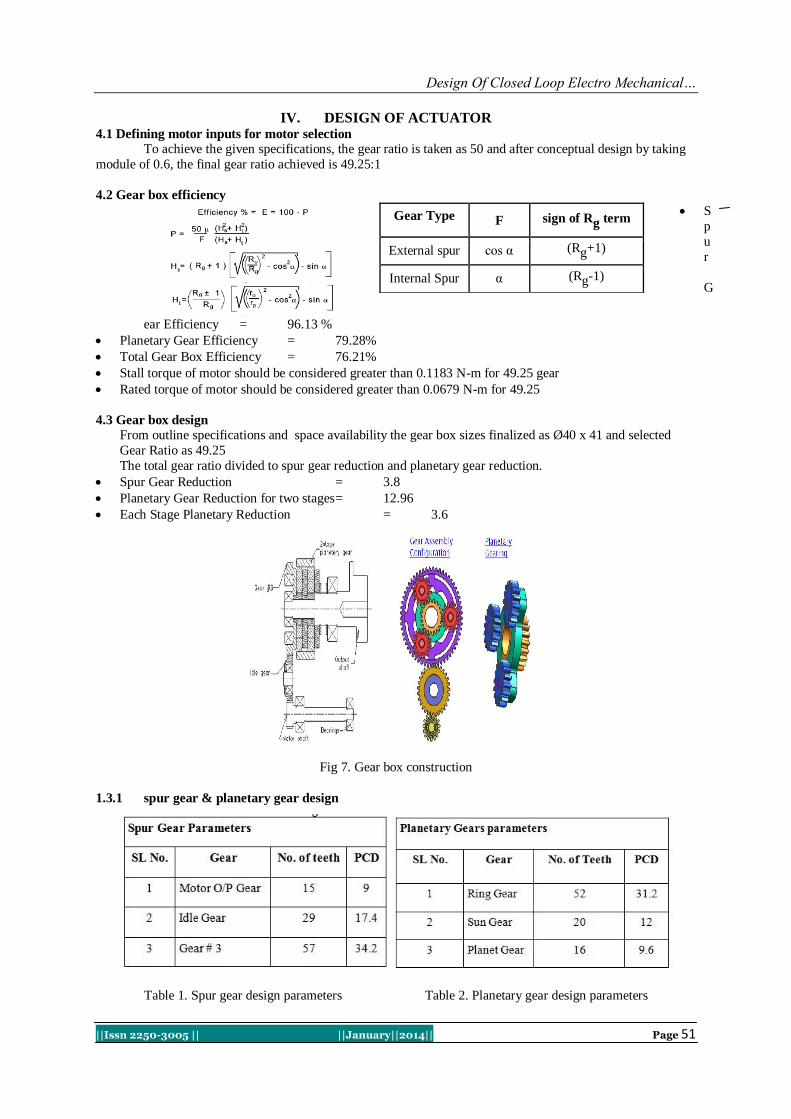
Fig 7. Gear box construction
1.3.1 spur gear & planetary gear design
Table 1. Spur gear design parameters Table 2. Planetary gear design parameters
Gear Type F sign of Rg term
External spur cos α (Rg+1)
Internal Spur α (Rg-1)

Design Of Closed Loop Electro Mechanical…
||Issn 2250-3005 || ||January||2014|| Page 52
If consider 3Nos of Planet Gears of 2.6 (Excluding chamfers) mm face width than Factor of safety = 5
If consider 5Nos of Planet Gears of 4 mm (Excluding chamfers) face width than Factor of safety =
2.2 (Since we are calculated for Peak Torque)
V. STRUCTURAL ANALYSIS OF OUTPUT SHAFT Type of element: tetrahedron in ansys
Stress developed in the shaft due twisting and bending force material : SS 420
No. of nodes: 262440
No. of elements: 181487 Fig 8. Meshing of output shaft
5.1 Supports & Load Conditions:
Cylindrical support at bearing surfaces Fixed support at key way Moment at output of shaft (4500 N
mm)
Fig 9. Supports and Loads on output shaft
5.2 Solution:
Equivalent stress (Von Mises)
Fig 10. Equivalent stresses on output shaft

Design Of Closed Loop Electro Mechanical…
||Issn 2250-3005 || ||January||2014|| Page 53
Part Allowable stress(N/mm2) Results in ANSYS(N/mm2),MAX
Output shaft 448 315.37
Table-3
Structural analysis of housing in ansys
Stress developed in the housing due to twisting(motor and bending load:
Material : 1. Output shaft= SS420
o 2. Housing= Al(HE 15)
Type of element : Tetrahedron
No. of nodes: 226198
No. of Elements : 146290
Fig 11. Meshing of stator housing and output shaft Fig 12. Boundary conditions on housing
6.1 Boundary Conditions
2 bearings are fixed to housing
Output shaft is fixed to 2 bearings
Bending load applied at shaft is 360N
Moment applied at stator position is 4.5Nm
6.2 Solution
Design Of Closed Loop Electro Mechanical…
||Issn 2250-3005 || ||January||2014|| Page 54
Fig 13. Equivalent stress on housing
Part Allowable stress(N/mm2) Results in ANSYS(N/mm2),MAX
Output shaft 448 75.283
Housing 37.5 18.138
Table- 4
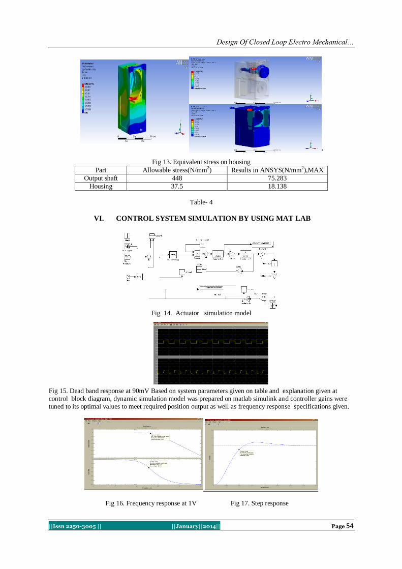
VI. CONTROL SYSTEM SIMULATION BY USING MAT LAB
Fig 14. Actuator simulation model
Fig 15. Dead band response at 90mV Based on system parameters given on table and explanation given at
control block diagram, dynamic simulation model was prepared on matlab simulink and controller gains were
tuned to its optimal values to meet required position output as well as frequency response specifications given.
Fig 16. Frequency response at 1V Fig 17. Step response
Design Of Closed Loop Electro Mechanical…
||Issn 2250-3005 || ||January||2014|| Page 55
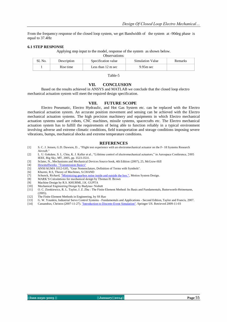
From the frequency response of the closed loop system, we get Bandwidth of the system at -90deg phase is
equal to 37.4Hz
6.1 STEP RESPONSE Applying step input to the model, response of the system as shown below.
Observations:
SL No. Description Specification value Simulation Value Remarks
1 Rise time Less than 12 m sec 9.95m sec
Table-5
VII. CONCLUSION Based on the results achieved in ANSYS and MATLAB we conclude that the closed loop electro
mechanical actuation system will meet the required design specification.
VIII. FUTURE SCOPE Electro Pneumatic, Electro Hydraulic, and Hot Gas System etc. can be replaced with the Electro
mechanical actuation system. An accurate position movement and sensing can be achieved with the Electro
mechanical actuation systems. The high precision machinery and equipments in which Electro mechanical
actuation systems used are robots, CNC machines, missile systems, spacecrafts etc. The Electro mechanical
actuation system has to fulfill the requirements of being able to function reliably in a typical environment
involving adverse and extreme climatic conditions, field transportation and storage conditions imposing severe
vibrations, bumps, mechanical shocks and extreme temperature conditions.
REFERENCES [1] S. C. J. Jensen, G.D. Dawson, D. , "Flight test experience with an electromechanical actuator on the F- 18 Systems Research
Aircraft."
[2] L. U. Gokdere, S. L. Chiu, K. J. Keller et al., “Lifetime control of electromechanical actuators,” in Aerospace Conference, 2005
IEEE, Big Sky, MT, 2005, pp. 3523-3531.
[3] Sclater, N., Mechanisms and Mechanical Devices Source book, 4th Edition (2007), 25, McGraw-Hill
[4] Howstuffworks "Transmission Basics"
[5] ANSI/AGMA 1012-G05, "Gear Nomenclature, Definition of Terms with Symbols".
[6] Khurmi, R.S, Theory of Machines, S.CHAND
[7] Schunck, Richard, "Minimizing gearbox noise inside and outside the box.", Motion System Design.
[8] MARK’S Calculations for mechanical design by Thomas H. Brown
[9] Machine Design by R.S. KHURMI, J.K. GUPTA
[10] Mechanical Engineering Design by Budynas−Nisbett
[11] O. C. Zienkiewicz, R. L. Taylor, J. Z. Zhu : The Finite Element Method: Its Basis and Fundamentals, Butterworth-Heinemann,
(2005).
[12] The Finite Element Methods in Engineering, by SS Rao
[13] G. W. Younkin, Industrial Servo Control Systems - Fundamentals and Applications - Second Edition, Taylor and Francis, 2007.
[14] Cassandras, Christos (2007-11-27). "Introduction to Discrete-Event Simulation". Springer US. Retrieved 2009-11-03


