Design of Clean Agent Fire Extinguishing System as Per Nfpa 2001 Standards With Respect to Fire...
31
PROCEEDINGS OF FIRE SCIENCE AND TECHNOLOGY- RESEARCH & ITS IMPLEMENTATIONS- NOV. 3-4, 2011 FIRST 2011 DESIGN OF CLEAN AGENT FIRE EXTINGUISHING SYSTEM AS PER NFPA 2001 STANDARDS WITH RESPECT TO FIRE HAZARD SCENARIOS IN INDIA R.S. Chimote*, Prof. Shashi**, Prof. Surendra Kumar** and Reshu Sharma* *Fire research laboratory, CSIR-Central Building Research Institute, Roorkee **Department of Chemical Engineering, Indian Institute of Technology Roorkee ABSTRACT This paper highlights the phase-out of the halogenated fire extinguishing agents: 1301, 1211 etc due to ozone depletion potential problems under Montreal protocol and further, briefly describes the clean agent fire extinguishing system design considerations with two Case-illustrations: Case 1 and Case 2, that are required to be designed to extinguish fires either by flame extinguishment or by inerting in accordance with the changing characteristics of fire hazard scenarios in building and industrial occupancies. What is very important for reduction of the flammable concentration in an atmosphere is the inerting which is required to be done below one-half of its lower flammable limit. Flame extinguishment shall be designed to cease combustion of a combustible solid or a flammable or combustible liquid. The characteristics of fire hazard scenarios with respect to anticipated fires have been continuously changing in India due to emerging trends in the up gradation/ modern furnishing and interior design considerations/ requirements in almost all the urban and semi- urban occupancies. Rural India has been picking up at little slower pace. The clean agent system design considerations must be planned and designed for urban and semi-urban occupancies in India such that the fire extinguishant-containers should not be in the hazardous area, and it shall suitably be in a protected location as close as possible to the hazard. Piping and fittings must be of a pressure rating commensurate with expected Fire Research Laboratory, CSIR-Central Building Research Institute, Roorkee (UK) INDIA 191
-
Upload
khoirul-walad -
Category
Documents
-
view
68 -
download
2
description
Design of Clean Agent Fire Extinguishing System as Per Nfpa 2001 Standards With Respect to Fire Hazard Scenarios
Transcript of Design of Clean Agent Fire Extinguishing System as Per Nfpa 2001 Standards With Respect to Fire...
PROCEEDINGS OF FIRE SCIENCE AND TECHNOLOGY- RESEARCH & ITS
IMPLEMENTATIONS- NOV. 3-4, 2011
FIRST 2011
DESIGN OF CLEAN AGENT FIRE EXTINGUISHING SYSTEM AS PER NFPA 2001 STANDARDS WITH RESPECT TO FIRE HAZARD SCENARIOS IN INDIA
R.S. Chimote*, Prof. Shashi**, Prof. Surendra Kumar** and Reshu Sharma**Fire research laboratory, CSIR-Central Building Research Institute, Roorkee **Department of Chemical Engineering, Indian Institute of Technology Roorkee
ABSTRACT
This paper highlights the phase-out of the halogenated fire extinguishing agents: 1301, 1211 etc due to ozone depletion potential problems under Montreal protocol and further, briefly describes the clean agent fire extinguishing system design considerations with two Case-illustrations: Case 1 and Case 2, that are required to be designed to extinguish fires either by flame extinguishment or by inerting in accordance with the changing characteristics of fire hazard scenarios in building and industrial occupancies. What is very important for reduction of the flammable concentration in an atmosphere is the inerting which is required to be done below one-half of its lower flammable limit. Flame extinguishment shall be designed to cease combustion of a combustible solid or a flammable or combustible liquid. The characteristics of fire hazard scenarios with respect to anticipated fires have been continuously changing in India due to emerging trends in the up gradation/ modern furnishing and interior design considerations/ requirements in almost all the urban and semi-urban occupancies. Rural India has been picking up at little slower pace. The clean agent system design considerations must be planned and designed for urban and semi-urban occupancies in India such that the fire extinguishant-containers should not be in the hazardous area, and it shall suitably be in a protected location as close as possible to the hazard. Piping and fittings must be of a pressure rating commensurate with expected system pressures, and must be corrosion-resistant. Piping and fittings must be metallic, and the fittings can not be of cast iron and it may be of welded, brazed, or malleable iron. Fire suppression and detection shall be selected /designed to be intelligent for the anticipated class of fires and emerging fire load density pattern/layout with appropriately designed discharge flow rate, particle/droplet size distribution with respect to fire extinguishing efficiency parameters. An existing detection system may possibly be reused
Fire Research Laboratory, CSIR-Central Building Research Institute, Roorkee (UK) INDIA 191
R.S. Chimote, Prof. Shashi, Prof. Surendra Kumar and Reshu Sharma
when designing a clean agent system, provided that the characteristics of the anticipated fire have not been changed.
INTRODUCTION
The results of a study of the effect of chlorofluorocarbons (CFCs) on the ozone layer won the Nobel Prize for two chemists (1-19, 20) at the University of California Irvine, Frank Sherwood Rowland and Mario Mocina which resulted in a landmark international agreement, the Montreal Protocol, signed by the United States and 24 other countries in 1987, with significant amendments in 1990 and 1992.
Kofi Annan, former Secretary General of the United Nations, said “perhaps the single most successful international agreement to date was the Montreal Protocol of 1987.” The agreement was intended to sharply restrict the production of chemicals that had been identified as contributing to depletion of the stratospheric ozone layer. The ozone layer is a protective layer of our stratosphere that helps to filter the ultraviolet rays of the sun before they reach Earth. In the absence of the ozone layer, the incidence of skin cancer and melanoma increase. An ozone molecule consists of three oxygen atoms (O3). Freon, released from air conditioners, and halogenated extinguishing agents rise to the stratosphere. Bromine and chlorine molecules from these agents break up the O3 molecules and attach themselves to one of the free oxygen molecules. These gases, therefore, were included in the list of ozone depleting agents.
In advance of the Montreal Protocol, the Vienna Convention for the Protection of the Ozone Layer provided the framework for negotiations in 1985. Immediately subsequent to the initial signing of the Montreal Protocol, evidence continued to mount that the ozone layer was continuing to shrink at a frightening rate. Numerous additional countries signed the Montreal Protocol, and the target date for ceasing production of halogenated hydrocarbons was advanced to January 1994. At present, 191 nations have signed the Montreal Protocol, making it one of the planet’s most successful international agreements.
The cessation of halon production rapidly rendered existing halon systems which are to be gradually phased out of the fire protection industry, has placed owners of halon systems and the companies that insure the hazards protected by halon systems, in an extremely uncomfortable position. Although the Montreal Protocol did not call for removing all existing halon systems, it prohibited the manufacture of new halon- making it impractical to legally purchase new halons. Owners and insurers of halon systems were faced with the prospect of a total loss of fire
Fire Research Laboratory, CSIR-Central Building Research Institute, Roorkee (UK) INDIA 192

Design of clean agent fire extinguishing system as per NFPA 2001 standards with respect to fire hazard scenarios in India
protection pursuant to an accidental or purposeful halon system discharge.
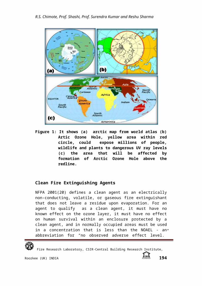
Figure 1 shows (1-19, 20) (a) Arctic map from world atlas (b) Artic Ozone Hole, yellow area within red circle, could expose millions of people, wildlife and plants to dangerous UV ray levels; and (c) the area that will be affected by formation of Arctic Ozone Hole above the redline. To protect against this eventuality, many system owners opted to replace their halon systems with either a substitute gaseous system replacement or a water-based system replacement. Although introductory background of halon’s replacements is covered in this paper, the primary focus is on clean agents and halon alternative fire extinguishing agents.
Figure 1: It shows (a) arctic map from world atlas (b) Artic Ozone Hole, yellow area within red circle, could expose millions of people, wildlife and plants to dangerous UV ray levels (c) the area that will be affected by formation of Arctic Ozone Hole above the redline.
Clean Fire Extinguishing Agents
NFPA 2001(20) defines a clean agent as an electrically non-conducting, volatile, or gaseous fire extinguishant that does not
Fire Research Laboratory, CSIR-Central Building Research Institute, Roorkee (UK) INDIA 193
R.S. Chimote, Prof. Shashi, Prof. Surendra Kumar and Reshu Sharma
leave a residue upon evaporation. For an agent to qualify as a clean agent, it must have no known effect on the ozone layer, it must have no effect on human survival within an enclosure protected by a clean agent, and in normally occupied areas must be used in a concentration that is less than the NOAEL - an abbreviation for “no observed adverse effect level.” NOAEL is a measure of clean agent toxicity to humans, under test conditions.
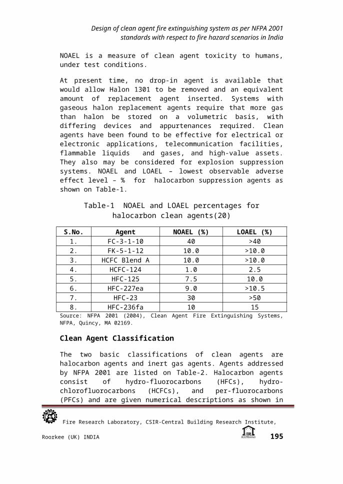
At present time, no drop-in agent is available that would allow Halon 1301 to be removed and an equivalent amount of replacement agent inserted. Systems with gaseous halon replacement agents require that more gas than halon be stored on a volumetric basis, with differing devices and appurtenances required. Clean agents have been found to be effective for electrical or electronic applications, telecommunication facilities, flammable liquids and gases, and high-value assets. They also may be considered for explosion suppression systems. NOAEL and LOAEL – lowest observable adverse effect level – % for halocarbon suppression agents as shown on Table-1.
Table-1 NOAEL and LOAEL percentages for halocarbon clean agents(20)
S.No. Agent NOAEL (%) LOAEL (%)1. FC-3-1-10 40 >402. FK-5-1-12 10.0 >10.03. HCFC Blend A 10.0 >10.04. HCFC-124 1.0 2.55. HFC-125 7.5 10.06. HFC-227ea 9.0 >10.57. HFC-23 30 >508. HFC-236fa 10 15
Source: NFPA 2001 (2004), Clean Agent Fire Extinguishing Systems, NFPA, Quincy, MA 02169.
Clean Agent Classification
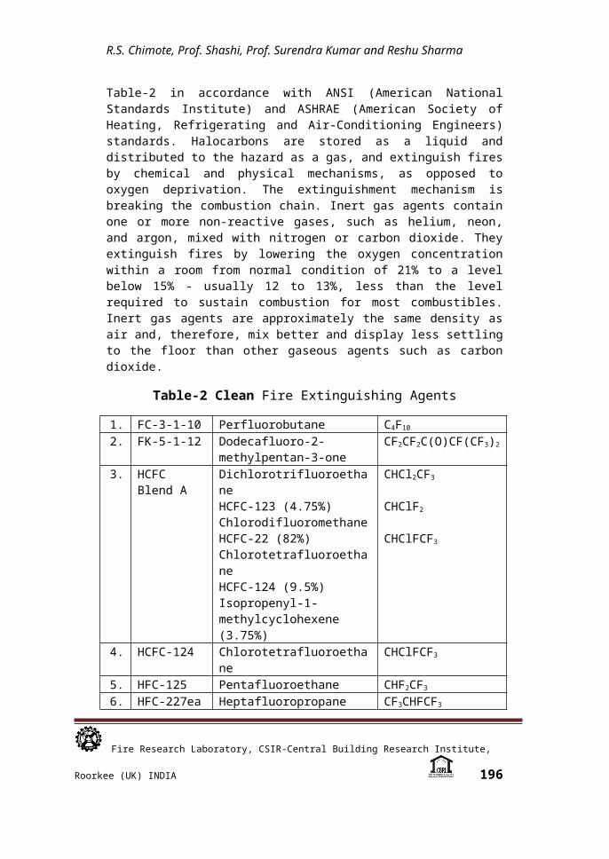
The two basic classifications of clean agents are halocarbon agents and inert gas agents. Agents addressed by NFPA 2001 are listed on Table-2. Halocarbon agents consist of hydro-fluorocarbons (HFCs), hydro-chlorofluorocarbons (HCFCs), and per-fluorocarbons (PFCs) and are given numerical descriptions as shown in Table-2 in accordance with ANSI (American National Standards Institute) and ASHRAE (American Society of Heating, Refrigerating and Air-Conditioning Engineers) standards. Halocarbons are stored as a liquid and distributed to the hazard as a gas, and extinguish fires by chemical and physical mechanisms, as opposed to oxygen deprivation. The extinguishment mechanism is breaking the combustion chain. Inert gas agents
Fire Research Laboratory, CSIR-Central Building Research Institute, Roorkee (UK) INDIA 194
Design of clean agent fire extinguishing system as per NFPA 2001 standards with respect to fire hazard scenarios in India
contain one or more non-reactive gases, such as helium, neon, and argon, mixed with nitrogen or carbon dioxide. They extinguish fires by lowering the oxygen concentration within a room from normal condition of 21% to a level below 15% - usually 12 to 13%, less than the level required to sustain combustion for most combustibles. Inert gas agents are approximately the same density as air and, therefore, mix better and display less settling to the floor than other gaseous agents such as carbon dioxide.
Table-2 Clean Fire Extinguishing Agents
1. FC-3-1-10 Perfluorobutane C4F10
2. FK-5-1-12 Dodecafluoro-2-methylpentan-3-one
CF2CF2C(O)CF(CF3)2
3. HCFCBlend A
DichlorotrifluoroethaneHCFC-123 (4.75%)ChlorodifluoromethaneHCFC-22 (82%)ChlorotetrafluoroethaneHCFC-124 (9.5%)Isopropenyl-1-methylcyclohexene (3.75%)
CHCl2CF3
CHClF2
CHClFCF3
4. HCFC-124 Chlorotetrafluoroethane CHClFCF3
5. HFC-125 Pentafluoroethane CHF2CF3
6. HFC-227ea Heptafluoropropane CF3CHFCF3
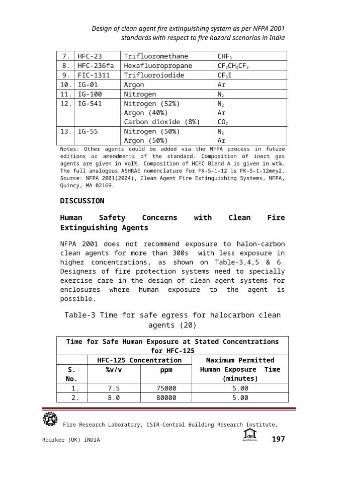
7. HFC-23 Trifluoromethane CHF3
8. HFC-236fa Hexafluoropropane CF3CH2CF3
9. FIC-1311 Trifluoroiodide CF3I10. IG-01 Argon Ar11. IG-100 Nitrogen N2
12. IG-541 Nitrogen (52%)Argon (40%)Carbon dioxide (8%)
N2
ArCO2
13. IG-55 Nitrogen (50%)Argon (50%)
N2
ArNotes: Other agents could be added via the NFPA process in future editions or amendments of the standard. Composition of inert gas agents are given in Vol%. Composition of HCFC Blend A is given in wt%. The full analogous ASHRAE nomenclature for FK-5-1-12 is FK-5-1-12mmy2. Source: NFPA 2001(2004), Clean Agent Fire Extinguishing Systems, NFPA, Quincy, MA 02169.
DISCUSSION
Human Safety Concerns with Clean Fire Extinguishing Agents
NFPA 2001 does not recommend exposure to halon-carbon clean agents for more than 300s with less exposure in higher
Fire Research Laboratory, CSIR-Central Building Research Institute, Roorkee (UK) INDIA 195
R.S. Chimote, Prof. Shashi, Prof. Surendra Kumar and Reshu Sharma
concentrations, as shown on Table-3,4,5 & 6. Designers of fire protection systems need to specially exercise care in the design of clean agent systems for enclosures where human exposure to the agent is possible.
Table-3 Time for safe egress for halocarbon clean agents (20)
Time for Safe Human Exposure at Stated Concentrations for HFC-125
HFC-125 Concentration Maximum Permitted Human Exposure Time
(minutes)S. No. %v/v ppm
1. 7.5 75000 5.002. 8.0 80000 5.003. 8.5 85000 5.004. 9.0 90000 5.005. 9.5 95000 5.006. 10.0 100000 5.007. 10.5 105000 5.008. 11.0 110000 5.009. 11.5 115000 5.00
10. 12.0 120000 1.6711. 12.5 125000 0.59
12. 13.0 130000 0.54 13. 13.5 135000 0.49
Notes: Data derived from the EPA-approved and peer reviewed physiologically based pharmacokinetic (PBPK) model or its equivalent. Based on LOAEL of 10.0 % in dogs.
Table-4 Time for Safe Human Exposure at Stated Concentrations for HFC-236fa (20)
Time for Safe Human Exposure at Stated Concentrations for HFC-236fa
HFC-236fa Concentration Maximum Permitted Human Exposure Time
(min)
S.No. %v/v ppm
1. 10.0 100000 5.002. 10.5 105000 5.003. 11.0 110000 5.004. 11.5 115000 5.005. 12.0 120000 5.006. 12.5 125000 5.007. 13.0 130000 1.658. 13.5 135000 0.929. 14.0 140000 0.79
10. 14.5 145000 0.64
Fire Research Laboratory, CSIR-Central Building Research Institute, Roorkee (UK) INDIA 196
Design of clean agent fire extinguishing system as per NFPA 2001 standards with respect to fire hazard scenarios in India
11. 15.0 150000 0.49Notes: Data derived from EPA-approved/peer-reviewed PBPK model on LOAEL of 15% in dogs.
Table-5 Time for Safe Human Exposure at Concentrations for HFC-227ea (20)
Time for Safe Human Exposure at Stated Concentrations for HFC-227ea
HFC-227eaConcentration
Maximum Permitted
Human Exposure Time
(minutes)
S.No. %v/v ppm
1. 9.0 90000 5.002. 9.5 95000 5.003. 10.0 100000 5.004. 10.5 105000 5.005. 11.0 110000 1.136. 11.5 115000 0.607. 12.0 120000 0.49
Notes: Data derived from EPA-approved/peer-reviewed PBPK model on LOAEL of 10.5% in dogs.
Table-6 Time for Safe Human Exposure at Stated Concentrations for FIC-1311 (20)
Time for Safe Human Exposure at Stated Concentrations for FIC-1311
FIC-1311Concentration
Maximum Permitted
Human Exposure Time
(minutes)
S.No. %v/v ppm
1. 0.20 2000 5.002. 0.25 2500 5.003. 0.30 3000 5.004. 0.35 3500 4.305. 0.40 4000 0.856. 0.45 4500 0.497. 0.50 5000 0.35
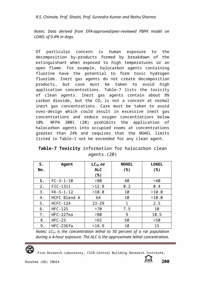
Notes: Data derived from EPA-approved/peer-reviewed PBPK model on LOAEL of 0.4% in dogs.
Of particular concern is human exposure to the decomposition by-products formed by breakdown of the extinguishant when exposed to high temperatures or an open flame. For example,
Fire Research Laboratory, CSIR-Central Building Research Institute, Roorkee (UK) INDIA 197

R.S. Chimote, Prof. Shashi, Prof. Surendra Kumar and Reshu Sharma
halocarbon agents containing fluorine have the potential to form toxic hydrogen fluoride. Inert gas agents do not create decomposition products, but care must be taken to avoid high application concentrations. Table-7 lists the toxicity of clean agents. Inert gas agents contain about 8% carbon dioxide, but the CO2 is not a concern at normal inert gas concentrations. Care must be taken to avoid over-design which could result in excessive inert gas concentrations and reduce oxygen concentrations below 10%. NFPA 2001 (20) prohibits the application of halocarbon agents into occupied rooms at concentrations greater than 24% and requires that the NOAEL limits listed in Table-1 not be exceeded for any clean agent.
Table-7 Toxicity information for halocarbon clean agents.(20)
S. No.
Agent LC50 or ALC(%)
NOAEL(%)
LOAEL(%)
1. FC-3-1-10 >80 40 >402. FIC-1311 >12.8 0.2 0.43. FK-5-1-12 >10.0 10 >10.04. HCFC Blend A 64 10 >10.05. HCFC-124 23-29 1 2.56. HFC-125 >70 7.5 107. HFC-227ea >80 9 10.5 8. HFC-23 >65 50 >50 9. HFC-236fa >18.9 10 15
Notes: LC50 is the concentration lethal to 50 percent of a rat population during a 4-hour exposure. The ALC is the approximate lethal concentration. The cardiac sensitization levels are based on the observance or non-observance of serious heart arrhythmias in a dog. The usual protocol is a 5-minute exposure followed by a challenge with epinephrine. High concentration values are determined with addition of oxygen to prevent asphyxiation.
Table-7 provides information for designers relative to NOAEL and LOAEL percentages for halocarbon clear agents and time for safe exposure for HFC-125, HFC-236fa, HFC-277ea, and FIC-1311. These tables enable designers of clean agent systems to consider methodologies for keeping human exposure to clean agents to a minimum. Methods to protect personnel exposed to clean agents include:
Ensuring that exits are well situated, well marked, and well lighted, adequate number and width to allow rapid egress of all occupants, and are readily accessible with clear and unobstructed aisles or passageways to the exits
Fire Research Laboratory, CSIR-Central Building Research Institute, Roorkee (UK) INDIA 198

Design of clean agent fire extinguishing system as per NFPA 2001 standards with respect to fire hazard scenarios in India
Consider the provision of extra egress doors; specifying that doors are required to swing in the direction of egress travel and to reclose automatically
Providing adequate alarm notification before clean agent discharge
Providing training of personnel to ensure proper identification and response to an alarm; Providing continuous alarms during discharge and agent containment
Providing alarms, locks, signs, and other methods to prevent re-entry to the room during agent containment
Specifying placement of breathing apparatus and room ventilation requirements
Specifying a plan for rescue of anyone who may become trapped within the room or otherwise overexposed to the suppressing agent and its combustion byproducts
Consideration also must be given to the possibility of confusion or disorientation of occupants during discharge. Clean agent discharge may be noisy, and the force of discharge may create reduced visibility, may produce a swirl of dislodged papers or other loose materials, and the low temperature of discharging gas may be a shock to a personnel. Training of responsible personnel is a necessity, and the specification of clean agent systems should not be considered for “at risk” persons, such as in public and patient areas in hospitals and nursing homes.
Clean Agent System Design Considerations for Urban/ Semi-Urban Occupancies in India
The clean agent system design considerations for the halon-alternative fire extinguishing agents that must be planned and designed for urban and semi-urban occupancies in India such that the fire extinguishant containers should not be in the hazardous area and it shall suitably be in a protected location as close as possible to the hazard. Piping and fittings must be of a pressure rating commensurate with expected system pressures, and must be corrosion-resistant. Piping and fittings must be metallic, and the fittings can not be of cast iron and it may be of welded, brazed, or malleable iron. Fire suppression and detection shall be selected/designed to be appropriate for the anticipated class of fires and emerging fire load density pattern/layout with appropriately designed discharge flow rate, particle/droplet size distribution with respect to fire extinguishing efficiency parameters.
An existing detection system may possibly be reused when designing a clean agent system, provided that the characteristics
Fire Research Laboratory, CSIR-Central Building Research Institute, Roorkee (UK) INDIA 199
R.S. Chimote, Prof. Shashi, Prof. Surendra Kumar and Reshu Sharma
of the anticipated fire have not been changed Because local application
has not been found to be effective by the committee responsible for the technical content of NFPA 2001, clean agent systems are to be specified and designed for total flooding of enclosures. The enclosure protected by a clean agent must be rendered amenable to the application and retention of agent by
Arranging for the automatic closing of doors Sealing opening and cracks around doors and windows Clipping down and restraining ceiling tiles and sealing them
where necessary Shutting down supply and return air to the room with dampers
in the ducts to prevent loss of clean agent Attempting to limit loss of clean agent through floor drains,
trenches, pipe penetrations through walls, and other wall and floor penetrations
Shutting down gas or other flammable supplies Shutting down electrical power to energized electrical
components where necessary
Systems must be designed such that the agent containers are not in the hazard area, and are in a protected location as close as possible to the hazard. Piping and fittings must be of a pressure rating commensurate with expected system pressures, and must be corrosion-resistant. Piping and fittings must be metallic, and fittings cannot be cast iron. They can be welded, brazed, or malleable iron. Detection shall be selected to be appropriate for the anticipated fire, as discussed. An existing detection system possibly may be reused when designing a clean agent system for a room currently protected by halon, provided that the characteristics of the anticipated fire have not changed.
Designing Halocarbon Clean Fire Extinguishants Total Fire Suppression Quantitative Requirement
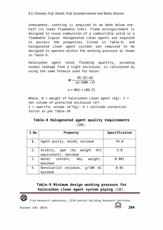
Clean agent systems are designed to extinguish fires either by flame extinguishment or by inerting. For reduction of the flammable concentration in an atmosphere, inerting is required to be done below one-half its lower flammable limit. Flame extinguishment is designed to cease combustion of a combustible solid or a flammable liquid. Halogenated clean agents are required to possess the properties listed in Table-8, and halogenated clean agent systems are required to be designed to operate within the working pressure as shown in Table-9.
Fire Research Laboratory, CSIR-Central Building Research Institute, Roorkee (UK) INDIA 200

Design of clean agent fire extinguishing system as per NFPA 2001 standards with respect to fire hazard scenarios in India
Halocarbon agent total flooding quantity, assuming normal leakage from a tight enclosure, is calculated by using the same formula used for halon:
Where, W = weight of halocarbon clean agent (kg); V = net volume of protected enclosure (m3)S = specific volume (m3/kg); A = altitude correction factor as per Table-10
Table-8 Halogenated agent quality requirements (20).
S.No.
Property Specification
1. Agent purity, mole%, minimum 99.0
2. Acidity, ppm (by weight HCl equivalent), maximum
3.0
3. Water content, %by weight, maximum
0.001
4. Nonvolatile residues, g/100 ml maximum
0.05
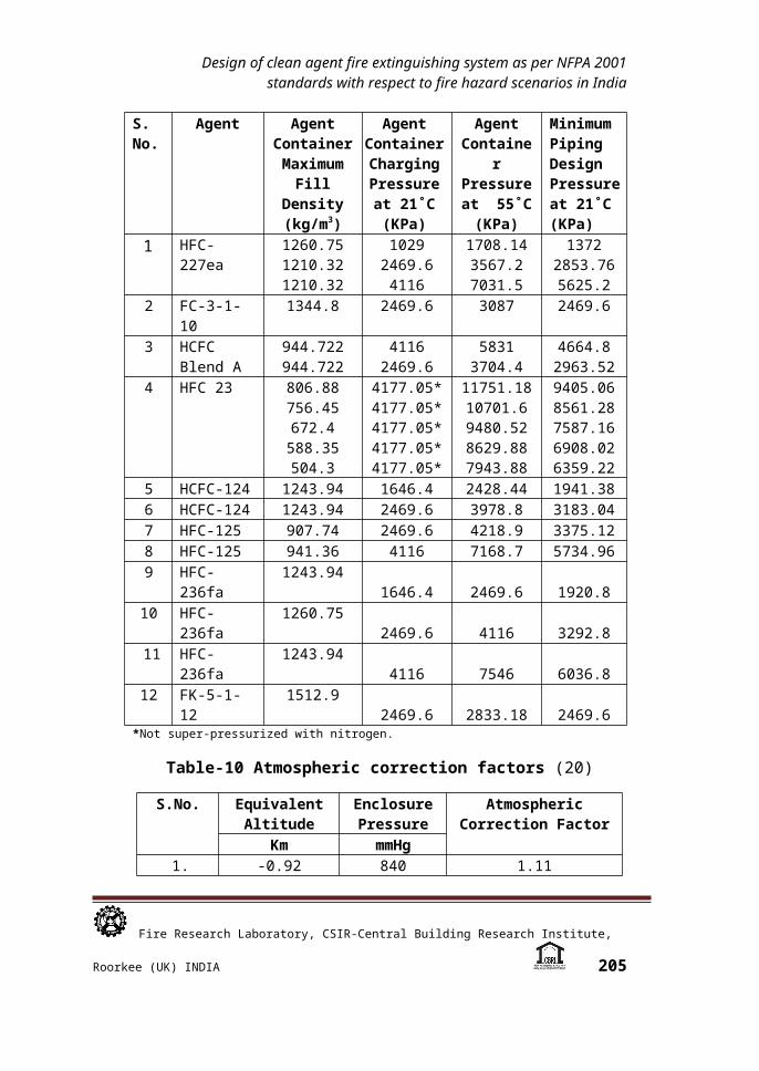
Table-9 Minimum design working pressure for halocarbon clean agent system piping (20).
S.No.
Agent Agent Container Maximum
Fill Density (kg/m3)
Agent Container Charging Pressure at 21˚C (KPa)
Agent Containe
r Pressure at 55˚C (KPa)
Minimum Piping Design Pressure at 21˚C (KPa)
1 HFC-227ea
1260.751210.321210.32
10292469.64116
1708.143567.27031.5
13722853.765625.2
2 FC-3-1-10 1344.8 2469.6 3087 2469.63 HCFC
Blend A 944.722944.722
41162469.6
58313704.4
4664.82963.52
Fire Research Laboratory, CSIR-Central Building Research Institute, Roorkee (UK) INDIA 201
R.S. Chimote, Prof. Shashi, Prof. Surendra Kumar and Reshu Sharma
4 HFC 23 806.88756.45672.4588.35504.3
4177.05*4177.05*4177.05*4177.05*4177.05*
11751.1810701.69480.528629.887943.88
9405.068561.287587.166908.026359.22
5 HCFC-124 1243.94 1646.4 2428.44 1941.386 HCFC-124 1243.94 2469.6 3978.8 3183.047 HFC-125 907.74 2469.6 4218.9 3375.128 HFC-125 941.36 4116 7168.7 5734.969 HFC-
236fa1243.94
1646.4 2469.6 1920.810 HFC-
236fa1260.75
2469.6 4116 3292.811 HFC-
236fa1243.94
4116 7546 6036.812 FK-5-1-12 1512.9 2469.6 2833.18 2469.6
*Not super-pressurized with nitrogen.
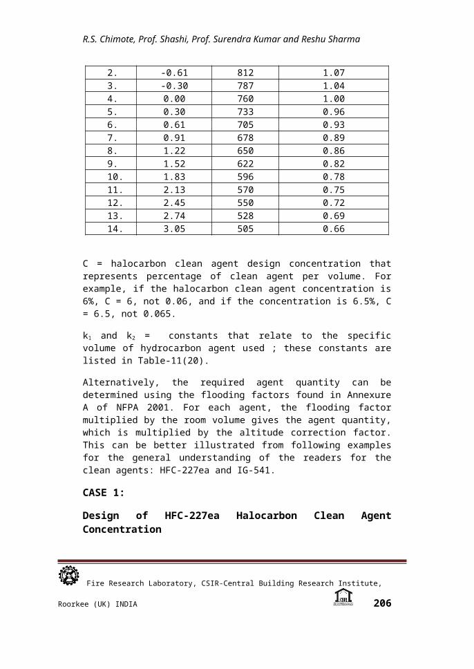
Table-10 Atmospheric correction factors (20)
S.No. Equivalent Altitude
Enclosure Pressure
Atmospheric Correction Factor
Km mmHg1. -0.92 840 1.112. -0.61 812 1.073. -0.30 787 1.044. 0.00 760 1.005. 0.30 733 0.966. 0.61 705 0.937. 0.91 678 0.898. 1.22 650 0.869. 1.52 622 0.8210. 1.83 596 0.7811. 2.13 570 0.7512. 2.45 550 0.7213. 2.74 528 0.6914. 3.05 505 0.66
C = halocarbon clean agent design concentration that represents percentage of clean agent per volume. For example, if the halocarbon clean agent concentration is 6%, C = 6, not 0.06, and if the concentration is 6.5%, C = 6.5, not 0.065.
k1 and k2 = constants that relate to the specific volume of hydrocarbon agent used ; these constants are listed in Table-11(20).
Fire Research Laboratory, CSIR-Central Building Research Institute, Roorkee (UK) INDIA 202
Design of clean agent fire extinguishing system as per NFPA 2001 standards with respect to fire hazard scenarios in India
Alternatively, the required agent quantity can be determined using the flooding factors found in Annexure A of NFPA 2001. For each agent, the flooding factor multiplied by the room volume gives the agent quantity, which is multiplied by the altitude correction factor. This can be better illustrated from following examples for the general understanding of the readers for the clean agents: HFC-227ea and IG-541.
CASE 1:
Design of HFC-227ea Halocarbon Clean Agent Concentration
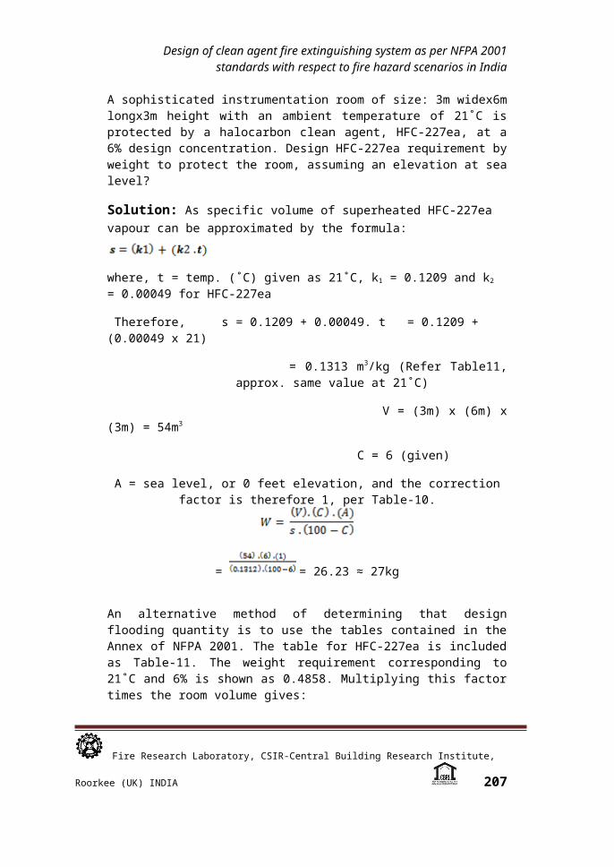
A sophisticated instrumentation room of size: 3m widex6m longx3m height with an ambient temperature of 21˚C is protected by a halocarbon clean agent, HFC-227ea, at a 6% design concentration. Design HFC-227ea requirement by weight to protect the room, assuming an elevation at sea level?
Solution: As specific volume of superheated HFC-227ea vapour
can be approximated by the formula:
where, t = temp. (˚C) given as 21˚C, k1 = 0.1209 and k2 = 0.00049 for HFC-227ea
Therefore, s = 0.1209 + 0.00049. t = 0.1209 + (0.00049 x 21)
= 0.1313 m3/kg (Refer Table11, approx. same value at 21˚C)
V = (3m) x (6m) x (3m) = 54m3
C = 6 (given)
A = sea level, or 0 feet elevation, and the correction factor is therefore 1, per Table-10.
= = 26.23 ≈ 27kg
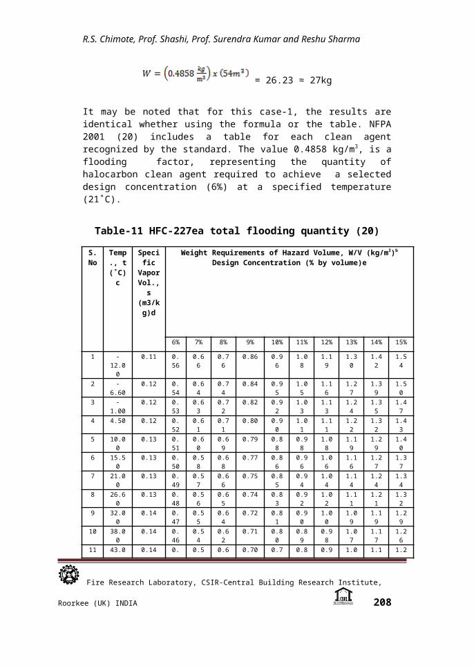
An alternative method of determining that design flooding quantity is to use the tables contained in the Annex of NFPA 2001. The table for HFC-227ea is included as Table-11. The weight requirement corresponding to 21˚C and 6% is shown as 0.4858. Multiplying this factor times the room volume gives:
Fire Research Laboratory, CSIR-Central Building Research Institute, Roorkee (UK) INDIA 203
R.S. Chimote, Prof. Shashi, Prof. Surendra Kumar and Reshu Sharma
= 26.23 ≈ 27kg
It may be noted that for this case-1, the results are identical whether using the formula or the table. NFPA 2001 (20) includes a table for each clean agent recognized by the standard. The value 0.4858 kg/m3, is a flooding factor, representing the quantity of halocarbon clean agent required to achieve a selected design concentration (6%) at a specified temperature (21˚C).
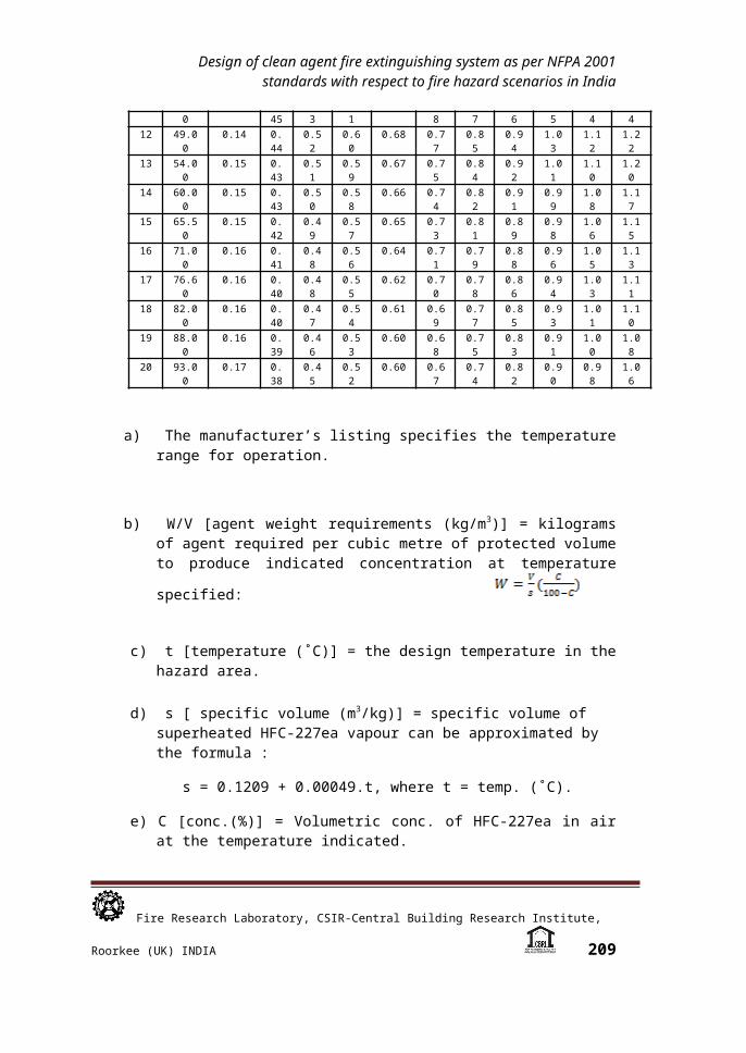
Table-11 HFC-227ea total flooding quantity (20)
S.No
Temp., t (˚C)
c
Specific
Vapor
Vol., s
(m3/kg)d
Weight Requirements of Hazard Volume, W/V (kg/m3)b
Design Concentration (% by volume)e
6% 7% 8% 9% 10% 11% 12% 13% 14% 15%
1 -12.00
0.11 0.56
0.66 0.76 0.86 0.96 1.08 1.19 1.30 1.42 1.54
2 -6.60 0.12 0.54
0.64 0.74 0.84 0.95 1.05 1.16 1.27 1.39 1.50
3 -1.00 0.12 0.53
0.63 0.72 0.82 0.92 1.03 1.13 1.24 1.35 1.47
4 4.50 0.12 0.52
0.61 0.71 0.80 0.90 1.01 1.11 1.22 1.32 1.43
5 10.00 0.13 0.51
0.60 0.69 0.79 0.88 0.98 1.08 1.19 1.29 1.40
6 15.50 0.13 0.50
0.58 0.68 0.77 0.86 0.96 1.06 1.16 1.27 1.37
7 21.00 0.13 0.49
0.57 0.66 0.75 0.85 0.94 1.04 1.14 1.24 1.34
8 26.60 0.13 0.48
0.56 0.65 0.74 0.83 0.92 1.02 1.11 1.21 1.32
9 32.00 0.14 0.47
0.55 0.64 0.72 0.81 0.90 1.00 1.09 1.19 1.29
10 38.00 0.14 0.46
0.54 0.62 0.71 0.80 0.89 0.98 1.07 1.17 1.26
11 43.00 0.14 0.45
0.53 0.61 0.70 0.78 0.87 0.96 1.05 1.14 1.24
12 49.00 0.14 0.44
0.52 0.60 0.68 0.77 0.85 0.94 1.03 1.12 1.22
13 54.00 0.15 0.43
0.51 0.59 0.67 0.75 0.84 0.92 1.01 1.10 1.20
14 60.00 0.15 0.43
0.50 0.58 0.66 0.74 0.82 0.91 0.99 1.08 1.17
15 65.50 0.15 0.42
0.49 0.57 0.65 0.73 0.81 0.89 0.98 1.06 1.15
16 71.00 0.16 0.41
0.48 0.56 0.64 0.71 0.79 0.88 0.96 1.05 1.13
17 76.60 0.16 0.40
0.48 0.55 0.62 0.70 0.78 0.86 0.94 1.03 1.11
Fire Research Laboratory, CSIR-Central Building Research Institute, Roorkee (UK) INDIA 204
Design of clean agent fire extinguishing system as per NFPA 2001 standards with respect to fire hazard scenarios in India
18 82.00 0.16 0.40
0.47 0.54 0.61 0.69 0.77 0.85 0.93 1.01 1.10
19 88.00 0.16 0.39
0.46 0.53 0.60 0.68 0.75 0.83 0.91 1.00 1.08
20 93.00 0.17 0.38
0.45 0.52 0.60 0.67 0.74 0.82 0.90 0.98 1.06
a) The manufacturer’s listing specifies the temperature range for operation.
b) W/V [agent weight requirements (kg/m3)] = kilograms of agent required per cubic metre of protected volume to produce indicated concentration at temperature specified:
c) t [temperature (˚C)] = the design temperature in the hazard area.
d) s [ specific volume (m3/kg)] = specific volume of superheated HFC-227ea vapour can be approximated by the formula :
s = 0.1209 + 0.00049.t, where t = temp. (˚C).
e) C [conc.(%)] = Volumetric conc. of HFC-227ea in air at the temperature indicated.
For other halocarbon clean agents, refer to NFPA 2001.
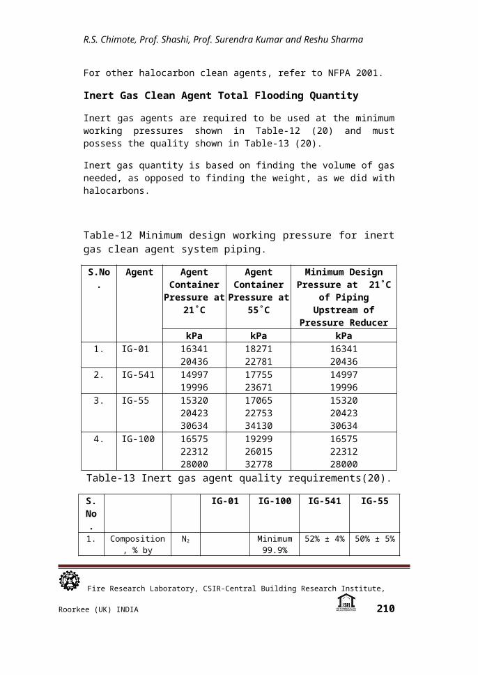
Inert Gas Clean Agent Total Flooding Quantity
Inert gas agents are required to be used at the minimum working pressures shown in Table-12 (20) and must possess the quality shown in Table-13 (20).
Inert gas quantity is based on finding the volume of gas needed, as opposed to finding the weight, as we did with halocarbons.
Table-12 Minimum design working pressure for inert gas clean agent system piping.
S.No.
Agent Agent Container
Pressure at 21˚C
Agent Container
Pressure at 55˚C
Minimum Design Pressure at 21˚C
of Piping Upstream of
Fire Research Laboratory, CSIR-Central Building Research Institute, Roorkee (UK) INDIA 205
R.S. Chimote, Prof. Shashi, Prof. Surendra Kumar and Reshu Sharma
Pressure ReducerkPa kPa kPa
1. IG-01 1634120436
1827122781
1634120436
2. IG-541 1499719996
1775523671
1499719996
3. IG-55 153202042330634
170652275334130
153202042330634
4. IG-100 165752231228000
192992601532778
165752231228000
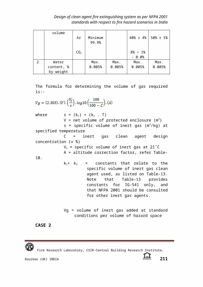
Table-13 Inert gas agent quality requirements(20).
S.No.
IG-01 IG-100 IG-541 IG-55
1. Composition, % by volume
N2
Ar
CO2
Minimum 99.9%
Minimum 99.9%
52% ± 4%
40% ± 4%
8% + 1% - 0.0%
50% ± 5%
50% ± 5%
2. Water content, % by weight
Max.0.005%
Max. 0.005%
Max.0.005%
Max.0.005%
The formula for determining the volume of gas required is:-
where s = (k1) + (k2 . T) V = net volume of protected enclosure (m3)s = specific volume of inert gas (m3/kg) at specified
temperature C = inert gas clean agent design concentration (v
%)Vs = specific volume of inert gas at 21˚CA = altitude correction factor, refer Table-10.k1+ k2 = constants that relate to the specific
volume of inert gas clean agent used, as listed on Table-13. Note that Table-13 provides constants for IG-541 only, and
Fire Research Laboratory, CSIR-Central Building Research Institute, Roorkee (UK) INDIA 206
Design of clean agent fire extinguishing system as per NFPA 2001 standards with respect to fire hazard scenarios in India
that NFPA 2001 should be consulted for other inert gas agents.
Vg = volume of inert gas added at standard conditions per volume of hazard space
CASE 2
Design of IG-541 Inert Gas Clean Agent concentration
A compartment/room of size: 6.06m wide by 15.15m long by 2.42m height with an ambient temperature of 21˚C, is protected by inert gas clean agent IG-541, with a concentration of 34%. Design the minimum volume requirement of IG-541 to protect the compartment/room, assuming an elevation at sea level? (Given: Vs
for IG-541 at 21˚C is 0.675.)
Solution: As specific volume of superheated IG-541 vapour can be approximated by the formula: s = k1 + k2. t,
where t = temperature (˚C); k1 = 0.6271 and k2 = 0.00229 for IG-541
Therefore, s = (0.6271) + (0.00229 x 21)
= 0.675 m3/kg (Refer Table14, approx. same value at 21˚C)
V = (6.06) x (15.15) x (2.42) = 222.17m3
Concentration (%), C = 34 (given)
Vs = 0.675 m3/kg, as per NFPA 2001
A = sea level elevation, and the correction factor is, therefore 1, as per Table-10.
= (2.303) x (222.17) x (1) x (0.1805) x (1) = 92.35 m3
In a manner analogous to the tabular solution presented in Case-1, designers can use Table-14 to obtain a solution. It may be very important to note that the flooding factor corresponding to 21˚C and 34% concentration is 0.416 m3/m3 which when multiplied with 222.17 m3 gives rise to 92.42 m3 of IG-541, which is slightly more
Fire Research Laboratory, CSIR-Central Building Research Institute, Roorkee (UK) INDIA 207
R.S. Chimote, Prof. Shashi, Prof. Surendra Kumar and Reshu Sharma
than that was obtained using the design calculation method, which could be attributed to rounding of logarithmic functions.
Table-14 IG-541 Total flooding quantity
S.No.
Temp. t
Specific Vapor
Volume s
Volume Requirements of Agent per Unit Volume of Hazard, Vagent/Venclosure b
Design Concentration (% by Volume )e
(˚C)c (m3/kg)d
34 38 42 46 50 54 58 62
1 -400.54
0.52
0.60
0.69
0.80
0.87
0.98
1.10
1.22
2 -34.40.55
0.51
0.59
0.67
0.76
0.86
0.96
1.07
1.19
3 -290.56
0.50
0.58
0.66
0.74
0.84
0.94
1.05
1.17
4 -230.57
0.49
0.56
0.64
0.73
0.82
0.92
1.02
1.14
5 -17.70.59
0.48
0.55
0.63
0.71
0.80
0.90
1.00
1.12
6 -120.60
0.47
0.54
0.62
0.70
0.78
0.88
0.98
1.09
7 -6.60.61
0.46
0.53
0.60
0.68
0.77
0.86
0.96
1.07
8 -10.62
0.45
0.52
0.59
0.67
0.75
0.84
0.94
1.05
9 4.440.64
0.44
0.51
0.58
0.65
0.74
0.82
0.92
1.03
10 100.65
0.43
0.50
0.57
0.64
0.72
0.81
0.90
1.01
11 15.550.66
0.42
0.49
0.56
0.63
0.71
0.79
0.89
0.99
12 210.68
0.42
0.48
0.55
0.62
0.69
0.78
0.87
0.97
13 26.60.69
0.41
0.47
0.54
0.61
0.68
0.76
0.85
0.95
14 320.70
0.40
0.46
0.53
0.59
0.67
0.75
0.84
0.93
15 37.70.71
0.39
0.45
0.52
0.58
0.66
0.74
0.82
0.92
16 430.73
0.39
0.45
0.51
0.57
0.65
0.72
0.81
0.90
17 490.74
0.38
0.44
0.50
0.56
0.63
0.71
0.79
0.88
18 54.40.75
0.37
0.43
0.49
0.55
0.62
0.70
0.78
0.87
19 600.76
0.37
0.42
0.48
0.54
0.61
0.69
0.77
0.86
20 65.50.78
0.36
0.42
0.47
0.54
0.60
0.68
0.75
0.84
21 710.79
0.36
0.41
0.47
0.53
0.59
0.66
0.74
0.83
Fire Research Laboratory, CSIR-Central Building Research Institute, Roorkee (UK) INDIA 208
Design of clean agent fire extinguishing system as per NFPA 2001 standards with respect to fire hazard scenarios in India
22 76.60.80
0.35
0.40
0.46
0.52
0.58
0.65
0.73
0.81
23 820.82
0.34
0.40
0.45
0.51
0.57
0.64
0.72
0.80
24 87.70.83
0.34
0.39
0.44
0.50
0.57
0.63
0.71
0.79
25 930.84
0.33
0.38
0.44
0.50
0.56
0.62
0.70
0.78
Note : The manufacturer’s listing specifies the temperature range for operation.
Vg [agent volume requirements (kg/m3)] = Kilogram of agent required per cubic metre of protected volume to produce indicated concentration at temperature specified.
t [temperature (˚C)] = the design temperature in the hazard area.
s [ specific volume (m3/kg) ] = specific volume of superheated IG-541 vapour can be approximated by the formula :
s = 0.6271 + 0.00229t, where t = temperature (˚C).
C [concentration (%)] = Vol. Conc. of IG-541 in air at the temperature indicated.
Note: Vs = the term Vg = ln [100/ (100-C)] gives volume at a rated concentration (%) and temperature to reach air-agent mixture at the end of flooding time in a volume of 1 m3.
Halocarbon and Inert Gas Discharge Time
Halocarbon clean agents must be discharged within 10 sec. Inert gas agents that do not create decomposition products may be discharged within 1 minute. The room must hold the gas for a time sufficient to extinguish a deep-seated fire without re-ignition.
Clean Agent Storage and Nozzle Discharge Arrangement
A clean agent storage arrangement, clean agent nozzles and clean agent discharge are shown in Figure 2 for suppression of fires in a room or compartment.
Fire Research Laboratory, CSIR-Central Building Research Institute, Roorkee (UK) INDIA 209
R.S. Chimote, Prof. Shashi, Prof. Surendra Kumar and Reshu Sharma
Figure 2: A clean agent storage arrangement and discharge from nozzles
Pressure Relief Venting for Clean Agent Systems
NFPA 2001 (20) requires that where clean agent valving arrangements on the pilot piping or on the discharge piping create closed piping arrangements where pressure could increase beyond the pressure rating of the piping, fittings, and nozzles, pressure relief devices are to be installed. The pressure relief devices are required to discharge in such a manner as not to be hazardous to personnel. The NFPA 2001 Annex describes pressure relief isometric diagrams for clean agent cylinders, showing pressure compatibilities for a variety of clean agent storage conditions. The Annex further recommends that pressure relief venting for closed piping sections follow the FSSA Pipe Design Handbook.
Novel and New Water-Based Options for Halon Replacement Options
Three water-based options for Halon replacement are:
1. Water mist system 2. Double-interlocked pre-action Water Mist systems3. Standard automatic water mist systems
CONCLUDING REMARKS
1. The design of new halon systems has been essentially halted as the result of cessation of production of halon in accordance with the Montreal Protocol, which prohibits the manufacture of halogenated agents in countries participating in the agreement. Although pure halon in
Fire Research Laboratory, CSIR-Central Building Research Institute, Roorkee (UK) INDIA 210
Design of clean agent fire extinguishing system as per NFPA 2001 standards with respect to fire hazard scenarios in India
concentrations between 5% and 10% is considered non-toxic to humans during brief exposure, the products of decomposition can be dangerous if breathed.
2. Clean agent systems may be considered as halon system replacements when designed in accordance with NFPA 2001.
3. From Case-1 study, it may be important to note that the value of 0.4858 kg/m3 is a total flooding factor of HFC-227ea fire extinguishing agent representing the quantity of halocarbon clean agent required to achieve a selected design fire extinguishing concentration of 6% at a specified ambient temperature of 21˚C.
4. From Case-2 Study, It may be very important to note that the flooding factor for IG-541 clean agent fire extinguishing agent corresponding to ambient temperature of 21˚C and minimum fire extinguishing 34% concentration is 0.416 m3/m3, which is slightly more than that was obtained using the design calculation method, which could be attributed to rounding of logarithmic functions.
5. The clean agent containers should not be kept/mounted in the hazardous area, and it shall suitably be installed in a protected location as close as possible to the hazard. Piping and fittings must be of a pressure rating commensurate with expected system pressures, and must be corrosion-resistant. Piping and fittings must be metallic, and the fittings can not be of cast iron and it may be of welded, brazed, or malleable iron.
6. Fire suppression and detection shall be selected/ designed to be appropriate for the anticipated class of fires and emerging fire load density pattern/layout with appropriately designed discharge flow rate, particle/droplet size distribution with respect to fire extinguishing efficiency parameters.
7. An existing detection system may possibly be reused when designing a clean agent system, provided that the characteristics of the anticipated fire have not been changed.
8. Clean agents include halocarbon and inert gas agents that are in conformance with NOAEL and EPA guidelines.
Fire Research Laboratory, CSIR-Central Building Research Institute, Roorkee (UK) INDIA 211

R.S. Chimote, Prof. Shashi, Prof. Surendra Kumar and Reshu Sharma
9. Halocarbon agents develop products of decomposition that may be harmful to personnel, hence such agents may be strategically used as per EPA and local government guidelines, rules and regulations prevailing under Protocol Agreement.
ACKNOWLEDGEMENT
Authors are thankful to the Director, CSIR-Central Building Research Institute, Roorkee for according his permission to submit the paper in the Conference on Fire Science & Technology – Research and its Implementation (FIRST-2011) to be organized at CSIR-CBRI, Roorkee on November 3-4, 2011.
REFERENCES
1. Wickham, Robert T. 1972. Engineering and Economic Aspects of Halon Extinguishing Equipment. An Appraisal of Halogenated Fire Extinguishing Agents. National Academy of Sciences, Washington, DC.
2. Jensen, Rolf. 1972. “Halogenated Extinguishing Agent Systems.” Fire Journal. Vol. 66, No. 3. May 1972. Pp 37-39.
3. NFPA 12A, Standard on Halon 1301 Fire Extinguishing Systems.4. NFPA 12B, Standard on Halon 1211 Fire Extinguishing Systems.5. NFPA 12C-T, Standard on Halon 2402 Extinguishing Systems.6. NFPA 75, Standard for the Protection of Electronic Computer
Data Processing Equipment.7. Ford, Charles. 1962. “Overview of Halon 1301 Systems.”
Symposium on the Mechanism of Halogenated Extinguishing Agents. ACS Symposia Series.
8. Bischoff, B.G., “Gaseous Extinguishing Agents,” Heating, Ventilation and Air Conditioning, Oct. 1978.
9. Clarke, D.G., The Toxicity of Bromotrifluoromethane (FE1301) in Animals and Man, Industrial Hygiene Research Laboratory, Imperial Chemical Industries, Alderley Park, Chesire, UK. 1970.
10. Ford, Charles L., “Halon 1301 Fire Extinguishing Agent: Properties and Applications,” Fire Journal, Vol. 64, No. 6, Nov. 1970.
11. Franck, Thomas E., “Clean Room Protection Using Halon 1301,” Fire Journal, Vol. 65, No. 2, Mar. 1971, pp. 77-79.
12. Steinberg, Marshall, “Toxic Hazards from Extinguishing Gasoline Fires Using Halon 1301 Extinguishers in Armored Personnel Carriers,” An Appraisal of Halogenated Fire Extinguishing Agents, National Academy of Sciences, Washington, DC, 1972.
13. Williamson, H.V., “Halon 1301 – Minimum Concentrations for Extinguishing Deep-Seated Fires,” Fire Technology, Vol. 8, No. 4, Nov. 1972.
Fire Research Laboratory, CSIR-Central Building Research Institute, Roorkee (UK) INDIA 212

Design of clean agent fire extinguishing system as per NFPA 2001 standards with respect to fire hazard scenarios in India
14. National Academy of Sciences, “An Appraisal of Halogenated Fire Extinguishing Agents,” Proceedings of a Symposium, 1972.
15. McDaniel, Dale E., “Evaluation of Halon 1301 for Shipboard Use,” An Appraisal of Halogenated Fire Extinguishing Agents, National Academy of Sciences, Washington, DC, 1972.
16. Wiersman, Steve J., “Flow Characteristics of Halon 1301 in Pipelines,” Fire Technology, Vol.14, No.1, Feb. 1978, pp. 5-14.
17. Strasser A., Liebman, I., and Kuchta, J.M. “Methane Flame Extinguishment with Layered Halon or Carbon Dioxide,” Fire Technology, Vol. 10, No. 1, Feb. 1974, pp. 25-34.
18. Robinson, Victor B., “Partial Flooding of Volumes with Halon 1301,” Fire Technology, Vol. 14, No. 2, May 1978, pp. 97-109.
19. Edmonds, Albert, “Use of Halon 1211 in Hand Extinguishers and Local Application Systems,” An Appraisal of Halogenated Fire Extinguishing Agents, National Academy of Sciences, Washington, DC, 1972.
20. NFPA 2001 (2004), Clean Agent Fire Extinguishing Systems, National Fire Protection Association, Quincy, MA 02169.
21. “Carbon Dioxide Fire Extinguishing Systems,” Walter Kidde and Co., Wake Forest, NC, 1981, rev. Aug. 1984.
22. Beiggs, A. A., “Use of Nitrogen-Filled High Expansion Foam to Protect a 500 – Ton Fuel Tank,” Fire Research Note 1074, Fire Research Station, Boreham Wood, Herts, England, Aug. 1977.
23. NFPA 11A, Standard for Medium and High Expansion Foam Systems.
24. NFPA 403, Recommended Practice for Aircraft Rescue and Fire Fighting Services at Airports and Heliports.
25. NFPA 17, Standard for Dry Chemical Extinguishing Systems.26. Guise, A. B., “Extinguishment of Natural Gas Pressure Fires,”
Fire Technology, Vol. 3, No. 3, Aug.1967, pp. 175-193.27. Lee, T. G., and Robertson, A. F., “Extinguishing Effectiveness of
Some Powdered Materials on Hydrocarbon Fires,” Fire Research Abstracts and Reviews, Vol. 2, No. 1, Jan. 1960.
28. Meldrum, D. N., “Combined Use of Foam and Dry Chemical,” NFPA Quarterly, Vol. 56, No. 1, July 1962, pp. 28-34.
29. Underwriters Laboratories Inc., “The Compatibility Relationship Between Mechanical Foam and Dry Chemical Fire Extinguishing Agents,” UL Bulletin of Research No. 54, July 1963, Chicago, IL.
30. Woolhouse, R. A., and Sayers, D. R., “Monnex Compared with Other Potassium-Based Dry Chemicals,” Fire Journal, Vol. 671, No. 1, Jan. 1973, pp. 85-88.
31. Wesson, H. R., “Studies of the Effects of Particle Size on the Flow Characteristics of Dry Chemical,” Fire Technology, Vol. 8, No. 3, Aug. 1972, pp. 173-180.
32. Tuve, R. L., “Light Water and Potassium Bicarbonate Dry Chemical-A New Two Agent Extinguishing System,” NFPA Quarterly, Vol. 58, No. 1, July 1964, pp. 64-69.
Fire Research Laboratory, CSIR-Central Building Research Institute, Roorkee (UK) INDIA 213

R.S. Chimote, Prof. Shashi, Prof. Surendra Kumar and Reshu Sharma
33. Haessler, W. M. 1974. The Extinguishment of Fire. Revised edition. National Fire Protection Association, Quincy, MA.
Fire Research Laboratory, CSIR-Central Building Research Institute, Roorkee (UK) INDIA 214