Design of Circular Concrete Tanks - Islamic...
90
The Islamic University of Gaza Department of Civil Engineering Design of Circular Concrete Tanks Dr. Mohammed Arafa 1
Transcript of Design of Circular Concrete Tanks - Islamic...
The Islamic University of Gaza
Department of Civil Engineering
Design of Circular Concrete Tanks
Dr. Mohammed Arafa
1
Design of Circular Concrete Tanks
Introduction Concrete tanks have been used extensively in municipal and
industrial facilities for several decades.
The design of these structures requires that attention be given
not only to strength requirements, but to serviceability
requirements as well.
A properly designed tank must be able to withstand the
applied loads without cracks that would permit leakage.
2
Design of Circular Concrete Tanks
Introduction
The goal of providing a structurally sound tank that will not leak is
achieved by
Providing proper reinforcement and distribution.
Proper spacing and detailing of construction joints.
Use of quality concrete placed using proper construction
procedures.
3
Design of Circular Concrete Tanks
Introduction
The report by ACI Committee 350 entitled Environmental
Engineering Concrete Structures is essential in understanding
the design of tanks.
4

Design of Circular Concrete Tanks
ACI 350R-01 Report
This report presents recommendations for structural design,
materials, and construction of concrete tanks, reservoirs, and other
structures commonly used in water containment, industrial and
domestic water, and wastewater treatment works, where dense,
impermeable concrete with high resistance to chemical attack is
required.
5

Design of Circular Concrete Tanks
Load Conditions
6
Loading Conditions
The tank may also be subjected to uplift forces from
hydrostatic pressure at the bottom when empty.
It is important to consider all possible loading conditions on
the structure.
Full effects of the soil loads and water pressure must be
designed for without using them to minimize the effects of
each other.
The effects of water table must be considered for the design
loading conditions.
7
Design of Circular Concrete Tanks
Strength Design Method Modification 1 The load factor to be used for lateral liquid
pressure, F, is taken as 1.7 rather than the value of 1.4 specified
in ACI 318.
Modification 2 ACI 350-01 requires that the value of U be
increased by using a multiplier called the sanitary coefficient.
Required strength = Sanitary coefficient x U
where the sanitary coefficient equals:1.3 for flexure
1.65 for direct tension
1.3 for shear beyond that of the capacity provided by the Concrete.
8

Design of Circular Concrete Tanks
Working Stress Design
ACI 350-01 implies in its document that the maximum
allowable stress for Grade 60 (4200 Kg/cm2) reinforcing steel is
2100 Kg/cm2 (0.5fy).
ACI 350 recommends the allowable stress in hoop tension for
Grade 60 (4200 Kg/cm2) reinforcing steel as is 1400 Kg/cm2
(fy/3).
9
Modification according to ACI 350-06
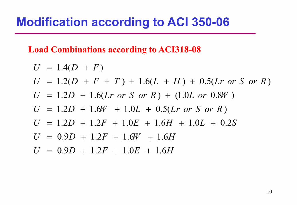
Load Combinations according to ACI318-08
1.4( )
1.2( ) 1.6( ) 0.5( )
1.2 1.6( ) (1.0 0.8 )
1.2 1.6 1.0 0.5( )
1.2 1.2 1.0 1.6 1.0 0.2
U D F
U D F T L H Lr or S or R
U D Lr or S or R L or W
U D W L Lr or S or R
U D F E H L S
U
0.9 1.2 1.6 1.6
0.9 1.2 1.0 1.6
D F W H
U D F E H
10
Modification according to ACI 350-06
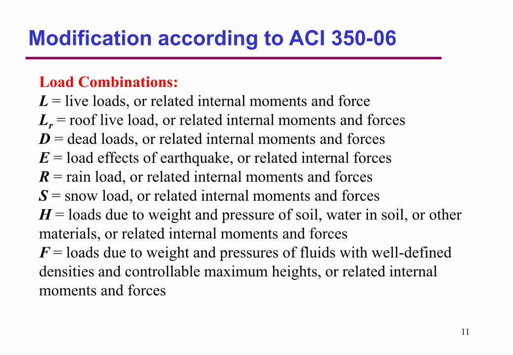
Load Combinations:
L = live loads, or related internal moments and force
Lr = roof live load, or related internal moments and forces
D = dead loads, or related internal moments and forces
E = load effects of earthquake, or related internal forces
R = rain load, or related internal moments and forces
S = snow load, or related internal moments and forces
H = loads due to weight and pressure of soil, water in soil, or other
materials, or related internal moments and forces
F = loads due to weight and pressures of fluids with well-defined
densities and controllable maximum heights, or related internal
moments and forces
11
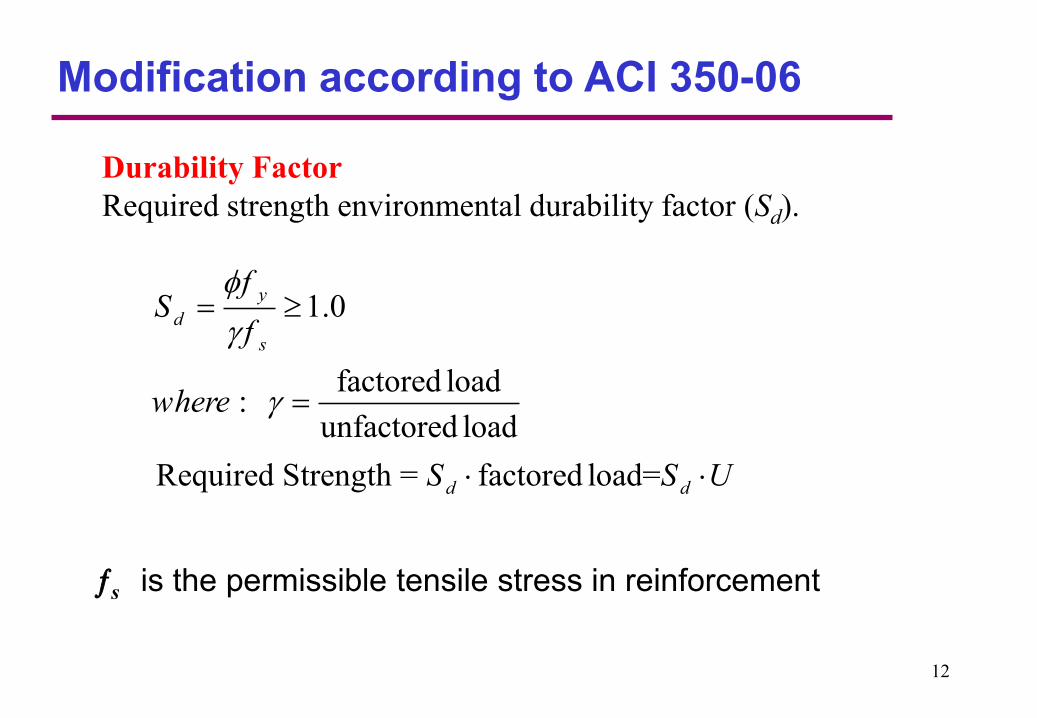
Durability Factor
Required strength environmental durability factor (Sd).
s is the permissible tensile stress in reinforcement
1.0
factored load:
unfactored load
Required Strength = factored load=
y
d
s
d d
fS
f
where
S S U
Modification according to ACI 350-06
12
Design of Circular Concrete Tanks
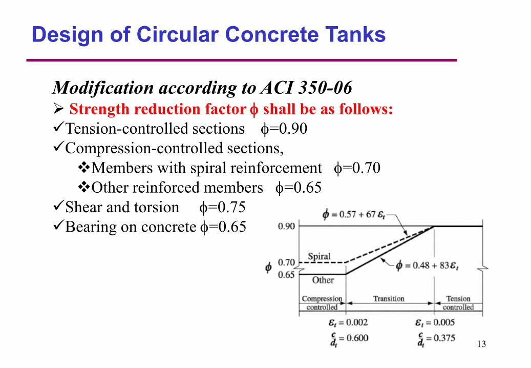
Modification according to ACI 350-06 Strength reduction factor shall be as follows:
Tension-controlled sections =0.90
Compression-controlled sections,
Members with spiral reinforcement =0.70
Other reinforced members =0.65
Shear and torsion =0.75
Bearing on concrete =0.65
13
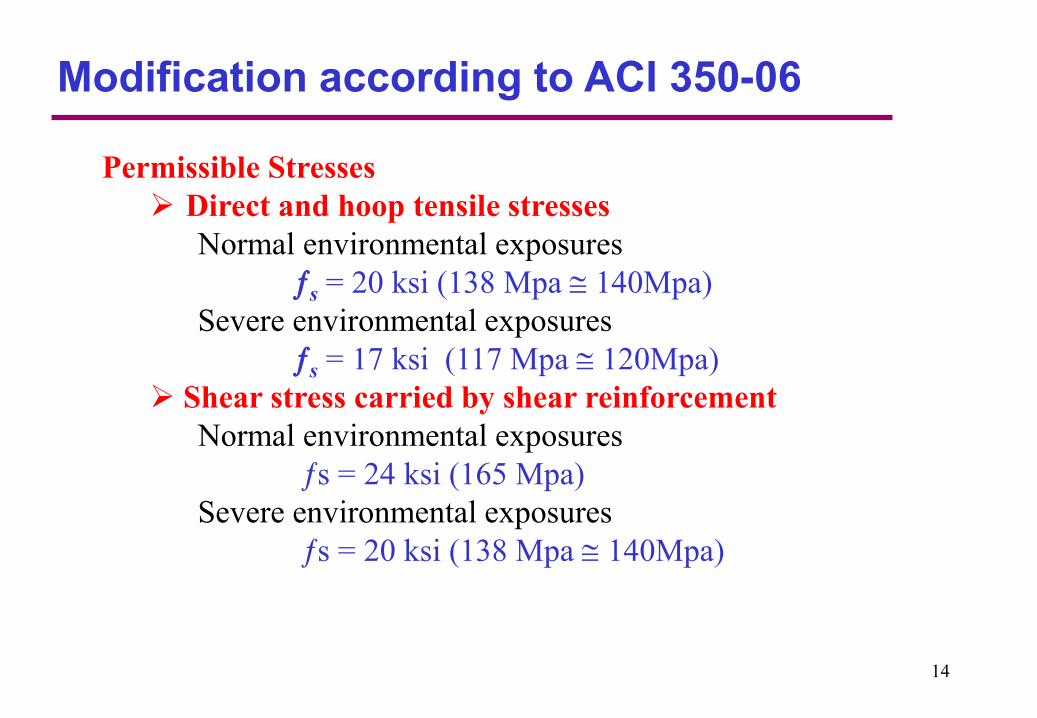
Permissible Stresses
Direct and hoop tensile stresses
Normal environmental exposures
s = 20 ksi (138 Mpa 140Mpa)
Severe environmental exposures
s = 17 ksi (117 Mpa 120Mpa)
Shear stress carried by shear reinforcement
Normal environmental exposures
s = 24 ksi (165 Mpa)
Severe environmental exposures
s = 20 ksi (138 Mpa 140Mpa)
Modification according to ACI 350-06
14
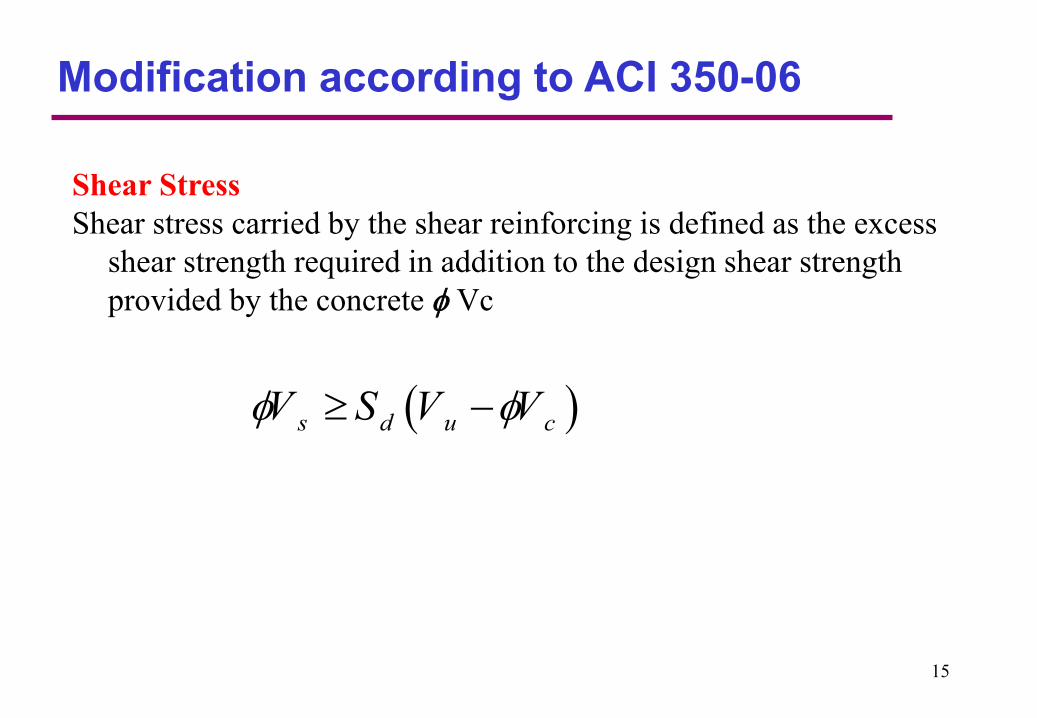
Shear Stress
Shear stress carried by the shear reinforcing is defined as the excess
shear strength required in addition to the design shear strength
provided by the concrete Vc
s d u cV S V V
Modification according to ACI 350-06
15

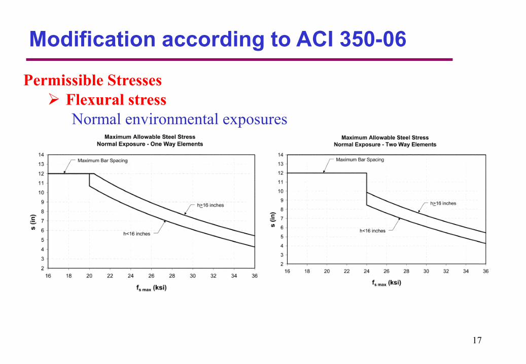
Permissible Stresses
Flexural stress
Normal environmental exposures
Modification according to ACI 350-06
,max
22
32020ksi( 140Mpa) for one way members
4 2 2
24ksi(165Mpa)for two way members.
s
b
f
s d
The following simplified equation can be used
,max2
320
25sf
s
where:
1.2 for h 16 in (40cm).
1.35 for h < 16 in (40cm).
h c
d c
16s = center-to-center spacing of deformed bars
Modification according to ACI 350-06
Permissible Stresses
Flexural stress
Normal environmental exposures
17

Permissible Stresses
Flexural stress
Severe environmental exposures
Modification according to ACI 350-06
,max
22
260 17ksi( 120Mpa) for one way members
4 2 2
20ksi( 140Mpa) for two way members.
s
b
fs d
The following simplified equation can be used
,max2
260
25sf
s
s = center-to-center spacing of deformed bars
18

Modification according to ACI 350-06
Permissible Stresses
Flexural stress
Severe environmental exposures
19
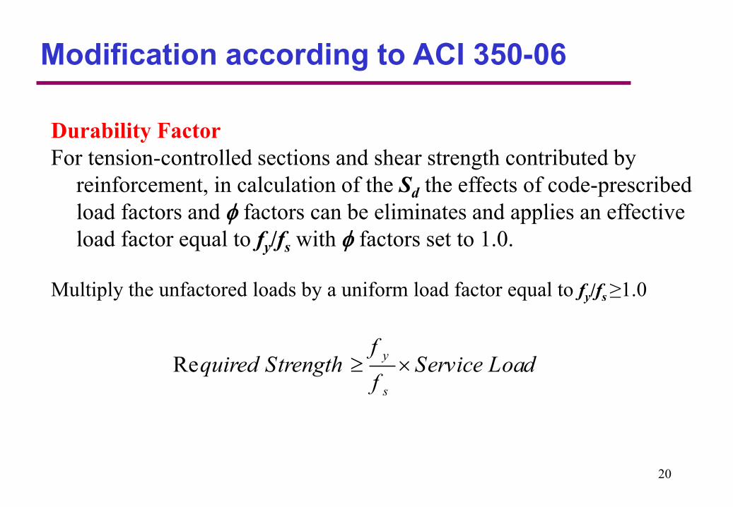
Durability Factor
For tension-controlled sections and shear strength contributed by
reinforcement, in calculation of the Sd the effects of code-prescribed
load factors and factors can be eliminates and applies an effective
load factor equal to fy/fs with factors set to 1.0.
Multiply the unfactored loads by a uniform load factor equal to fy/fs≥1.0
Rey
s
fquired Strength Service Load
f
Modification according to ACI 350-06
20
Wall Thickness
Typically, in the design of reinforced concrete members, the tensile
strength of concrete is ignored.
Any significant cracking in a liquid containing tank is unacceptable.
For this reason, it must be assured that the stress in the concrete from
ring tension is kept at minimum to prevent excessive cracking.
Neither ACI 350 or ACI 318 provide guidelines for the tension
carrying capacity for this condition.
The allowable tensile strength of concrete is usually between 7% an
12% of the compressive strength. A value of 10% of the concrete
strength will be used here.
According to ACI 350, reinforced cast in place concrete walls 3 meter
high or taller, which are in contact with liquid, shall have a minimum
thickness of 30 cm.
21
Wall Thickness
1m
εsh
εc
1m
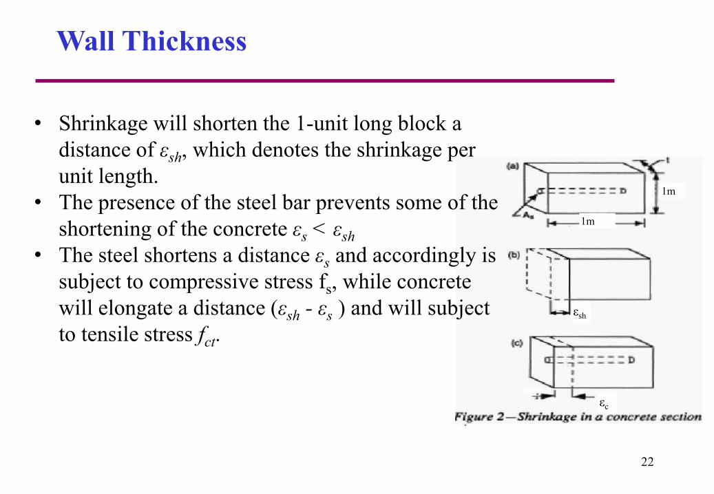
• Shrinkage will shorten the 1-unit long block a
distance of εsh, which denotes the shrinkage per
unit length.
• The presence of the steel bar prevents some of the
shortening of the concrete εs < εsh
• The steel shortens a distance εs and accordingly is
subject to compressive stress fs, while concrete
will elongate a distance (εsh - εs ) and will subject
to tensile stress fct.
22
1m
εsh
εc
1m
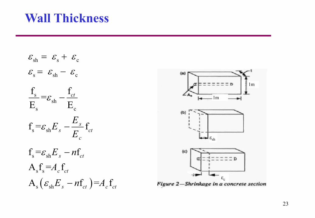
sh s c
s sh c
Wall Thickness
ssh
s c
s sh
f f=
E E
f = f
ct
ss ct
c
EE
E
s sh
s s
s sh
f = f
A f = f
A f = f
s ct
c ct
s ct c ct
E n
A
E n A
23
1m
εsh
εc
1m
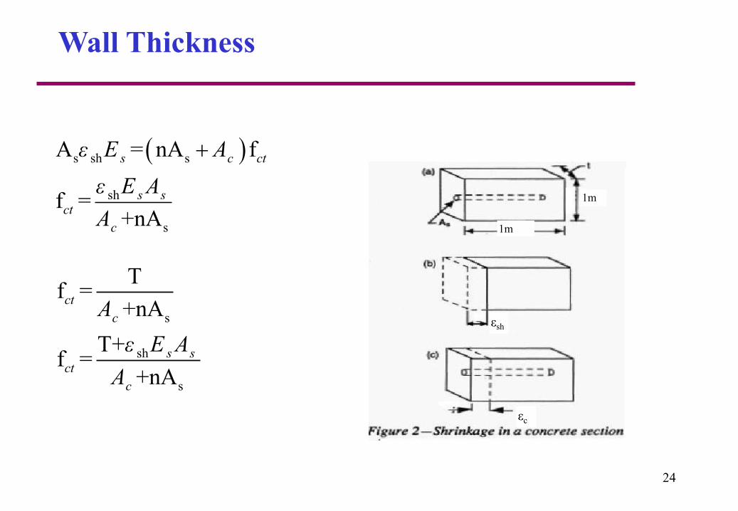
s sh s
sh
s
A = nA f
f =+nA
s c ct
s sct
c
ε E A
ε E A
A
Wall Thickness
s
sh
s
Tf =
+nA
T+f =
+nA
ct
c
s sct
c
A
ε E A
A
24
sh
sh
T+f
f =
100 +nf
f f=
100f f
s
sct
s
s s ct
s ct
Tε E
Tt
ε E nt T
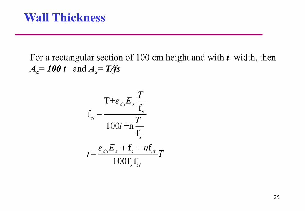
For a rectangular section of 100 cm height and with t width, then
Ac= 100 t and As= T/fs
Wall Thickness
25
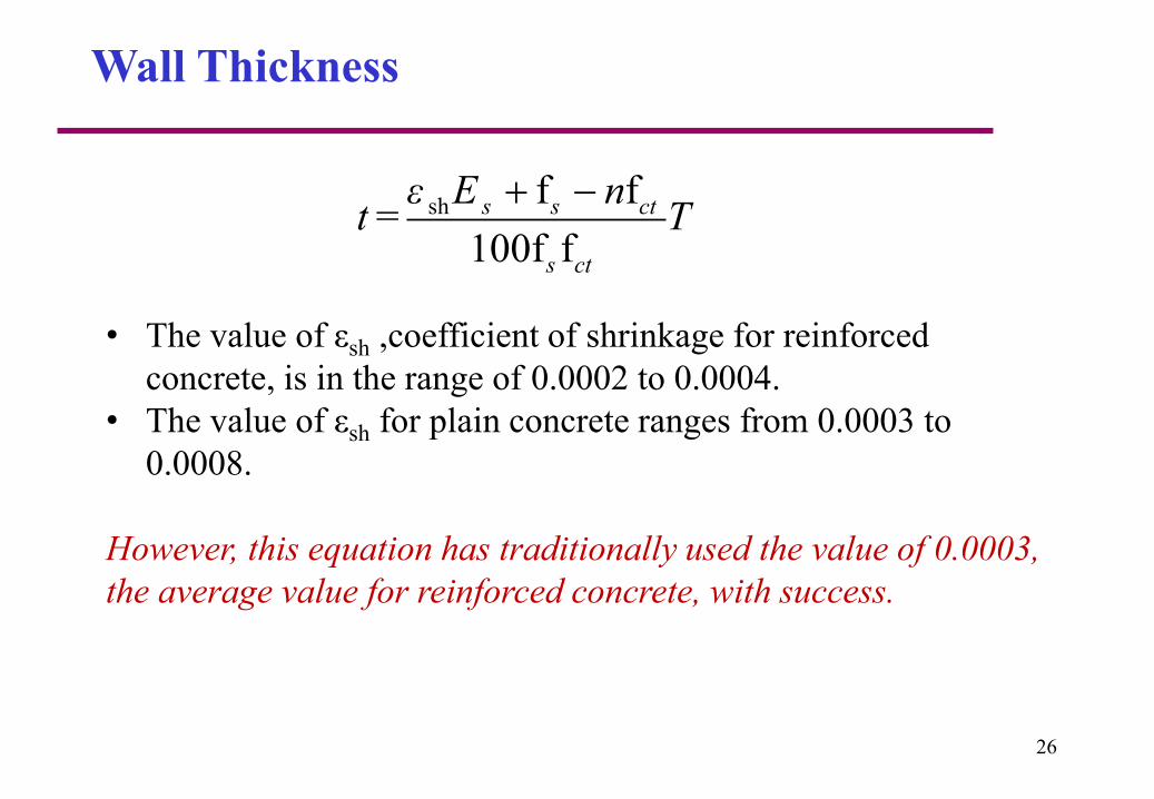
Wall Thickness
• The value of εsh ,coefficient of shrinkage for reinforced
concrete, is in the range of 0.0002 to 0.0004.
• The value of εsh for plain concrete ranges from 0.0003 to
0.0008.
However, this equation has traditionally used the value of 0.0003,
the average value for reinforced concrete, with success.
sh f f=
100f f
s s ct
s ct
ε E nt T
26
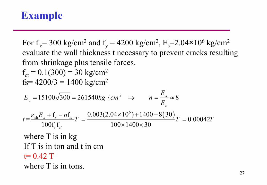
Example
For f c= 300 kg/cm2 and fy = 4200 kg/cm2, Es=2.04×10⁶ kg/cm2
evaluate the wall thickness t necessary to prevent cracks resulting
from shrinkage plus tensile forces.
fct = 0.1(300) = 30 kg/cm2
fs= 4200/3 = 1400 kg/cm2
6
sh0.003(2.04 10 ) 1400 8 30f f
= 0.00042100f f 100 1400 30
s s ct
s ct
ε E nt T T T
215100 300 261540 / 8sc
c
EE kg cm n
E
where T is in kg
If T is in ton and t in cm
t= 0.42 T
where T is in tons. 27

The amount, size, and spacing of reinforcing bars has a great effect
on the extent of cracking.
The amount of reinforcement provided must be sufficient for
strength and serviceability including temperature and shrinkage
effects.
The designer should provide proper details to ensure that cracking
will occur at joints and that joints are properly leak proofed.
The size of reinforcing bars should be chosen recognizing that
cracking can be better controlled by using a larger number of small
diameter bars rather than fewer larger diameter bars.
Spacing of reinforcing bars should be limited to a maximum of 30
cm.
Reinforcement
28
Minimum concrete cover for reinforcement in the tank
wall should be at least 5cm.
The wall thickness should be sufficient to keep the
concrete from cracking. If the concrete does crack, the
ring steel must be able to carry all the ring tension alone.
In circular tanks, the location of horizontal splices should
be staggered. Splices should be staggered horizontally by
not less than one lap length or 90 cm and should not
coincide in vertical arrays more frequently than every
third bar.
Reinforcement
29

Design of Circular Concrete Tanks
Reinforcement
30

Crack Control
95002.5
7560
c
s
s
Cf
S
f
ACI 318- 02
A more practical method which limit the maximum reinforcement spacing
after Cod 95
The Maximum Spacing S of reinforcement closest to the surface in tension
Where
Cc is the clear cover from the nearest surface of concrete in
tension zone to surface of flexural reinforcement.
31

Design of Circular Concrete Tanks
Water Stop Details
32

Design of Circular Concrete Tanks
Types of Wall JointsFree Joint (Sliding joint)
33
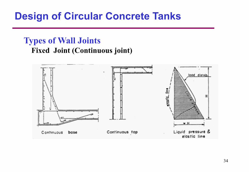
Design of Circular Concrete Tanks
Types of Wall JointsFixed Joint (Continuous joint)
34
Design of Circular Concrete Tanks
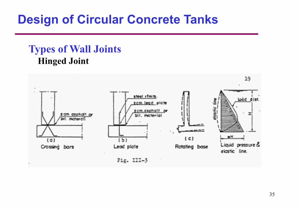
Types of Wall JointsHinged Joint
35
General Notes
For the sliding bottom edge, water pressure is fully resisted
by ring action without developing any bending moment or
shear.
For the hinged bottom edge, ring tension and maximum
moment take place at the middle part of the wall.
36
For the fixed bottom edge, the water pressure will be resisted
by ring action in the horizontal direction and cantilever action
in the vertical direction. The maximum ring and maximum
positive moment will be smaller than for the hinged bottom
edge, while relatively large negative moment will be induced
at the fixed bottom edge of the wall.
General Notes
37

In practice, it would be rare that the base would be fixed
against rotation and such an assumption could lead to an
improperly designed wall. It is more reasonable to
assume that the base is hinged rather than fixed, which
results in a more conservative design.
For walls monolithically cast with the floor it is
recommended to design the section at foot of the wall for
max. negative moment from the total fixation
assumption and max. positive moment and ring tension
from the hinged base assumption.
General Notes
38

Design of Circular Concrete Tanks
Example 1
D=20m
5.5m
The open cylindrical reinforced
concrete tank is 5.5m deep and
20m in diameter. It is required to
determine the internal forces and
to design the wall for the following
cases:
• Bottom edge sliding
• Bottom edge hinged
• Bottom edge fixed
39

Example 1 Bottom edge Sliding
Point T force due to
water pressure
T= xR
0.0 H 0
0.1 H 5.5
0.2 H 11
0.3 H 16.5
0.4 H 22
0.5 H 27.5
0.6 H 33
0.7 H 38.5
0.8 H 44
0.9 H 49.5
1.0H 55
0
0.1
0.2
0.3
0.4
0.5
0.6
0.7
0.8
0.9
1
0 10 20 30 40 50 60
Heig
ht
(*H
)
T ton/m
Ring Tension
max 1.0 5.5 10 55 /T HR t m
40
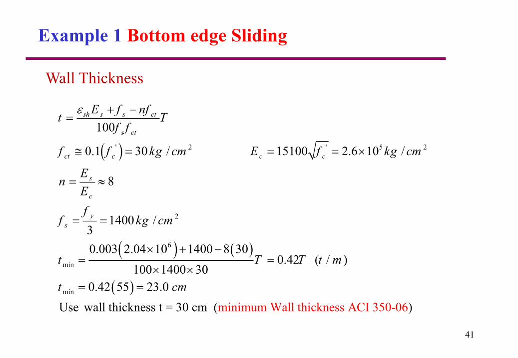
Example 1 Bottom edge Sliding
' 2 ' 5 2
2
6
min
min
100
0.1 30 / 15100 2.6 10 /
8
1400 /3
0.003 2.04 10 1400 8 300.42 ( / )
100 1400 30
0.42 55 23.0
U mise wall thickness t = 30 cm i u( n m m
sh s s ct
s ct
ct c c c
s
c
y
s
E f nft T
f f
f f kg cm E f kg cm
En
E
ff kg cm
t T T t m
t cm
Wall thickness ACI 350-06)
Wall Thickness
41

Example 1 Bottom edge Sliding
3 3 32
2
2
55 10 55 10 154 1040.8 /
0.9 4200 0.9 4200 0.9 4200
20.4 / (on each side of the wall)
use 14 14 mm at each side provided 21.
1.7 1.65 2
6
.8
/
us
y
TA cm m
f
cm m
cm m
32
2
2
1.7 1.65 27.5 1020.4 /
0.9 4200
10.2 / (on each side of the wall)
use 14 10 mm at each side provided 10.9 /
us
y
TA cm m
f
cm m
cm m
Horizontal Reinforcement ACI 350.01
At the bottom T=55 ton
At 0.5 H from the bottom T=27.5 ton
42
Example 1 Bottom edge Sliding
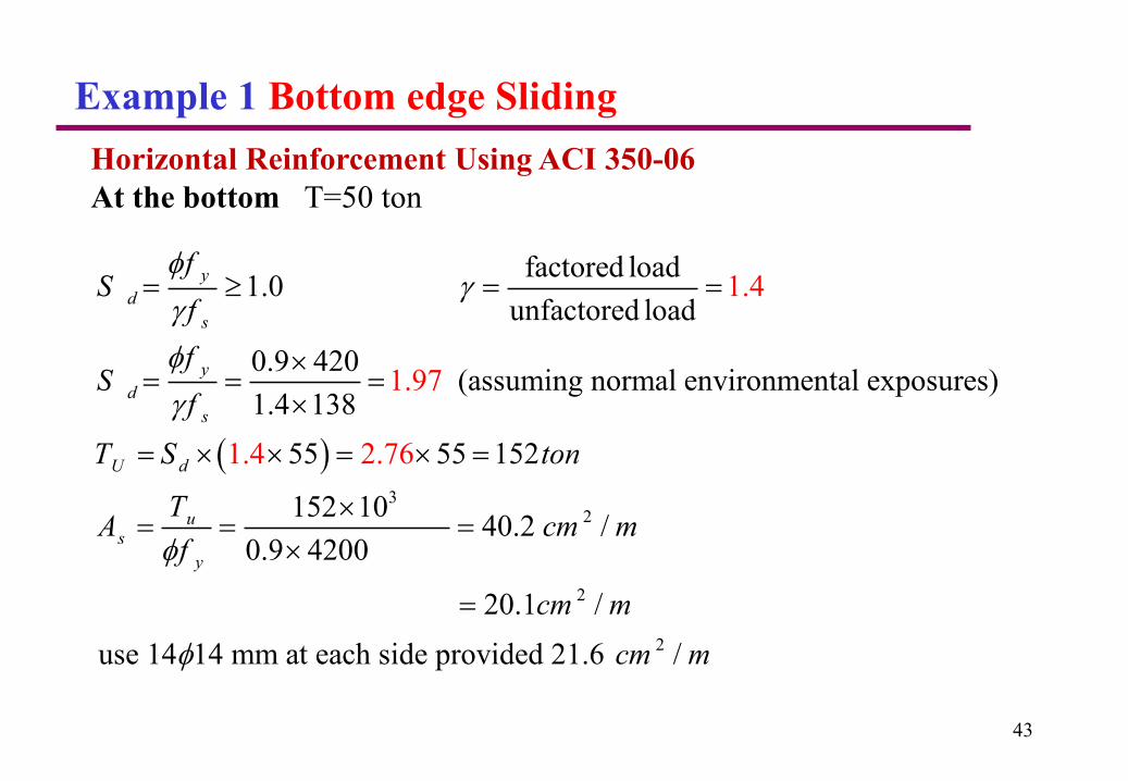
Horizontal Reinforcement Using ACI 350-06
At the bottom T=50 ton
3
2
2
factored load1.0
unfactored load
0.9 420(assuming normal environmen
1.4
1.97
1.4 2
tal exposures)1.4 138
55 55 152
152 104
.
0.2 /0.9 4200
20.1 /
use 14 1
7
4 mm a
6
y
d
s
y
d
s
U d
us
y
fS
f
fS
f
T S ton
TA cm m
f
cm m
2t each side provided 21.6 /cm m
43
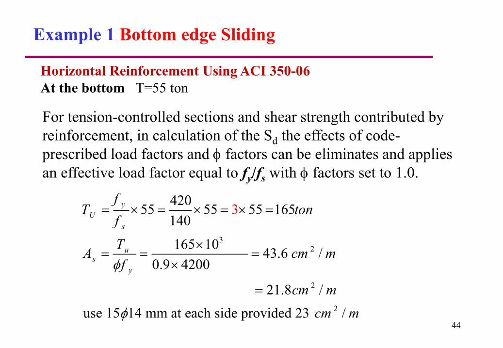
Example 1 Bottom edge Sliding
Horizontal Reinforcement Using ACI 350-06
At the bottom T=55 ton
For tension-controlled sections and shear strength contributed by
reinforcement, in calculation of the Sd the effects of code-
prescribed load factors and factors can be eliminates and applies
an effective load factor equal to fy/fs with factors set to 1.0.
32
2
2
42055 55 55 165
140
165 1043.6 /
0.9 4200
21.8 /
use 15 14 mm at each side provided 23
3
/
y
U
s
us
y
fT ton
f
TA cm m
f
cm m
cm m
44
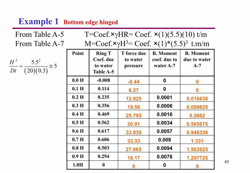
Example 1 Bottom edge hinged
Point Ring T
Coef. due
to water
Table A-5
T force due
to water
pressure
B. Moment
coef. due to
water A-7
B. Moment
due to water
A-7
0.0 H -0.008 -0.44 0 0
0.1 H 0.114 6.27 0 0
0.2 H 0.235 12.925 0.0001 0.016638
0.3 H 0.356 19.58 0.0006 0.099825
0.4 H 0.469 25.795 0.0016 0.2662
0.5 H 0.562 30.91 0.0034 0.565675
0.6 H 0.617 33.935 0.0057 0.948338
0.7 H 0.606 33.33 0.008 1.331
0.8 H 0.503 27.665 0.0094 1.563925
0.9 H 0.294 16.17 0.0078 1.297725
1.0H 0 0 0 0
From Table A-5 T=Coef.×HR= Coef. ×(1)(5.5)(10) t/m
From Table A-7 M=Coef.×H3= Coef. ×(1)*(5.5)3 t.m/m
2 25.55
20 0.3
H
Dt
45
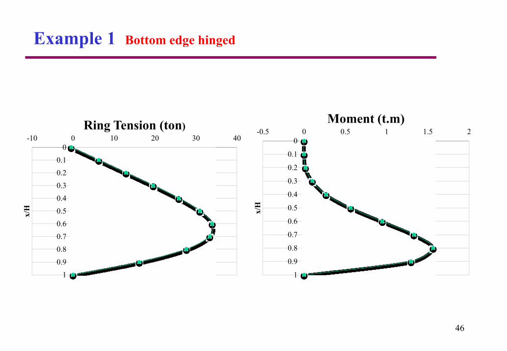
Example 1 Bottom edge hinged
46
0
0.1
0.2
0.3
0.4
0.5
0.6
0.7
0.8
0.9
1
-10 0 10 20 30 40
x/H
Ring Tension (ton)
0
0.1
0.2
0.3
0.4
0.5
0.6
0.7
0.8
0.9
1
-0.5 0 0.5 1 1.5 2
x/H
Moment (t.m)

Example 1 Bottom edge Fixed
Point Ring T
Coef. due
to water
Table A-1
T force due
to water
pressure
B. Moment
coef. due to
water A-2
B. Moment
due to water
A-7
0.0 H 0.025 1.375 0 0
0.1 H 0.137 7.535 0.0002 0.0333
0.2 H 0.245 13.475 0.0008 0.133
0.3 H 0.346 19.03 0.0016 0.266
0.4 H 0.428 23.54 0.0029 0.483
0.5 H 0.477 26.235 0.0046 0.765
0.6 H 0.469 25.795 0.0059 0.982
0.7 H 0.398 21.89 0.0059 0.982
0.8 H 0.259 14.245 0.0028 0.466
0.9 H 0.092 5.06 -0.0058 -0.965
1.0H 0 0 -0.0222 -3.694
From Table A-1 T=Coef.*HR= Coef. *(1)(5.5)(10) t/m
From Table A-2 M=Coef.* H3= Coef. *(1)*(5.5)3 t.m/m
2 25.55
20 0.3
H
Dt
47

Design of Circular Concrete Tanks
Example 1 Bottom edge Fixed
48
0
0.1
0.2
0.3
0.4
0.5
0.6
0.7
0.8
0.9
1
0 5 10 15 20 25 30
x/H
Ring Tension (ton)
0
0.1
0.2
0.3
0.4
0.5
0.6
0.7
0.8
0.9
1
-4 -3 -2 -1 0 1 2
x/H
Moment (t.m)
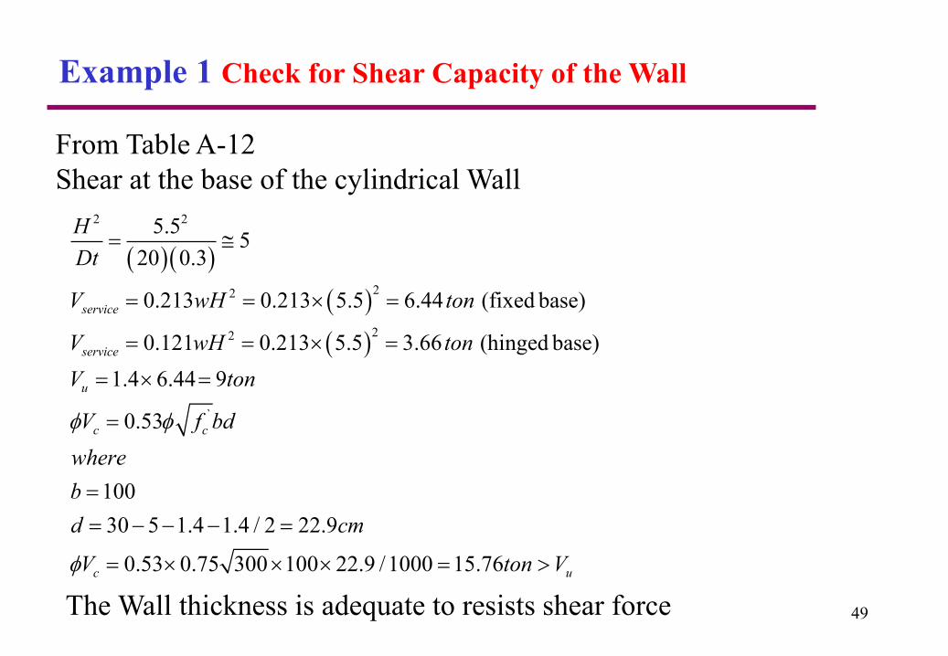
Example 1 Check for Shear Capacity of the Wall
From Table A-12
Shear at the base of the cylindrical Wall
2 2
22
22
`
5.55
20 0.3
0.213 0.213 5.5 6.44 (fixed base)
0.121 0.213 5.5 3.66 (hinged base)
1.4 6.44 9
0.53
100
30 5 1.4 1.4 / 2 22.9
0.53 0.75 300 100 22.9 /
service
service
u
c c
c
H
Dt
V wH ton
V wH ton
V ton
V f bd
where
b
d cm
V
1000 15.76 uton V
49The Wall thickness is adequate to resists shear force

For Water tank members, the area of shrinkage and
temperature reinforcement shall provide at least the ratios
of reinforcement area to gross concrete area shown in the
following Table.
Concrete sections that are at least 24 in (60cm). may have
the minimum shrinkage and temperature reinforcement
based on a 12 in (30cm). concrete layer at each face.
The reinforcement in the bottom of base slabs in contact
with soil may be reduced to 50 percent of that required in
the Table.
50
Minimum Shrinkage and Temp. Reinforcement
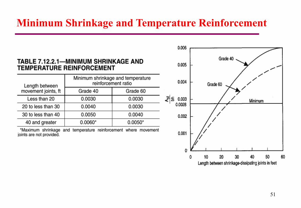
Minimum Shrinkage and Temperature Reinforcement
51
52
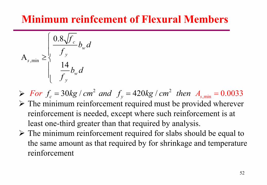
Minimum reinfcement of Flexural Members
,min
0.8
A14
c
w
y
s
w
y
fb d
f
b df
The minimum reinforcement required must be provided wherever
reinforcement is needed, except where such reinforcement is at
least one-third greater than that required by analysis.
The minimum reinforcement required for slabs should be equal to
the same amount as that required by for shrinkage and temperature
reinforcement
2
,min
230 / 420 / 0.0033c y sf kg cm and f kg cm theFo nr A
53
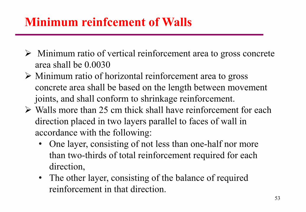
Minimum reinfcement of Walls
Minimum ratio of vertical reinforcement area to gross concrete
area shall be 0.0030
Minimum ratio of horizontal reinforcement area to gross
concrete area shall be based on the length between movement
joints, and shall conform to shrinkage reinforcement.
Walls more than 25 cm thick shall have reinforcement for each
direction placed in two layers parallel to faces of wall in
accordance with the following:
• One layer, consisting of not less than one-half nor more
than two-thirds of total reinforcement required for each
direction,
• The other layer, consisting of the balance of required
reinforcement in that direction.
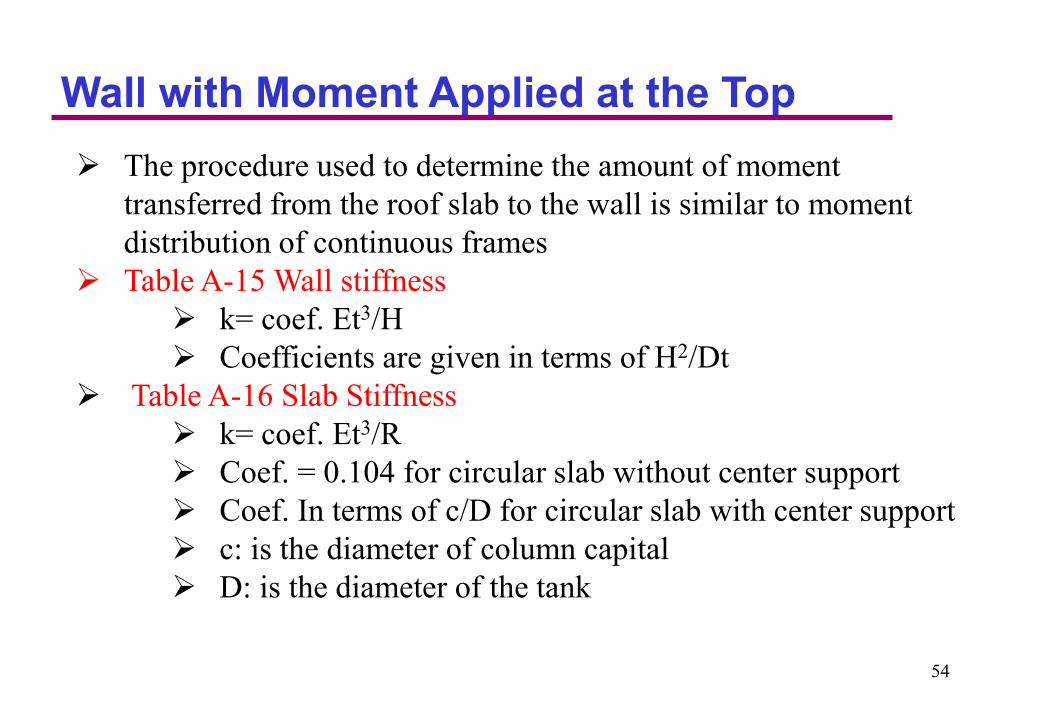
Wall with Moment Applied at the Top
The procedure used to determine the amount of moment
transferred from the roof slab to the wall is similar to moment
distribution of continuous frames
Table A-15 Wall stiffness
k= coef. Et3/H
Coefficients are given in terms of H2/Dt
Table A-16 Slab Stiffness
k= coef. Et3/R
Coef. = 0.104 for circular slab without center support
Coef. In terms of c/D for circular slab with center support
c: is the diameter of column capital
D: is the diameter of the tank
54
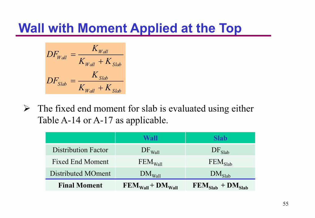
Wall with Moment Applied at the Top
The fixed end moment for slab is evaluated using either
Table A-14 or A-17 as applicable.
Wall
Wall
Wall Slab
Slab
Slab
Wall Slab
KDF
K K
KDF
K K
Wall Slab
Distribution Factor DFWall DFSlab
Fixed End Moment FEMWall FEMSlab
Distributed MOment DMWall DMSlab
Final Moment FEMWall + DMWall FEMSlab + DMSlab
55

Wall with Moment Applied at the Top
Calculation of ring Tension forces in the wall
1. Calculate the ring tension for free fixed condition due to
fluid pressure using Table A-1
2. Calculate the ring tension caused by applied moment at
the top of the wall using Table A-10
3. The final ring Tension are obtained by summing 1 and 2
56
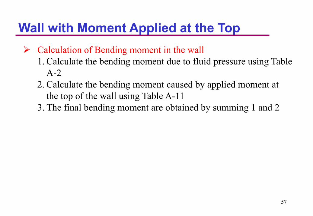
Wall with Moment Applied at the Top
Calculation of Bending moment in the wall
1. Calculate the bending moment due to fluid pressure using Table
A-2
2. Calculate the bending moment caused by applied moment at
the top of the wall using Table A-11
3. The final bending moment are obtained by summing 1 and 2
57
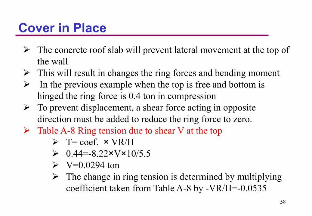
Cover in Place
The concrete roof slab will prevent lateral movement at the top of
the wall
This will result in changes the ring forces and bending moment
In the previous example when the top is free and bottom is
hinged the ring force is 0.4 ton in compression
To prevent displacement, a shear force acting in opposite
direction must be added to reduce the ring force to zero.
Table A-8 Ring tension due to shear V at the top
T= coef. × VR/H
0.44=-8.22×V×10/5.5
V=0.0294 ton
The change in ring tension is determined by multiplying
coefficient taken from Table A-8 by -VR/H=-0.0535
58
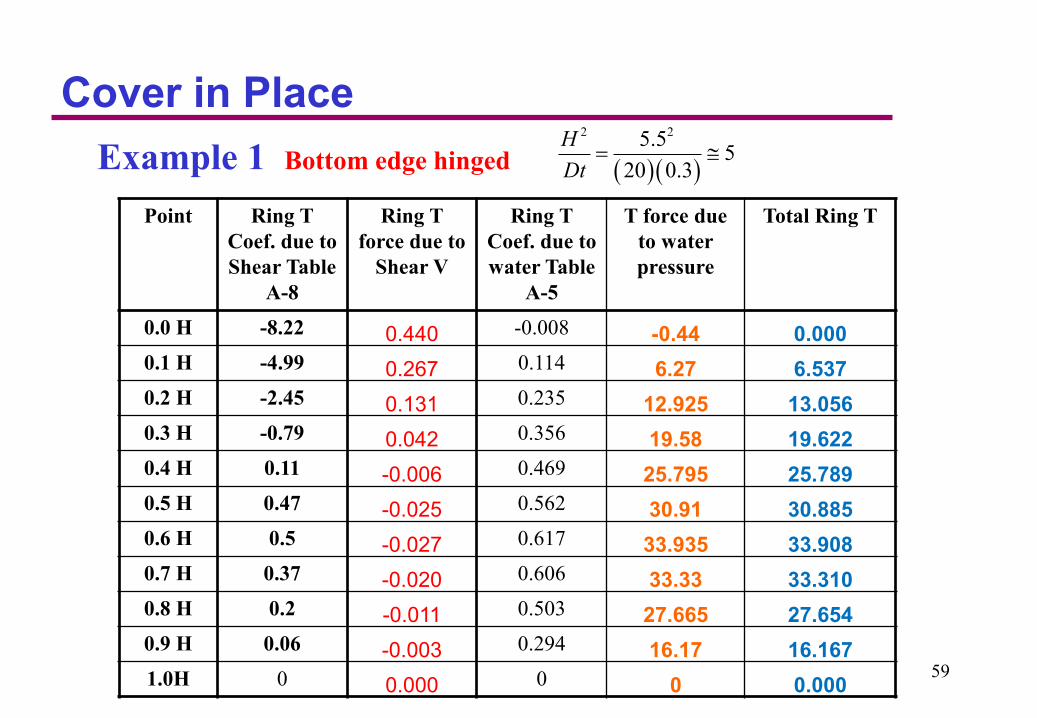
Cover in Place
Example 1 Bottom edge hinged
Point Ring T
Coef. due to
Shear Table
A-8
Ring T
force due to
Shear V
Ring T
Coef. due to
water Table
A-5
T force due
to water
pressure
Total Ring T
0.0 H -8.22 0.440 -0.008 -0.44 0.000
0.1 H -4.99 0.267 0.114 6.27 6.537
0.2 H -2.45 0.131 0.235 12.925 13.056
0.3 H -0.79 0.042 0.356 19.58 19.622
0.4 H 0.11 -0.006 0.469 25.795 25.789
0.5 H 0.47 -0.025 0.562 30.91 30.885
0.6 H 0.5 -0.027 0.617 33.935 33.908
0.7 H 0.37 -0.020 0.606 33.33 33.310
0.8 H 0.2 -0.011 0.503 27.665 27.654
0.9 H 0.06 -0.003 0.294 16.17 16.167
1.0H 0 0.000 0 0 0.000
2 25.55
20 0.3
H
Dt
59

Cover in Place
The change in ring forces and bending moment from restraint of
the roof are relatively small
Loading condition 1 will not practically significantly be changed.
60
Example 2
61
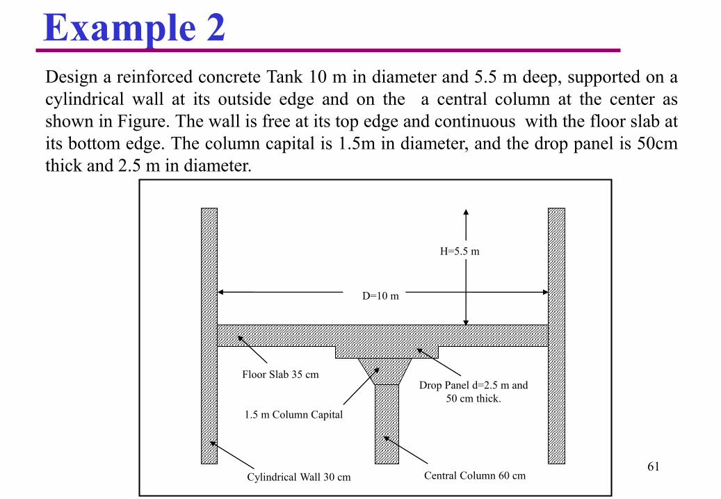
Design a reinforced concrete Tank 10 m in diameter and 5.5 m deep, supported on a
cylindrical wall at its outside edge and on the a central column at the center as
shown in Figure. The wall is free at its top edge and continuous with the floor slab at
its bottom edge. The column capital is 1.5m in diameter, and the drop panel is 50cm
thick and 2.5 m in diameter.
D=10 m
H=5.5 m
Central Column 60 cmCylindrical Wall 30 cm
1.5 m Column Capital
Drop Panel d=2.5 m and
50 cm thick.
Floor Slab 35 cm
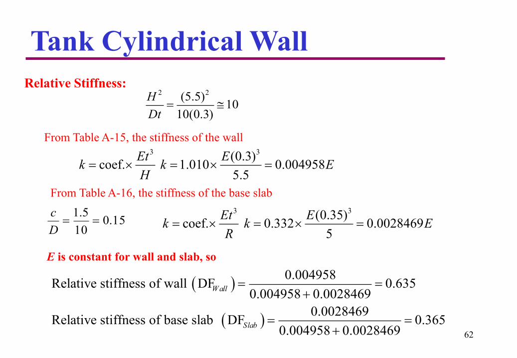
Tank Cylindrical Wall
Relative Stiffness:2 2(5.5)
1010(0.3)
H
Dt
From Table A-15, the stiffness of the wall3 3(0.3)
coef. 1.010 0.0049585.5
Et Ek k E
H
From Table A-16, the stiffness of the base slab
15.010
5.1
D
c 3 3(0.35)coef. 0.332 0.0028469
5
Et Ek k E
R
E is constant for wall and slab, so
0.004958Relative stiffness of wall DF 0.635
0.004958 0.0028469
0.0028469Relative stiffness of base slab DF 0.365
0.004958 0.0028469
Wall
Slab
62

Tank Cylindrical Wall
Service Fixed end moment at base of the wall, using Table A-2 for 2
10H
Dt
3 3coef. 0.0122 (1)(5.5) 2.03 . /M H ton m m
(Tension inside of the wall)
Service Fixed end moment at base slab edge, using Table A-17 for
15.010
5.1
D
c
2
2
coef. , coef. 0.049
1 5.5 0.35 2.5 6.375 /
0.049 6.375 (5) 7.8 . /
M PR
P t m
M t m m
63
6.375kN/m

Tank Cylindrical Wall
Wall Slab
Distribution Factor 0.635 0.365
F.E.M. 2.03 -7.8
Distribution Moment 3.66 2.10
Final Moment 5.7 -5.7
Moment distribution between wall and base slab
64
2.03 t.m/m
7.8 t.m/m

Tank Cylindrical Wall
Moment distribution between wall and base slab
65
factored load1.0
unfactored load
0.9 420(assuming normal environmental exp
1.4
For
os
Ring Tension
1.97
1.4 1.97 1.4 2.8
For Flexural Mom
ures)1.4 138
ent
y
d
s
y
d
s
U d Service Service Service
fS
f
fS
f
T S T T T
S
0.9 420(assuming normal environmental e1.64
1.4
xposures)1.4 16
1.64
5
1.4 2.3
y
d
s
U d Service Service Service
f
f
T S T T T
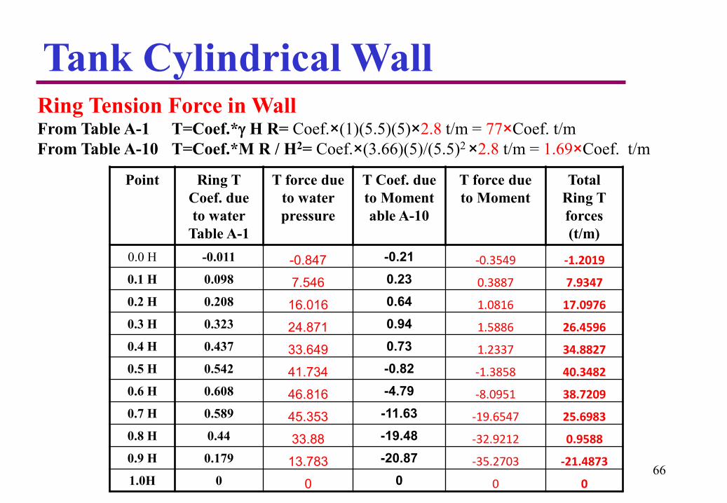
Tank Cylindrical WallRing Tension Force in WallFrom Table A-1 T=Coef.* H R= Coef.×(1)(5.5)(5)×2.8 t/m = 77×Coef. t/m
From Table A-10 T=Coef.*M R / H2= Coef.×(3.66)(5)/(5.5)2 ×2.8 t/m = 1.69×Coef. t/m
Point Ring T
Coef. due
to water
Table A-1
T force due
to water
pressure
T Coef. due
to Moment
able A-10
T force due
to Moment
Total
Ring T
forces
(t/m)
0.0 H -0.011 -0.847 -0.21 -0.3549 -1.2019
0.1 H 0.098 7.546 0.23 0.3887 7.9347
0.2 H 0.208 16.016 0.64 1.0816 17.0976
0.3 H 0.323 24.871 0.94 1.5886 26.4596
0.4 H 0.437 33.649 0.73 1.2337 34.8827
0.5 H 0.542 41.734 -0.82 -1.3858 40.3482
0.6 H 0.608 46.816 -4.79 -8.0951 38.7209
0.7 H 0.589 45.353 -11.63 -19.6547 25.6983
0.8 H 0.44 33.88 -19.48 -32.9212 0.9588
0.9 H 0.179 13.783 -20.87 -35.2703 -21.4873
1.0H 0 0 0 0 066
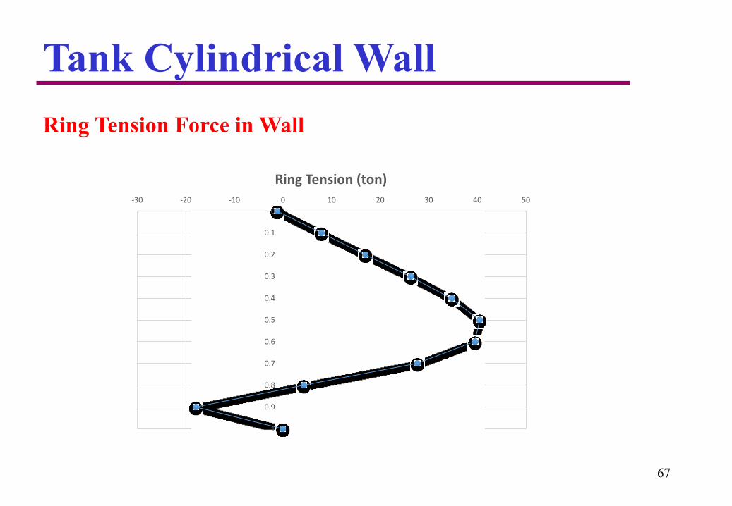
Tank Cylindrical Wall
67
Ring Tension Force in Wall
0
0.1
0.2
0.3
0.4
0.5
0.6
0.7
0.8
0.9
1
-30 -20 -10 0 10 20 30 40 50
Ring Tension (ton)
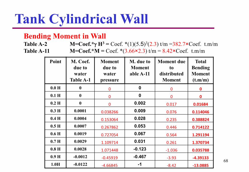
Tank Cylindrical WallBending Moment in WallTable A-2 M=Coef.* H3 = Coef. *(1)(5.5)3(2.3) t/m =382.7×Coef. t.m/m
Table A-11 M=Coef.*M = Coef. *(3.66×2.3) t/m = 8.42×Coef. t.m/m
Point M. Coef.
due to
water
Table A-1
Moment
due to
water
pressure
M. due to
Moment
able A-11
Moment due
to
distributed
Moment
Total
Bending
Moment
(t.m/m)
0.0 H 0 0 0 0 0
0.1 H 0 0 0 0 0
0.2 H 0 0 0.002 0.017 0.01684
0.3 H 0.0001 0.038266 0.009 0.076 0.114046
0.4 H 0.0004 0.153064 0.028 0.235 0.388824
0.5 H 0.0007 0.267862 0.053 0.446 0.714122
0.6 H 0.0019 0.727054 0.067 0.564 1.291194
0.7 H 0.0029 1.109714 0.031 0.261 1.370734
0.8 H 0.0028 1.071448 -0.123 -1.036 0.035788
0.9 H -0.0012 -0.45919 -0.467 -3.93 -4.39133
1.0H -0.0122 -4.66845 -1 -8.42 -13.088568
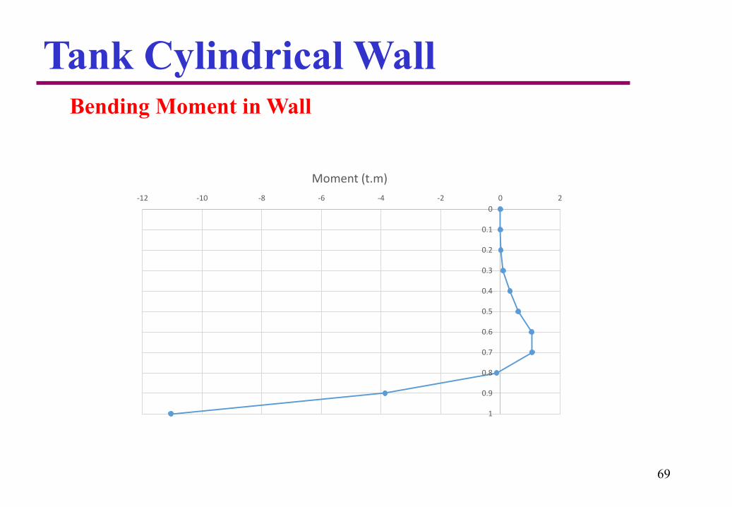
Tank Cylindrical WallBending Moment in Wall
69
0
0.1
0.2
0.3
0.4
0.5
0.6
0.7
0.8
0.9
1
-12 -10 -8 -6 -4 -2 0 2
Moment (t.m)

Tank Cylindrical WallCheck for minimum thickness of the wall due to ring tension:
70
6
40.34Max. Ring tension at service load 14.4
2.8
100
0.003 2.04 10 1400 8 300.00042 0.42 T in tons
100 1400 30
0.42(14.4) 8.8 30 O.K.
sh s s ct
ct s
ton
E f nft T
f f
t T T T
t cm cm
Check adequacy of wall thickness for resisting moment:
' 5
3
13 / 22 2 300 10
2.3 (100) /12
31.2 30 .
Although the thickness is adequate
The wall thickness may increase at at the base to 50 cm using a 30 x 30 cm haunch
r
c
Myf
I
tf
t
t cm cm Ok
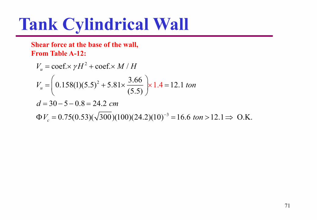
Tank Cylindrical WallShear force at the base of the wall,
From Table A-12:
71
2
2
3
coef. coef. /
3.660.158(1)(5.5) 5.81 12.1
(5.5)
30 5 0.8 24.2
0.75(0.53)( 300)(100)(24.2)(10) 16.6 12.1 O.
1.4
K.
u
u
c
V H M H
V ton
d cm
V ton

Tank Cylindrical WallDesign of Wall Reinforcement:
Ring Tension Reinforcement
72
240.34 100010.7 /
0.9(4200)
us
y
TA cm m
f
Or 5.35 cm2 on each side
Use 5 12 mm/m on each side.
Bending Reinforcement:
Inside Reinforcement (Mu=-13 t.m)
5
min2
2
0.85(300) 2.61(10) (11.9)1 1 0.0062
4200 100(24.2) (300)
0.0062 100 24.2 15 /sA cm m
Use 10 14 mm/m on the inside of the wall.
This reinforcement can be reduced half of shrinkage reinforcement at 0.5H
Tank Cylindrical Wall
73
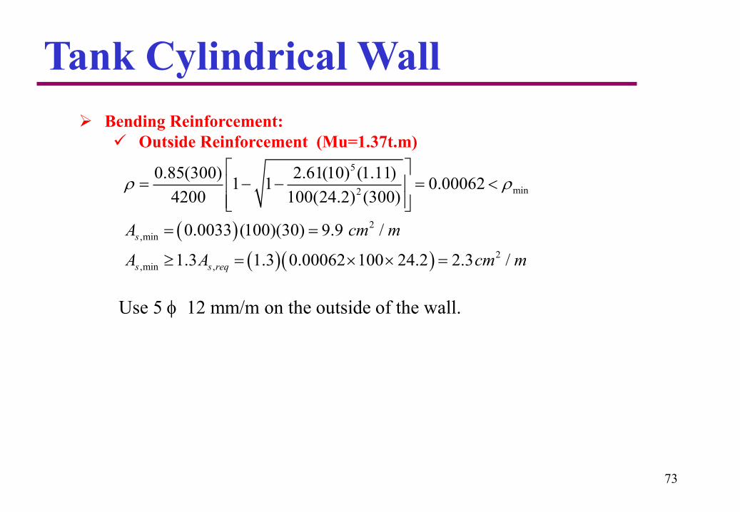
Bending Reinforcement:
Outside Reinforcement (Mu=1.37t.m)
Use 5 12 mm/m on the outside of the wall.
5
min2
2
,min
2
,min ,
0.85(300) 2.61(10) (1.11)1 1 0.00062
4200 100(24.2) (300)
0.0033 (100)(30) 9.9 /
1.3 1.3 0.00062 100 24.2 2.3 /
s
s s req
A cm m
A A cm m

Tank Base Slab
Radial Bending Moment in base SlabFrom Table A-17 T=Coef.*pR2= Coef. *(6.375)(5) 2 (2.3) t/m = 366.6 × Coef.
From Table A-19 T=Coef.*M = Coef. *(2.1) (2.3) t/m = 4.83 × Coef. t.m/m
Point Mr Coef.
Table A-17
Mr due to
water
pressure
Mr Coef.
Table A-19
Mr due to
distributed
M
Total
radial
Moment
(t.m/m)
Radial
moment per
Segment
(1m external)
0.15 R -0.1089 -39.92 -1.594 -7.70 -47.62 -7.14
0.20 R -0.0521 -19.10 -0.93 -4.49 -23.59 -4.72
0.25 R -0.02 -7.33 -0.545 -2.63 -9.96 -2.49
0.30 R 0.0002 0.07 -0.28 -1.35 -1.28 -0.38
0.40 R 0.022 8.07 0.078 0.38 8.44 3.38
0.50 R 0.0293 10.74 0.323 1.56 12.30 6.15
0.60 R 0.0269 9.86 0.51 2.46 12.32 7.39
0.70 R 0.0169 6.20 0.663 3.20 9.40 6.58
0.80 R 0.0006 0.22 0.79 3.82 4.04 3.23
0.90 R -0.0216 -7.92 0.90 4.35 -3.57 -3.21
1.0 R -0.049 -17.96 1.00 4.83 -13.13 -13.13
74
1.50.15
10
c
D
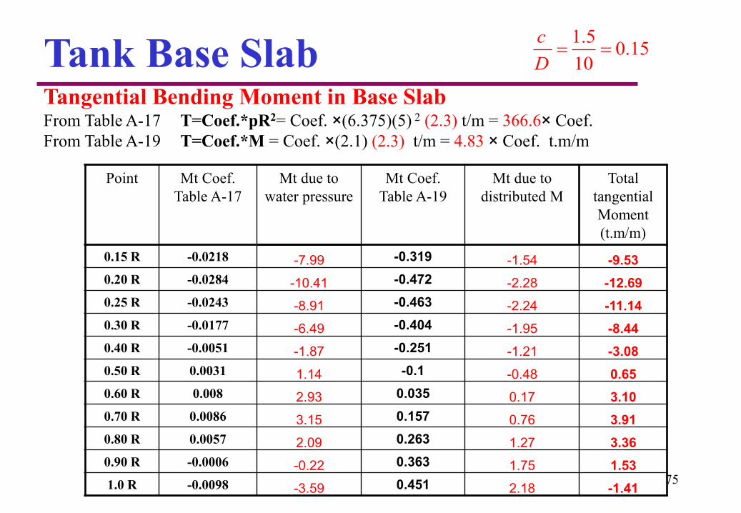
Tank Base SlabTangential Bending Moment in Base SlabFrom Table A-17 T=Coef.*pR2= Coef. ×(6.375)(5) 2 (2.3) t/m = 366.6× Coef.
From Table A-19 T=Coef.*M = Coef. ×(2.1) (2.3) t/m = 4.83 × Coef. t.m/m
Point Mt Coef.
Table A-17
Mt due to
water pressure
Mt Coef.
Table A-19
Mt due to
distributed M
Total
tangential
Moment
(t.m/m)
0.15 R -0.0218 -7.99 -0.319 -1.54 -9.53
0.20 R -0.0284 -10.41 -0.472 -2.28 -12.69
0.25 R -0.0243 -8.91 -0.463 -2.24 -11.14
0.30 R -0.0177 -6.49 -0.404 -1.95 -8.44
0.40 R -0.0051 -1.87 -0.251 -1.21 -3.08
0.50 R 0.0031 1.14 -0.1 -0.48 0.65
0.60 R 0.008 2.93 0.035 0.17 3.10
0.70 R 0.0086 3.15 0.157 0.76 3.91
0.80 R 0.0057 2.09 0.263 1.27 3.36
0.90 R -0.0006 -0.22 0.363 1.75 1.53
1.0 R -0.0098 -3.59 0.451 2.18 -1.4175
1.50.15
10
c
D

Tank Base Slab
76
2
2
. .
1.007(6.375)(5) 9.29 2.1 21.4 52 u
P coef pR coef M
P ton
Column’s LoadFrom Table A-13, load on center support of circular slab is:
2 2
3
35 5 0.9 29.1
( 6.375)(3.14)(5 0.291/ 2) 252 408.8
Length of shear section ( ) 3.14((10 0.291) 100)
1.4
3048
1.06 0.75( 300)(3048)(29.1)(10) 1221 408.8 O.K.
u
c
d cm
V P R column load ton
D d cm
V ton
Shear Strength of Base Slab:
a) At edge of wall:
`
0
`
0
0
`
0
20.53 1
0.27 2
1.06
c
sc c
c
f b d
dV f b d
b
f b d

Tank Base Slab
77
Shear Strength of Base Slab:
b) At edge of column capital:
Radius of critical section = 75 + d/2 = 75 + (50 - 5.0 - 0.9)/2 = 97.05 cm
2 2
3
50 5 0.9 44.1
( 6.375)(3.14)(0.9705) 252 225.6
1.06 0.75( 300)(2
1.4
97.05)(44.1)(10) 392.8 225.6 O.K.
u
c
d cm
V P R column load ton
V ton
Tank Base Slab
78
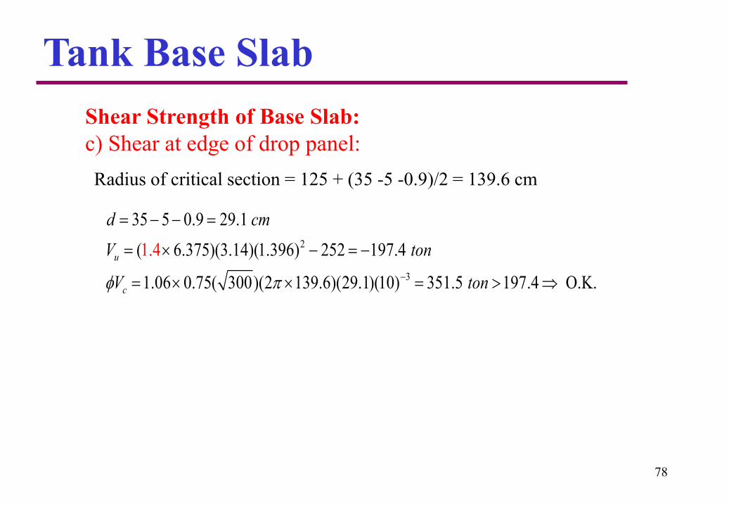
Shear Strength of Base Slab:
c) Shear at edge of drop panel:
2
3
35 5 0.9 29.1
( 6.375)(3.14)(1.396) 252 197.4
1.06 0.75( 300)(2 139.6)(29.1)(10) 351.5 197.4 O.
1
K
.4
.
u
c
d cm
V ton
V ton
Radius of critical section = 125 + (35 -5 -0.9)/2 = 139.6 cm

Tank Base Slab
79
Slab Reinforcement
a) Tangential Moments
2
,mi
5
m2
m
n
in
in
For
0.003 (1
12.69 t.m/m at 0.2 R
0.85(300) 2.61(10) (12.69)1 1 0.0017
4200 100(44.1) (300)
You can simply use 0.0018 to be used for each lay
00)(50) 15.0 /
er (Top&Bottom)
t
sA cm m
A
M
2
,min
Use 12 mm @ 12.5 cm (8 12 / m) Top ring reinf .
12 mm @ 12.5 cm (8
0.0018 (100)(5
12 / m) Bott
0) 9
om ring rein
f
/
.
s cm m

Tank Base Slab
80
Slab Reinforcement
a) Tangential Moments
2
,m
5
min2
in
For 3.91 t.m/m at 0.7 R
35 5 0.9 29.1
0.85(300) 2.61(10) (3.91)1 1 0.0012
4200 100(29.1)
0.003( )(100)(35) 5.25 /
2
Use 10 mm @ 12.5 cm Bottom ring re
(3
f
00)
in .
t
sA
M
d c
cm m
m

Tank Base Slab
81
Slab Reinforcement
a) Tangential Moments
5
min2
2
,min
1.41 t.m/m at inside face of wall
35 5 0.9 29.1
0.85(300) 2.61(10) (1.41)1 1 0.00044
4200 100(29.1) (300)
0.003( )(100)(35) 5.25 /
2
Use 10 mm @ 12.5
For
cm top and bottom r
t
s
M
d cm
A cm m
ing reinf .

Tank Base Slab
82
Slab Reinforcement
b) Radial Moments
5
min2
2
13.13 . /
35 5 0.9 29.1
0.85(300) 2.61(10) (13.13)1 1 0.00424
4200 1
At inside
00(29.1) (300)
(0.00424)(100)(29.1) 12.35 /
Use 14 mm @
face of the wall
12.5 cm
2
u
s
s
M t m m
d cm
A cm m
A total
2(5.0)(12.35) 387.8 cm

Tank Base Slab
83
Slab Reinforcement
b) Radial Moments
5
min2
2
2
12.32 . / at 0.6 R
35 5 0.9 29.1
0.85(300) 2.61(10) (12.32)1 1 0.004
4200 100(29.1) (300)
(0.004)(100)(2
At max. ve mom
9.1) 11.6 /
2 (0.6 5.0)(
ent
11.6) 218 5
.
u
s
s
M t m m
d cm
A cm m
A total cm
Tank Base Slab
84
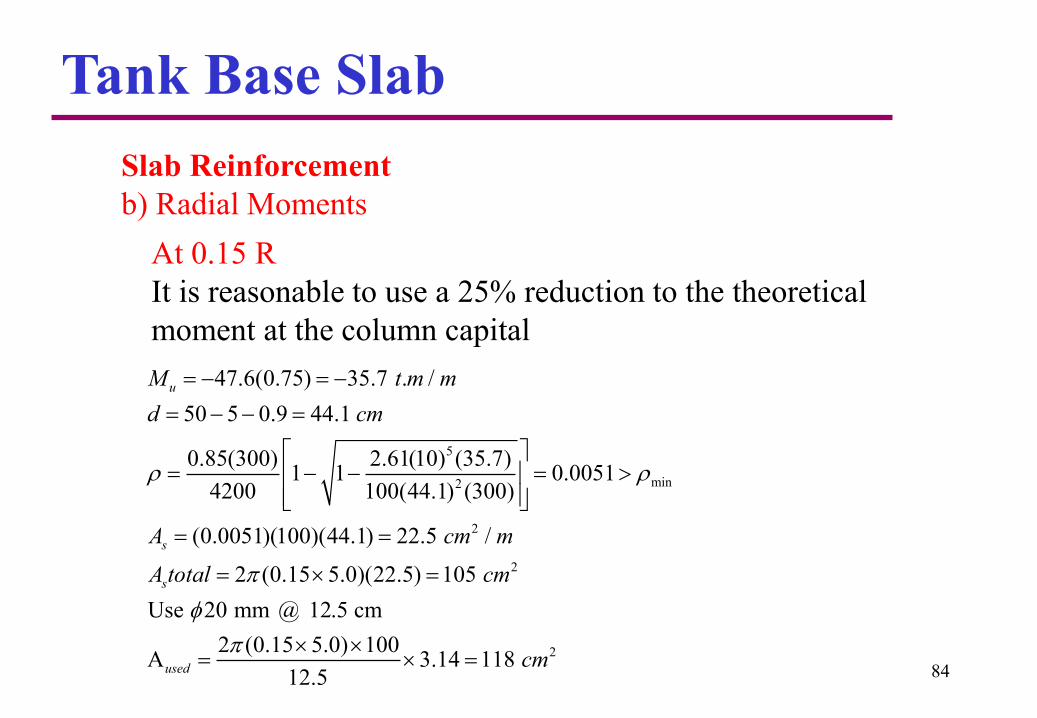
Slab Reinforcement
b) Radial Moments
At 0.15 R
It is reasonable to use a 25% reduction to the theoretical
moment at the column capital
5
min2
2
2
47.6(0.75) 35.7 . /
50 5 0.9 44.1
0.85(300) 2.61(10) (35.7)1 1 0.0051
4200 100(44.1) (300)
(0.0051)(100)(44.1) 22.5 /
2 (0.15 5.0)(22.5) 105
Use 20 mm @ 12.5 cm
u
s
s
M t m m
d cm
A cm m
A total cm
22 (0.15 5.0) 100A 3.14 118
12.5used cm

Tank Base Slab
85
Slab Reinforcement
b) Radial Moments
5
min2
2
2
23.6 . /
50 5 0.9 44.1
0.85(300) 2.61(10) (23.6)1 1 0.0033
4200 100(44.1) (300)
(0.0033)(100)(44.1) 14.5 /
2 (0.2 5.0)(14.5) 91.1
At 0.2 R
u
s
s
M t m m
d cm
A cm m
A total cm

Tank Base Slab
86
Slab Reinforcement
b) Radial Moments
5
min2
2
2
1.3 . /
35 5 0.9 29.1
0.85(300) 2.61(10) (1.3)1 1 0.0004
4200 100(29.1) (300)
(0.003)(100)(35) 10.5 /
2 (0.3 5.0)(10.5) 99
At 0.3 R
u
s
s
M t m m
d cm
A cm m
A total cm
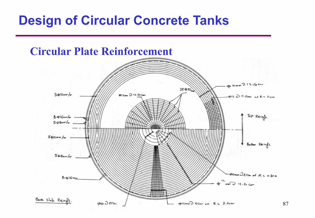
Design of Circular Concrete Tanks
Circular Plate Reinforcement
87
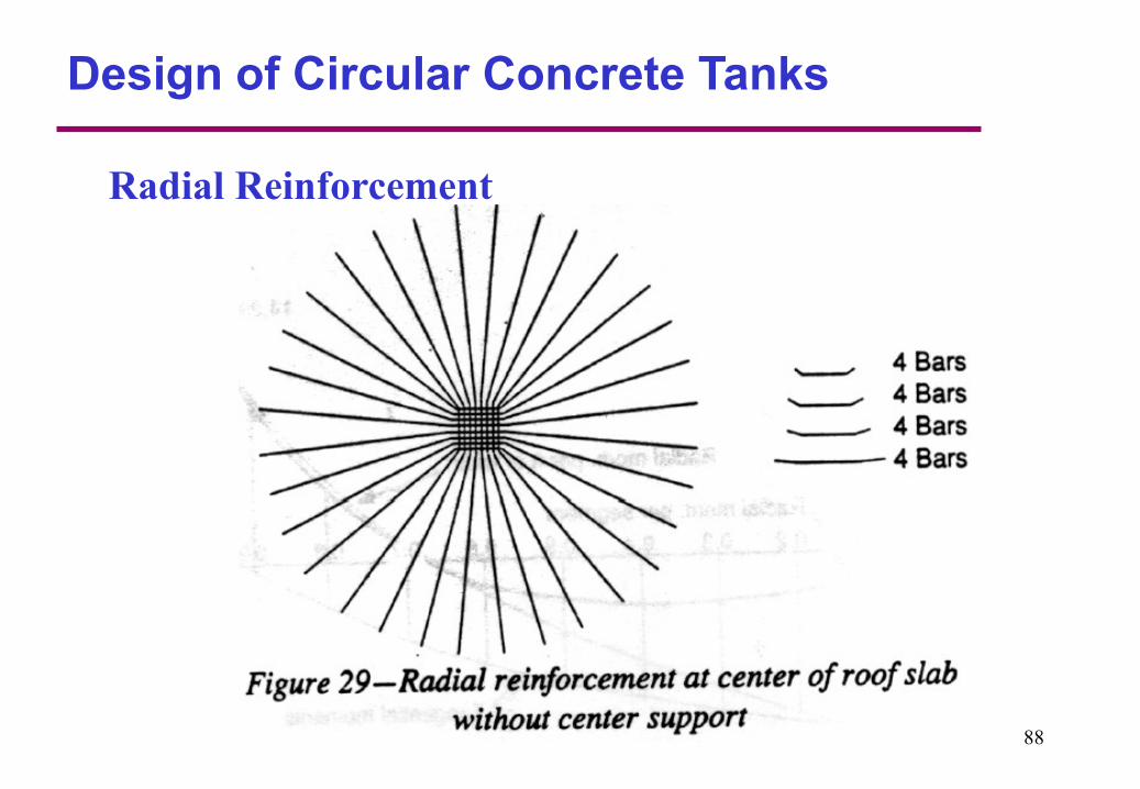
Design of Circular Concrete Tanks
Radial Reinforcement
88
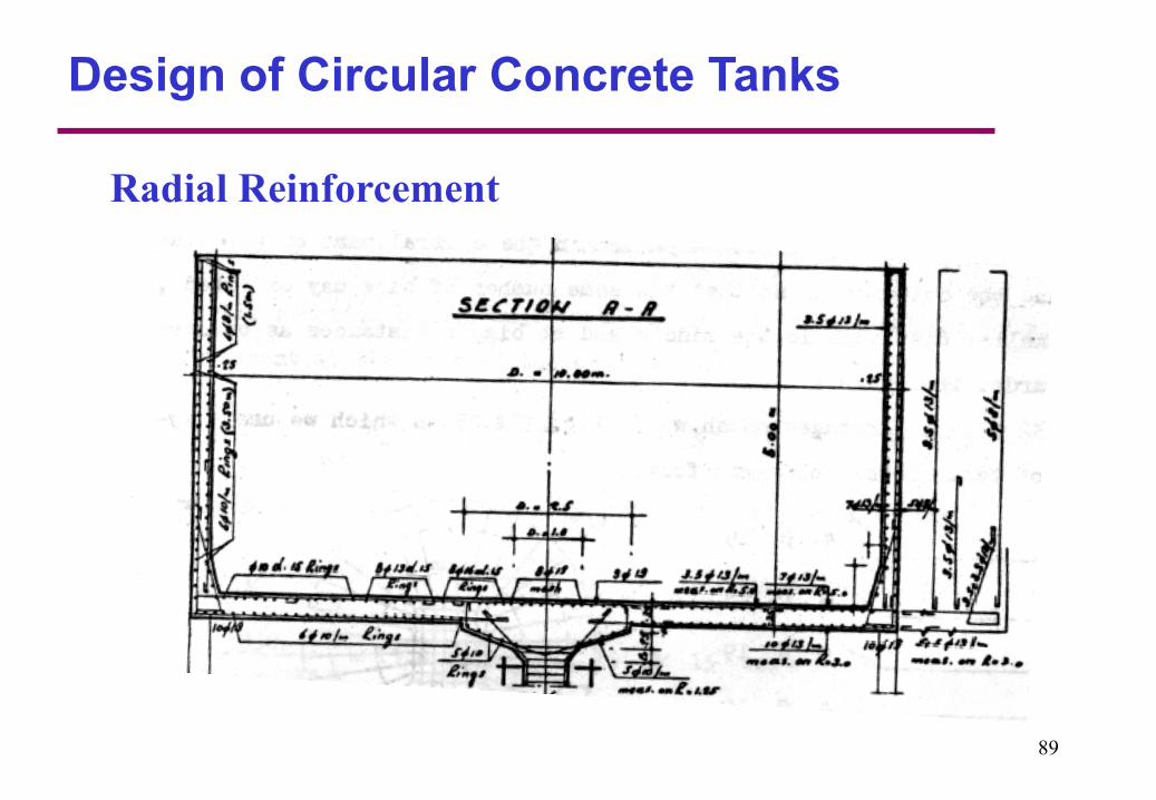
Design of Circular Concrete Tanks
Radial Reinforcement
89

90
Home Work #1
Project # 1
Design Anaerobic Sludge Digester for the Gaza
central sewage project with diameter
D=27.5 m and Height H=25.0 m
1. Calculation Sheet with assumptions.
2. All Structural, reinforcement and water
stop details drawings
3. Bill of Quantities