
DESIGN OF BROADBAND CIRCULARLY POLARIZED …ww.jpier.org/PIER/pier120/30.11070106.pdf · DESIGN OF...
21
Progress In Electromagnetics Research, Vol. 120, 513–533, 2011 DESIGN OF BROADBAND CIRCULARLY POLARIZED SQUARE SLOT ANTENNA WITH A COMPACT SIZE J.-Y. Sze * and S.-P. Pan Department of Electrical and Electronic Engineering, Chung Cheng Institute of Technology, National Defense University, 190 Sanyuan 1st. St., Dasi Township, Taoyuan County 33508, Taiwan, R.O.C. Abstract—This paper proposes a newly designed compact coplanar- waveguide-fed wideband circularly polarized (CP) printed square slot antenna (PSSA), in the square slot of which are a halberd-shaped feeding signal line and a square ring patch. By placing a specially designed metal reflector behind the bidirectional CP PSSA, one can obtain unidirectional CP patterns with a associated 3-dB axial-ratio bandwidth (ARBW) almost the same as that of the bidirectional antenna. The bidirectional L- and S -band PSSAs designed on FR4 substrates have 3-dB ARBWs as large as 25.3% and 29.1%, respectively. For the L-band antennas, the unidirectional design yields a 3-dB ARBW of 25.7% and a gain of about 3 dB higher than that of the bidirectional counterpart. In all these 3-dB axial- ratio bands, impedance matching with VSWR ≤ 2 is also achieved. Most importantly, the design concepts, procedures, and rules for the proposed antenna are presented in detail. 1. INTRODUCTION With booming wireless-communication technologies, many satellite systems for global-navigation applications or communication applica- tions [1,2] have been made commercially available. To simultaneously support several satellite systems whose operating bands are closely spaced, large 3-dB axial-ratio bandwidths (ARBWs) are required for the antennas to be devised. Many popular circularly polarized (CP) patch antennas [3–7] and loop antennas [8,9] have narrower CP band- widths of less than 20%. Known not only for their compactness and low-profile features but also for their easily attained large CP band- widths using simple design technologies and constructions, printed slot Received 1 July 2011, Accepted 26 September 2011, Scheduled 11 October 2011 * Corresponding author: Jia-Yi Sze ([email protected]).
Transcript of DESIGN OF BROADBAND CIRCULARLY POLARIZED …ww.jpier.org/PIER/pier120/30.11070106.pdf · DESIGN OF...

Progress In Electromagnetics Research, Vol. 120, 513–533, 2011
DESIGN OF BROADBAND CIRCULARLY POLARIZEDSQUARE SLOT ANTENNA WITH A COMPACT SIZE
J.-Y. Sze* and S.-P. Pan
Department of Electrical and Electronic Engineering, Chung ChengInstitute of Technology, National Defense University, 190 Sanyuan 1st.St., Dasi Township, Taoyuan County 33508, Taiwan, R.O.C.
Abstract—This paper proposes a newly designed compact coplanar-waveguide-fed wideband circularly polarized (CP) printed square slotantenna (PSSA), in the square slot of which are a halberd-shapedfeeding signal line and a square ring patch. By placing a speciallydesigned metal reflector behind the bidirectional CP PSSA, one canobtain unidirectional CP patterns with a associated 3-dB axial-ratiobandwidth (ARBW) almost the same as that of the bidirectionalantenna. The bidirectional L- and S -band PSSAs designed onFR4 substrates have 3-dB ARBWs as large as 25.3% and 29.1%,respectively. For the L-band antennas, the unidirectional designyields a 3-dB ARBW of 25.7% and a gain of about 3 dB higherthan that of the bidirectional counterpart. In all these 3-dB axial-ratio bands, impedance matching with VSWR ≤ 2 is also achieved.Most importantly, the design concepts, procedures, and rules for theproposed antenna are presented in detail.
1. INTRODUCTION
With booming wireless-communication technologies, many satellitesystems for global-navigation applications or communication applica-tions [1, 2] have been made commercially available. To simultaneouslysupport several satellite systems whose operating bands are closelyspaced, large 3-dB axial-ratio bandwidths (ARBWs) are required forthe antennas to be devised. Many popular circularly polarized (CP)patch antennas [3–7] and loop antennas [8, 9] have narrower CP band-widths of less than 20%. Known not only for their compactness andlow-profile features but also for their easily attained large CP band-widths using simple design technologies and constructions, printed slot
Received 1 July 2011, Accepted 26 September 2011, Scheduled 11 October 2011* Corresponding author: Jia-Yi Sze ([email protected]).

514 Sze and Pan
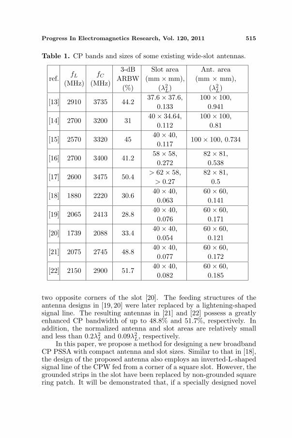
antennas have received much attention in recent years [10–22]. Amongthese antenna designs, the CP ring slot antennas in [10–12] still haveCP bandwidths of less than 25% even though many CP-bandwidth-enhancement efforts have been made. The remaining ones are regardedas wideband CP antennas, whose 3-dB ARBWs are all larger than 25%with respect to the center frequencies of their 3-dB axial-ratio (AR)bands (or alternatively called CP bands for short). For comparison,the 3-dB ARBWs and antenna sizes of these wideband antennas aresummarized in Table 1. In this table, fL is the lower-edge frequency ofthe CP band, and λL is the corresponding free-space wavelength. Theslot area (the antenna area) is the area of the smallest rectangle thatcan enclose the slot (the entire low-profile antenna). Note that theslot and antenna areas are measured in λL instead of the free-spacewavelength λ0 at the CP-band center frequency f0 because for twowideband CP antennas having the same fL but different f0, the onewith a wider CP band will have a larger electric size if λ0 is chosen asthe reference. Choosing λ0 as the reference will result in somewhat un-fair size comparison between the two wideband CP antennas. In fact,if λL is chosen as the reference instead, the wider-band CP antennawill be of the same size as that of the narrower-band CP antennas.
The simple antenna designs in [13–15] have a circular slot ora triangular slot fed by a closely coupled L-shaped microstrip line.Although the 3-dB ARBWs of these slot antennas are as large as31% to 45%, their normalized antenna areas are comparatively large(larger than 0.7λ2
L) and cannot be reduced if the 3-dB ARBWs areto be maintained because reducing the ground-plane size (and hencethe antenna area) would raise the lower-edge frequency of an antenna’sCP band, thus significantly shrinking the CP bands and shifting up theassociated CP-band center frequencies. In addition, their normalizedslot areas are larger than 0.1λ2
L. The antenna designs in [16, 17] withan L-shaped coupled feedline and embedded stub(s) in the slot regionshave smaller antenna areas than those in [13–15] while still having largeslot areas.
To overcome the drawbacks (i.e., large antenna or slot area, orboth) of the above slot antennas which are all fed by microstrip lines,many broadband CP slot antennas with new design strategies havebeen developed [18–22]. In particular, these antennas are all fed byco-planar waveguides (CPWs). The antenna design proposed in [18]employed an inverted-L-shaped signal line of the CPW fed from acorner of a square slot and an additional pair of grounded strips in theslot. The antenna designs proposed in [19, 20] are fed by a widenedsignal line of the CPW. Two grounded inverted-L metallic strips [19] ortwo grounded square patches with E-shaped slits [20] are placed around
Progress In Electromagnetics Research, Vol. 120, 2011 515
Table 1. CP bands and sizes of some existing wide-slot antennas.
ref.fL
(MHz)fC
(MHz)
3-dBARBW
(%)
Slot area(mm×mm),
(λ2L)
Ant. area(mm × mm),
(λ2L)
[13] 2910 3735 44.237.6× 37.6,
0.133100× 100,
0.941
[14] 2700 3200 3140× 34.64,
0.112100× 100,
0.81
[15] 2570 3320 4540× 40,0.117
100× 100, 0.734
[16] 2700 3400 41.258× 58,0.272
82× 81,0.538
[17] 2600 3475 50.4> 62× 58,
> 0.2782× 81,
0.5
[18] 1880 2220 30.640× 40,0.063
60× 60,0.141
[19] 2065 2413 28.840× 40,0.076
60× 60,0.171
[20] 1739 2088 33.440× 40,0.054
60× 60,0.121
[21] 2075 2745 48.840× 40,0.077
60× 60,0.172
[22] 2150 2900 51.740× 40,0.082
60× 60,0.185
two opposite corners of the slot [20]. The feeding structures of theantenna designs in [19, 20] were later replaced by a lightening-shapedsignal line. The resulting antennas in [21] and [22] possess a greatlyenhanced CP bandwidth of up to 48.8% and 51.7%, respectively. Inaddition, the normalized antenna and slot areas are relatively smalland less than 0.2λ2
L and 0.09λ2L, respectively.
In this paper, we propose a method for designing a new broadbandCP PSSA with compact antenna and slot sizes. Similar to that in [18],the design of the proposed antenna also employs an inverted-L-shapedsignal line of the CPW fed from a corner of a square slot. However, thegrounded strips in the slot have been replaced by non-grounded squarering patch. It will be demonstrated that, if a specially designed novel

516 Sze and Pan
metal reflector is placed behind, the new CP PSSA can be furtherdeveloped to suppress the backward radiation and hence to increasethe antenna gain. Most importantly, the design concepts, procedures,and rules for the proposed antenna will be systematically elucidatedin detail.
2. ANTENNA CONFIGURATION
Figure 1(a) shows the geometry of the proposed CP PSSA, whichis fabricated on a square microwave substrate with side length G,thickness h, dielectric constant εr, and loss tangent tan δ. A squareslot of side length Ls is symmetrically etched from the ground planeprinted on one side of the substrate. The antenna is fed from the lower-right corner of the square slot by a 50-Ω CPW with a wf -wide signalline and two g-wide gaps. The CP operation is mainly attributed totwo structures, one being a specially designed feeding structure andthe other a square ring patch implanted in the slot region. The feedingstructure consists of two w1-wide strip sections oriented in the x andy directions that are connected to the signal line of the corner-fedCPW and protruded into the square slot. The two strip sections areg-distance away from the left, right, and lower edges of the square slot.For convenience, refer to the strips that are protruded into the slotfrom the CPW feedline as a feeding signal line. The feeding signalline of the proposed antenna (see Fig. 1(a)) is then of halberd shape.This halberd-shaped feeding signal line will be seen later to accountfor the CP operation in the high-frequency portion of the designedCP band. On the other hand, the CP operation in the low-frequency
x
yz
H
GL
(b)
2
G
L s
wf
w1
g
p
wp
x
y
g
Ground
h
(a)
w1
(c)
wr
H
G L
1
Figure 1. (a) Configuration of the proposed bidirectional CP slotantenna. (b) Configuration of the proposed unidirectional CP slotantenna. (c) Antenna reflector with side walls.
Progress In Electromagnetics Research, Vol. 120, 2011 517
portion is mainly governed by the square ring patch with width wp andouter side length `p. As shown in Fig. 1(a), the square ring patch issymmetrically implanted in the square slot region formed by the upperedge of the x-directed strip and the left edge (denoted by the dottedline in Fig. 1(a)) of the y-directed strip of the halberd-shaped feedingstructure and the left and upper edges of the Ls-wide square slot.
In addition, for the purpose of suppressing the backward radiationand hence increasing the antenna gain, a specially designed squaremetal reflector with side length GL (see Fig. 1(b)) is placed at adistance of roughly λ0/4 behind the substrate, where λ0 is the free-space wavelength at the center frequency of the CP band. This reflectoris designed to reflect the −z-directed wave due to the main radiatorinto the +z-directed wave so that this reflected wave possesses thesame polarization and phase as those of the +z directed radiation dueto the main radiator alone. Attached at the two ends of each side ofthe square reflector are vertical walls with width wr and height H.Note that the ground plane covering the substrate coincides with theplane containing the upper edges of the vertical walls.
3. CONCEPTS AND PROCEDURE OF ANTENNADESIGN
Note that most CP antennas in [13–22] are designed to operate inS band (2–4 GHz). For comparison with those antennas in termsof antenna gains and ARBWs, the antenna design procedures tobe developed in this study will also use an S-band CP PSSA asan example. Once established, these procedures will be verified bydesigning an additional L-band antenna. To systematically elucidatethe design methods and principles, we use a CPW-fed PSSA operatingat 2600 MHz as the reference antenna. For the ease of fabrication anddiscussion, all the antennas presented in this study adopt the samecommercially available FR4 substrates with εr = 4.4, tan δ = 0.019,and h = 1.6mm. The 50-Ω CPW then has the dimensions ofwf = 5 mm and g = 0.5 mm.
3.1. Slot Dimensions of CPW-fed CP PSSA
Because analytic formulas relating the dimensions and resonantfrequencies of a square slot etched from a finite ground plane are notavailable, we will first base on extensive simulations using Ansoft HFSSto determine an empirical formula relating the slot size of the referenceantenna to the fundamental-mode resonant frequency for certain ratiosof Ls to G. For a CPW-fed LP PSSA, its fundamental-mode resonant
518 Sze and Pan
frequency depends not only on the side length of the slot but also onthe ground-plane size. We found that with the ratio Ls/G in the rangeof 0.5–0.6, the resonant frequency and the side length of the slot areapproximately related by
fr ≈ c0
2(Ls + wf )√εeff ,1, εeff ,1 =
1 + εr
2(1)
where c0 is the speed of light in vacuum and εeff ,1 the effective dielectricconstant.
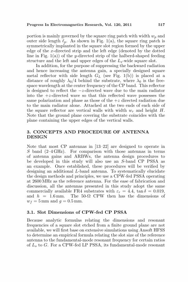
Next, in order to acquire a smaller size for the reference antennaoperating at 2600 MHz, we choose from the legitimate range for (1),the ratio Ls/G to be 0.6. This leads to Ls = 30mm and G = 50mmaccording to (1) with fr = 2600 MHz. The HFSS-simulated RL curvefor the reference antenna with the signal line of the CPW protrudedhalfway into the slot is shown in Fig. 2, which reveals that the resonantfrequency is 2538 MHz, quite close to the desired 2600 MHz. Note thatthe reference antenna is a linearly polarized (LP) one.
1.6 1.9 2.2 2.5 2.8 3.1 3.4 3.70
1
2
3
4
5
6
7
Axia
l R
ati
o (
dB
)
Frequency (GHz)
25
20
15
10
5
0
Type 2 ( p = 16.5 mm)
Type 2 ( p = 19.5 )
Type 2 ( p = 18.5)
Ref. Ant.
Ref. Ant.
Type 1
Ret
urn
Loss
(d
B)
VS WR = 2
(a)
(b)
Type 1 Type 2
Figure 2. Simulated (a) return loss and (b) axial ratio responses forthe reference antenna (linearly polarized), a type 1 antenna, and threetype 2 antennas with (`p = 16.5, 18.5, 19.5mm).

Progress In Electromagnetics Research, Vol. 120, 2011 519
3.2. Formation of CP Band at Higher Frequencies (Type 1Antenna)
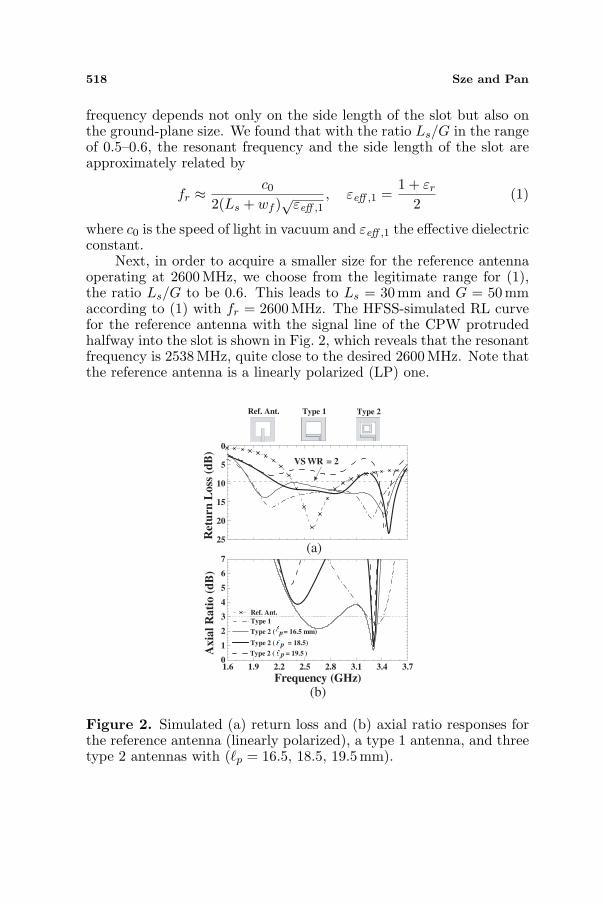
From the CP antennas proposed in [13–18], we notice that if the feedingsignal line of a PSSA is of L or inverted-L shape, CP radiation can beexcited in a certain frequency band. Our CP PSSA design starts withthis design concept. Let the protruded strip be a simple x directed linesection, which in conjunction with the signal line of the feeding CPWforms an inverted-L feeding signal line. Experience in CP antennadesign also suggests to us that various perturbation structures can beimplanted in the slot region to excite CP radiation in some differentfrequency bands. In order to reserve enough space for deployingperturbation structures, the CPW is arranged to asymmetrically feedthe square slot. This leads to a CPW-fed PSSA with an inverted-Lfeeding signal line, as denoted by the type 1 antenna shown in Fig. 2.Simulated RL and AR curves for the type 1 antenna with the x-directedfeeding strip section having a width of w1 = 5 mm and a length ofLs − 2g = 29 mm are shown in Fig. 2. Two resonant modes of thetype 1 antenna are found to resonate at 2120 and 3280 MHz. Theirassociated VSWR ≤ 2 impedance bands are combined into a singlewide impedance band of 1838–3484MHz. However, only the high-frequency resonant mode possesses CP characteristics. Note that thelowest AR of 2.5 dB occurs at 3324 MHz, which is denoted by fH0.Fig. 3 shows the HFSS-simulated magnetic current distributions of thetype 1 antenna at 3324 MHz for the four time instants of ωt = 0, 90,180, and 270. With the relatively weak magnetic currents neglectedfor clearness, plotted in these figures are only the major ones, which arefound to flow along the perimeter of the inverted-L feeding signal line.The predominant components of these major magnetic currents at ωt= 0, 90, 180, and 270 are found to be oriented along the x, y, −x,and −y directions, respectively. This implies the type 1 antenna in theCP band around fH0 produces RHCP radiation in the +z direction.Concluded from extensive simulations, we can empirically relate fH0
to the antenna dimensions by
fH0 ≈ c0
[2(Ls − 2g + wf ) + w1]√
εeff ,2, εeff ,2 =2εr
1 + εr. (2)
3.3. Formation of CP Band at Lower Frequencies (Type 2Antenna)
The low-frequency resonant mode (around 2120MHz) produces onlyLP radiation. To have a wide CP band for the designed antenna, we cantry to convert the LP radiation into CP radiation in the lower resonant
520 Sze and Pan
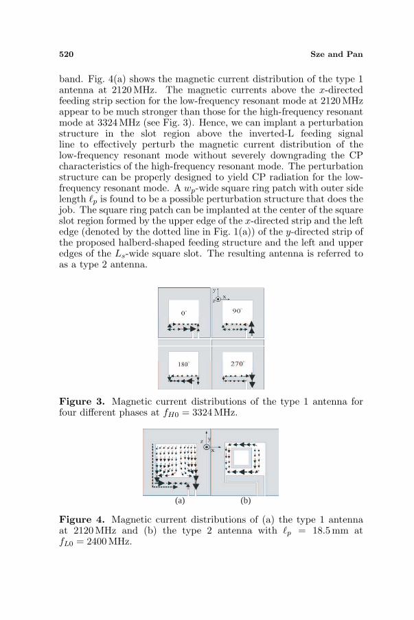
band. Fig. 4(a) shows the magnetic current distribution of the type 1antenna at 2120MHz. The magnetic currents above the x-directedfeeding strip section for the low-frequency resonant mode at 2120MHzappear to be much stronger than those for the high-frequency resonantmode at 3324MHz (see Fig. 3). Hence, we can implant a perturbationstructure in the slot region above the inverted-L feeding signalline to effectively perturb the magnetic current distribution of thelow-frequency resonant mode without severely downgrading the CPcharacteristics of the high-frequency resonant mode. The perturbationstructure can be properly designed to yield CP radiation for the low-frequency resonant mode. A wp-wide square ring patch with outer sidelength `p is found to be a possible perturbation structure that does thejob. The square ring patch can be implanted at the center of the squareslot region formed by the upper edge of the x-directed strip and the leftedge (denoted by the dotted line in Fig. 1(a)) of the y-directed strip ofthe proposed halberd-shaped feeding structure and the left and upperedges of the Ls-wide square slot. The resulting antenna is referred toas a type 2 antenna.
Figure 3. Magnetic current distributions of the type 1 antenna forfour different phases at fH0 = 3324 MHz.
(a) (b)
Figure 4. Magnetic current distributions of (a) the type 1 antennaat 2120 MHz and (b) the type 2 antenna with `p = 18.5mm atfL0 = 2400 MHz.
Progress In Electromagnetics Research, Vol. 120, 2011 521
Simulated RL and AR curves for three type 2 antennas with wp
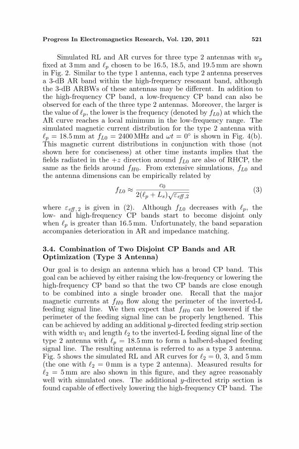
fixed at 3mm and `p chosen to be 16.5, 18.5, and 19.5mm are shownin Fig. 2. Similar to the type 1 antenna, each type 2 antenna preservesa 3-dB AR band within the high-frequency resonant band, althoughthe 3-dB ARBWs of these antennas may be different. In addition tothe high-frequency CP band, a low-frequency CP band can also beobserved for each of the three type 2 antennas. Moreover, the larger isthe value of `p, the lower is the frequency (denoted by fL0) at which theAR curve reaches a local minimum in the low-frequency range. Thesimulated magnetic current distribution for the type 2 antenna with`p = 18.5mm at fL0 = 2400MHz and ωt = 0 is shown in Fig. 4(b).This magnetic current distributions in conjunction with those (notshown here for conciseness) at other time instants implies that thefields radiated in the +z direction around fL0 are also of RHCP, thesame as the fields around fH0. From extensive simulations, fL0 andthe antenna dimensions can be empirically related by
fL0 ≈ c0
2(`p + Ls)√
εeff ,2(3)
where εeff , 2 is given in (2). Although fL0 decreases with `p, thelow- and high-frequency CP bands start to become disjoint onlywhen `p is greater than 16.5mm. Unfortunately, the band separationaccompanies deterioration in AR and impedance matching.
3.4. Combination of Two Disjoint CP Bands and AROptimization (Type 3 Antenna)
Our goal is to design an antenna which has a broad CP band. Thisgoal can be achieved by either raising the low-frequency or lowering thehigh-frequency CP band so that the two CP bands are close enoughto be combined into a single broader one. Recall that the majormagnetic currents at fH0 flow along the perimeter of the inverted-Lfeeding signal line. We then expect that fH0 can be lowered if theperimeter of the feeding signal line can be properly lengthened. Thiscan be achieved by adding an additional y-directed feeding strip sectionwith width w1 and length `2 to the inverted-L feeding signal line of thetype 2 antenna with `p = 18.5mm to form a halberd-shaped feedingsignal line. The resulting antenna is referred to as a type 3 antenna.Fig. 5 shows the simulated RL and AR curves for `2 = 0, 3, and 5 mm(the one with `2 = 0mm is a type 2 antenna). Measured results for`2 = 5 mm are also shown in this figure, and they agree reasonablywell with simulated ones. The additional y-directed strip section isfound capable of effectively lowering the high-frequency CP band. The

522 Sze and Pan
1.6 1.9 2.2 2.5 2.8 3.1 3.4 3.70
1
2
3
4
5
6
Type 2A
xia
l R
ati
o (
dB
)
Frequency (GHz)
50
40
30
20
10
0
2= 0 mm (sim.) (Type 2)
2= 3 (sim.)
2= 5 (sim.)
2= 5 (mea.) (Type 3)
Ret
urn
Lo
ss (
dB
)
(b)
(a)
VSWR = 2
Type 3
Figure 5. (a) Return loss and (b) axial ratio for three different valuesof `2 with G = 50mm, Ls = 30 mm, wf = 5 mm, g = 0.5mm,`1 = 24 mm, `p = 18.5mm.
empirical formula pertaining to fH0 can then be modified as
fH0 ≈ c0
[2(Ls − 2g + `2 + wf ) + w1]√
εeff ,2 (4)
Observe that the decrease of fH0 goes along with a slight increaseof fL0. This phenomenon can be explained by the fact that the regionallowing the magnetic current to flow around the square ring patch atfL0 (see Fig. 4(b)) is squeezed because of the presence of the y-directedstrip section in the halberd-shaped feeding signal line. The equivalentlyslightly shortened route of the magnetic current distribution thus leadsto a slightly increased fL0. In the meantime, with `2 = 5 mm chosenfor the type 3 antenna, the AR performance is greatly improved in thecombined broader CP band with a measured (simulated) minimum ARof 0.3 dB (0.09 dB) at 2705 MHz (2785 MHz). The measured 3-dB ARband of 2300–3020 MHz corresponds to a 3-dB ARBW of 27.1% withrespect to the center frequency 2660MHz. Note that the measuredCP-band center frequency of this type 3 antenna is very close to theimpedance-band center frequency of the reference antenna. Obviously,the characteristics of the proposed antenna design are to transformthe LP reference antenna in a broad band around the impedance-bandcenter frequency into a CP antenna. Because the +z-directed waves areboth RHCP in the two originally disjoint CP bands, the +z-directedwaves in the combined broader CP band are also RHCP.
Progress In Electromagnetics Research, Vol. 120, 2011 523
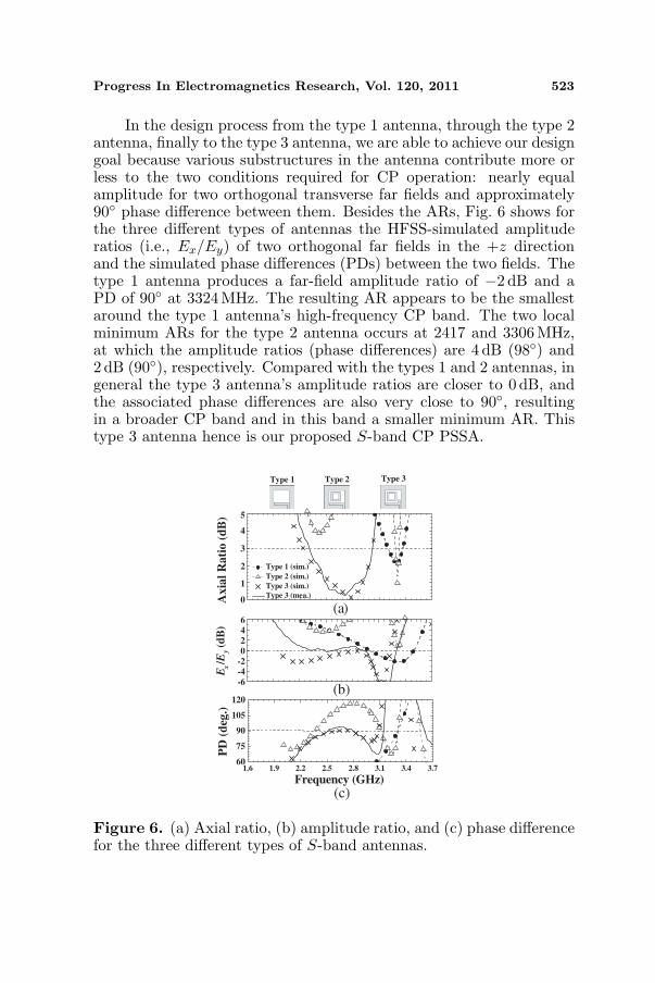
In the design process from the type 1 antenna, through the type 2antenna, finally to the type 3 antenna, we are able to achieve our designgoal because various substructures in the antenna contribute more orless to the two conditions required for CP operation: nearly equalamplitude for two orthogonal transverse far fields and approximately90 phase difference between them. Besides the ARs, Fig. 6 shows forthe three different types of antennas the HFSS-simulated amplituderatios (i.e., Ex/Ey) of two orthogonal far fields in the +z directionand the simulated phase differences (PDs) between the two fields. Thetype 1 antenna produces a far-field amplitude ratio of −2 dB and aPD of 90 at 3324MHz. The resulting AR appears to be the smallestaround the type 1 antenna’s high-frequency CP band. The two localminimum ARs for the type 2 antenna occurs at 2417 and 3306 MHz,at which the amplitude ratios (phase differences) are 4 dB (98) and2 dB (90), respectively. Compared with the types 1 and 2 antennas, ingeneral the type 3 antenna’s amplitude ratios are closer to 0 dB, andthe associated phase differences are also very close to 90, resultingin a broader CP band and in this band a smaller minimum AR. Thistype 3 antenna hence is our proposed S-band CP PSSA.
(a)
Type 1 (sim.)
Type 2 (sim.)
Type 3 (sim.)
Type 3 (mea.)
Ax
ial
Ra
tio
(d
B)
-6-4-20246
Ex/E
y (d
B)
(b)
1.6 1.9 2.2 2.5 2.8 3.1 3.4 3.60
75
90
105
120
7
Frequency (GHz)
(c)
PD
(d
eg.)
Type 3Type 1 Type 2
0
1
2
3
4
5
Figure 6. (a) Axial ratio, (b) amplitude ratio, and (c) phase differencefor the three different types of S-band antennas.

524 Sze and Pan
3.5. More Design Prototypes for Broadband S-band CPPSSAs
Note that `p is one of the parameters determining the location of thelow-frequency CP band. Hence, with the sizes of G and Ls fixed, weobserve that to a certain extent a larger `p gives a lower location of thelow-frequency CP band. If a larger `p is selected with `2 appropriatelyadjusted such that a combined broad CP band can still be obtainedaround a lower frequency location, antenna miniaturization can beachieved by controlling `p. That is, if G and Ls are fixed, we mayexplore whether the center frequency of the broad CP band can belowered by increasing `p; conversely, if the center frequency of thebroad CP band is preselected, we may check whether a smaller antennasize (i.e., smaller G and Ls) can be obtained by selecting a larger`p. In this subsection, four different CP PSSA prototypes with `p =16.5, 18.5, 19.5, and 20.5 mm are developed using the proposed designprocedures. Besides verifying the design procedures, the purpose is tofind to what extent the antenna can be miniaturized. Measured resultsfor these four antennas shown in Fig. 7 indicate that with `p in between0.7 (Ls−w1−g) and 0.8 (Ls−w1−g), a combined broad CP band canalways be obtained through adjusting `2. Among these four antennaprototypes, the one with `p = 19.5mm has the largest 3-dB ARBW of29.1% with respect to 2.52 GHz, the center frequency of the combinedCP band of 2155–2890 MHz. This CP band is completely enclosed bythe associated impedance band of 1714–2904 MHz (51.5%).
(b)
Ax
ial
Ra
tio
(d
B)
Frequency (GHz)
40
30
20
10
0
p = 16.5 mm , 2= 3
p= 18.5 , 2 = 5
p= 19.5 , 2 = 6
p= 20.5 , 2 = 7Ret
urn
Lo
ss (
dB
)
VSWR = 2
(a)
1.6 2.1 2.6 3.1 3.60
1
2
3
4
5
6
Figure 7. Measured (a) return loss and (b) axial ratio for four type 3antennas with different values of `p and the associated optimized `2.
Progress In Electromagnetics Research, Vol. 120, 2011 525
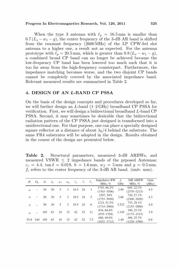
When the type 3 antenna with `p = 16.5 mm is smaller than0.7 (Ls −w1 − g), the center frequency of the 3-dB AR band is shiftedfrom the resonant frequency (2600 MHz) of the LP CPW-fed slotantenna to a higher one, a result not as expected. For the antennaprototype with `p = 20.5 mm, which is greater than 0.8 (Ls − w1 − g),a combined broad CP band can no longer be achieved because thelow-frequency CP band has been lowered too much such that it istoo far away from the high-frequency counterpart. Furthermore, theimpedance matching becomes worse, and the two disjoint CP bandscannot be completely covered by the associated impedance band.Relevant measured results are summarized in Table 2.
4. DESIGN OF AN L-BAND CP PSSA
On the basis of the design concepts and procedures developed so far,we will further design an L-band (1–2 GHz) broadband CP PSSA forverification. First, we will design a bidirectional broadband L-band CPPSSA. Second, it may sometimes be desirable that the bidirectionalradiation pattern of the CP PSSA just designed is transformed into aunidirectional one. For that purpose, one can place a specially designedsquare reflector at a distance of about λ0/4 behind the substrate. Thesame FR4 substrates will be adopted in the design. Results obtainedin the course of the design are presented below.
Table 2. Structural parameters, measured 3-dB ARBWs, andmeasured VSWR ≤ 2 impedance bands of the prposed Antennas;εr = 4.4, tan δ = 0.019, h = 1.6 mm, wf = 5 mm and g = 0.5mm.fc refers to the center frequency of the 3-dB AR band. (unit: mm).
H GL G Ls w1 wp p 1 2
Impedance BW
MHz, %
fc 3dB ARBW
MHz, %
Gain
(dBic) GHz
50 30 5 3 16.5 24 3 1743, 66.2%
(1763 3506) 2.89
645, 22.3%
(2570 3215)4.5
50 30 5 3 18.5 24 5 1297, 54%
(1753 3050) 2.66
720, 27.1%
(2300 3020)4.3
50 30 5 3 19.5 24 6 1214, 51.5%
(1714 2904) 2.522
735, 29.1%
(2155 2890)4.0
105 63 10 15 42 52 11834, 64.8%
(870 1704) 1.345
340, 25.3%
(1175 1515)3.9
55.8 140 105 63 10 15 42 52 7.5680, 49.6%
(1032 1712) 1.40
360, 25.7%
(1220 1580)6.8
−
−
−
−
−
−
−
−
−
−
−
−
−
−
∞
∞
∞
∞

526 Sze and Pan
4.1. Design of CP PSSA with Bidirectional Radiation
To verify the design procedures presented in Section 3, we will designan L-band CP PSSA with a purposely pre-determined CP-band centerfrequency of 1350MHz. This frequency is very close to half of theCP-band center frequency of 2660 MHz and to half of the minimum-AR frequency of 2705 MHz of a previously designed type 3 S-bandCP PSSA presented in Section 3.4. With fr = 1350 MHz, we haveLs ≈ 62.6 mm according to (1). For convenience, we round up the sizeto an integer value, i.e., Ls ≈ 63 mm. With Ls/G = 0.6 assumed, wehave G = 105mm, which is also of integer value. Other structuraldimensions in the design process are obtained as w1 = 10mm forthe type 1 antenna, `p = 42 mm and wp = 15mm for the type 2antenna, and `2 = 11 mm for the type 3 antenna. Measured RL andAR curves of these three antennas are shown in Fig. 8. As expected, thetype 3 antenna performs best. Its measured 3-dB AR band of 1175–1515MHz (25.3% with respect to the center frequency 1345 MHz) iscompletely enclosed by the associated VSWR ≤ 2 impedance band of870–1704MHz (64.8% with respect to the center frequency 1287MHz).Note that the CP-band center frequency is surprisingly close to thedesired one. Also shown in Fig. 8 are the simulated results of thetype 3 antenna, which agree well with the measured data. In addition,
Ax
ial
Ra
tio
(d
B)
Frequency (GHz)
40
30
20
10
0
VSWR = 2
Type 1 (mea.)
Type 2 (mea.)
Type 3 (mea.) (Ant.1)
Type 3 (sim.) (Ant.1)
Ret
urn
Lo
ss (
dB
)
(b)
(a)
Type 3Type 1 Type 2
0.80 1.05 1.30 1.55 1.80
8
7
6
5
4
3
2
1
0
Figure 8. (a) Return loss and (b) axial ratio for the three types ofL-band antennas designed using the procedures developed in Section 3.
Progress In Electromagnetics Research, Vol. 120, 2011 527
note that the evolution of the CP characteristics of the three L-bandantenna prototypes is rather similar to that for the three S-band ones.
4.2. Design of CP PSSA with Unidirectional Radiation
Antennas radiating into only one half-space are preferred for someapplications. In this subsection, we will add a reflector to the optimalL-band CP PSSA (i.e., the type 3 antenna) developed in Section 4.1in an attempt to acquire single broadside radiation. The radiation dueto the reflector-free CP PSSA is RHCP in the +z direction and LHCPin the −z direction. To suppress the backward (−z directed) radiationand hence to increase the antenna gain, the simplest way is to place aGL-wide square reflector at a distance of H = λ0/4 below the groundplane of the main radiator, where λ0 is the free-space wavelength at1345MHz. This leads to H = 55.8mm. Extensive simulations revealedthat the reflector somewhat degrades the CP performance. In general,the smaller is the value of GL, the smaller is the 3-dB ARBW. Aslong as GL is greater than 5λ0/8, a CP band with an AR of less than3 dB can still be obtained. However, if GL = 120mm (which is onlyslightly smaller than 5λ0/8) is selected, the minimum AR in the L banddegrades to 4 dB. In order not to increase the overall antenna size, wefixed GL at 140 mm (5λ0/8). We found that in this case the structuralparameter `2 can be adjusted again to improve the CP performance.However, the largest 3-dB ARBW that can be obtained is only 16.8%(1365–1615MHz) even with `2 adjusted to 7.5 mm. Simulated resultsof this antenna shown in Fig. 9 correspond to the case of wr = 0 mm.Such a greatly reduced 3-dB ARBW is roughly two-thirds of that ofthe reflector-free type 3 antenna presented in the previous subsection.
Nevertheless, the CP performance can still be improved withoutincreasing GL. If a vertical side wall is attached to each edge of thesquare reflector, the CP performance can be changed. Reflectors withside walls of many different heights have been simulated using AnsoftHFSS (the results are not shown here for conciseness). Among them,the side walls with a height of 55.8 mm (which is the same as H)were observed to result in the best CP performance. Hence, assumethat the height of the side walls is H for the rest of the discussion.Comparing the two sets of curves associated with wr = 0 and 70 mmshown in Fig. 9, the former corresponds to the case where there isno side wall at all, and the latter pertains to the case where theside walls completely surround the square reflector since in this casewr = GL/2 (see Fig. 1). The antenna with complete side walls has anorthogonal far-field amplitude ratio (Ex/Ey in the z direction) of 0 dBat 1272 MHz and a PD of 90 at 1310 MHz. The amplitude-ratio andPD curves are fast varying around these two frequencies, resulting in

528 Sze and Pan
(b)
Ax
ial
Rati
o (
dB
)
-5.0
-2.5
0.0
2.5
5.0
Ex/E
y(d
B)
(c)
1.10 1.25 1.40 1.55 1.7060708090
100110120130
(d)Frequency (GHz)
PD
(d
eg.)
454035302520151050
wr= 0 mm (sim.)
wr= 15 (sim.)
wr= 15 (mea.)
wr= 70 (sim.)
(a)
Ret
urn
Lo
ss (
dB
)
VSWR = 2
0
1
2
3
4
5
6
Figure 9. (a) Return loss, (b) axial ratio, (c) amplitude ratio, and(c) phase difference for the L-band antennas with different side walls.
a CP band of only 1245–1340 MHz. On the other hand, the antennawithout any side walls has an Ex/Ey ratio of −0.43 dB at 1563MHzand a PD of 90 at 1415MHz. Because the amplitude-ratio and PDcurves are relatively slowly varying in between these two frequencies,the resulting CP band (1365–1615 MHz) is relatively wide. Note thatthese two CP bands are disjoint but very close to each other. Onemay then expect that there exists a compromising reflector structurebetween the reflector with complete side walls and the one withoutany side walls such that the two CP conditions (Ex/Ey close to 0 dBand PD close to 90) can be obtained in both of the disjoint bands.From this design concept and through some simulations, we found thata reflector with partially covered side walls is indeed a compromisingreflector structure making the design goal achieved. With wr selectedto be 15 mm, which implies that two pieces of 15×55.8mm2 metals areattached at the two ends of each side of the square reflector (see Fig. 1),a broad 3-dB AR band of 1220–1580MHz (25.7% with respect to the
Progress In Electromagnetics Research, Vol. 120, 2011 529
center frequency 1400MHz) is obtained and completely covered by theimpedance band of 1032–1712 MHz (49.6%). The measurement agreeswell with the simulation. The measured CP-band center frequency(1400MHz) is slightly higher than that (1345MHz) of the reflector-free CP PSSA. The phenomenon that the CP-band center frequencyis slightly increased after the reflector is added can also be observedin [14]. Moreover, the 3-dB ARBW (25.3%) for the reflector-freeantenna is approximately the same as that (25.7%) of the one witha partial-side-wall reflector. Relevant measured data of these twoantennas are also summarized in the last two rows of Table 2.
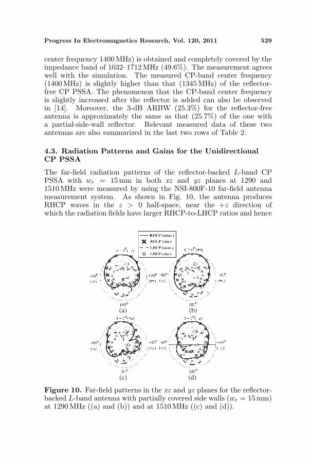
4.3. Radiation Patterns and Gains for the UnidirectionalCP PSSA
The far-field radiation patterns of the reflector-backed L-band CPPSSA with wr = 15 mm in both xz and yz planes at 1290 and1510MHz were measured by using the NSI-800F-10 far-field antennameasurement system. As shown in Fig. 10, the antenna producesRHCP waves in the z > 0 half-space, near the +z direction ofwhich the radiation fields have larger RHCP-to-LHCP ratios and hence
(a) (b)
(c) (d)
Figure 10. Far-field patterns in the xz and yz planes for the reflector-backed L-band antenna with partially covered side walls (wr = 15 mm)at 1290 MHz ((a) and (b)) and at 1510 MHz ((c) and (d)).

530 Sze and Pan
1.1 1.2 1.3 1.4 1.5 1.6 1.71234567
10
11
12
13
0
10
20
30
40
50
60
70
80
90
100
gain with reflector (meas.)
gain with reflector (sim.)
gain without reflector (meas.)
gain without reflector (sim.)
An
ten
na
Ga
in (
dB
ic)
Frequency (GHz)
with reflector (sim.)
without reflector (sim.)
Efficien
cy (%
)
Figure 11. Antenna gains in the +z direction and efficiencies forthe L-band reflector-free antenna (`2 = 11mm) and reflector-backedantenna (`2 = 7.5mm).
smaller ARs. The measurement agrees quite well with the simulation,especially for the RHCP waves in the z > 0 half-space. In themeasured data for both 1290 and 1510MHz, the forward (+z directed)RHCP wave is at least 19 dB larger than the backward (−z directed)RHCP wave and 8 dB larger than the backward LHCP wave. In the+z direction, the LHCP field is −26.5 dB (−30 dB) relative to theRHCP field at 1290MHz (1510MHz), corresponding to an AR of 0.9 dB(0.87 dB), which agrees with that shown in Fig. 9. Fig. 11 shows in the3-dB AR bands the measured and simulated antenna gains in the +zdirection and the simulated efficiencies for two L-band CP PSSAs, onewithout a reflector (`2 = 11 mm) and the other with a partial-side-wallreflector (`2 = 7.5mm and wr = 15 mm). The former antenna has lessgain than the latter by roughly 3 dB in the frequency range of interest,with a maximum gain of 3.9 dBic for the former and 6.8 dBic for thelatter. In addition, the simulated efficiencies for both antennas areabove 80% for most of the frequency range of interest.
5. CONCLUSIONS
Design procedures have been developed for designing a broadband CPPSSA by using an S-band antenna as an example. A similar processhas been applied to design an additional L-band CP PSSA to verifythe design procedures, which have been found easy to follow. Theoccupied normalized antenna (slot) area is 0.129λ2
L (0.046λ2L) for the
S-band antenna and 0.169λ2L (0.06λ2
L) for the reflector-less L-bandantenna. Both antennas possess a 3-dB ARBW of more than 25%with the corresponding 3-dB AR band completely enclosed in theassociated VSWR ≤ 2 impedance band. Finally, with a specially

Progress In Electromagnetics Research, Vol. 120, 2011 531
designed reflector placed behind the L-band antenna, the antenna gainsare increased by a factor of 3 dB. This antenna with unidirectionalradiation has a CP band of 1220–1580 MHz.
ACKNOWLEDGMENT
The authors would like to thank the reviewers for their careful reviewand valuable suggestions. This work was supported by the NationalScience Council of Taiwan, ROC, under Grand NSC 97-2221-E-606-024.
REFERENCES
1. Samper, J. M., R. B. Perez, and J. M. Lagunilla, GPS & Galileo:Dual RF Front-end Receiver And Design, Fabrication, and Test,McGraw-Hill, New York, 2009.
2. Johnson, R. C. and H. Jasik, Antenna Engineering Handbook,McGraw-Hill, New York, 1984.
3. Yang, S. S., K.-F. Lee, A. A. Kishk, and K.-M. Luk, “Designand study of wideband single feed circularly polarized microstripantennas,” Progress In Electromagnetics Research, Vol. 80, 45–61,2008.
4. Lai, C.-H., T.-R. Chen, and T.-Y. Han, “Circularly-polarizedreconfigurable microstrip antenna,” Journal of ElectromagneticWaves and Applications, Vol. 23, No. 2–3, 195–201, 2009.
5. Kasabegoudar, V. G. and K. J. Vinoy, “A broadband suspendedmicrostrip antenna for circular polarization,” Progress InElectromagnetics Research, Vol. 90, 353–368, 2009.
6. Lin, C., F.-S. Zhang, Y. Zhu, and F. Zhang, “A novel three-fedmicrostrip antenna for circular polarization application,” Journalof Electromagnetic Waves and Applications, Vol. 24, No. 11–12,1511–1520, 2010.
7. Chen, X., G. Fu, S.-X. Gong, Y.-L. Yan, and J. Chen, “Parametricstudies on the circularly polarized stacked annular-ring microstripantenna,” Progress In Electromagnetics Research C, Vol. 12, 65–77, 2010.
8. Tsai, C.-L., S.-M. Deng, C.-K. Yeh, and S.-S. Bor, “A novelshorted rectangular-loop antenna for circularly polarized waveoperations,” Journal of Electromagnetic Waves and Applications,Vol. 23, No. 10, 1323–1334, 2009.
9. Bai, X., X.-M. Zhang, L. Li, Q. Yang, and J. Li, “Double-sided printed four rhombic-loop antenna with parasitic loops

532 Sze and Pan
for circular polarization,” Journal of Electromagnetic Waves andApplications, Vol. 23, No. 13, 1795–1802 2009.
10. Sze, J. Y., C.-I. G. Hsu, M. H. Ho, Y. H. Ou, and M. T. Wu,“Design of circularly polarized annular-ring slot antennas fed bya double-bent microstripline,” IEEE Trans. Antennas Propagat.,Vol. 55, No. 11, 3134–3139, Nov. 2007.
11. Kumar, C. K. and S. N. Sinha, “A patch-loaded ring-slot antennafor wide band circular polarization,” Journal of ElectromagneticWaves and Applications, Vol. 23, Nos. 17–18, 2409–2419, 2009.
12. Deng, S.-M., C.-L. Tsai, M.-F Chang, and S.-S. Bor, “A studyon the non-uniform rectangular-ring slot antenna for broadbandcircular polarization operations,” Journal of ElectromagneticWaves and Applications, Vol. 24, No. 4, 543–555, 2010.
13. Tseng, L. Y. and T. Y. Han, “Microstrip-fed circular slot antennafor circular polarization,” Microwave Opt. Technol. Lett., Vol. 50,No. 4, 1056–1058, Apr. 2008.
14. Han, T. Y., Y. Y. Chu, L. Y. Tseng, and J. S. Row,“Unidirectional circularly-polarized slot antennas with broadbandoperation,” IEEE Trans. Antennas Proporgat., Vol. 56, 1777–1780, Jun. 2008.
15. Row, J. S. and S. W. Wu, “Circularly-polarized wide slot antennaloaded with a parasitic patch,” IEEE Trans. Antennas Propagat.,Vol. 56, 2826–2832, Sep. 2008.
16. Joseph, R., S. Nakao, and T. Fukusako, “Circular slot antennasusing L-shaped probe for broadband circular polarization,”Progress In Electromagnetics Research C, Vol. 18, 153–168, 2011.
17. Joseph, R. and T. Fukusako, “Bandwidth enhancement of circu-larly polarized square slot antenna,” Progress In ElectromagneticsResearch B, Vol. 29, 233–250, 2011.
18. Sze, J. Y., J. C. Wang, and C. C. Chang, “Axial-ratio bandwidthenhancement of asymmetric-CPW-fed circularly-polarised squareslot antenna,” IEE Elect. Lett., Vol. 44, No. 18, 1048–1049,Aug. 2008.
19. Sze, J. Y. and C. C. Chang, “Circularly polarized square slotantenna with a pair of inverted-L grounded strips,” IEEE Antennaand Wireless Propagat. Lett., Vol. 7, 149–151, 2008.
20. Chu, Q. X. and S. Du, “A CPW-fed broadband circularlypolarized square slot antenna,” Microwave Opt. Technol. Lett.,Vol. 52, 409–412, Feb. 2010.
21. Sze, J. Y., C. I. G. Hsu, Z. W. Chen, and C. C. Chang,“Broadband CPW-fed circularly polarized square slot antenna

Progress In Electromagnetics Research, Vol. 120, 2011 533
with lightening-shaped feedline and inverted-L grounded strips,”IEEE Trans. Antennas Propagat., Vol. 58, 973–977, Mar. 2010.
22. Liao, W. and Q.-X. Chu, “CPW-fed square slot antenna withlightening-shaped feedline for broadband circularly polarizedradiation,” Progress In Electromagnetics Research Letters, Vol. 18,61–69, 2010.