Design of beam shaping assembly (BSA) of D-D neutron ...
122
Ref. code: 25595622040748VXG Ref. code: 25595622040748VXG DESIGN OF BEAM SHAPING ASSEMBLY (BSA) OF D-D NEUTRON SOURCE FOR BORON NEUTRON CAPTURE THERAPY (BNCT) BY MUHARANI ASNAL A THESIS SUBMITTED IN PARTIAL FULFILLMENT OF THE REQUIREMENTS FOR THE DEGREE OF MASTER OF SCIENCE (ENGINEERING AND TECHNOLOGY) SIRINDHORN INTERNATIONAL INSTITUTE OF TECHNOLOGY THAMMASAT UNIVERSITY ACADEMIC YEAR 2016
Transcript of Design of beam shaping assembly (BSA) of D-D neutron ...

Ref. code: 25595622040748VXGRef. code: 25595622040748VXG
DESIGN OF BEAM SHAPING ASSEMBLY (BSA) OF D-D
NEUTRON SOURCE FOR BORON NEUTRON
CAPTURE THERAPY (BNCT)
BY
MUHARANI ASNAL
A THESIS SUBMITTED IN PARTIAL FULFILLMENT OF THE
REQUIREMENTS FOR THE DEGREE OF MASTER OF SCIENCE
(ENGINEERING AND TECHNOLOGY) SIRINDHORN
INTERNATIONAL INSTITUTE OF TECHNOLOGY
THAMMASAT UNIVERSITY
ACADEMIC YEAR 2016

Ref. code: 25595622040748VXGRef. code: 25595622040748VXG
i
DESIGN OF BEAM SHAPING ASSEMBLY (BSA) OF D-D NEUTRON
SOURCE FOR BORON NEUTRON CAPTURE THERAPY (BNCT)
A Thesis Presented
By
MUHARANI ASNAL
Submitted to
Sirindhorn International Institute of Technology
Thammasat University
In partial fulfillment of the requirements for the degree of
MASTER OF SCIENCE (ENGINEERING AND TECHNOLOGY)
Approved as to style and content by
Advisor and Chairperson of Thesis Committee
(Assoc. Prof. Dr. Alice Sharp)
Co-Advisor
(Assoc. Prof. Dr. Thawatchai Onjun)
Committee Member and Chairperson of Examination Committee
(Assoc. Prof. Dr. Pakorn Opaprakasit)
Committee Member
(Asst. Prof. Dr. Rattachat Mongkolnavin)
Committee Member
(Asst. Prof. Dr. Paiboon Sreearunothai)
Committee Member
(Dr. Thiansin Liamsuwan)
MAY 2017

Ref. code: 25595622040748VXGRef. code: 25595622040748VXG
ii
Acknowledgements
First and foremost, I thank my advisor, Dr. Thawatchai Onjun, for his
meticulous guidance and great patience towards the completion of my master degree.
He gives me independence in research and has been source of my learning. I am
thankful to the committee members, Dr. Alice Sharp, Dr. Thiansin Liamsuwan and
Dr. Rathachat Mongkolnavin, for giving valuable suggestions and comments. I also
acknowledge Sirindhorn International Institute of Technology of Thammasat
University for the master scholarship. Furthermore, I thank all the friends in PFRU
Lab for the stimulating discussions and for all the fun we have had in the last three
years.
Last but definitely does not means least, my deep thanks go to my family,
especially my husband Dr. Hanggara Sudrajat, for their love and support throughout
my journey in pursuing master degree.

Ref. code: 25595622040748VXGRef. code: 25595622040748VXG
iii
Abstract
DESIGN OF BEAM SHAPING ASSEMBLY (BSA) OF D-D NEUTRON SOURCE
FOR BORON NEUTRON CAPTURE THERAPY (BNCT)
by
MUHARANI ASNAL
Bachelor of Education (Physics), Universitas Riau, 2009
Master of Science (Physics), Universitas Gadjah Mada, 2011
Master of Science, Sirindhorn International Institute of Technology, Thammasat
University, 2017
Boron Neutron Capture Therapy (BNCT) has for many decades been promoted
as an innovative form of radiotherapy and has the potential to be the ideal form of
treatment for many types of cancers. To properly utilize BNCT method, neutrons
must have a specific properties, where can be achieved by treating with a particular
system, called a beam shaping assembly (BSA). By using appropriate geometry
configuration and material selection for BSA, the high quality of neutron beam can be
achieved. In this thesis, a BSA for modifying fast neutrons from D-D nuclear
reactions for BNCT was designed using the Monte Carlo simulation code Particle
Heavy and Ion Transport code System (PHITS). The proposed BSA consisted of 4 cm
of Pb as a multiplier, 16 cm of TiF3 as a first moderator, 60 cm of AlF3 as a second
moderator, 30 cm of Al2O3 as a reflector, and 3 cm of Li as a thermal filter. These
results are evaluated with the standard recommended by the International Atomic
Energy Agency (IAEA). The results showed that the proposed BSA was capable of
producing neutron flux with φepi/φfast of 27 and φepi/φthermal of 126, satisfying the IAEA
recommendation of neutron beams used for BNCT. It was also found that the
proposed BSA showed a better performance compared to the existing BSA designs in
terms of the epithermal neutron output quality without the need of fast neutron filters.

Ref. code: 25595622040748VXGRef. code: 25595622040748VXG
iv
Keywords: BNCT, BSA, D-D reaction, Monte Carlo simulation, epithermal neutron,
moderator.

Ref. code: 25595622040748VXGRef. code: 25595622040748VXG
v
Table of Contents
Chapter
1
2
Title Page
Signature Page…………………………………………………………..i
Acknowledgements ................................................................................ ii
Abstract .................................................................................................. iii
Table of Contents ................................................................................... v
List of Tables ........................................................................................ vii
List of Figures ...................................................................................... viii
Introduction ............................................................................................ 1
1.1 Overview .......................................................................................... 1
1.1.1. Cancer and human health ............................................................. 1
1.1.2. Boron Neutron Capture Therapy (BNCT) .................................... 2
1.1.2.1. The principles of BNCT ............................................................ 2
1.1.2.2. Neutron sources for BNCT ........................................................ 4
1.1.2.3. Boron compounds ...................................................................... 5
1.1.2.4. Beam Shaping Assembly (BSA) ............................................... 5
1.2. Motivation ....................................................................................... 6
1.3. Aims of the study ............................................................................. 7
1.4. Scope of the study ........................................................................... 7
Literature Review ................................................................................... 8
2.1 Clinical trials of BNCT for tumors ................................................... 8
2.2 BSA design to generate epithermal neutron based on D-T neutron
source for BNCT ............................................................................... 9
2.2.1 Introduction ................................................................................... 9
2.2.2 BSA Components ........................................................................ 10
2.2.2.1 Multiplier .................................................................................. 10
2.2.2.2 Moderator ................................................................................. 11
2.2.2.3 Fast and thermal neutron filter ................................................. 13
2.2.2.4 Reflector ................................................................................... 14
2.2.2.5 Collimator ................................................................................. 14
2.2.2.6 Gamma shielding ...................................................................... 15
2.2.3 BSA Models ................................................................................ 15

Ref. code: 25595622040748VXGRef. code: 25595622040748VXG
vi
3
4
5
Comparison of Existing Designs .......................................................... 18
3.1 Introduction .................................................................................... 18
3.2 Descriptive Of Code ....................................................................... 18
3.2 Results and Discussion ................................................................... 19
Development of BSA for BNCT .......................................................... 24
4.1 Introduction .................................................................................... 24
4.2. Materials and methods ................................................................... 24
4.3 Results and discussion .................................................................... 25
4.3.1 Optimization of BSA design........................................................ 25
4.3.2. Comparison of BSA designs ...................................................... 31
Conclusions and Recommendations ..................................................... 35
5.1 Conclusion ...................................................................................... 35
5.2 Recommendation and future work ................................................. 36
References ............................................................................................ 37
Appendices ........................................................................................... 40
Appendix A .......................................................................................... 40
Appendix B ........................................................................................... 70

Ref. code: 25595622040748VXGRef. code: 25595622040748VXG
vii
List of Tables
Tables Page
2.1
3.1
4.1
4.2
BNCT parameters of the three BSA configurations…………………… 17
BNCT in-air parameters of the three proposed BSA…………………... 22
BNCT free beam parameters recommended by the IAEA (IAEA, 2001) φ
represents neutron flux, n stands for neutron, and s stands for second… 25
BNCT free beam parameters of each BSA designs for D-D neutrons… 33

Ref. code: 25595622040748VXGRef. code: 25595622040748VXG
viii
List of Figures
Figures Page
1.1
1.2
2.1
2.2
2.3
3.1
3.2
3.3
4.1
4.2
4.3
4.4
4.5
4.6
4.7
4.8
Schematic illustration of neutron captures reaction in BNCT. ...................... 3
Comparison of in-depth thermal flux distributions for thermal and
epithermal neutrons. ....................................................................................... 4
The BSA model proposed by Rasouli and Masoudi. ................................... 15
The BSA model proposed by Rasouli et al... ............................................... 16
The BSA model proposed by Rahmani and Shahriari. ................................ 16
The BSA design (a) and neutron beam port flux per neutron source versus
energy (b) proposed by Eskandari and Kashian. ......................................... 20
The BSA design (a) and neutron beam port flux per neutron source versus
energy proposed (b) proposed by Rasouli and Masoudi. ............................. 20
The BSA design (a) and neutron beam port flux per neutron source versus
energy (b) proposed by Rasouli et al.. ......................................................... 21
Epithermal neutron flux per neutron source for different thicknesses of Pb
as the multiplier............................................................................................ 26
Epithermal neutron flux per neutron source for different thicknesses of TiF3
as the first moderator ................................................................................... 27
φepi/φfast for different thicknesses of AlF3 as the second moderator. ............ 28
φepi/φthermal (a) and φepi/φfast (b) for different thicknesses of Li as the thermal
neutron filter................................................................................................. 29
The proposed BSA design (a) and the neutron flux per neutron source at the
beam port exit versus neutron energy (b). ..................................................... 30
The BSA design A (a) and the neutron flux per neutron source at the beam
port exit versus energy (b). The BSA design was proposed by Eskandari and
Kashian. ........................................................................................................ 31
The BSA design B (a) and neutron flux per neutron source at the beam port
exit versus energy proposed (b). The BSA design was proposed by Rasouli
and Masoudi. ................................................................................................ 32
The BSA design C (a) and neutron flux per neutron source at beam port exit
versus energy (b). The BSA design was proposed by Rasouli et al. (2012). .. 33

Ref. code: 25595622040748VXGRef. code: 25595622040748VXG
1
Chapter 1
Introduction
1.1 Overview
1.1.1. Cancer and human health
Cancer is a group of abnormal cells that can uncontrollably increase their and
can invade other tissues. Glioblastoma (GBM) is a form of brain tumor and is
characterized by its rapid growth in the surrounding healthy tissue. It arises from
astrocytes, a supportive tissue of the brain (Parsons et al., 2008). GBM is extremely
malignant or cancerous. This is because the cells are supported by large network of
blood vessels and therefore are able to reproduce very quickly (Stupp et al., 2005).
The clinical history of a patient with GBM is typically short of less than 3 months in
more than 50% of patients. Common presenting symptoms are neurologic deficit such
as motor weakness, headache and increased intracranial pressure. Treatment for
preventing GBM is currently unavailable and there is no clear way to prevent it. The
commonly used methods for GBM therapy include surgery, chemotherapy, and
radiotherapy. GBM cannot be cured surgically and thus surgery merely attempts to
establish a pathologic diagnosis and to relieve any mass effect (Roa et al., 2004). The
addition of radiotherapy to surgery can increase the survival rate of patience
(Daumas‐Duport et al., 1988). The responsiveness of GBM to radiotherapy also
varies. Chemotherapeutic agents, targeted molecular agents, and antiangiogenic
agents may increase the therapeutic effect of radiotherapy (Mukundan et al., 2008).
In fact, such cancer treatments are proven ineffective. Therefore, developing
more appropriate techniques for this cancer is important and technological interesting.
The prerequisite for an ideal cancer therapy is capability of the proposed technique to
selectively destroy tumor cells without resulting in any damages to surrounding
normal cells. One of the promising methods for the GBM brain tumor is boron
neutron capture therapy (BNCT).

Ref. code: 25595622040748VXGRef. code: 25595622040748VXG
2
1.1.2. Boron Neutron Capture Therapy (BNCT)
BNCT is primarily targeted at tumors which are difficult to treat with
conventional therapy, such as GBM. BNCT was proposed in 1936 by Locher, a
scientist at the Franklin Institute in Pennsylvania, USA (Sweet, 1951). The first
clinical trials took place at Brookhaven National Laboratory in 1951 and
Massachusetts Institute of Technology in 1954 (Barth et al., 2005). Initial clinical
trials were unsuccessful due to normal tissue necrosis attributed to high
concentrations of boron in normal brain capillaries and the poor penetration depth of
thermal neutron beams. BNCT was resumed in Japan in 1968 using more selective
boron compounds (Nakagawa & Kageji, 2012). Results were encouraging although
they indicated that the survival times of these patients were no better than for those
receiving conventional radiotherapy.
1.1.2.1. The principles of BNCT
The rationale of using BNCT is based on the nuclear interaction of 10B, which is
loaded to tumor cells, with thermal neutrons (Figure 1.1). This nuclear interaction
generates high linear energy transfer (LET) α and 7Li particles through the boron
neutron capture reaction, 10B (n, α) 7Li (Eq. 1.1) (Yamamoto et al., 2013). The energy
of such heavy particles (2.34 MeV) can be locally deposited in the range of 5–9 µm,
which corresponds to the diameter of tumor cells. Therefore, high-LET irradiation of
tumor cells without unwanted damage to normal cells is expected.
10B + n → [11B]*→ α + 7Li + 2.34 MeV (1.1)

Ref. code: 25595622040748VXGRef. code: 25595622040748VXG
3
Figure 1. 1 Schematic illustration of neutron captures reaction in BNCT (Miyatake et
al., 2009). As seen, the cancer cells are selectively destroyed without damage for
adjacent normal cells.
Taking all of the above-mentioned features of BNCT into account, the critical
factors for successful therapy would be matching the neutron source with 10B-
containing agent, the amount of LET particles, and the selectivity of the 10B-
containing agent in tumor cells. Due to the fact that the location of GBM is typically
near the brain center surrounded by healthy tissues, tumor cells cannot be destroyed
by thermal neutrons. This is because the thermal neutrons penetrate weakly and thus
can stop in the skin or in other healthy tissues. The suitable neutrons for GBM therapy
are those having the energy in epithermal range of 1 eV–10 keV (Cerullo et al., 2004).
Ref. code: 25595622040748VXGRef. code: 25595622040748VXG
4
1.1.2.2. Neutron sources for BNCT
There are three basics sources of neutron beam: nuclear reactors, radioisotope
sources and particle accelerators (Barth et al., 1999). Nuclear reactors can provide
high level of neutron flux. However, nuclear reactors are complex and expensive.
Safety and practical features of particle accelerators triggered many researchers to
employ particle accelerators in hospitals as an example, neutron generators based on
D-T and D-D fusion reaction. Neutrons are emitted with energy of 2.45 MeV from D-
D and 14.1 MeV from D-T reactions (Mills, 1971).
Neutrons are divided in three classes according to their energy:
thermal (En < 0.5 eV)
epithermal (0.5 eV < En < 10 keV)
fast (En > 10 keV)
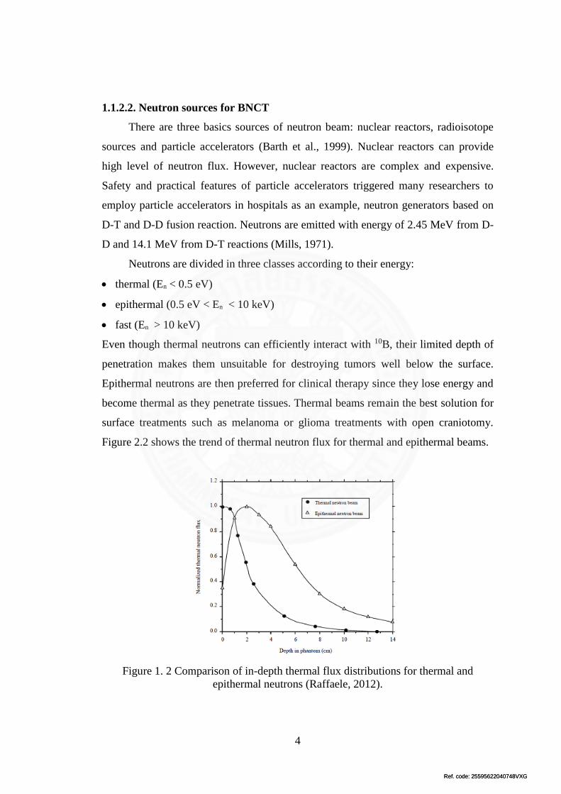
Even though thermal neutrons can efficiently interact with 10B, their limited depth of
penetration makes them unsuitable for destroying tumors well below the surface.
Epithermal neutrons are then preferred for clinical therapy since they lose energy and
become thermal as they penetrate tissues. Thermal beams remain the best solution for
surface treatments such as melanoma or glioma treatments with open craniotomy.
Figure 2.2 shows the trend of thermal neutron flux for thermal and epithermal beams.
Figure 1. 2 Comparison of in-depth thermal flux distributions for thermal and
epithermal neutrons (Raffaele, 2012).

Ref. code: 25595622040748VXGRef. code: 25595622040748VXG
5
General desirable beam properties can be summarized as follows:
Minimum beam intensity of 109 epithermal neutrons cm−2s−1. Lower intensities
often results in unacceptable longer irradiation times, while higher intensities
usually mean worse beam quality.
The fast neutron component should be kept as lower as possible.
The thermal component results in an additional damage to the scalp; the ratio of
thermal flux to epithermal flux should be around 0.05.
1.1.2.3. Boron compounds
In BNCT, dose targeting is achieved by selectively loading the stable isotope
10B into the malignant tissue via a tumor-selective boronated pharmaceutical infused
directly into the patient’s bloodstream. The biochemical selectively of the boronated
compound allows large concentrations of 10B to accumulate in the tumor cells relative
to normal tissue (3 to 4 times more), essentially differentiating normal and cancer
cells. The 10B compound alone is normally not toxic to cells. It is eliminated from the
body within a reasonable time frame after infusion.
1.1.2.4. Beam Shaping Assembly (BSA)
To ensure the applicability of neutrons generated by compact neuron sources,
i.e. a compact neutron sources based on D–D nuclear fusion reactions, a Beam
Shaping Assembly (BSA) must be required. This is because the radiation field
produced by compact neuron sources consists of some radiation dose components,
namely fast and thermal neutron doses and gamma dose. The clinical neutron beams
produced from BSA is allowed to include only minimal contaminants from the above-
mentioned dose components such that the background dose to healthy tissue is kept
within the tolerance limits. So, the main functions of BSA are to moderate the fast
neutrons produced by the nuclear fusion reactions to epithermal energy range and to
eliminate the formation of thermal neutrons (Rahmani & Shahriari, 2011). The main
characteristic of materials suitable for BSA is its effectiveness in reducing fast
neutron flux while enhancing epithermal flux. These kinds of materials thus allow for
efficient slowing down from the fast to the epithermal energies without removing

Ref. code: 25595622040748VXGRef. code: 25595622040748VXG
6
these epithermal neutrons. The net result would be an accumulation of epithermal
neutrons. Many studies have searched for optimal materials for accelerator-based
BNCT. Several materials which are proven to be good for BSA are Fluental and
Aluminum and Fluorin compounds. Fluental is a composite material consisting of a
mixture of AlF3 (69%), Al (30%), and LiF (1%). In fact, the most common moderator
materials in BSA for BNCT are Al and AlF3. They are used mainly due to their low
cost compared to Fluental. However, their low density compared to Fluental is one of
their main drawbacks. Overall, BSA is designed with appropriate choice of geometry
and materials to achieve sufficient beam intensity and suitable beam parameters.
1.2. Motivation
The geometry and materials used in each BSA design play a crucial role in
determining the characteristics of the resulting neutron beam. Therefore, it is needed
to carefully design the BSA so that the resulting neutron beam from compact neutron
reactors can be effectively applied for BNCT. Studies have been carried out to
investigate the suitability of BSA designs with compact D-D neutron sources for
BNCT (Durisi et al., 2007; Eskandari & Kashian, 2009; Fantidis et al., 2013; Rasouli
& Masoudi, 2012; Rasouli et al., 2012). The MCNP4B Monte Carlo code is usually
used for designing BSA. To give an instance, a BSA with a compact D–D neutron
generator was simulated using the MCNP4B Monte Carlo code (Fantidis et al., 2013).
The optimum moderator design is a conic part made of D2O followed by a TiF3 layer.
An epithermal neutron beam with appropriate quality can be achieved by using BiF3
as spectrum shifter and γ rays filter, Ti as fast neutron filter, and Li as thermal neutron
filter. Unfortunately, the obtained epithermal neutron flux (1.17 × 10⁶ n/cm2 s) cannot
satisfy the IAEA recommended values for clinical treatment.
Although the output neutron beam characteristics of existing BSA designs in
term of φepi/φfast and φepi/φthermal satisfy the IAEA criteria, their values are still
relatively low. Therefore, in this research, a beam shaping assembly with D-D and D-
T compact neutron generators is designed not only to fulfill the IAEA criteria but also
to feature appreciable values of φepi/φfast and φepi/φthermal.

Ref. code: 25595622040748VXGRef. code: 25595622040748VXG
7
1.3. Aims of the study
To design a beam shaping assembly (BSA) which is capable of producing an
epithermal neutron beam for BNCT based on neutrons from D-D reactions.
To compare the performance of the proposed BSA with some existing BSA
designs, i.e. by Eskandari and Kashian (Eskandari & Kashian, 2009), Rasouli et
al. (Rasouli et al., 2012), and Rasouli and Masoudi (Rasouli & Masoudi, 2012) in
term of the output neutron beam characteristics
1.4. Scope of the study
The neutron sources and BSA configuration are modeled with the particle heavy
and ion transport code (PHITS).
The simulated D-D neutron generators are assumed to produce fast neutrons with
the energy of 2.45 MeV.
The input fast neutron beam is assumed to possess a diameter of 1.7 cm with a
neutron flux of 1013 and 1015 n/s for D-D and D-T neutron generators,
respectively (Leung, 2009).
Optimum condition for producing epithermal neutrons is used together with the
IAEA standard of neutron beams for BNCT.

Ref. code: 25595622040748VXGRef. code: 25595622040748VXG
8
Chapter 2
Literature Review
2.1 Clinical trials of BNCT for tumors
The first BNCT trials were performed in the USA around 1960. Promising
results in the treatment of various cancers, especially head and neck cancer and
recurrent glioma, have been documented. The two boron compounds currently used in
BNCT are isodium mercaptoundecahydro-closo-dodecaborate (BSH) and
boronophenylalanine (BPA). BNCT is still being used in clinical trials and have
demonstrated some very good results.
Moreover, the development of linear accelerators specifically for BNCT
applications has also been progressed. All these facts lead to optimism to the future of
BNCT. Japan has the most pioneering treatment of patients with BNCT, while the
patient irradiations were mostly done in Finland. As an example, a 62-year-old man
patient with recurrent lung cancer in the previously irradiated chest wall was treated
with two-fractionated BNCT (Suzuki et al., 2012). BPA was used as a boron
compound in clinical trials of BNCT. Before irradiation, BPA was administered
intravenously at a rate of 200 mg/kg/h for 2.0 h in a BPA-fructose (BPA-f) solution.
During neutron irradiation, administration of BPA was continued at a rate of 100
mg/kg/h. The neutron beam for BNCT were produced from the Kyoto University
Reactor (KUR). Treatment planning and analysis of dose distributions is carried out
using the SERA system. At 51 and 52 months after initial radiotherapy, the two
fractions of BNCT were delivered with a one-month interval between them. In each of
the two BNCT sessions, irradiation was performed with epithermal neutron beams
with a 15 cm circular collimator and the same beam axis. Results showed that most of
the tumor regressed at seven months after the BNCT. No acute or late adverse events
were observed.

Ref. code: 25595622040748VXGRef. code: 25595622040748VXG
9
2.2 BSA design to generate epithermal neutron based on D-T neutron source for
BNCT
2.2.1 Introduction
Boron Neutron Capture Therapy (BNCT) is an indirect radiotherapy for
destruction of cancer cells. To utilize BCNT, 10B enriched compounds must be first
introduced into the patient’s body. The tissues are then irradiated by a low-energy
neutron beam, which can induce 10B(n,4He)7Li reactions producing secondary charged
particles with high biological effectiveness.
One of the critical parameters in BNCT is the neutron flux of a neutron source,
which must be in an appropriate rate for a sufficiently long enough time. The neutron
source providing the required neutron beam with high neutron flux has previously
seen only in a nuclear reactor. However, a suitable nuclear reactor for such purpose is
expensive and difficult to be realized in or near urban areas. This leads to the
development of other neutron sources for BNCT. For example, a compact neutron
generator based on the D-T fusion reaction was proposed as a suitable neutron source
for in-hospital treatments (Rasouli et al., 2012). It has greater safety, lower energy for
an incident deuteron beam, lower cost, smaller size, and higher social acceptability.
Owing to the fact that the typical neutron energy emitted from D-T fusion
reaction is 14.1 MeV, these neutrons cannot be used directly in BNCT. Therefore,
they are moderated to the epithermal energy range, between 1 eV and 10 keV. For this
purpose, neutrons must be treated within a particular system, called a beam shaping
assembly (BSA). By using appropriate geometry configuration and material selection
in BSA design, the quality and intensity of neutron beam can be optimized. Further,
as the intensity of the beam determines the treatment time, it must be considered in
the BSA design as well. According to the International Atomic Energy Agency
(IAEA) recommendation, epithermal neutron flux should be on the order of 109 n/cm2
s. It is pivotal to note that since the neutron flux usually decreases greatly when
neutrons pass through different components of BSA (Rasouli et al., 2012), it is
necessary to increase the number of neutrons emitted from the neutron source. In this
paper, the main components of BSA are compared and three BSA designs are
discussed.

Ref. code: 25595622040748VXGRef. code: 25595622040748VXG
10
2.2.2 BSA Components
As mentioned earlier, a BSA is basically designed to moderate high energy
neutrons to lower energies. In addition, it must remove fast and thermal neutrons and
gamma contaminations. A BSA consists of the multiplier, moderator, neutron filter,
reflector, gamma shielding and collimator as major components. In order to obtain a
suitable neutron beam for BNCT, a proper design must be employed.
2.2.2.1 Multiplier
A multiplier is used to increase the number of neutrons emitted from a neutron
source, due to the fact that the neutron flux is significantly decreased when neutrons
pass through different materials of the BSA. Hence, the material of the multiplier
should be properly chosen. Uranium is a typical material used as a neutron multiplier
to increase the number of neutrons via fission reactions.
Rasouli et al. used an isotropic source of 14.1 MeV neutrons placed at the
centre of a sphere made of natural uranium to determine the optimal thickness of
uranium, generating the highest flux of neutrons (Rasouli et al., 2012). The number of
neutrons per neutron source was found to increase with the uranium’s thickness and
reached a maximum value with a 14 cm radius. They also compared the geometry of
uranium, namely cylindrical and spherical. It was found that the uranium geometry
played a minor role on neutron multiplication. Two cylinders containing uranium at
the maximum point generate approximately the same number of neutrons as generated
by the spherical uranium. Thus, a sphere is certainly preferable due to its lightness.
Eskandari and Kashian, employed Pb and 238U as multiplier materials. The
large cross section of Pb for (n, 2n) reaction compensate for the neutron losses by
leakage and absorption during moderation (Eskandari & Kashian, 2009). Moreover,
the neutron flux was maximized by the use of 238U as a neutron multiplier. In this
design, Pb was modelled with 1, 2, 3, 4, 5, 6, 8, 10, and 12 cm thicknesses. The
suitable thickness for Pb was found to be 3 cm. Further, the layer with 238U was
modelled with 0.5, 1, 1.5, 2, 2.5, 4, and 5 cm thicknesses, and the suitable thickness
was found to be 2 cm.

Ref. code: 25595622040748VXGRef. code: 25595622040748VXG
11
Bi, U, and Pb containing acceptable (n, 2n) cross sections for 14 MeV neutrons
were examined using MCNP5 code (Eskandari & Kashian, 2009). Results showed
that 5 cm Bi was considered as a suitable multiplier. Pb was also another good choice
of a multiplier. However, due to gamma emissions, U was not recommended as a
multiplier.
2.2.2.2 Moderator
For the moderator, Fluental and Fe are considered to be suitable materials
(Koivunoro et al., 2003). Fluental is a neutron moderator material developed at VTT
in Finland and composed of 69% AlF3, 30% Al and 1% LiF. Fe is however preferred
due to its lower cost and higher abundance. Magnesium fluorine (MgF2) is also
proven useful for producing neutrons in the epithermal energy range [8]. Although U
is still used as a moderator as well, it was recently considered an improper material
owing to its harmful gamma emissions (Eskandari & Kashian, 2009).
Verbeke et al. proposed medium materials such as Fluental, Fe, Al, Ni, AlF3,
Al+AlF3, and LiF as moderators for BNCT (Verbeke et al., 2000). These materials
were proven to approximately fulfil IAEA criteria. In fact, because of their low cost
compared to Fluental, Al and AlF3 are commonly used as moderator materials in BSA
for BNCT. However, the low density of Al and AlF3 compared to Fluental is one of
their main drawbacks. Relatively thick Al and AlF3 are required for the same neutron
attenuation as achieved with Fluental.
De Boer evaluated Al followed by Al2O3 or AlF3 near the beam exit as a
moderator (de Boer, 2008). These combinations exhibited efficient performance since
the O and F cross sections fill in the valleys between the energy resonances peaks of
Al. Results also showed that AlF3 was a suitable moderator for neutrons with energies
less than 10 keV, whereas Al2O3 was a better moderator for fast neutrons with
energies which are higher than 10 keV.
Miyamaru and Murata evaluated D2O, Fluental, carbon, and beryllium as
moderator materials (Miyamaru & Murata, 2011). Results showed that D2O was
suitable for epithermal neutron production with the highest flux and most decreased
number of fast neutrons. D2O, H2O, Li/D2O, and Fe were also evaluated as moderator

Ref. code: 25595622040748VXGRef. code: 25595622040748VXG
12
materials and D2O was found to be a suitable material in terms of both absolute and
relative thermal-epithermal fluency in the emergent neutron beam.
For finding proper moderators, Rasouli et al. investigated 16 different materials,
namely TiF3, Fluental, AlF3, Al2O3, MgF2, BeO, Fe, Al, H2O, CF2, Mn, PbF2, LiF,
Co, Cu and PbF4 (Rasouli et al., 2012). In their work, the geometry of the moderator
and reflector are cylindrical. The epithermal flux and the ratio of epithermal neutron
flux over fast neutron flux (φepi/φFast) associated with these materials were calculated
using the MCNP4C code (Rasouli et al., 2012). Results showed that TiF3 with 23 cm
thickness was suitable material for a moderator. However, although the epithermal
flux for TiF3 reached its maximum value, the resulting φepi/φFast did not satisfy the
IAEA’s recommended value, which might be due to the use of uranium as a multiplier
that can intensify the fast neutron flux. For increasing φepi/φFast, a second moderator
was used to reduce the number of fast neutrons. When 23 cm thick TiF3 was selected
as the first moderator, the value of φepi/φFast of 40 cm Fluental as the second moderator
was shown to be larger than the critical value recommended by IAEA. Thus, it is
suitable to use Fluental as the second moderator in this case.
It is known that materials containing F or Mg have a maximum value of fast to
epithermal over macroscopic absorption cross sections (∑sf/epi/∑γ) (Eskandari &
Kashian, 2009). In terms of neutron accumulation in epithermal energy range during
the slowing down from source energies, these materials are claimed to be better than
other moderator materials. Due to this reason, Eskandari and Kashian also used AlF3
as a moderator. It has a large ratio of ∑sf/epi/∑γ. Based on their work, the ratio of fast
neutrons to total neutron flux between 60 and 70 cm of AlF3 was constant and
therefore 60 cm AlF3 was selected as a moderator (Eskandari & Kashian, 2009).
Due to the fact that a good moderator for BNCT should not induce high gamma
ray contamination, a material inducing less gamma dose rate must be selected as a
moderator material. Based on these criteria, Fe was selected with 50 cm length and 80
cm thickness as the moderator material (Eskandari & Kashian, 2009).
Furthermore, in order to reduce cost, successive stacks of Al,
polytetrafluoroethylene (PTFE) and LiF (Al/PTFE/LiF) were used as a moderator
(Burlon et al., 2004). The reason is that the neutron interaction cross section in Al and
PTFE can effectively moderate fast neutrons. Results showed an acceptable behaviour
Ref. code: 25595622040748VXGRef. code: 25595622040748VXG
13
of the proposed moderator and the advantage of irradiating the target with near-
resonance-energy protons (2.3 MeV) because of the high-neutron yield at this energy.
This leads to production of less fast neutrons and ultimately the lowest treatment
times. The 34 cm Al/PTFE/LiF moderator was found to be the suitable option.
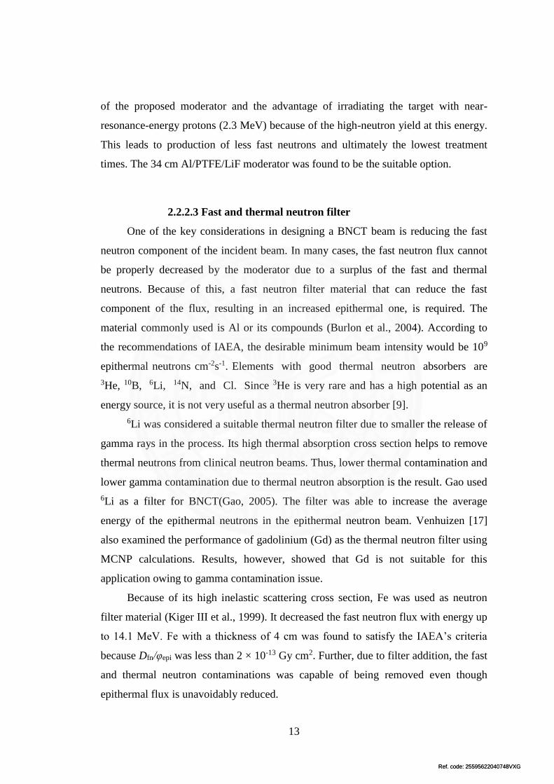
2.2.2.3 Fast and thermal neutron filter
One of the key considerations in designing a BNCT beam is reducing the fast
neutron component of the incident beam. In many cases, the fast neutron flux cannot
be properly decreased by the moderator due to a surplus of the fast and thermal
neutrons. Because of this, a fast neutron filter material that can reduce the fast
component of the flux, resulting in an increased epithermal one, is required. The
material commonly used is Al or its compounds (Burlon et al., 2004). According to
the recommendations of IAEA, the desirable minimum beam intensity would be 109
epithermal neutrons cm-2s-1. Elements with good thermal neutron absorbers are
3He, 10B, 6Li, 14N, and Cl. Since 3He is very rare and has a high potential as an
energy source, it is not very useful as a thermal neutron absorber [9].
6Li was considered a suitable thermal neutron filter due to smaller the release of
gamma rays in the process. Its high thermal absorption cross section helps to remove
thermal neutrons from clinical neutron beams. Thus, lower thermal contamination and
lower gamma contamination due to thermal neutron absorption is the result. Gao used
6Li as a filter for BNCT(Gao, 2005). The filter was able to increase the average
energy of the epithermal neutrons in the epithermal neutron beam. Venhuizen [17]
also examined the performance of gadolinium (Gd) as the thermal neutron filter using
MCNP calculations. Results, however, showed that Gd is not suitable for this
application owing to gamma contamination issue.
Because of its high inelastic scattering cross section, Fe was used as neutron
filter material (Kiger III et al., 1999). It decreased the fast neutron flux with energy up
to 14.1 MeV. Fe with a thickness of 4 cm was found to satisfy the IAEA’s criteria
because Dfn/φepi was less than 2 × 10-13 Gy cm2. Further, due to filter addition, the fast
and thermal neutron contaminations was capable of being removed even though
epithermal flux is unavoidably reduced.

Ref. code: 25595622040748VXGRef. code: 25595622040748VXG
14
Faghihi also studied many materials as the filter and recommended Al(40%) +
AlF3(60%) as the suggested filter since it has low epithermal neutron absorption cross
sections, high thermal absorption cross section and smaller radiation capture cross
section.
2.2.2.4 Reflector
A reflector is used for directing the neutrons to the beam port. For finding a
cheaper alternative reflector, Uhlar et al. tested a two-layer reflector; tungsten (W) as
the inner part and Mo as the outer part. Approximate with the same performance, the
mass of the W/Mo reflector is five times smaller than to the single component
reflector made of W.
A research work by Burlon et al. confirmed that Pb is a suitable choice as
reflector (Burlon et al., 2004). Pb has also shown better performance than graphite.
Rasouli et al. also evaluated the possibility of using Pb and BeO as the reflector
(Rasouli & Masoudi, 2012). Their different thicknesses were assessed to determine
their reflective capabilities. Pb was also used as a reflector material for D–T neutrons,
even though with a Bi collimator, spectra calculations gave similar results.
The use of graphite and boranyloxyboron (B2O) reflectors were also
investigated to increase both relative and absolute thermal-epithermal neutron fluency
(Burlon et al., 2004). The best results in terms of thermal-epithermal fluency were
obtained using a B2O reflector. For a reflector thickness of 10 cm the relative thermal-
epithermal fluency reaches a maximum value of 85%.
2.2.2.5 Collimator
A collimator is used to focus output neutron beam to the head phantom. Bi is a
commonly used material for a collimator [6]. Reflector material such as Lithium
Polyethylene in a trapezoidal shape is also occasionally used to collimate output
neutron beam.
Uhlar et al. utilized Pb supplemented with a Ni part as a collimator (Uhlář et al.,
2013). In a further study, they also employed molybdenum (Mo) supplemented with a
nickel part. This is because at low neutron energies, nickel elastic cross section is

Ref. code: 25595622040748VXGRef. code: 25595622040748VXG
15
higher than that of Mo and the Ni absorption cross section is lower than the Mo
absorption cross section for a broad energy interval of moderated neutrons.
2.2.2.6 Gamma shielding
Gamma shielding is used to reduce gamma rays originated from the nuclear
reactions and neutron capture in different BSA materials. Bi is normally used for this
purpose. For instance, Rasouli et al. employed Bi for gamma shielding (Rasouli et al.,
2012). Results showed that using 2.6 cm Bi, Dγ/φepi was able to be decreased to lower
than 2 × 10-13 Gy cm2. Thus, it is suitable for BNCT.
2.2.3 BSA Models
In this section, three BSA models for BNCT are discussed. The first one is a
BSA model proposed by Rasouli and Masoudi (figure 2.1) (Rasouli & Masoudi,
2012) are used Natural uranium as a neutron multiplier and thick layers of TiF3 and
Al2O3 as moderators. These materials are surrounded by a thick Pb reflector. Ni and
Li-Poly are used as shield and collimator, respectively. This configuration shows low
contamination of the fast and thermal neutrons and gamma at the beam port, which
satisfies almost all IAEA criteria.
Figure 2. 1 The BSA model proposed by Rasouli and Masoudi (Rasouli & Masoudi,
2012).
Rasouli and colleagues also designed BSA for BNCT based on the use of 14 cm
in radius metallic uranium as multiplier system for D–T neutron source and
moderator/filter/reflector arrangement (Rasouli et al., 2012). TiF3 with 23 cm in
thickness and Fluental with 36 cm in thickness are used for the moderator to achieve a

Ref. code: 25595622040748VXGRef. code: 25595622040748VXG
16
proper epithermal neutron flux. A configuration of 4 cm Fe, 1 mm Li, and 2.6 cm Bi
are used for fast neutron, thermal neutron, and gamma ray filters, respectively, as
illustrated in figure 2.2.
Figure 2. 2 The BSA model proposed by Rasouli et al. (Rasouli et al., 2012).
Remarks: 1 is 14 cm uranium, 2 is 23 cm TiF3, 3 is 36 cm Fluental, 4 is 4 cm Fe, 5 is
1 mm Li, 6 is 2.6 cm Bi, 7 is Pb as collimator, 8 is Pb as reflector, 9 is shield.
Rahmani and Shahriari proposed a BSA model containing layers of Mg, Al, Fe,
Pb, Bi, C, and Ni joined with their oxide and fluoride compounds as illustrated in
figure 2.3 (Rahmani & Shahriari, 2011). In this model, 10 cm of Ni is selected as a
collimator material in conical shape. Pb with 25 cm in thickness, 5% borated
polyethylene, and 1 mm Cd are used as a reflector, neutron shield, and thermal
neutron filter, respectively.
Figure 2. 3 The BSA model proposed by Rahmani and Shahriari, (Rahmani &
Shahriari, 2011).
It should be noted that as the suitable option for the treatment of deep-seated
tumors, the epithermal neutrons should possess a minimum intensity of 5 × 10⁸
n/cm2s for a reasonable time treatment. Therefore, selecting an appropriate neutron
source able to provide this epithermal flux is pivotal before undertaking BSA design.

Ref. code: 25595622040748VXGRef. code: 25595622040748VXG
17
The neutron yield of the available neutron sources capable of satisfying such criteria
is in the range of 6.6 × 10¹¹ – 4.4 × 10¹⁴ n/s (Rasouli & Masoudi, 2012).
The BNCT parameters of three configurations are presented in table 2.1. Based
on the BNCT free beam parameters of those three BSA configurations, it was found
that only the BSA designed by Rasouli et al. satisfies all IAEA criteria (Rasouli et al.,
2012). Although the BSA proposed by Rasouli and Masoudi cannot satisfy all IAEA
criteria (Rasouli & Masoudi, 2012), its neutron beam is effective for deep-seated brain
tumor treatments even with D–T neutron generator yielding as low as 2.4 × 10¹² n/s. It
was found in this configuration that with increase in the neutron source yield, the
treatment time decreases. Also, a shorter treatment time can be achieved with the cost
of high neutron source intensity. Thus, considering the trade-off between reduction of
treatment time and neutron source intensity is vital. In those three configurations, use
of specific filters is very important for removing the fast and thermal neutrons and
gamma contamination from neutron beam. However, the epithermal neutron flux is
decreased.
Table 2. 1 BNCT parameters of the three BSA configurations. BSA model φepi × 109
(n/cm2 s)
φepi/φthermal φepi/φFast Dγ/φepi ×10-13
(Gy cm2)
Dfn/φepi × 10-13
(Gy cm2)
Rahmani and
Shahriari, (Rahmani
& Shahriari, 2011)
8.19 383 17.20 1.18 7.98
Rasouli et al.
(Rasouli et al., 2012)
4.43 121.2 23.75 1.98 0.59
Rasouli and Masoudi
(Rasouli & Masoudi,
2012)
1.04 20.21 - 5.79 0.67
IAEA criteria >0.5 >100 >20 <2 <2

Ref. code: 25595622040748VXGRef. code: 25595622040748VXG
18
Chapter 3
Comparison of Existing Designs
3.1 Introduction
One of the critical parameters in BNCT is the neutron flux of a neutron source,
which must be in an appropriate rate and energy range. The neutron source providing
the required neutron beam with high neutron flux has previously seen only in a
nuclear reactor. However, a suitable nuclear reactor for such purpose is expensive and
difficult to be realized in or near urban areas. This leads to the development of other
neutron sources for BNCT. One of them is a compact neutron generator based on the
D-T fusion reaction.
Due to the fact that the typical neutron energy emitted from D-T fusion reaction
is 14.1 MeV, these neutrons cannot be used directly in BNCT. Therefore, they are
moderated to the epithermal energy range, between 1 eV and 10 keV. For this
purpose, neutrons must be treated within a particular system, called a beam shaping
assembly (BSA). By using appropriate geometry configuration and material selection
in BSA design, the quality and intensity of neutron beam can be optimized. Further,
as the intensity of the beam determines the treatment time, it must be considered in
the BSA design as well. According to the International Atomic Energy Agency
(IAEA) recommendation, epithermal neutron flux should be on the order of 109
n/cm2s.
3.2 Descriptive Of Code
In order to produce high epithermal neutron (energy range from 1 eV to 1 ×
10-2 MeV) flux from D-T neutron generators using BSA, an accurate information of
the interactions between high energy neutrons and materials are necessary. Particle
and Heavy Ions Transport code System (PHITS), as one of well-known Monte Carlo
particle transport codes (for instance: FLUKA, PHITS, GEANT4, MARS15,
MCNPX, and SHIELD), is capable of elucidating the information of the interactions
between high energy neutrons and materials. PHITS can simulate behaviours of
particles and heavy ions under influence of neutron flux over wide energy ranges and

Ref. code: 25595622040748VXGRef. code: 25595622040748VXG
19
deals with the transport of all particles (nucleons, nuclei, mesons, photons, and
electrons) over wide energy ranges, using several nuclear reaction models and nuclear
data libraries (Sato et al., 2013).
The PHITS code has been used for various research fields such as radiation
science, accelerator and its shielding design, space research, medical application, and
material research. Niita et al. (Niita et al., 2006) study three applications of the PHITS
including spallation neutron source, heavy ion therapy and space radiation. It was
shown that PHITS has great ability of carrying out the radiation transport analysis of
almost all particles including heavy ions within a wide energy range. However, use of
PHITS code for BSA designs has not been reported. Therefore, in this study, PHITS
is used to carry out a series of simulations for three BSA designs, developed for
producing an epithermal neutron flux from a D-T neutron source.
The simulations using PHITS code was performed for three BSA designs
proposed by Eskandari and Kashian (Eskandari & Kashian, 2009) (design A), Rasouli
and Masoudi (Rasouli & Masoudi, 2012) (design B), and Rasouli et al. (Rasouli et al.,
2012) (design C), to investigate their capabilities to produce epithermal neutron. The
geometry of those designs has a function to draw in 2D and 3D graphical geometry
plot definition. It is assumed in this work that all designs of BSA considered are a
cylindrical shape. In each design, it is composed of six different layers, namely,
neutron multiplier, neutron moderator, fast neutron filter, thermal neutron filter,
shielding and collimator. Furthermore, it is assumed that the neutrons are emitted
monoenergetically and the neutron yield of D-T generator is 1.45 × 10¹⁴ n/s.
3.2 Results and Discussion
Figure 3.1 (a) shows the design A, composed of 3 cm Pb as first multiplier, 2
cm U as second multiplier, 25 cm BeO as reflector, 60 cm AlF3 as moderator, and 20
cm Al as filter. The out coming value of epithermal neutron flux is calculated to be
1.73 × 10⁹ n/cm2s. A significant thermal neutron flux is, however, generated (258.2 ×
109 n/cm2s) by this simple design. Further, as can be seen from the relatively low
value of fast neutron flux (0.47 × 10⁹ n/cm2s), Al seems to be a suitable material for
filtering the fast neutron.

Ref. code: 25595622040748VXGRef. code: 25595622040748VXG
20
(a) (b)
Figure 3. 1 The BSA design (a) and neutron beam port flux per neutron source versus
energy (b) proposed by Eskandari and Kashian (Eskandari & Kashian, 2009).
Figure 3.2 (a) presents the design B. This BSA design consists of metallic
uranium as neutron multiplier, TiF3 as first moderator, Al2O3 as second moderators,
Pb as reflector, Ni as shield, and Li-Poly as collimator. The collimator is employed to
guide neutrons toward the patient position. For the purpose of having a high
epithermal neutron flux at the beam port, no filter is adopted in this design b. This
design is able to produce an epithermal neutron flux of 3.67 × 10⁹ n/cm2s. Different
from the design A, the thermal neutron flux (0.02 × 10⁹ n/cm2s) generated by the
design B is much lower than the produced epithermal neutron flux. Even the fast
neutron flux (0.47 × 10⁹ n/cm2s) is also lower than the epithermal neutron flux.
(a) (b)
Figure 3.2 The BSA design (a) and neutron beam port flux per neutron source versus
energy proposed (b) proposed by Rasouli and Masoudi (Rasouli & Masoudi, 2012).

Ref. code: 25595622040748VXGRef. code: 25595622040748VXG
21
Figure 3.3 (a) shows the design C. It is composed of 14 cm U as multiplier, 23
cm TiF3 as first moderator, 36 cm Fluental as second moderator, 4 cm Fe as fast
neutron filter, 1 mm Li as thermal neutron filter, 2.6 cm Bi as gamma shield, Pb as
collimator and reflector, LiF as shield. An epithermal neutron flux of 3.32 × 10⁹ n/cm2
s can be produced by this design. It is interesting to note that by adopting the thermal
neutron filter, the generation of thermal neutron flux can be greatly suppressed. The
design only generated 4 × 10⁶ n/cm2s of thermal neutron flux, which is much lower as
compared to that of epithermal neutron flux.
(a) (b)
Figure 3. 3 The BSA design (a) and neutron beam port flux per neutron source versus
energy (b) proposed by Rasouli et al. (Rasouli et al., 2012).
It can be seen in table 3.1 that, all the designs satisfy the International Atomic
Energy Agency (IAEA) recommended value for epithermal neutron flux, in which the
design B yields the highest value of φepi production. The values of epithermal flux are
sufficient for BNCT.

Ref. code: 25595622040748VXGRef. code: 25595622040748VXG
22
Table 3. 1 BNCT in-air parameters of the three proposed BSA.
BSA design φepi (× 109
n/cm2s)
φfast (× 109
n/cm2s)
φtherm (×
109
n/cm2s)
φepi/φfast φepi/φtherm
Design A
(Eskandari &
Kashian, 2009)
1.73 0.47 2.58 3.62 0.67
Design B
(Rasouli &
Masoudi, 2012)
3.67 2.65 0.02 1.38 179
Design C
(Rasouli et al.,
2012)
3.32 1.56 0.004 2.12 851
IAEA
(Sauerwein et
al., 2002)
>0.5 >20 >100
Although the design A uses two multiplication layers composing of Pb and U, it
shows a lower value of φepi compared to the other two designs. This suggest that,
adopting more than one layer as multiplier does not necessarily result in high φepi
since the function of multiplier is to increase the number of all types of neutron
emitted from neutron source.
It is interesting to note that, hypothetically, use of a second moderator can
reduce the number of fast neutrons and thus increase φepi/φfast. However, although
design B and design C use two moderator, the number of fast neutrons is surprisingly
higher than that in the design A, which has one moderator. It seems that selecting a
proper material for moderator is more important than adopting additional layers as
moderator. It can also be seen that a relatively high number of fast neutrons in all
three BSA designs is observed. This may be because U, as multiplier, can fairly
intensify the number of fast neutrons (Faghihi & Khalili, 2013). In addition, due to
gamma emission, U is also considered as unsuitable material for multiplier (Faghihi &
Khalili, 2013).
Furthermore, TiF3 was found to be an excellent material for a moderator in term
of neutron accumulating in epithermal energy range during the slowing down from
source energies. However, simulation results show unsuitability of TiF3 as moderator
in the design B and design C although a second moderator is also employed to reduce
the number of fast neutrons.

Ref. code: 25595622040748VXGRef. code: 25595622040748VXG
23
Fig. 3.1b, Fig. 3.2b and Fig. 3.3b show the neutron flux per neutron source
versus energy passing through the BSA. It can be seen that design A generates high
thermal neutron flux, resulting in very low of φepi/φtherm. The IAEA criterion of
φepi/φtherm is thus unable to be satisfied. Further, design C shows a very low value of
φtherm because it uses Li filter for reducing the thermal neutron.
Overall, for BNCT in terms of φepi/φfast and φepi/φtherm, the most suitable designs
are design A and C, respectively. Due to the fact that all the BSA designs can satisfy
the IAEA criteria of φepi and the difference in the value of φepi/φtherm is also much
more significant as compared to that of φepi/φfast, it suggested that design C is the most
appropriate BSA design for BNCT. It is important to note that, however, none of
those three BSA designs satisfies all the IAEA criteria.
Comparing the in-air parameters shown in Table 2.1 and Table 3.1, it is noticed
that the values are not the same for design B and design C between the previously
reported data and the present calculations. These differences in the in-air parameters
are due to the slight differences in the BSA configurations, because the exact
configuration of some BSA compounds are not provided in the previous reports.

Ref. code: 25595622040748VXGRef. code: 25595622040748VXG
24
Chapter 4
Development of BSA for BNCT
4.1 Introduction
The aim of this chapter was to develop a BSA design that is able to produce an
epithermal neutron beam with the compact neutron generator based on D-D reactions
for BNCT. An example of this type of neutron generator is a coaxial RF-driven
plasma ion source, emitting monoenergetic neutrons with Nested Option (IB-1764)
(Reijonen et al., 2005; Reijonen et al., 2002). The neutron source and BSA
configuration were modeled with Particle Heavy and Ion Transport code System
(PHITS) (Sato et al., 2013). The optimum condition for producing epithermal
neutrons was used together with the IAEA standard of neutron beams for BNCT.
Some existing BSA designs, i.e. those of Eskandari and Kashian (2009), Rasouli et al.
(2012), and Rasouli and Masoudi (2012), were also simulated with PHITS for
comparison. Finally, the output neutron beam characteristics were assessed based on
the standard free beam parameters. The standard free beam parameters are proposed
by the IAEA to define the quality of neutron beam on the beam port.
4.2. Materials and methods
A new design of BSA for a D-D nuclear fusion compact generator is proposed
in this study. The simulated D–D neutron generator was assumed to produce fast
neutrons with the energy of 2.45 MeV. In this work, it was assumed that the input fast
neutron beam possessed a diameter of 1.7 cm with a neutron flux of 1013 n/s
(Reijonen et al., 2005; Reijonen et al., 2002). A multiplier with cylindrical geometry
composed of Pb was used as the first component to increase the neutron flux. In
addition a large cross section of Pb for the (n, 2n) reaction can recompense neutron
losses due to leakage and absorption (Cerullo et al., 2002). The second component
was a moderator composed of TiF3. TiF3 was employed since materials containing
fluorine showed the ability to effectively accumulate neutrons in the epithermal
energy range during the moderation process (Eskandari & Kashian, 2009). The third
component was a second moderator composed of AlF3. By adopting a second
moderator, the ratio between epithermal neutron flux and fast neutron flux (φepi/φfast)

Ref. code: 25595622040748VXGRef. code: 25595622040748VXG
25
is expected to increase due to increased epithermal neutron flux and decreased fast
neutron flux. Further, a reflector composed of Al2O3 was placed around the multiplier
and the moderators to reflect neutrons into the multiplier and/or the moderator region.
Therefore, any leakages from these BSA regions could be minimized. Finally, Li was
used as a thermal neutron filter since thermal neutrons are detrimental to the treatment
process and are not desired at the surface of the patient. In order to obtain a suitable
BSA, the proposed BSA design was developed to fulfill the IAEA recommendation
for BNCT as shown in Table 4.1.
Table 4. 1 BNCT free beam parameters recommended by the IAEA (IAEA, 2001) φ
represents neutron flux, n stands for neutron, and s stands for second
Beam port parameters Recommended value
φepi (n/cm2 s) ~0.5 × 10⁹
φepi/φfast >20
φepi/φthermal >100
4.3 Results and discussion
As previously mentioned, BSA configuration should be appropriately optimized
to yield suitable characteristics of output neutron beam in terms of quality and
quantity. For this purpose, different materials for BSA were used and their
configurations were optimized.
4.3.1 Optimization of BSA design
A multiplier was adopted to increase the neutron flux. The Pb multiplier was
simulated with different thicknesses of 2, 4, 8, 10, and 12 cm. As seen in Figure 4.1,
the epithermal neutron flux varied greatly with respect to the thickness of Pb. The Pb
multiplier with a thickness of 4 cm was found to be the best choice for the multiplier.
It produced the highest epithermal neutron flux of 2.75 × 10⁻⁷ 1/cm2/source.

Ref. code: 25595622040748VXGRef. code: 25595622040748VXG
26
Figure 4. 1 Epithermal neutron flux per neutron source for different thicknesses of Pb
as the multiplier.
In order to moderate the produced neutrons to the epithermal range after being
multiplied by Pb, TiF3 was adopted as the first moderator with 4 cm of Pb as the
multiplier. Different thicknesses of TiF3 ranging from 4 to 36 cm with an interval
value of 4 cm were optimized. With increased thickness of TiF3 from 4 cm to 20 cm,
the epithermal neutron flux increased from 5.81 × 10⁻⁶ 1/cm2/source to 1.16 × 10⁻⁴
1/cm2/source. Further increase of the TiF3 thickness to 36 cm decreased the
epithermal neutron flux to 4.95 × 10⁻⁵ 1/cm2/source. As shown in Figure 4.2,
insignificant difference of the epithermal flux between 16 and 20 cm of TiF3 was
observed. For this reason, 16 cm of TiF3 was selected as the first moderator. By
adopting 16 cm of TiF3 as the moderator, the epithermal neutron flux was
unfortunately still very low. This resulted in a very low value of φepi/φfast of 4.94×10².
To increase the value of φepi/φfast, a second moderator was further adopted.

Ref. code: 25595622040748VXGRef. code: 25595622040748VXG
27
Figure 4. 2 Epithermal neutron flux per neutron source for different thicknesses of
TiF3 as the first moderator
For the second moderator, AlF3 was adopted. Pb with 4 cm thickness and TiF3
with 16 cm thickness were used as the multiplier and the first moderator, respectively.
The trend of φepi/φfast values was similar to that of epithermal neutron flux for the first
moderator. That is, as the thickness of AlF3 increases from 4 cm to 60 cm, φepi/φfast
increases from 9.77 × 10⁻² to 24.6. With further increase of the AlF3 thickness to 60
cm, φepi/φfast drastically decreased to 6.27. Therefore, 60 cm of AlF3 was chosen as the
second moderator as shown in Figure 4.3. It was found that by adopting 60 cm of
AlF3 as the second moderator, the fast neutron flux was significantly reduced,
indicated by a high value of φepi/φfast of 24.6. Due to this fact, the fast neutron filter
was not required for the proposed BSA design.

Ref. code: 25595622040748VXGRef. code: 25595622040748VXG
28
Figure 4. 3 φepi/φfast for different thicknesses of AlF3 as the second moderator.
To reflect the produced neutrons into the multiplier region and the moderator
region, a reflector with Al2O3 was adopted. A configuration of 4 cm of Pb as the
multiplier, 16 cm of TiF3 as the first moderator, and 60 cm of AlF3 as the second
moderator was applied. Different thicknesses of Al2O3 (25, 30, and 35 cm) were
evaluated to determine their reflective capabilities. The φepi/φfast values for 25, 30, and
35 cm thickness of Al2O3 were calculated to be 17.8, 26.3, and 25.9, respectively.
Thus, 30 cm of Al2O3 was adopted as the reflector. However, it should be noted that
the φepi/φthermal value of Al2O3 with 30 cm thickness was still relatively low and did
not meet the IAEA’s recommended value (Table 1). The φepi/φthermal values for 25, 30,
and 35 cm thickness of Al2O3 were 6.78, 3.3, and 2.61, respectively. This indicated
that the thermal neutron flux was still high. Thermal neutrons are undesirable as they
can introduce too high radiation dose to the soft tissue. For this reason, a thermal
neutron filter was adopted.
For the purpose of reducing the thermal neutron flux and increasing the
epithermal flux, Li was adopted as the thermal neutron filter. The natural Li possesses
a large thermal neutron absorption cross section of 940 barns. A configuration of 4 cm
of Pb as the multiplier, 16 cm of TiF3 as the first moderator, 60 cm of AlF3 as the
second moderator, and 30 cm of Al2O3 as the reflector was used. Different thicknesses

Ref. code: 25595622040748VXGRef. code: 25595622040748VXG
29
of Li (1, 2, 3, and 4 cm) were investigated to find the suitable thickness, indicated by
the larger value of φepi/φthermal. As can be seen in Figure 4.4a, with the increase of Li
thickness from 1 cm to 4 cm, the φepi/φthermal value continuously increased from 26.2
to 174. All of these φepi/φthermal values complied with the IAEA recommended value.
Therefore, to select the most appropriate Li thickness, another free beam parameter
for BNCT, namely, φepi/φfast was considered. As shown in Figure 4.4b, 3 cm of Li
exhibited the highest φepi/φfast value of 27. Thus, 3 cm of Li was opted as the thermal
neutron filter.
Figure 4. 4 φepi/φthermal (a) and φepi/φfast (b) for different thicknesses of Li as the
thermal neutron filter.
b)

Ref. code: 25595622040748VXGRef. code: 25595622040748VXG
30
Overall, the proposed BSA configuration for fast neutrons from a compact
neutron source based on D-D nuclear fusion reactions consisted of 4 cm of Pb as the
multiplier, 16 cm of TiF3 as the first moderator, 60 cm of AlF3 as the second
moderator, 30 cm of Al2O3 as the reflector, and 3 cm of Li as the thermal filter
(Figure 4.5a). The φepi/φfast and φepi/φthermal values of the proposed BSA, which
represented the quality of the free beam parameters, were 27 and 126, respectively.
The values of these parameters satisfied the IAEA recommended values for BNCT.
The results showed that materials containing fluorine, which were adopted as the first
moderator (TiF3) and the second moderator (AlF3), were suitable to increase the
epithermal neutron flux. Additionally, by adopting materials containing fluorine, the
fast neutron flux was significantly reduced. Thus, no fast neutron filter was needed for
the proposed BSA design. Moreover, Li was proven to be a proper material choice to
reduce the thermal neutron flux. Although the quality of the neutron beam was in
agreement with the IAEA criteria, the intensity of epithermal neutrons was still below
the recommended value. By taking a neutron yield of 1013 n/s generated from the
simulated D-D neutron source, the epithermal neutron flux at the beam port of the
proposed BSA facility was found to be only 2.66 × 10⁷ n/cm2s (Figure 4.5b). This is
because D-D neutron generators typically produce low neutron flux as compared to
other neutron sources, such as nuclear reactors or D-T neutron generators.
Improvement may be possible through material selection and source capacity
enhancement.
(a) (b)
Figure 4. 5 The proposed BSA design (a) and the neutron flux per neutron source at the
beam port exit versus neutron energy (b).

Ref. code: 25595622040748VXGRef. code: 25595622040748VXG
31
4.3.2. Comparison of BSA designs
For the purpose of comparison, the BSA designs proposed by Eskandari and
Kashian (2009), Rasouli et al. (2012), and Rasouli and Masoudi (2012), were also
taken into consideration, which for the sake of simplicity were indicated as design A,
design B, and design C, respectively. Figure 4.6a shows the design A, composed of 3
cm of Pb as the first multiplier, 2 cm of U as the second multiplier, 25 cm of BeO as
the reflector, 60 cm of AlF3 as the moderator, and 20 cm of Al as the fast filter. The
out coming value of epithermal neutron flux was calculated to be 5.05 × 10⁷ n/cm2 s
(Figure 4.6b). The φepi/φfast and φepi/φtherm values of design A were 19.5 and 0.57,
respectively. Therefore, no free beam parameter of design A was found to meet the
IAEA recommended values.
(a) (b)
Figure 4. 6 The BSA design A (a) and the neutron flux per neutron source at the beam
port exit versus energy (b). The BSA design was proposed by Eskandari and Kashian
(2009).
Figure 4.7a presents the design B, consisting of 14 cm of U as the neutron
multiplier, 20 cm of TiF3 as the first moderator, 22 cm of Al2O3 as the second
moderator, 105 cm of Pb as the reflector, 69 cm of Ni as the gamma shield, and 10 cm
of Li-Poly as the collimator. The collimator was used to guide neutrons toward the
patient position. For obtaining a high epithermal neutron flux at the beam port exit, no
filter was adopted in the design B. This BSA configuration could produce an
epithermal neutron flux of 8.44 × 10⁷ n/cm2s. However, as seen in Figure 4.7b, the
thermal neutron flux was much lower than the epithermal neutron flux. The similar
trend was also found for the fast neutron flux. It was still lower than the epithermal

Ref. code: 25595622040748VXGRef. code: 25595622040748VXG
32
neutron flux. As a result, the φepi/φfast value of 1.95 was far from the IAEA’s
recommended value, while the φepi/φtherm value of 104 was only slightly higher than
the recommended value.
(a) (b)
Figure 4. 7 The BSA design B (a) and neutron flux per neutron source at the beam port
exit versus energy proposed (b). The BSA design was proposed by Rasouli and Masoudi
(2012).
Figure 4.8a shows the design C, composed of 14 cm of U as the multiplier, 23
cm of TiF3 as the first moderator, 36 cm of Fluental as the second moderator, 4 cm of
Fe as the fast neutron filter, 1 mm of Li as the thermal neutron filter, 2.6 cm of Bi as
the gamma shield, Pb as the collimator and the reflector, and LiF as the neutron
shield. The epithermal neutron flux of 7.74 × 10⁷ n/cm2 s could be produced by this
BSA design (Figure 4.8b). By adopting Li as the thermal neutron filter, the generation
of thermal neutron flux could be greatly suppressed. This led to a very high value of
φepi/φthermal of 1240. A similar result was also observed in our proposed BSA design.
Adopting Li as the thermal neutron filter reduced the thermal neutron flux, resulting
in a relatively high value of φepi/φthermal. Li seemed to be a suitable material choice for
the thermal neutron filter. On the contrary, Fe was found to show a poor performance
for removing fast neutrons, indicated by a low value of φepi/φfast of 4.84.

Ref. code: 25595622040748VXGRef. code: 25595622040748VXG
33
(a) (b)
Figure 4. 8 The BSA design C (a) and neutron flux per neutron source at beam port exit
versus energy (b). The BSA design was proposed by Rasouli et al. (2012).
Comparing the proposed BSA design with some other BSA designs developed
by Eskandari and Kashian (2009), Rasouli et al. (2012), and Rasouli and Masoudi
(2012), it was found that our design showed a better performance in terms of φepi/φfast.
The value of φepi/φfast also satisfied the IAEA criterion for φepi/φfast. Among all BSA
designs investigated, the design C produced the highest value of φepi/φthermal, which
was even much higher than the minimum value recommended by the IAEA.
Furthermore, the design B showed the highest value of epithermal neutron flux since
it had no thermal neutron filter. However, the epithermal neutron flux was still below
the recommended value. The BNCT free beam parameters of the investigated BSA
designs with the D-D neutron source are summarized in Table 4.2.
Table 4. 2 BNCT free beam parameters of each BSA designs for D-D neutrons
BSA design φepi (× 107 n/cm2 s) φepi/φfast φepi/φthermal
This work 2.66 27 126
Design A 5.05 19.5 0.57
Design B 8.44 1.9 104
Design C 7.74 4.8 1240
IAEA >50 >20 >100
It is interesting to note that, although the design A used two multiplication
layers composing of Pb and U, it showed a lower value of φepi compared to the design
B and the design C. This suggested that, adopting more than one layer as a multiplier
did not necessarily result in higher epithermal flux. Moreover, it is known that use of

Ref. code: 25595622040748VXGRef. code: 25595622040748VXG
34
a second moderator typically leads to reduction of the number of fast neutrons and
increased φepi/φfast. However, although the design B and the design C used two
moderators, the number of fast neutrons was surprisingly higher than that of the
design A, which had only a single moderator. Therefore, selecting a proper material as
the moderator is more important than adopting additional layers as the moderator.
Moreover, high numbers of fast neutrons; and thus low values of φepi/φfast, in the
design A, the design, B, and the design C, were observed. This implied that, using U,
as the multiplier, intensified the number of fast neutrons, which is detrimental to the
neutron beam quality, and therefore U is unsuitable to be used as the multiplier
material. Employing Pb as the multiplier material seemed to be promising, as it was
evidenced in the proposed BSA design. The φepi/φfast value of 27 of the proposed BSA
satisfied the IAEA value for BNCT.
Overall, by using the proposed BSA design as well as the design C, the quality
of neutron beam was satisfying. However, the quantity of the epithermal neutron still
need to be enhanced as no BSA designs satisfied the recommended value for BNCT.
The low quantity of epithermal neutrons was due to the relatively low D-D neutron
output of only 1013 n/s. Similar results on the BSA designs based on D-D neutron
generators were also reported (Durisi et al., 2007; Fantidis et al., 2013). The
epithermal neutron flux produced by those BSA designs was also below the IAEA
recommended value for clinical treatment.

Ref. code: 25595622040748VXGRef. code: 25595622040748VXG
35
Chapter 5
Conclusion
5.1 Conclusion
Three existing BSA designs were evaluated to moderate fast neutron from D-T
neutron source for BNCT. They have φepi values satisfying the IAEA criteria.
According to the simulations and performed calculations, the BSA design proposed
by Rasouli et al. (2012) yields the best performance. It produces epithermal neutron
flux of 3.32 × 10⁹ n/cm2 s in the range suggested by the IAEA and φepi/φfast of 851 and
efficiently reduces fast neutron into appropriate level. Moreover, it exhibits a very low
value of φtherm since it uses Li filter for reducing the thermal neutron. With the same
design using D-D neutron source, an epithermal neutron flux of 7.74 × 10⁷ n/cm2 s
and φepi/φfast of 4.8 can be produced. Interestingly, a very high φepi/φthermal of 1240 is
obtained. However, none of those three BSA design satisfies all the IAEA criteria.
A new BSA design for slowing down fast neutrons to the epithermal energy
range from a D-D neutron generator was furthermore designed for BNCT. An
optimum design of BSA consisted of 4 cm of Pb as the multiplier, 16 cm of TiF3 as
the first moderator, 60 cm of AlF3 as the second moderator, 30 cm of Al2O3 as the
reflector, and 3 cm of Li as the thermal filter. The proposed BSA with the D-D
neutron generator with a neutron yield of 1013 n/s produced an epithermal neutron
flux of 2.66 × 10⁷ n/cm2 s, φepi/φfast of 27, and φepi/φthermal of 126. The obtained values
of free beam parameters satisfied those recommended by IAEA, except the epithermal
neutron flux. This was because D-D neutron generators produce relatively low
neutron flux as compared to nuclear reactors and D-T neutron generators. Despite this
fact, D-D neutron generators were shown to be applicable for achieving appropriate
quality of neutron beam and thus the proposed BSA design with an improved
performance of D-D neutron generators could be applied for BNCT purpose. In order
to achieve the minimum quantity of neutron flux required for BNCT, one should
employ, or develop if it has not yet been available, a D-D neutron generator capable
of producing a neutron yield of more than 1015 n/s.

Ref. code: 25595622040748VXGRef. code: 25595622040748VXG
36
5.2 Recommendation and future work
To obtain BSA with better performance which can satisfy all the IAEA
criteria, more parameters such as geometry and type of material need to be
further investigated.
To obtain more comprehensive results, the angular energy spectra need to be
measure. For this purpose, the neutron angular distribution at different angle
should be measured.
To realize more effective BSA design, in-phantom parameters need to be
determined, besides in-air parameters.
To be able to use the proposed BSA design with satisfied results in term of
both quality and quantity of the neutron flux, a D-D neutron generator capable
of producing a neutron yield of more than 1015 n/s should be employed.

Ref. code: 25595622040748VXGRef. code: 25595622040748VXG
37
References
Barth, R.F., Coderre, J.A., Vicente, M.G.H., Blue, T.E. 2005. Boron neutron capture
therapy of cancer: current status and future prospects. Clinical Cancer
Research, 11(11), 3987-4002.
Barth, R.F., Soloway, A.H., Goodman, J.H., Gahbauer, R.A., Gupta, N., Blue, T.E.,
Yang, W., Tjarks, W. 1999. Boron neutron capture therapy of brain tumors: an
emerging therapeutic modality. Neurosurgery, 44(3), 433-450.
Barth, R.F., Yang, W., Rotaru, J.H., Moeschberger, M.L., Joel, D.D., Nawrocky,
M.M., Goodman, J.H., Soloway, A.H. 1997. Boron neutron capture therapy of
brain tumors: enhanced survival following intracarotid injection of either
sodium borocaptate or boronophenylalanine with or without blood-brain
barrier disruption. Cancer Research, 57(6), 1129-1136.
Burlon, A., Kreiner, A., Valda, A., Minsky, D. 2004. An optimized neutron-beam
shaping assembly for accelerator-based BNCT. Applied radiation and
isotopes, 61(5), 811-815.
Capala, J., Britta, H., Sköld, K., af Rosenschöld, P.M., Giusti, V., Persson, C., Wallin,
E., Brun, A., Franzen, L., Carlsson, J. 2003. Boron neutron capture therapy for
glioblastoma multiforme: clinical studies in Sweden. Journal of neuro-
oncology, 62(1), 135-144.
Cerullo, N., Esposito, J., Daquino, G. 2004. Spectrum shaping assessment of
accelerator-based fusion neutron sources to be used in BNCT treatment.
Nuclear Instruments and Methods in Physics Research Section B: Beam
Interactions with Materials and Atoms, 213, 641-645.
Cerullo, N., Esposito, J., Leung, K.N., Custodero, S. 2002. An irradiation facility for
Boron Neutron Capture Therapy application based on a radio frequency driven
D–T neutron source and a new beam shaping assembly. Review of scientific
instruments, 73(10), 3614-3618.
Clegg, L.X., Li, F.P., Hankey, B.F., Chu, K., Edwards, B.K. 2002. Cancer survival
among US whites and minorities: a SEER (Surveillance, Epidemiology, and
End Results) Program population-based study. Archives of Internal Medicine,
162(17), 1985-1993.
Coderre, J.A., Chanana, A.D., Joel, D.D., Elowitz, E.H., Micca, P.L., Nawrocky,
M.M., Chadha, M., Gebbers, J.-O., Shady, M., Peress, N.S. 1998.
Biodistribution of boronophenylalanine in patients with glioblastoma
multiforme: boron concentration correlates with tumor cellularity. Radiation
research, 149(2), 163-170.
Daumas‐Duport, C., Scheithauer, B., O'Fallon, J., Kelly, P. 1988. Grading of
astrocytomas: a simple and reproducible method. Cancer, 62(10), 2152-2165.
de Boer, J.J. 2008. New Filter Design with Monte Carlo Calculation. Faculty of
Applied Physics, TU Delft.
Durisi, E., Zanini, A., Manfredotti, C., Palamara, F., Sarotto, M., Visca, L., Nastasi,
U. 2007. Design of an epithermal column for BNCT based on D–D fusion
neutron facility. Nuclear Instruments and Methods in Physics Research
Ref. code: 25595622040748VXGRef. code: 25595622040748VXG
38
Section A: Accelerators, Spectrometers, Detectors and Associated Equipment,
574(2), 363-369.
Eskandari, M., Kashian, S. 2009. Design of moderator and multiplier systems for D–T
neutron source in BNCT. Annals of Nuclear Energy, 36(8), 1100-1102.
Fantidis, J., Saitioti, E., Bandekas, D., Vordos, N. 2013. Optimised BNCT facility
based on a compact DD neutron generator. Int J Radiat Res, 11, 207-14.
Faghihi, F., Khalili, S. 2013. Beam shaping assembly of a D–T neutron source for
BNCT and its dosimetry simulation in deeply-seated tumor. Radiation Physics
and Chemistry, 89, 1-13.
Gao, W. 2005. Lithium-6 filter for a fission converter-based boron neutron capture
therapy irradiation facility beam, Massachusetts Institute of Technology.
IAEA. 2001. Current status of neutron capture therapy. IAEA-TECDOC-1223.
Jones, P.A., Baylin, S.B. 2007. The epigenomics of cancer. Cell, 128(4), 683-692.
Kabalka, G.W., Smith, G.T., Dyke, J.P., Reid, W.S. 1997. Evaluation of fluorine-18-
BPA-fructose for boron neutron capture treatment planning. The Journal of
Nuclear Medicine, 38(11), 1762.
Kerr, J.F., Winterford, C.M., Harmon, B.V. 1994. Apoptosis. Its significance in
cancer and cancer therapy. Cancer, 73(8), 2013-2026.
Kiger III, W., Sakamoto, S., Harling, O. 1999. Neutronic design of a fission
converter-based epithermal neutron beam for neutron capture therapy. Nuclear
science and engineering, 131(1), 1-22.
Koivunoro, H., Auterinen, I., Kosunen, A., Kotiluoto, P., Seppälä, T., Savolainen, S.
2003. Computational study of the required dimensions for standard sized
phantoms in boron neutron capture therapy dosimetry. Physics in medicine
and biology, 48(21), N291.
Leung, K.-N. 2009. Cylindrical neutron generator, Google Patents.
Miyamaru, H., Murata, I. 2011. Neutron and gamma-ray dose evaluation on
accelerator neutron source using p-Li reaction for BNCT. Prog. Nucl. Sci.
Technol, 1, 533-536.
Miyatake, S.-I., Kawabata, S., Yokoyama, K., Kuroiwa, T., Michiue, H., Sakurai, Y.,
Kumada, H., Suzuki, M., Maruhashi, A., Kirihata, M. 2009. Survival benefit
of Boron neutron capture therapy for recurrent malignant gliomas. Journal of
neuro-oncology, 91(2), 199-206.
Mukundan, S., Holder, C., Olson, J.J. 2008. Neuroradiological assessment of newly
diagnosed glioblastoma. Journal of neuro-oncology, 89(3), 259-269.
Nakagawa, Y., Kageji, T. 2012. Tolerance of Healthy Tissues and Ideal Radiation
Dose on BNCT. in: Neutron Capture Therapy, Springer, pp. 359-365.
Niita, K., Sato, T., Iwase, H., Nose, H., Nakashima, H., Sihver, L. 2006. PHITS—a
particle and heavy ion transport code system. Radiation measurements, 41(9),
1080-1090.
Parsons, D.W., Jones, S., Zhang, X., Lin, J.C.-H., Leary, R.J., Angenendt, P.,
Mankoo, P., Carter, H., Siu, I.-M., Gallia, G.L. 2008. An integrated genomic
analysis of human glioblastoma multiforme. Science, 321(5897), 1807-1812.
Rahmani, F., Shahriari, M. 2011. Beam shaping assembly optimization of Linac based
BNCT and in-phantom depth dose distribution analysis of brain tumors for
verification of a beam model. Annals of Nuclear Energy, 38(2), 404-409.

Ref. code: 25595622040748VXGRef. code: 25595622040748VXG
39
Rasouli, F.S., Masoudi, S.F. 2012. Design and optimization of a beam shaping
assembly for BNCT based on D–T neutron generator and dose evaluation
using a simulated head phantom. Applied Radiation and Isotopes, 70(12),
2755-2762.
Rasouli, F.S., Masoudi, S.F., Kasesaz, Y. 2012. Design of a model for BSA to meet
free beam parameters for BNCT based on multiplier system for D–T neutron
source. Annals of Nuclear Energy, 39(1), 18-25.
Reijonen, J., Gicquel, F., Hahto, S., King, M., Lou, T.-P., Leung, K.-N. 2005. D–D
neutron generator development at LBNL. Applied Radiation and Isotopes,
63(5), 757-763.
Reijonen, J., Leung, K., Jones, G. 2002. RF ion source development for neutron
generation and for material modification. Review of scientific instruments,
73(2), 934-936.
Roa, W., Brasher, P., Bauman, G., Anthes, M., Bruera, E., Chan, A., Fisher, B.,
Fulton, D., Gulavita, S., Hao, C. 2004. Abbreviated course of radiation therapy
in older patients with glioblastoma multiforme: a prospective randomized
clinical trial. Journal of clinical oncology, 22(9), 1583-1588.
Sato, T., Niita, K., Matsuda, N., Hashimoto, S., Iwamoto, Y., Noda, S., Ogawa, T.,
Iwase, H., Nakashima, H., Fukahori, T. 2013. Particle and heavy ion transport
code system, PHITS, version 2.52. Journal of Nuclear Science and
Technology, 50(9), 913-923.
Sauerwein, W., Zurlo, A., Group, E.B.N.C.T. 2002. The EORTC boron neutron
capture therapy (BNCT) group: achievements and future projects. European
Journal of Cancer, 38, 31-34.
Stavros, A.T., Thickman, D., Rapp, C.L., Dennis, M.A., Parker, S.H., Sisney, G.A.
1995. Solid breast nodules: use of sonography to distinguish between benign
and malignant lesions. Radiology, 196(1), 123-134.
Stupp, R., Mason, W.P., Van Den Bent, M.J., Weller, M., Fisher, B., Taphoorn, M.J.,
Belanger, K., Brandes, A.A., Marosi, C., Bogdahn, U. 2005. Radiotherapy
plus concomitant and adjuvant temozolomide for glioblastoma. New England
Journal of Medicine, 352(10), 987-996.
Sweet, W.H. 1951. The uses of nuclear disintegration in the diagnosis and treatment
of brain tumor. New England Journal of Medicine, 245(23), 875-878.
Uhlář, R., Alexa, P., Pištora, J. 2013. A system of materials composition and
geometry arrangement for fast neutron beam thermalization: An MCNP study.
Nuclear Instruments and Methods in Physics Research Section B: Beam
Interactions with Materials and Atoms, 298, 81-85.
Verbeke, J., Leung, K., Vujic, J. 2000. Development of a sealed-accelerator-tube
neutron generator. Applied Radiation and Isotopes, 53(4), 801-809.
Yamamoto, T., Tsuboi, K., Nakai, K., Kumada, H., Sakurai, H., Matsumura, A. 2013.
Boron neutron capture therapy for brain tumors. Translational Cancer
Research, 2(2), 80-86.
Ref. code: 25595622040748VXGRef. code: 25595622040748VXG
40
Appendices
Appendix A
Comparison of Existing Design
1. The BSA design proposed by Eskandari and Kashian
1.1. Input file
[title]
Example 1: Get started
$ "D" = default value
$ Comments with '$', '#', 'c'
$
%%%%%%%%%%%%%%%%%%%%%%%%%%%%%%%%%%%%%%%%%
%%%%%%%%%%
[parameters] $ Simulation parameters
file(6) = phits.out $ Output filename
maxcas = 1e7 $ Number of events per batch
maxbch = 1 $ Number of batch
imout = 2 $ Option of material representation in [material] 2:MCNP-type
icntl = 0 $ (D=0)Calculation mode: 0=real simulation, 5=no reactions
(void all), 6=source check, 8=check geometry
itall = 1 $ (D=0) Tally ouput after every batch. D=0 not output, D=1
output in same file
$ Cut-off energy
emin(1) = 1.0e-3 $ (D=1.0) cut-off energy for proton (MeV)
emin(2) = 1.e-10 $ (D=1.0) cut-off energy for neutron (MeV)
emin(12) = 1.e-1 # (D=1.d9) cut-off energy of electron (MeV)
emin(13) = 1.e-1 # (D=1.d9) cut-off energy of positron (MeV)
emin(14) = 1.e-3 # (D=1.d9) cut-off energy of photon (MeV)
emin(15) = 2.0e-3 # (D=1.d9) cut-off energy of deuteron (MeV/nucleon)
emin(16) = 3.0e-3 # (D=1.d9) cut-off energy of triton (MeV/nucleon)
emin(17) = 3.0e-3 # (D=1.d9) cut-off energy of 3He (MeV/nucleon)
emin(18) = 4.0e-3 # (D=1.d9) cut-off energy of Alpha (MeV/nucleon)
emin(19) = 1.0e-3 # (D=1.d9) cut-off energy of Heavy Ion (MeV/nucleon)
$ Maximum energy of nulcear data library used
$ By default, PHITS omits electron/positron/photon transport & uses Boltzmann
transport for low-energy neutrons (<20MeV)
dmax(2) = 20.0 $ Neutron
dmax(12) = 1.0 $ Electron
dmax(13) = 1.0 $ positron
dmax(14) = 1.0 $ photon

Ref. code: 25595622040748VXGRef. code: 25595622040748VXG
41
$ Option for nuclear reactions
e-mode = 1 $ (D=0) Option for event-generator: 0=OFF, 1=ON
igamma = 1 $ (D=0) Option for gamma decay for residual nuclei: 0=no
decay, 1=use 'trxcrd.dat', 2=EBITIM model, 3=EBITIM+isomer production
ipnint = 1 $ (D=0) Option for photonuclear reaction: 0=OFF, 1=ON
file(7) = data/xsdir.jnd $ Cross section data library for low energy neutrons
file(14)= data/trxcrd.dat $ Cross section data library for photon emission from
residual nuclei
$ Option for charged particle transport
nedisp = 1 $ (D=0) Energy straggling: 0=OFF, 1=Landau-Vavilov
nspred = 2 $ (D=0) Angle straggling: 0=OFF, 2=Moliere First Coulomb
diffusion
itstep = 1 $ (D=0) Option for timing tally "correct" curvature for
momentum changing trajectory e.g. in magnetic field
$
%%%%%%%%%%%%%%%%%%%%%%%%%%%%%%%%%%%%%%%%%
%%%%%%%%%%
[source]
s-type = 1 % Source type: 1=cylinder, 2=rectangular, 9=spherical
proj = 2112 % Projectile: 2112=neutron
dir = 1 % Initial direction relative to positive-z axis: dir=cosine
e0 = 14.1 % Initial energy (MeV)
x0 = 0
y0 = 0
z0 = -1. % zmin (cm)
z1 = -1. % zmax: z1=z0 circle plan source
r0 = 1.7 % radius of the cylindrical source
$
%%%%%%%%%%%%%%%%%%%%%%%%%%%%%%%%%%%%%%%%%
%%%%%%%%%%
[material]
$ Material composition info: nuclei & density
$ Density can be defined in [cell], then in [material] you only need to define material
compositions
$ i.e. weight fractions, if density is defined in g/cm^3, or atomic fractions if density in
10^24 atoms/cm^3
$ Library number and data class in "data/xsdir.jnd"
MAT[1] $ Lead, den = 11.35 g/cc
82204.50c -0.01378
82206.50c -0.23955
82207.50c -0.22074
82208.50c -0.52592

Ref. code: 25595622040748VXGRef. code: 25595622040748VXG
42
MAT[2] $ Uranium 238, den = 18.95g/cc
92234.50c -0.000057
92235.50c -0.007204
92238.50c -0.992739
MAT[3] $ Beryllium Oxide, den = 3.01 g/cc
4009.50c -0.360320
8016.50c -0.639680
MAT[4] $ Aluminium Fluoride, den = 2.88 g/cc
13027.50c -0.32130
9019.50c -0.67870
MAT[5] $ Aluminium, den= 2.6989 g/cc
13027.50c -1.0000
MAT[6] $ Dry air, den=0.001205g/cc
6000.50c -0.000124
7014.50c -0.752291
7015.50c -0.002977
8016.50c -0.231781
18040.50c -0.012827
$
%%%%%%%%%%%%%%%%%%%%%%%%%%%%%%%%%%%%%%%%%
%%%%%%%%%
[mat name color]
mat name size color
0 void 1 white
1 Pb 1 yellow
2 U 1 red
3 BeO 1 pastelblue
4 AlF3 1 brown
5 Al 1 pastelpink
6 Air 1 pastelcyan
$
%%%%%%%%%%%%%%%%%%%%%%%%%%%%%%%%%%%%%%%%%
%%%%%%%%%%
[ S u r f a c e ]
10 so 500.
11 cz 20. $ Pb
12 pz 0. $ Pb
13 pz 3. $ Pb
14 cz 20. $ U

Ref. code: 25595622040748VXGRef. code: 25595622040748VXG
43
15 pz 3. $ U
16 pz 7. $ U
17 cz 45. $ BeO
18 pz 0. $ BeO
19 pz 87. $ BeO
20 cz 20. $ Alf3
21 pz 7. $ AlF3
22 pz 67. $ AlF3
23 cz 20. $ Al
24 pz 67. $ Al
25 pz 87. $ Al
26 sph 0 0 0 1. $ sphere radius 1 cm
$
%%%%%%%%%%%%%%%%%%%%%%%%%%%%%%%%%%%%%%%%%
%%%%%%%%%%
[cell]
$ If density is positive: unit 10^24 atoms/cm^3 (= atoms/barn/cm)
$ If density is negative: unit g/cm^3
$id mat den surface
100 -1 10
101 1 -11.35 -11 12 -13
102 2 -18.95 -14 15 -16
103 3 -3.01 -17 18 -19 #101 #102 #104 #105
104 4 -2.88 -20 21 -22
105 5 -2.6989 -23 24 -25
106 6 -0.001205 -26 trcl=(0 0 88) $ detector
110 0 -10 #101 #102 #103 #104 #105 #106 $ working area
$
%%%%%%%%%%%%%%%%%%%%%%%%%%%%%%%%%%%%%%%%%
%%%%%%%%%%
[volume]
reg vol
101 3.768e3 $ cell 1
102 5.024e3 $ cell 2
103 4.439175e5 $ cell 3
104 7.536e4 $ cell 4
105 2.512e4 $ cell 5
106 4.19 $ cell 6
$
%%%%%%%%%%%%%%%%%%%%%%%%%%%%%%%%%%%%%%%%%
%%%%%%%%%%
[ T - product ]off $ Check product-eng

Ref. code: 25595622040748VXGRef. code: 25595622040748VXG
44
mesh = reg
reg = {101-105}
e-type = 3 $ (=3) log scale
ne = 50
emin = 1.e-8
emax = 100. $ MeV
mother = all
part = Neutron Photon
unit = 1 $ 1/source
axis = eng
file = product-eng.dat
gshow = 3
epsout = 1
resol = 1
[t-track] off $xy: check geometry
$Region crossing tally
mesh = xyz
z-type = 1
nz = 3
-5 0 10 20 30 45
x-type = 2
nx = 100
xmin = -15
xmax = 15
y-type = 2
ny = 100
ymin = -15
ymax = 15
e-type = 3 $ All energies
ne = 1
emin = 1e-8
emax = 1e2 $ MeV
part = Neutron Photon $ 2112=neutron 22=photon
unit = 1 $ 1/cm^2/source

Ref. code: 25595622040748VXGRef. code: 25595622040748VXG
45
axis = xy
file = track-xy.dat $ all particles in one diagram
gshow = 3 $ 2: region boundary & material name; 3: region
boundary and name
epsout = 1
resol = 1
$
%%%%%%%%%%%%%%%%%%%%%%%%%%%%%%%%%%%%%%%%%
%%%%%%%%%%
[t-track] off $yz: check geometry
$Region crossing tally
mesh = xyz
x-type = 1
nx = 3
-5 -0 +30 +50
y-type = 2
ny = 100
ymin = -50
ymax = 50
z-type = 2
nz = 100
zmin = -5
zmax = 100
e-type = 3 $ All energies
ne = 1
emin = 1e-8
emax = 1e2 $ MeV
part = Neutron $ 2112=neutron 22=photon
unit = 1 $ 1/cm^2/source
axis = yz
file = track-yz.dat $ all particles in one diagram
gshow = 3 $ 2: region boundary & material name; 3: region
boundary and region name
epsout = 1
resol = 1
$
%%%%%%%%%%%%%%%%%%%%%%%%%%%%%%%%%%%%%%%%%
%%%%%%%%%%

Ref. code: 25595622040748VXGRef. code: 25595622040748VXG
46
[T-track] $ Tally particle energies in detectors
$ Region crossing tally
mesh = reg
reg = {101-106}
e-type = 3 $ (=3) log scale
ne = 50
emin = 1.e-8
emax = 100. $ MeV
part = Neutron $ 2112=neutron, 22=photon, 2212=proton
unit = 1 $ 1/cm^2/source
axis = eng
file = track-reg-eng-1e7.dat $ all particles in one diagram
gshow = 3 $ 2: region boundary & material name; 3: region
boundary and name
epsout = 1
resol = 1
$
%%%%%%%%%%%%%%%%%%%%%%%%%%%%%%%%%%%%%%%%%
%%%%%%%%%%
[ T - product ] off $ Check source xy
mesh = xyz
z-type = 1
nz = 3
-5 0 10 20 30 45
x-type = 2
nx = 100
xmin = -30
xmax = 30
y-type = 2
ny = 100
ymin = -30
ymax = 30
e-type = 3 $ All energies
ne = 1
emin = 1.e-8
emax = 100.0 $ MeV
part = neutron

Ref. code: 25595622040748VXGRef. code: 25595622040748VXG
47
unit = 1 $ (=1) 1/source, (=2) 1/cm^3/source
output = source
axis = xy
file = source-xy.dat
gshow = 3
epsout = 1
resol = 1
[ T - Gshow ] off
mesh = xyz # mesh type is xyz scoring mesh
x-type = 2 # x-mesh is linear given by xmin, xmax and nx
nx = 50 # number of x-mesh points
xmin = -50. # minimum value of x-mesh points
xmax = 50. # maximum value of x-mesh points
y-type = 2 # y-mesh is linear given by ymin, ymax and ny
ny = 50 # number of y-mesh points
ymin = -50. # minimum value of y-mesh points
ymax = 50. # maximum value of y-mesh points
z-type = 1 # z-mesh is given by the below data
nz = 1 # number of z-mesh points
0.0 45.0
axis = xy # axis of output
output = 6 # (D=2) 1:bnd, 2:bnd+mat, 3:bnd+num 4:bnd+mat+num
file = xy_gshow.dat # file name of output for the above axis
title = Check geometry using [T-gshow] tally
epsout = 1 # (D=0) generate eps file by ANGEL
[ T - Gshow ] off
mesh = xyz # mesh type is xyz scoring mesh
x-type = 2 # x-mesh is linear given by xmin, xmax and nx
nx = 50 # number of x-mesh points
xmin = -55. # minimum value of x-mesh points
xmax = 55. # maximum value of x-mesh points
y-type = 1 # y-mesh is given by the below data
ny = 1 # number of y-mesh points
-55.0 55.0
z-type = 2 # z-mesh is linear given by zmin, zmax and nz
nz = 50 # number of z-mesh points
zmin = -10. # minimum value of z-mesh points
zmax = 100. # maximum value of z-mesh points
axis = xz # axis of output
output = 6 # (D=2) 1:bnd, 2:bnd+mat, 3:bnd+num 4:bnd+mat+num
file = xz_gshow.dat # file name of output for the above axis
title = Check geometry using [T-gshow] tally
epsout = 1 # (D=0) generate eps file by ANGEL

Ref. code: 25595622040748VXGRef. code: 25595622040748VXG
48
$
%%%%%%%%%%%%%%%%%%%%%%%%%%%%%%%%%%%%%%%%%
%%%%%%%%%%
[end]
1.2. [T-Track] in region mesh
Reg = 101 Pb Reg = 102 U
Reg = 103 BeO
Reg = 104 AlF3
Reg = 105 Al
Reg = 106 Air
Ref. code: 25595622040748VXGRef. code: 25595622040748VXG
49
2. The BSA design proposed by Rasouli and Masoudi
2.1. Input file
[title]
Example 1: Get started
$ "D" = default value
$ Comments with '$', '#', 'c'
$
%%%%%%%%%%%%%%%%%%%%%%%%%%%%%%%%%%%%%%%%%
%%%%%%%%%%
[parameters] $ Simulation parameters
file(6) = phits.out $ Output filename
maxcas = 1e7 $ Number of events per batch
maxbch = 1 $ Number of batch
imout = 2 $ Option of material representation in [material] 2:MCNP-type
icntl = 0 $ (D=0)Calculation mode: 0=real simulation, 5=no reactions
(void all), 6=source check, 8=check geometry
itall = 1 $ (D=0) Tally ouput after every batch. D=0 not output, D=1
output in same file
$ Cut-off energy
emin(1) = 1.0e-3 $ (D=1.0) cut-off energy for proton (MeV)
emin(2) = 1.e-10 $ (D=1.0) cut-off energy for neutron (MeV)
emin(12) = 1.e-1 # (D=1.d9) cut-off energy of electron (MeV)
emin(13) = 1.e-1 # (D=1.d9) cut-off energy of positron (MeV)
emin(14) = 1.e-3 # (D=1.d9) cut-off energy of photon (MeV)
emin(15) = 2.0e-3 # (D=1.d9) cut-off energy of deuteron (MeV/nucleon)
emin(16) = 3.0e-3 # (D=1.d9) cut-off energy of triton (MeV/nucleon)
emin(17) = 3.0e-3 # (D=1.d9) cut-off energy of 3He (MeV/nucleon)
emin(18) = 4.0e-3 # (D=1.d9) cut-off energy of Alpha (MeV/nucleon)
emin(19) = 1.0e-3 # (D=1.d9) cut-off energy of Heavy Ion (MeV/nucleon)
$ Maximum energy of nulcear data library used
$ By default, PHITS omits electron/positron/photon transport & uses Boltzmann
transport for low-energy neutrons (<20MeV)
dmax(2) = 20.0 $ Neutron
dmax(12) = 1.0 $ Electron
dmax(13) = 1.0 $ positron
dmax(14) = 1.0 $ photon
$ Option for nuclear reactions
e-mode = 1 $ (D=0) Option for event-generator: 0=OFF, 1=ON
igamma = 1 $ (D=0) Option for gamma decay for residual nuclei: 0=no
decay, 1=use 'trxcrd.dat', 2=EBITIM model, 3=EBITIM+isomer production
ipnint = 1 $ (D=0) Option for photonuclear reaction: 0=OFF, 1=ON
file(7) = data/xsdir.jnd $ Cross section data library for low energy neutrons

Ref. code: 25595622040748VXGRef. code: 25595622040748VXG
50
file(14)= data/trxcrd.dat $ Cross section data library for photon emission from
residual nuclei
$ Option for charged particle transport
nedisp = 1 $ (D=0) Energy straggling: 0=OFF, 1=Landau-Vavilov
nspred = 2 $ (D=0) Angle straggling: 0=OFF, 2=Moliere First
Coulomb diffusion
itstep = 1 $ (D=0) Option for timing tally "correct" curvature for
momentum changing trajectory e.g. in magnetic field
$
%%%%%%%%%%%%%%%%%%%%%%%%%%%%%%%%%%%%%%%%%
%%%%%%%%%%
[source]
s-type = 1 % Source type: 1=cylinder, 2=rectangular, 9=spherical
proj = 2112 % Projectile: 2112=neutron
dir = 1 % Initial direction relative to positive-z axis: dir=cosine
e0 = 14.1 % Initial energy (MeV)
x0 = 0
y0 = 0
z0 = -1. % zmin (cm)
z1 = -1. % zmax: z1=z0 circle plan source
r0 = 1.7 % radius of the cylindrical source
$
%%%%%%%%%%%%%%%%%%%%%%%%%%%%%%%%%%%%%%%%%
%%%%%%%%%%
[material]
$ Material composition info: nuclei & density
$ Density can be defined in [cell], then in [material] you only need to define material
compositions
$ i.e. weight fractions, if density is defined in g/cm^3, or atomic fractions if density in
10^24 atoms/cm^3
$ Library number and data class in "data/xsdir.jnd"
MAT[1] $ Dry air, den=0.001205g/cc
6000.50c -0.000124
7014.50c -0.752291
7015.50c -0.002977
8016.50c -0.231781
18040.50c -0.012827
MAT[2] $ Uranium 238, den = 18.95g/cc
92234.50c -0.000057
92235.50c -0.007204
92238.50c -0.992739

Ref. code: 25595622040748VXGRef. code: 25595622040748VXG
51
MAT[3] $ Titanium trifluoride, den = 3.4 g/cc
22048.50c -0.336517056
22046.50c -0.037655035
22049.50c -0.024691003
22047.50c -0.033948418
22050.50c -0.023668488
9019.50c -0.54352
MAT[4] $ Aluminum Oxide, den = 3.97 g/cc
8016.50c -0.470749
13027.50c -0.529251
MAT[5] $ Lithiated Polyethylene (Li-Poly), den= 1.923513 g/cc
3006.50c -0.017437
3007.50c -0.215053
6000.50c -0.196334
8016.50c -0.561821
1001.50c -0.009354
1002.50c -0.000001
MAT[6] $ Lead, den = 11.35 g/cc
82204.50c -0.01378
82206.50c -0.23955
82207.50c -0.22074
82208.50c -0.52592
MAT[7] $ Nickel, den= 8.902 g/cc
28058.50c -6.71977E-01
28060.50c -2.67760E-01
28061.50c -1.18336E-02
28062.50c -3.83482E-02
28064.50c -1.00815E-02
MAT[8] $ Dry air, den=0.001205g/cc
6000.50c -0.000124
7014.50c -0.752291
7015.50c -0.002977
8016.50c -0.231781
18040.50c -0.012827
$
%%%%%%%%%%%%%%%%%%%%%%%%%%%%%%%%%%%%%%%%%
%%%%%%%%%
[mat name color]
mat name size color

Ref. code: 25595622040748VXGRef. code: 25595622040748VXG
52
0 void 1 white
1 air 1 cyan
2 U 1 violet
3 TiF3 1 yellow
4 Al2O3 1 brown
5 Ly-Poly 1 gray
6 Pb 1 green
7 Ni 1 orange
8 air 1 blue
$
%%%%%%%%%%%%%%%%%%%%%%%%%%%%%%%%%%%%%%%%%
%%%%%%%%%
[transform]
set: c10[0] $ angle around Z (degree)
set: c20[0] $ angle around Y (degree)
set: c30[0] $ angle around X (degree)
tr1
+0 0 105
cos(c10/180*pi)*cos(c20/180*pi)
sin(c10/180*pi)*cos(c30/180*pi)+cos(c10/180*pi)*sin(c20/180*pi)*sin(c30/1
80*pi)
sin(c10/180*pi)*sin(c30/180*pi)-
cos(c10/180*pi)*sin(c20/180*pi)*cos(c30/180*pi)
-sin(c10/180*pi)*cos(c20/180*pi)
cos(c10/180*pi)*cos(c30/180*pi)-
sin(c10/180*pi)*sin(c20/180*pi)*sin(c30/180*pi)
cos(c10/180*pi)*sin(c30/180*pi)+sin(c10/180*pi)*sin(c20/180*pi)*cos(c30/1
80*pi)
sin(c20/180*pi)
-cos(c20/180*pi)*sin(c30/180*pi)
cos(c20/180*pi)*cos(c30/180*pi)
1
$
%%%%%%%%%%%%%%%%%%%%%%%%%%%%%%%%%%%%%%%%%
%%%%%%%%%%
[ S u r f a c e ]
10 so 500.
11 cz 1.7 $ air
12 pz 0. $
13 pz 63. $
14 sph 0 0 63. 14. $ U
15 cz 33. $ TiF3

Ref. code: 25595622040748VXGRef. code: 25595622040748VXG
53
16 pz 63. $
17 pz 83. $
18 cz 33. $ Al2O3
19 pz 83. $
20 pz 105. $
21 TRC 0 0 0 0 0 10 33 6 $ Ly-Poly
22 cz 36. $ Pb
23 pz 0. $
24 pz 105. $
25 cz 36. $ Ni
26 pz 105. $
27 pz 115. $
28 sph 0 0 0 1. $ sphere radius 1 cm
$
%%%%%%%%%%%%%%%%%%%%%%%%%%%%%%%%%%%%%%%%%
%%%%%%%%%%
[cell]
$ If density is positive: unit 10^24 atoms/cm^3 (= atoms/barn/cm)
$ If density is negative: unit g/cm^3
$id mat den surface
100 -1 10
101 1 -0.001205 -11 12 -13
102 2 -18.95 -14 #101
103 3 -3.4 -15 16 -17 #102
104 4 -3.97 -18 19 -20
105 5 -1.923513 -21 trcl=1
106 6 -11.35 -22 23 -24 #101 #102 #103 #104
107 7 -8.902 -25 26 -27 #105
108 8 -0.001205 -28 trcl=(0 0 116) $ detector
110 0 -10 #101 #102 #103 #104 #105 #106 #107 #108
$ working area
$
%%%%%%%%%%%%%%%%%%%%%%%%%%%%%%%%%%%%%%%%%
%%%%%%%%%%
[volume]
reg vol
101 571.69 $ cell 1
102 11488.21
103 62645.09
104 75228.12
105 13847.4
106 277358.07
107 26847.
108 4.1

Ref. code: 25595622040748VXGRef. code: 25595622040748VXG
54
$
%%%%%%%%%%%%%%%%%%%%%%%%%%%%%%%%%%%%%%%%%
%%%%%%%%%%
[ T - product ]off $ Check product-eng
mesh = reg
reg = {101-105}
e-type = 3 $ (=3) log scale
ne = 50
emin = 1.e-8
emax = 100. $ MeV
mother = all
part = Neutron Photon
unit = 1 $ 1/source
axis = eng
file = product-eng.dat
gshow = 3
epsout = 1
resol = 1
[t-track] off $xy: check geometry
$Region crossing tally
mesh = xyz
z-type = 1
nz = 3
-5 0 10 20 30 45
x-type = 2
nx = 100
xmin = -150
xmax = 150
y-type = 2
ny = 100
ymin = -150
ymax = 150
e-type = 3 $ All energies
ne = 1
emin = 1e-8
emax = 1e2 $ MeV

Ref. code: 25595622040748VXGRef. code: 25595622040748VXG
55
part = Neutron Photon $ 2112=neutron 22=photon
unit = 1 $ 1/cm^2/source
axis = xy
file = track-xy.dat $ all particles in one diagram
gshow = 3 $ 2: region boundary & material name; 3: region
boundary and name
epsout = 1
resol = 1
$
%%%%%%%%%%%%%%%%%%%%%%%%%%%%%%%%%%%%%%%%%
%%%%%%%%%%
[t-track] off $yz: check geometry
$Region crossing tally
mesh = xyz
x-type = 1
nx = 3
-150 -0 +30 +150
y-type = 2
ny = 100
ymin = -150
ymax = 150
z-type = 2
nz = 100
zmin = -150
zmax = 150
e-type = 3 $ All energies
ne = 1
emin = 1e-8
emax = 1e2 $ MeV
part = Neutron $ 2112=neutron 22=photon
unit = 1 $ 1/cm^2/source
axis = yz
file = track-yz.dat $ all particles in one diagram
gshow = 3 $ 2: region boundary & material name; 3: region
boundary and region name
epsout = 1
resol = 1

Ref. code: 25595622040748VXGRef. code: 25595622040748VXG
56
$
%%%%%%%%%%%%%%%%%%%%%%%%%%%%%%%%%%%%%%%%%
%%%%%%%%%%
[T-track] $ Tally particle energies in detectors
$ Region crossing tally
mesh = reg
reg = {101-108}
e-type = 3 $ (=3) log scale
ne = 50
emin = 1.e-8
emax = 100. $ MeV
part = Neutron $ 2112=neutron, 22=photon, 2212=proton
unit = 1 $ 1/cm^2/source
axis = eng
file = track-reg-eng-27e7.dat $ all particles in one diagram
gshow = 3 $ 2: region boundary & material name; 3: region
boundary and name
epsout = 1
resol = 1
$
%%%%%%%%%%%%%%%%%%%%%%%%%%%%%%%%%%%%%%%%%
%%%%%%%%%%
[ T - product ] off $ Check source xy
mesh = xyz
z-type = 1
nz = 3
-5 0 10 20 30 45
x-type = 2
nx = 100
xmin = -30
xmax = 30
y-type = 2
ny = 100
ymin = -30
ymax = 30
e-type = 3 $ All energies
ne = 1

Ref. code: 25595622040748VXGRef. code: 25595622040748VXG
57
emin = 1.e-8
emax = 100.0 $ MeV
part = neutron
unit = 1 $ (=1) 1/source, (=2) 1/cm^3/source
output = source
axis = xy
file = source-xy.dat
gshow = 3
epsout = 1
resol = 1
[ T - Gshow ] off
mesh = xyz # mesh type is xyz scoring mesh
x-type = 2 # x-mesh is linear given by xmin, xmax and nx
nx = 50 # number of x-mesh points
xmin = -150. # minimum value of x-mesh points
xmax = 150. # maximum value of x-mesh points
y-type = 2 # y-mesh is linear given by ymin, ymax and ny
ny = 50 # number of y-mesh points
ymin = -150. # minimum value of y-mesh points
ymax = 150. # maximum value of y-mesh points
z-type = 1 # z-mesh is given by the below data
nz = 1 # number of z-mesh points
0.0 150.0
axis = xy # axis of output
output = 6 # (D=2) 1:bnd, 2:bnd+mat, 3:bnd+num 4:bnd+mat+num
file = xy_gshow.dat # file name of output for the above axis
title = Check geometry using [T-gshow] tally
epsout = 1 # (D=0) generate eps file by ANGEL
[ T - Gshow ] off
mesh = xyz # mesh type is xyz scoring mesh
x-type = 2 # x-mesh is linear given by xmin, xmax and nx
nx = 50 # number of x-mesh points
xmin = -55. # minimum value of x-mesh points
xmax = 55. # maximum value of x-mesh points
y-type = 1 # y-mesh is given by the below data
ny = 1 # number of y-mesh points
-55.0 55.0
z-type = 2 # z-mesh is linear given by zmin, zmax and nz
nz = 50 # number of z-mesh points
zmin = -10. # minimum value of z-mesh points
zmax = 150. # maximum value of z-mesh points
axis = xz # axis of output
output = 6 # (D=2) 1:bnd, 2:bnd+mat, 3:bnd+num 4:bnd+mat+num

Ref. code: 25595622040748VXGRef. code: 25595622040748VXG
58
file = xz_gshow.dat # file name of output for the above axis
title = Check geometry using [T-gshow] tally
epsout = 1 # (D=0) generate eps file by ANGEL
$
%%%%%%%%%%%%%%%%%%%%%%%%%%%%%%%%%%%%%%%%%
%%%%%%%%%%
[end]
2.2. [T-Track] in region mesh
Reg = 101 = Air Reg = 102 = U
Reg = 103 = TiF3 Reg = 104 = Al2O3
Reg = 105 = Ly-poly Reg = 106 = Pb

Ref. code: 25595622040748VXGRef. code: 25595622040748VXG
59
Reg = 107 = Ni Reg = 108 = Air
3. The BSA design proposed by Rasouli et al
3.1. input File
[title]
Example 1: Get started
$ "D" = default value
$ Comments with '$', '#', 'c'
$
%%%%%%%%%%%%%%%%%%%%%%%%%%%%%%%%%%%%%%%%%
%%%%%%%%%%
[parameters] $ Simulation parameters
file(6) = phits.out $ Output filename
maxcas = 1e7 $ Number of events per batch
maxbch = 1 $ Number of batch
imout = 2 $ Option of material representation in [material] 2:MCNP-type
icntl = 0 $ (D=0)Calculation mode: 0=real simulation, 5=no reactions
(void all), 6=source check, 8=check geometry
itall = 1 $ (D=0) Tally ouput after every batch. D=0 not output, D=1
output in same file
$ Cut-off energy
emin(1) = 1.0e-3 $ (D=1.0) cut-off energy for proton (MeV)
emin(2) = 1.e-10 $ (D=1.0) cut-off energy for neutron (MeV)
emin(12) = 1.e-1 # (D=1.d9) cut-off energy of electron (MeV)
emin(13) = 1.e-1 # (D=1.d9) cut-off energy of positron (MeV)
emin(14) = 1.e-3 # (D=1.d9) cut-off energy of photon (MeV)
emin(15) = 2.0e-3 # (D=1.d9) cut-off energy of deuteron (MeV/nucleon)
emin(16) = 3.0e-3 # (D=1.d9) cut-off energy of triton (MeV/nucleon)
emin(17) = 3.0e-3 # (D=1.d9) cut-off energy of 3He (MeV/nucleon)
emin(18) = 4.0e-3 # (D=1.d9) cut-off energy of Alpha (MeV/nucleon)
emin(19) = 1.0e-3 # (D=1.d9) cut-off energy of Heavy Ion (MeV/nucleon)
$ Maximum energy of nulcear data library used

Ref. code: 25595622040748VXGRef. code: 25595622040748VXG
60
$ By default, PHITS omits electron/positron/photon transport & uses Boltzmann
transport for low-energy neutrons (<20MeV)
dmax(2) = 20.0 $ Neutron
dmax(12) = 1.0 $ Electron
dmax(13) = 1.0 $ positron
dmax(14) = 1.0 $ photon
$ Option for nuclear reactions
e-mode = 1 $ (D=0) Option for event-generator: 0=OFF, 1=ON
igamma = 1 $ (D=0) Option for gamma decay for residual nuclei:
0=no decay, 1=use 'trxcrd.dat', 2=EBITIM model, 3=EBITIM+isomer production
ipnint = 1 $ (D=0) Option for photonuclear reaction: 0=OFF, 1=ON
file(7) = data/xsdir.jnd $ Cross section data library for low energy neutrons
file(14)= data/trxcrd.dat $ Cross section data library for photon emission from
residual nuclei
$ Option for charged particle transport
nedisp = 1 $ (D=0) Energy straggling: 0=OFF, 1=Landau-Vavilov
nspred = 2 $ (D=0) Angle straggling: 0=OFF, 2=Moliere First
Coulomb diffusion
itstep = 1 $ (D=0) Option for timing tally "correct" curvature for
momentum changing trajectory e.g. in magnetic field
$
%%%%%%%%%%%%%%%%%%%%%%%%%%%%%%%%%%%%%%%%%
%%%%%%%%%%
[source]
s-type = 1 % Source type: 1=cylinder, 2=rectangular, 9=spherical
proj = 2112 % Projectile: 2112=neutron
dir = 1 % Initial direction relative to positive-z axis: dir=cosine
e0 = 14.1 % Initial energy (MeV)
x0 = 0
y0 = 0
z0 = -1. % zmin (cm)
z1 = -1. % zmax: z1=z0 circle plan source
r0 = 1.7 % radius of the cylindrical source
$
%%%%%%%%%%%%%%%%%%%%%%%%%%%%%%%%%%%%%%%%%
%%%%%%%%%%
[material]
$ Material composition info: nuclei & density
$ Density can be defined in [cell], then in [material] you only need to define material
compositions
$ i.e. weight fractions, if density is defined in g/cm^3, or atomic fractions if density in
10^24 atoms/cm^3

Ref. code: 25595622040748VXGRef. code: 25595622040748VXG
61
$ Library number and data class in "data/xsdir.jnd"
MAT[1] $ Dry air, den=0.001205g/cc
1001.50c -0.125068
1002.50c -0.000287
5010.50c -0.018355
5011.50c -0.081645
6000.50c -0.774645
MAT[2] $ Uranium 238, den = 18.95g/cc
92234.50c -0.000057
92235.50c -0.007204
92238.50c -0.992739
MAT[3] $ Titanium trifluoride, den = 3.4 g/cc
22048.50c -0.336517056
22046.50c -0.037655035
22049.50c -0.024691003
22047.50c -0.033948418
22050.50c -0.023668488
9019.50c -0.54352
MAT[4] $ Fluental, den = 2.8232 gr/cc
13027.50c -0.3
13027.50c -0.2217
9019.50c -0.4683
3006.50c -0.0002
3007.50c -0.002475
9019.50c -0.007324
MAT[5] $ Iron, den= 7.874 g/cc
26054.50c -0.0565
26056.50c -0.9190
26057.50c -0.0216
26058.50c -0.0029
MAT[6] $ Lithium, den = 0.534 g/cc
3006.50c -0.075
3007.50c -0.925
MAT[7] $ bismuth, den = 9.747 g/cc
83209.50c -1.0000
MAT[8] $ Lead, den = 11.35 g/cc
82204.50c -0.01378
82206.50c -0.23955
82207.50c -0.22074

Ref. code: 25595622040748VXGRef. code: 25595622040748VXG
62
82208.50c -0.52592
MAT[9] $ Lithium Fluoride, den = 2.635 g/cc
3006.50c -0.020069
3007.50c -0.247516
9019.50c -0.732415
MAT[10] $ Dry air, den=0.001205g/cc
1001.50c -0.125068
1002.50c -0.000287
5010.50c -0.018355
5011.50c -0.081645
6000.50c -0.774645
$
%%%%%%%%%%%%%%%%%%%%%%%%%%%%%%%%%%%%%%%%%
%%%%%%%%%
[mat name color]
mat name size color
0 void 1 white
1 air 1 blue
2 U 1 violet
3 TiF3 1 red
4 Fluental 1 bluegreen
5 Fe 1 mossgreen
6 Li 1 yellow
7 Bi 1 pastelpink
8 Pb 1 pastelbrown
9 LiF 1 darkgray
10 air 1 cyan
$
%%%%%%%%%%%%%%%%%%%%%%%%%%%%%%%%%%%%%%%%%
%%%%%%%%%%
[ S u r f a c e ]
10 so 500.
11 cz 1.7 $ air(1)
12 pz 0. $
13 pz 63. $
14 sph 0 0 63 14 $ U (2)
15 cz 36. $ TiF3 (3)
16 pz 63. $
17 pz 86. $
18 TRC 0. 0. 0. 0. 0. 36. 36. 12. $ Fluental (4)
19 TRC 0. 0. 0. 0. 0. 4. 12. 10. $ Fe (5)
20 TRC 0. 0. 0. 0. 0. 2. 10. 8. $ Li (6)
21 TRC 0. 0. 0. 0. 0. 3. 8. 6. $ Bi (7)

Ref. code: 25595622040748VXGRef. code: 25595622040748VXG
63
22 cz 38. $ Pb (8)
23 pz 0. $
24 pz 86. $
25 cz 38. $ LiF (9)
26 pz 86. $
27 pz 131. $
28 sph 0. 0. 0. 1. $ air (10), detecor
$
%%%%%%%%%%%%%%%%%%%%%%%%%%%%%%%%%%%%%%%%%
%%%%%%%%%%
[cell]
$ If density is positive: unit 10^24 atoms/cm^3 (= atoms/barn/cm)
$ If density is negative: unit g/cm^3
$id mat den surface
100 -1 10
101 1 -0.001205 -11 12 -13
102 2 -18.95 -14 #101
103 3 -3.4 -15 16 -17 #101 #102
104 4 -2.8232 -18 trcl=(0 0 86)
105 5 -7.874 -19 trcl=(0 0 122)
106 6 -0.534 -20 trcl=(0 0 126)
107 7 -9.747 -21 trcl=(0 0 128)
108 8 -11.35 -22 23 -24 #101 #102 #103
109 9 -2.635 -25 26 -27 #104 #105 #106 #107 #108
110 10 -0.001205 -28 trcl=(0 0 132)
111 0 -10 #101 #102 #103 #104 #105 #106 #107 #108 #109
#110 $ working area
$
%%%%%%%%%%%%%%%%%%%%%%%%%%%%%%%%%%%%%%%%%
%%%%%%%%%%
[volume]
reg vol
101 571.69 $ cell 1
102 11361.168
103 87853.013
104 70536.96
105 1523.95
106 510.773
107 464.72
108 208042.97
109 131000.797
110 4.19

Ref. code: 25595622040748VXGRef. code: 25595622040748VXG
64
$
%%%%%%%%%%%%%%%%%%%%%%%%%%%%%%%%%%%%%%%%%
%%%%%%%%%%
[ T - product ]off $ Check product-eng
mesh = reg
reg = {101-105}
e-type = 3 $ (=3) log scale
ne = 50
emin = 1.e-8
emax = 100. $ MeV
mother = all
part = Neutron Photon
unit = 1 $ 1/source
axis = eng
file = product-eng.dat
gshow = 3
epsout = 1
resol = 1
[t-track] off $xy: check geometry
$Region crossing tally
mesh = xyz
z-type = 1
nz = 3
-5 0 10 20 30 45
x-type = 2
nx = 100
xmin = -15
xmax = 15
y-type = 2
ny = 100
ymin = -15
ymax = 15
e-type = 3 $ All energies
ne = 1
emin = 1e-8
emax = 1e2 $ MeV

Ref. code: 25595622040748VXGRef. code: 25595622040748VXG
65
part = Neutron Photon $ 2112=neutron 22=photon
unit = 1 $ 1/cm^2/source
axis = xy
file = track-xy.dat $ all particles in one diagram
gshow = 3 $ 2: region boundary & material name; 3: region
boundary and name
epsout = 1
resol = 1
$
%%%%%%%%%%%%%%%%%%%%%%%%%%%%%%%%%%%%%%%%%
%%%%%%%%%%
[t-track]off $yz: check geometry
$Region crossing tally
mesh = xyz
x-type = 1
nx = 3
-5 -0 +30 +50
y-type = 2
ny = 100
ymin = -50
ymax = 50
z-type = 2
nz = 100
zmin = -5
zmax = 100
e-type = 3 $ All energies
ne = 1
emin = 1e-8
emax = 1e2 $ MeV
part = Neutron $ 2112=neutron 22=photon
unit = 1 $ 1/cm^2/source
axis = yz
file = track-yz.dat $ all particles in one diagram
gshow = 3 $ 2: region boundary & material name; 3: region
boundary and region name
epsout = 1
resol = 1

Ref. code: 25595622040748VXGRef. code: 25595622040748VXG
66
$
%%%%%%%%%%%%%%%%%%%%%%%%%%%%%%%%%%%%%%%%%
%%%%%%%%%%
[T-track] $ Tally particle energies in detectors
$ Region crossing tally
mesh = reg
reg = {101-110}
e-type = 3 $ (=3) log scale
ne = 50
emin = 1.e-8
emax = 100. $ MeV
part = Neutron $ 2112=neutron, 22=photon, 2212=proton
unit = 1 $ 1/cm^2/source
axis = eng
file = track-reg-eng-26e7.dat $ all particles in one diagram
gshow = 3 $ 2: region boundary & material name; 3: region
boundary and name
epsout = 1
resol = 1
$
%%%%%%%%%%%%%%%%%%%%%%%%%%%%%%%%%%%%%%%%%
%%%%%%%%%%
[ T - product ] off $ Check source xy
mesh = xyz
z-type = 1
nz = 3
-5 0 10 20 30 45
x-type = 2
nx = 100
xmin = -30
xmax = 30
y-type = 2
ny = 100
ymin = -30
ymax = 30
e-type = 3 $ All energies
ne = 1
Ref. code: 25595622040748VXGRef. code: 25595622040748VXG
67
emin = 1.e-8
emax = 100.0 $ MeV
part = neutron
unit = 1 $ (=1) 1/source, (=2) 1/cm^3/source
output = source
axis = xy
file = source-xy.dat
gshow = 3
epsout = 1
resol = 1
[ T - Gshow ] off
mesh = xyz # mesh type is xyz scoring mesh
x-type = 2 # x-mesh is linear given by xmin, xmax and nx
nx = 50 # number of x-mesh points
xmin = -50. # minimum value of x-mesh points
xmax = 50. # maximum value of x-mesh points
y-type = 2 # y-mesh is linear given by ymin, ymax and ny
ny = 50 # number of y-mesh points
ymin = -50. # minimum value of y-mesh points
ymax = 50. # maximum value of y-mesh points
z-type = 1 # z-mesh is given by the below data
nz = 1 # number of z-mesh points
0.0 45.0
axis = xy # axis of output
output = 6 # (D=2) 1:bnd, 2:bnd+mat, 3:bnd+num 4:bnd+mat+num
file = xy_gshow.dat # file name of output for the above axis
title = Check geometry using [T-gshow] tally
epsout = 1 # (D=0) generate eps file by ANGEL
[ T - Gshow ] off
mesh = xyz # mesh type is xyz scoring mesh
x-type = 2 # x-mesh is linear given by xmin, xmax and nx
nx = 50 # number of x-mesh points
xmin = -55. # minimum value of x-mesh points
xmax = 55. # maximum value of x-mesh points
y-type = 1 # y-mesh is given by the below data
ny = 1 # number of y-mesh points
-55.0 55.0
z-type = 2 # z-mesh is linear given by zmin, zmax and nz
nz = 50 # number of z-mesh points
zmin = -10. # minimum value of z-mesh points
zmax = 150. # maximum value of z-mesh points
axis = xz # axis of output
output = 6 # (D=2) 1:bnd, 2:bnd+mat, 3:bnd+num 4:bnd+mat+num
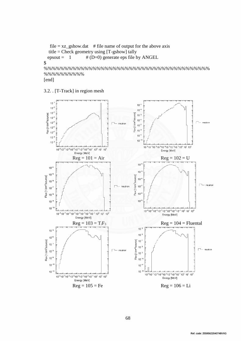
Ref. code: 25595622040748VXGRef. code: 25595622040748VXG
68
file = xz_gshow.dat # file name of output for the above axis
title = Check geometry using [T-gshow] tally
epsout = 1 # (D=0) generate eps file by ANGEL
$
%%%%%%%%%%%%%%%%%%%%%%%%%%%%%%%%%%%%%%%%%
%%%%%%%%%%
[end]
3.2. . [T-Track] in region mesh
Reg = 101 = Air Reg = 102 = U
Reg = 103 = TiF3 Reg = 104 = Fluental
Reg = 105 = Fe Reg = 106 = Li

Ref. code: 25595622040748VXGRef. code: 25595622040748VXG
69
Reg = 107 = Bi Reg = 108 = Pb
Reg = 109 = LiF Reg = 110 = Air

Ref. code: 25595622040748VXGRef. code: 25595622040748VXG
70
Appendix B
Development of BSA
1. Pb as a Multiplier
1.1. Input file
[title]
Example 1: Get started
$ "D" = default value
$ Comments with '$', '#', 'c'
$
%%%%%%%%%%%%%%%%%%%%%%%%%%%%%%%%%%%%%%%%%
%%%%%%%%%%
[parameters] $ Simulation parameters
file(6) = phits.out $ Output filename
maxcas = 1e7 $ Number of events per batch
maxbch = 1 $ Number of batch
imout = 2 $ Option of material representation in [material] 2:MCNP-type
icntl = 0 $ (D=0)Calculation mode: 0=real simulation, 5=no reactions
(void all), 6=source check, 8=check geometry
itall = 1 $ (D=0) Tally ouput after every batch. D=0 not output, D=1
output in same file
$ Cut-off energy
emin(1) = 1.0e-3 $ (D=1.0) cut-off energy for proton (MeV)
emin(2) = 1.e-10 $ (D=1.0) cut-off energy for neutron (MeV)
emin(12) = 1.e-1 # (D=1.d9) cut-off energy of electron (MeV)
emin(13) = 1.e-1 # (D=1.d9) cut-off energy of positron (MeV)
emin(14) = 1.e-3 # (D=1.d9) cut-off energy of photon (MeV)
emin(15) = 2.0e-3 # (D=1.d9) cut-off energy of deuteron (MeV/nucleon)
emin(16) = 3.0e-3 # (D=1.d9) cut-off energy of triton (MeV/nucleon)
emin(17) = 3.0e-3 # (D=1.d9) cut-off energy of 3He (MeV/nucleon)
emin(18) = 4.0e-3 # (D=1.d9) cut-off energy of Alpha (MeV/nucleon)
emin(19) = 1.0e-3 # (D=1.d9) cut-off energy of Heavy Ion (MeV/nucleon)
$ Maximum energy of nulcear data library used
$ By default, PHITS omits electron/positron/photon transport & uses Boltzmann
transport for low-energy neutrons (<20MeV)
dmax(2) = 20.0 $ Neutron
dmax(12) = 1.0 $ Electron
dmax(13) = 1.0 $ positron
dmax(14) = 1.0 $ photon
$ Option for nuclear reactions

Ref. code: 25595622040748VXGRef. code: 25595622040748VXG
71
e-mode = 1 $ (D=0) Option for event-generator: 0=OFF, 1=ON
igamma = 1 $ (D=0) Option for gamma decay for residual nuclei: 0=no
decay, 1=use 'trxcrd.dat', 2=EBITIM model, 3=EBITIM+isomer production
ipnint = 1 $ (D=0) Option for photonuclear reaction: 0=OFF, 1=ON
file(7) = data/xsdir.jnd $ Cross section data library for low energy neutrons
file(14)= data/trxcrd.dat $ Cross section data library for photon emission from
residual nuclei
$ Option for charged particle transport
nedisp = 1 $ (D=0) Energy straggling: 0=OFF, 1=Landau-Vavilov
nspred = 2 $ (D=0) Angle straggling: 0=OFF, 2=Moliere First Coulomb
diffusion
itstep = 1 $ (D=0) Option for timing tally "correct" curvature for
momentum changing trajectory e.g. in magnetic field
$
%%%%%%%%%%%%%%%%%%%%%%%%%%%%%%%%%%%%%%%%%
%%%%%%%%%%
[source]
s-type = 1 % Source type: 1=cylinder, 2=rectangular, 9=spherical
proj = 2112 % Projectile: 2112=neutron
dir = 1 % Initial direction relative to positive-z axis: dir=cosine
e0 = 2.45 % Initial energy (MeV)
x0 = 0
y0 = 0
z0 = 0. % zmin (cm)
z1 = 0. % zmax: z1=z0 circle plan source
r0 = 1.7 % radius of the cylindrical source
$
%%%%%%%%%%%%%%%%%%%%%%%%%%%%%%%%%%%%%%%%%
%%%%%%%%%%
[material]
$ Material composition info: nuclei & density
$ Density can be defined in [cell], then in [material] you only need to define material
compositions
$ i.e. weight fractions, if density is defined in g/cm^3, or atomic fractions if density in
10^24 atoms/cm^3
$ Library number and data class in "data/xsdir.jnd"
MAT[1] $ Lead, den = 11.35 g/cc
82204.50c -0.01378
82206.50c -0.23955
82207.50c -0.22074
82208.50c -0.52592

Ref. code: 25595622040748VXGRef. code: 25595622040748VXG
72
MAT[2] $ Dry air, den=0.001205g/cc
6000.50c -0.000124
7014.50c -0.752291
7015.50c -0.002977
8016.50c -0.231781
18040.50c -0.012827
$
%%%%%%%%%%%%%%%%%%%%%%%%%%%%%%%%%%%%%%%%%
%%%%%%%%%
[mat name color]
mat name size color
0 void 1 white
1 Pb 1 camel
2 air 1 blue
$
%%%%%%%%%%%%%%%%%%%%%%%%%%%%%%%%%%%%%%%%%
%%%%%%%%%%
[ S u r f a c e ]
10 so 500.
11 cz 20. $ 20 cm radius of Pb and 4 cm thickness
12 pz 0.
13 pz 4.
14 sph 0 0 0 1 $ Air 1 cm radius, detector
$
%%%%%%%%%%%%%%%%%%%%%%%%%%%%%%%%%%%%%%%%%
%%%%%%%%%%
[cell]
$ If density is positive: unit 10^24 atoms/cm^3 (= atoms/barn/cm)
$ If density is negative: unit g/cm^3
$id mat den surface
100 -1 10
101 1 -11.35 -11 12 -13
102 2 -0.001205 -14 trcl=(0 0 5)
110 0 -10 #101 #102 $ working area
$
%%%%%%%%%%%%%%%%%%%%%%%%%%%%%%%%%%%%%%%%%
%%%%%%%%%%
[volume]
reg vol
101 5024. $ cell 1
102 4.19
Ref. code: 25595622040748VXGRef. code: 25595622040748VXG
73
$
%%%%%%%%%%%%%%%%%%%%%%%%%%%%%%%%%%%%%%%%%
%%%%%%%%%%
[ T - product ]off $ Check product-eng
mesh = reg
reg = {101-105}
e-type = 3 $ (=3) log scale
ne = 50
emin = 1.e-8
emax = 100. $ MeV
mother = all
part = Neutron Photon
unit = 1 $ 1/source
axis = eng
file = product-eng.dat
gshow = 3
epsout = 1
resol = 1
[t-track] off $xy: check geometry
$Region crossing tally
mesh = xyz
z-type = 1
nz = 3
-5 0 10 20 30 45
x-type = 2
nx = 100
xmin = -15
xmax = 15
y-type = 2
ny = 100
ymin = -15
ymax = 15
e-type = 3 $ All energies
ne = 1
emin = 1e-8
emax = 1e2 $ MeV
Ref. code: 25595622040748VXGRef. code: 25595622040748VXG
74
part = Neutron Photon $ 2112=neutron 22=photon
unit = 1 $ 1/cm^2/source
axis = xy
file = track-xy.dat $ all particles in one diagram
gshow = 3 $ 2: region boundary & material name; 3: region
boundary and name
epsout = 1
resol = 1
$
%%%%%%%%%%%%%%%%%%%%%%%%%%%%%%%%%%%%%%%%%
%%%%%%%%%%
[t-track] off $yz: check geometry
$Region crossing tally
mesh = xyz
x-type = 1
nx = 3
-30 -10 +10 +30
y-type = 2
ny = 100
ymin = -30
ymax = 30
z-type = 2
nz = 100
zmin = -5
zmax = 60
e-type = 3 $ All energies
ne = 1
emin = 1e-8
emax = 1e2 $ MeV
part = Neutron Photon $ 2112=neutron 22=photon
unit = 1 $ 1/cm^2/source
axis = yz
file = track-yz.dat $ all particles in one diagram
gshow = 3 $ 2: region boundary & material name; 3: region
boundary and region name
epsout = 1
resol = 1
Ref. code: 25595622040748VXGRef. code: 25595622040748VXG
75
$
%%%%%%%%%%%%%%%%%%%%%%%%%%%%%%%%%%%%%%%%%
%%%%%%%%%%
[T-track] $ Tally particle energies in detectors
$ Region crossing tally
mesh = reg
reg = {101-102}
e-type = 3 $ (=3) log scale
ne = 50
emin = 1.e-8
emax = 100. $ MeV
part = Neutron $ 2112=neutron, 22=photon, 2212=proton
unit = 1 $ 1/cm^2/source
axis = eng
file = track-reg-eng-DDMul4.dat $ all particles in one diagram
gshow = 3 $ 2: region boundary & material name; 3: region
boundary and name
epsout = 1
resol = 1
$
%%%%%%%%%%%%%%%%%%%%%%%%%%%%%%%%%%%%%%%%%
%%%%%%%%%%
[ T - product ] off $ Check source xy
mesh = xyz
z-type = 1
nz = 3
-5 0 10 20 30 45
x-type = 2
nx = 100
xmin = -30
xmax = 30
y-type = 2
ny = 100
ymin = -30
ymax = 30
e-type = 3 $ All energies
ne = 1
Ref. code: 25595622040748VXGRef. code: 25595622040748VXG
76
emin = 1.e-8
emax = 100.0 $ MeV
part = neutron
unit = 1 $ (=1) 1/source, (=2) 1/cm^3/source
output = source
axis = xy
file = source-xy.dat
gshow = 3
epsout = 1
resol = 1
[ T - Gshow ] off
mesh = xyz # mesh type is xyz scoring mesh
x-type = 2 # x-mesh is linear given by xmin, xmax and nx
nx = 50 # number of x-mesh points
xmin = -25. # minimum value of x-mesh points
xmax = 25. # maximum value of x-mesh points
y-type = 2 # y-mesh is linear given by ymin, ymax and ny
ny = 50 # number of y-mesh points
ymin = -25. # minimum value of y-mesh points
ymax = 25. # maximum value of y-mesh points
z-type = 1 # z-mesh is given by the below data
nz = 1 # number of z-mesh points
0.0 25.0
axis = xy # axis of output
output = 6 # (D=2) 1:bnd, 2:bnd+mat, 3:bnd+num 4:bnd+mat+num
file = xy_gshow.dat # file name of output for the above axis
title = Check geometry using [T-gshow] tally
epsout = 1 # (D=0) generate eps file by ANGEL
[ T - Gshow ] off
mesh = xyz # mesh type is xyz scoring mesh
x-type = 2 # x-mesh is linear given by xmin, xmax and nx
nx = 50 # number of x-mesh points
xmin = -25. # minimum value of x-mesh points
xmax = 25. # maximum value of x-mesh points
y-type = 1 # y-mesh is given by the below data
ny = 1 # number of y-mesh points
-25.0 25.0
z-type = 2 # z-mesh is linear given by zmin, zmax and nz
nz = 50 # number of z-mesh points
zmin = -10. # minimum value of z-mesh points
zmax = 80. # maximum value of z-mesh points
axis = xz # axis of output
output = 6 # (D=2) 1:bnd, 2:bnd+mat, 3:bnd+num 4:bnd+mat+num
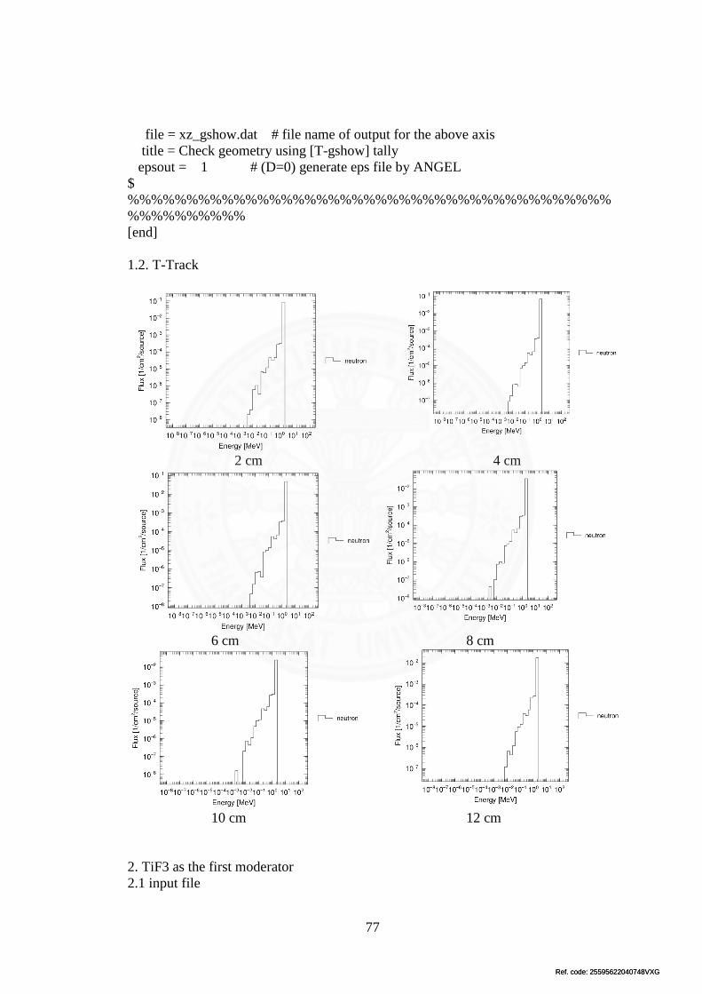
Ref. code: 25595622040748VXGRef. code: 25595622040748VXG
77
file = xz_gshow.dat # file name of output for the above axis
title = Check geometry using [T-gshow] tally
epsout = 1 # (D=0) generate eps file by ANGEL
$
%%%%%%%%%%%%%%%%%%%%%%%%%%%%%%%%%%%%%%%%%
%%%%%%%%%%
[end]
1.2. T-Track
2 cm 4 cm
6 cm 8 cm
10 cm 12 cm
2. TiF3 as the first moderator
2.1 input file

Ref. code: 25595622040748VXGRef. code: 25595622040748VXG
78
[title]
Example 1: Get started
$ "D" = default value
$ Comments with '$', '#', 'c'
$
%%%%%%%%%%%%%%%%%%%%%%%%%%%%%%%%%%%%%%%%%
%%%%%%%%%%
[parameters] $ Simulation parameters
file(6) = phits.out $ Output filename
maxcas = 1e7 $ Number of events per batch
maxbch = 1 $ Number of batch
imout = 2 $ Option of material representation in [material] 2:MCNP-type
icntl = 0 $ (D=0)Calculation mode: 0=real simulation, 5=no reactions
(void all), 6=source check, 8=check geometry
itall = 1 $ (D=0) Tally ouput after every batch. D=0 not output, D=1
output in same file
$ Cut-off energy
emin(1) = 1.0e-3 $ (D=1.0) cut-off energy for proton (MeV)
emin(2) = 1.e-10 $ (D=1.0) cut-off energy for neutron (MeV)
emin(12) = 1.e-1 # (D=1.d9) cut-off energy of electron (MeV)
emin(13) = 1.e-1 # (D=1.d9) cut-off energy of positron (MeV)
emin(14) = 1.e-3 # (D=1.d9) cut-off energy of photon (MeV)
emin(15) = 2.0e-3 # (D=1.d9) cut-off energy of deuteron (MeV/nucleon)
emin(16) = 3.0e-3 # (D=1.d9) cut-off energy of triton (MeV/nucleon)
emin(17) = 3.0e-3 # (D=1.d9) cut-off energy of 3He (MeV/nucleon)
emin(18) = 4.0e-3 # (D=1.d9) cut-off energy of Alpha (MeV/nucleon)
emin(19) = 1.0e-3 # (D=1.d9) cut-off energy of Heavy Ion (MeV/nucleon)
$ Maximum energy of nulcear data library used
$ By default, PHITS omits electron/positron/photon transport & uses Boltzmann
transport for low-energy neutrons (<20MeV)
dmax(2) = 20.0 $ Neutron
dmax(12) = 1.0 $ Electron
dmax(13) = 1.0 $ positron
dmax(14) = 1.0 $ photon
$ Option for nuclear reactions
e-mode = 1 $ (D=0) Option for event-generator: 0=OFF, 1=ON
igamma = 1 $ (D=0) Option for gamma decay for residual nuclei: 0=no
decay, 1=use 'trxcrd.dat', 2=EBITIM model, 3=EBITIM+isomer production
ipnint = 1 $ (D=0) Option for photonuclear reaction: 0=OFF, 1=ON
file(7) = data/xsdir.jnd $ Cross section data library for low energy neutrons
file(14)= data/trxcrd.dat $ Cross section data library for photon emission from
residual nuclei

Ref. code: 25595622040748VXGRef. code: 25595622040748VXG
79
$ Option for charged particle transport
nedisp = 1 $ (D=0) Energy straggling: 0=OFF, 1=Landau-Vavilov
nspred = 2 $ (D=0) Angle straggling: 0=OFF, 2=Moliere First Coulomb
diffusion
itstep = 1 $ (D=0) Option for timing tally "correct" curvature for
momentum changing trajectory e.g. in magnetic field
$
%%%%%%%%%%%%%%%%%%%%%%%%%%%%%%%%%%%%%%%%%
%%%%%%%%%%
[source]
s-type = 1 % Source type: 1=cylinder, 2=rectangular, 9=spherical
proj = 2112 % Projectile: 2112=neutron
dir = 1 % Initial direction relative to positive-z axis: dir=cosine
e0 = 2.45 % Initial energy (MeV)
x0 = 0
y0 = 0
z0 = 0. % zmin (cm)
z1 = 0. % zmax: z1=z0 circle plan source
r0 = 1.7 % radius of the cylindrical source
$
%%%%%%%%%%%%%%%%%%%%%%%%%%%%%%%%%%%%%%%%%
%%%%%%%%%%
[material]
$ Material composition info: nuclei & density
$ Density can be defined in [cell], then in [material] you only need to define material
compositions
$ i.e. weight fractions, if density is defined in g/cm^3, or atomic fractions if density in
10^24 atoms/cm^3
$ Library number and data class in "data/xsdir.jnd"
MAT[1] $ Lead, den = 11.35 g/cc
82204.50c -0.01378
82206.50c -0.23955
82207.50c -0.22074
82208.50c -0.52592
MAT[2] $ Titanium trifluoride, den = 3.4 g/cc
22048.50c -0.336517056
22046.50c -0.037655035
22049.50c -0.024691003
22047.50c -0.033948418
22050.50c -0.023668488
9019.50c -0.54352

Ref. code: 25595622040748VXGRef. code: 25595622040748VXG
80
MAT[3] $ Dry air, den=0.001205g/cc
6000.50c -0.000124
7014.50c -0.752291
7015.50c -0.002977
8016.50c -0.231781
18040.50c -0.012827
$
%%%%%%%%%%%%%%%%%%%%%%%%%%%%%%%%%%%%%%%%%
%%%%%%%%%
[mat name color]
mat name size color
0 void 1 white
1 Pb 1 camel
2 TiF3 1 pink
3 air 1 blue
$
%%%%%%%%%%%%%%%%%%%%%%%%%%%%%%%%%%%%%%%%%
%%%%%%%%%%
[ S u r f a c e ]
10 so 500.
11 cz 20. $ 20 cm radius of Pb and 4 cm thickness
12 pz 0.
13 pz 4.
14 cz 20. $ 20 cm radius of Tif3 and 16 cm thickness
15 pz 4.
16 pz 20.
17 sph 0 0 0 1 $ Air 1 cm radius, detector
$
%%%%%%%%%%%%%%%%%%%%%%%%%%%%%%%%%%%%%%%%%
%%%%%%%%%%
[cell]
$ If density is positive: unit 10^24 atoms/cm^3 (= atoms/barn/cm)
$ If density is negative: unit g/cm^3
$id mat den surface
100 -1 10
101 1 -11.35 -11 12 -13
102 2 -3.4 -14 15 -16
103 3 -0.001205 -17 trcl=(0 0 21)
110 0 -10 #101 #102 #103 $ working area
$
%%%%%%%%%%%%%%%%%%%%%%%%%%%%%%%%%%%%%%%%%
%%%%%%%%%%

Ref. code: 25595622040748VXGRef. code: 25595622040748VXG
81
[volume]
reg vol
101 5024. $ cell 1
102 20096.
103 4.19
$
%%%%%%%%%%%%%%%%%%%%%%%%%%%%%%%%%%%%%%%%%
%%%%%%%%%%
[ T - product ]off $ Check product-eng
mesh = reg
reg = {101-105}
e-type = 3 $ (=3) log scale
ne = 50
emin = 1.e-8
emax = 100. $ MeV
mother = all
part = Neutron Photon
unit = 1 $ 1/source
axis = eng
file = product-eng.dat
gshow = 3
epsout = 1
resol = 1
[t-track] off $xy: check geometry
$Region crossing tally
mesh = xyz
z-type = 1
nz = 3
-5 0 10 20 30 45
x-type = 2
nx = 100
xmin = -15
xmax = 15
y-type = 2
ny = 100
ymin = -15

Ref. code: 25595622040748VXGRef. code: 25595622040748VXG
82
ymax = 15
e-type = 3 $ All energies
ne = 1
emin = 1e-8
emax = 1e2 $ MeV
part = Neutron Photon $ 2112=neutron 22=photon
unit = 1 $ 1/cm^2/source
axis = xy
file = track-xy.dat $ all particles in one diagram
gshow = 3 $ 2: region boundary & material name; 3: region
boundary and name
epsout = 1
resol = 1
$
%%%%%%%%%%%%%%%%%%%%%%%%%%%%%%%%%%%%%%%%%
%%%%%%%%%%
[t-track] off $yz: check geometry
$Region crossing tally
mesh = xyz
x-type = 1
nx = 3
-30 -10 +10 +30
y-type = 2
ny = 100
ymin = -30
ymax = 30
z-type = 2
nz = 100
zmin = -5
zmax = 60
e-type = 3 $ All energies
ne = 1
emin = 1e-8
emax = 1e2 $ MeV
part = Neutron Photon $ 2112=neutron 22=photon
unit = 1 $ 1/cm^2/source

Ref. code: 25595622040748VXGRef. code: 25595622040748VXG
83
axis = yz
file = track-yz.dat $ all particles in one diagram
gshow = 3 $ 2: region boundary & material name; 3: region
boundary and region name
epsout = 1
resol = 1
$
%%%%%%%%%%%%%%%%%%%%%%%%%%%%%%%%%%%%%%%%%
%%%%%%%%%%
[T-track] $ Tally particle energies in detectors
$ Region crossing tally
mesh = reg
reg = {101-103}
e-type = 3 $ (=3) log scale
ne = 50
emin = 1.e-8
emax = 100. $ MeV
part = Neutron $ 2112=neutron, 22=photon, 2212=proton
unit = 1 $ 1/cm^2/source
axis = eng
file = track-reg-eng-DDmode16.dat $ all particles in one diagram
gshow = 3 $ 2: region boundary & material name; 3: region
boundary and name
epsout = 1
resol = 1
$
%%%%%%%%%%%%%%%%%%%%%%%%%%%%%%%%%%%%%%%%%
%%%%%%%%%%
[ T - product ] off $ Check source xy
mesh = xyz
z-type = 1
nz = 3
-5 0 10 20 30 45
x-type = 2
nx = 100
xmin = -30
xmax = 30
y-type = 2

Ref. code: 25595622040748VXGRef. code: 25595622040748VXG
84
ny = 100
ymin = -30
ymax = 30
e-type = 3 $ All energies
ne = 1
emin = 1.e-8
emax = 100.0 $ MeV
part = neutron
unit = 1 $ (=1) 1/source, (=2) 1/cm^3/source
output = source
axis = xy
file = source-xy.dat
gshow = 3
epsout = 1
resol = 1
[ T - Gshow ] off
mesh = xyz # mesh type is xyz scoring mesh
x-type = 2 # x-mesh is linear given by xmin, xmax and nx
nx = 50 # number of x-mesh points
xmin = -25. # minimum value of x-mesh points
xmax = 25. # maximum value of x-mesh points
y-type = 2 # y-mesh is linear given by ymin, ymax and ny
ny = 50 # number of y-mesh points
ymin = -25. # minimum value of y-mesh points
ymax = 25. # maximum value of y-mesh points
z-type = 1 # z-mesh is given by the below data
nz = 1 # number of z-mesh points
0.0 25.0
axis = xy # axis of output
output = 6 # (D=2) 1:bnd, 2:bnd+mat, 3:bnd+num 4:bnd+mat+num
file = xy_gshow.dat # file name of output for the above axis
title = Check geometry using [T-gshow] tally
epsout = 1 # (D=0) generate eps file by ANGEL
[ T - Gshow ] off
mesh = xyz # mesh type is xyz scoring mesh
x-type = 2 # x-mesh is linear given by xmin, xmax and nx
nx = 50 # number of x-mesh points
xmin = -25. # minimum value of x-mesh points
xmax = 25. # maximum value of x-mesh points
y-type = 1 # y-mesh is given by the below data
ny = 1 # number of y-mesh points
-25.0 25.0

Ref. code: 25595622040748VXGRef. code: 25595622040748VXG
85
z-type = 2 # z-mesh is linear given by zmin, zmax and nz
nz = 50 # number of z-mesh points
zmin = -10. # minimum value of z-mesh points
zmax = 80. # maximum value of z-mesh points
axis = xz # axis of output
output = 6 # (D=2) 1:bnd, 2:bnd+mat, 3:bnd+num 4:bnd+mat+num
file = xz_gshow.dat # file name of output for the above axis
title = Check geometry using [T-gshow] tally
epsout = 1 # (D=0) generate eps file by ANGEL
$
%%%%%%%%%%%%%%%%%%%%%%%%%%%%%%%%%%%%%%%%%
%%%%%%%%%%
[end]
2.2. [t-track]
4 cm 8 cm
12 cm 16 cm
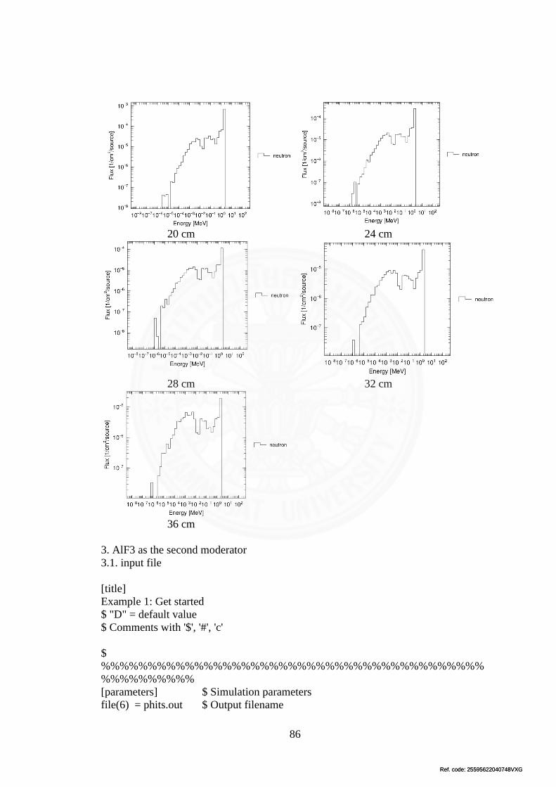
Ref. code: 25595622040748VXGRef. code: 25595622040748VXG
86
20 cm 24 cm
28 cm 32 cm
36 cm
3. AlF3 as the second moderator
3.1. input file
[title]
Example 1: Get started
$ "D" = default value
$ Comments with '$', '#', 'c'
$
%%%%%%%%%%%%%%%%%%%%%%%%%%%%%%%%%%%%%%%%%
%%%%%%%%%%
[parameters] $ Simulation parameters
file(6) = phits.out $ Output filename

Ref. code: 25595622040748VXGRef. code: 25595622040748VXG
87
maxcas = 1e7 $ Number of events per batch
maxbch = 1 $ Number of batch
imout = 2 $ Option of material representation in [material] 2:MCNP-type
icntl = 0 $ (D=0)Calculation mode: 0=real simulation, 5=no reactions (void
all), 6=source check, 8=check geometry
itall = 1 $ (D=0) Tally ouput after every batch. D=0 not output, D=1
output in same file
$ Cut-off energy
emin(1) = 1.0e-3 $ (D=1.0) cut-off energy for proton (MeV)
emin(2) = 1.e-10 $ (D=1.0) cut-off energy for neutron (MeV)
emin(12) = 1.e-1 # (D=1.d9) cut-off energy of electron (MeV)
emin(13) = 1.e-1 # (D=1.d9) cut-off energy of positron (MeV)
emin(14) = 1.e-3 # (D=1.d9) cut-off energy of photon (MeV)
emin(15) = 2.0e-3 # (D=1.d9) cut-off energy of deuteron (MeV/nucleon)
emin(16) = 3.0e-3 # (D=1.d9) cut-off energy of triton (MeV/nucleon)
emin(17) = 3.0e-3 # (D=1.d9) cut-off energy of 3He (MeV/nucleon)
emin(18) = 4.0e-3 # (D=1.d9) cut-off energy of Alpha (MeV/nucleon)
emin(19) = 1.0e-3 # (D=1.d9) cut-off energy of Heavy Ion (MeV/nucleon)
$ Maximum energy of nulcear data library used
$ By default, PHITS omits electron/positron/photon transport & uses Boltzmann
transport for low-energy neutrons (<20MeV)
dmax(2) = 20.0 $ Neutron
dmax(12) = 1.0 $ Electron
dmax(13) = 1.0 $ positron
dmax(14) = 1.0 $ photon
$ Option for nuclear reactions
e-mode = 1 $ (D=0) Option for event-generator: 0=OFF, 1=ON
igamma = 1 $ (D=0) Option for gamma decay for residual nuclei: 0=no
decay, 1=use 'trxcrd.dat', 2=EBITIM model, 3=EBITIM+isomer production
ipnint = 1 $ (D=0) Option for photonuclear reaction: 0=OFF, 1=ON
file(7) = data/xsdir.jnd $ Cross section data library for low energy neutrons
file(14)= data/trxcrd.dat $ Cross section data library for photon emission from
residual nuclei
$ Option for charged particle transport
nedisp = 1 $ (D=0) Energy straggling: 0=OFF, 1=Landau-Vavilov
nspred = 2 $ (D=0) Angle straggling: 0=OFF, 2=Moliere First Coulomb
diffusion
itstep = 1 $ (D=0) Option for timing tally "correct" curvature for
momentum changing trajectory e.g. in magnetic field
$
%%%%%%%%%%%%%%%%%%%%%%%%%%%%%%%%%%%%%%%%%
%%%%%%%%%%

Ref. code: 25595622040748VXGRef. code: 25595622040748VXG
88
[source]
s-type = 1 % Source type: 1=cylinder, 2=rectangular, 9=spherical
proj = 2112 % Projectile: 2112=neutron
dir = 1 % Initial direction relative to positive-z axis: dir=cosine
e0 = 2.45 % Initial energy (MeV)
x0 = 0
y0 = 0
z0 = 0. % zmin (cm)
z1 = 0. % zmax: z1=z0 circle plan source
r0 = 1.7 % radius of the cylindrical source
$
%%%%%%%%%%%%%%%%%%%%%%%%%%%%%%%%%%%%%%%%%
%%%%%%%%%%
[material]
$ Material composition info: nuclei & density
$ Density can be defined in [cell], then in [material] you only need to define material
compositions
$ i.e. weight fractions, if density is defined in g/cm^3, or atomic fractions if density in
10^24 atoms/cm^3
$ Library number and data class in "data/xsdir.jnd"
MAT[1] $ Lead, den = 11.35 g/cc
82204.50c -0.01378
82206.50c -0.23955
82207.50c -0.22074
82208.50c -0.52592
MAT[2] $ Titanium trifluoride, den = 3.4 g/cc
22048.50c -0.336517056
22046.50c -0.037655035
22049.50c -0.024691003
22047.50c -0.033948418
22050.50c -0.023668488
9019.50c -0.54352
MAT[3] $ Aluminium Fluoride, den = 2.88 g/cc
13027.50c -0.32130
9019.50c -0.67870
MAT[4] $ Dry air, den=0.001205g/cc
6000.50c -0.000124
7014.50c -0.752291
7015.50c -0.002977
8016.50c -0.231781
18040.50c -0.012827

Ref. code: 25595622040748VXGRef. code: 25595622040748VXG
89
$
%%%%%%%%%%%%%%%%%%%%%%%%%%%%%%%%%%%%%%%%%
%%%%%%%%%
[mat name color]
mat name size color
0 void 1 white
1 Pb 1 camel
2 TiF3 1 pink
3 AlF3 1 green
4 air 1 blue
$
%%%%%%%%%%%%%%%%%%%%%%%%%%%%%%%%%%%%%%%%%
%%%%%%%%%%
[ S u r f a c e ]
10 so 500.
11 cz 20. $ 20 cm radius of Pb and 4 cm thickness
12 pz 0.
13 pz 4.
14 cz 20. $ 20 cm radius of Tif3 and 16 cm thickness
15 pz 4.
16 pz 20.
17 cz 20. $ 20 cm radius of AlF3 and 60 cm thickness
18 pz 20.
19 pz 80.
20 sph 0 0 0 1 $ Air 1 cm radius, detector
$
%%%%%%%%%%%%%%%%%%%%%%%%%%%%%%%%%%%%%%%%%
%%%%%%%%%%
[cell]
$ If density is positive: unit 10^24 atoms/cm^3 (= atoms/barn/cm)
$ If density is negative: unit g/cm^3
$id mat den surface
100 -1 10
101 1 -11.35 -11 12 -13
102 2 -3.4 -14 15 -16
103 3 -2.88 -17 18 -19
104 4 -0.001205 -20 trcl=(0 0 81)
110 0 -10 #101 #102 #103 #104 $ working area
$
%%%%%%%%%%%%%%%%%%%%%%%%%%%%%%%%%%%%%%%%%
%%%%%%%%%%
[volume]
Ref. code: 25595622040748VXGRef. code: 25595622040748VXG
90
reg vol
101 5024. $ cell 1
102 20096.
103 75360.
104 4.19
$
%%%%%%%%%%%%%%%%%%%%%%%%%%%%%%%%%%%%%%%%%
%%%%%%%%%%
[ T - product ]off $ Check product-eng
mesh = reg
reg = {101-105}
e-type = 3 $ (=3) log scale
ne = 50
emin = 1.e-8
emax = 100. $ MeV
mother = all
part = Neutron Photon
unit = 1 $ 1/source
axis = eng
file = product-eng.dat
gshow = 3
epsout = 1
resol = 1
[t-track] off $xy: check geometry
$Region crossing tally
mesh = xyz
z-type = 1
nz = 3
-5 0 10 20 30 45
x-type = 2
nx = 100
xmin = -15
xmax = 15
y-type = 2
ny = 100
ymin = -15

Ref. code: 25595622040748VXGRef. code: 25595622040748VXG
91
ymax = 15
e-type = 3 $ All energies
ne = 1
emin = 1e-8
emax = 1e2 $ MeV
part = Neutron Photon $ 2112=neutron 22=photon
unit = 1 $ 1/cm^2/source
axis = xy
file = track-xy.dat $ all particles in one diagram
gshow = 3 $ 2: region boundary & material name; 3: region
boundary and name
epsout = 1
resol = 1
$
%%%%%%%%%%%%%%%%%%%%%%%%%%%%%%%%%%%%%%%%%
%%%%%%%%%%
[t-track] off $yz: check geometry
$Region crossing tally
mesh = xyz
x-type = 1
nx = 3
-30 -10 +10 +30
y-type = 2
ny = 100
ymin = -30
ymax = 30
z-type = 2
nz = 100
zmin = -5
zmax = 60
e-type = 3 $ All energies
ne = 1
emin = 1e-8
emax = 1e2 $ MeV
part = Neutron Photon $ 2112=neutron 22=photon
unit = 1 $ 1/cm^2/source

Ref. code: 25595622040748VXGRef. code: 25595622040748VXG
92
axis = yz
file = track-yz.dat $ all particles in one diagram
gshow = 3 $ 2: region boundary & material name; 3: region
boundary and region name
epsout = 1
resol = 1
$
%%%%%%%%%%%%%%%%%%%%%%%%%%%%%%%%%%%%%%%%%
%%%%%%%%%%
[T-track] $ Tally particle energies in detectors
$ Region crossing tally
mesh = reg
reg = {101-104}
e-type = 3 $ (=3) log scale
ne = 50
emin = 1.e-8
emax = 100. $ MeV
part = Neutron $ 2112=neutron, 22=photon, 2212=proton
unit = 1 $ 1/cm^2/source
axis = eng
file = track-reg-eng-DD2mode60.dat $ all particles in one diagram
gshow = 3 $ 2: region boundary & material name; 3: region
boundary and name
epsout = 1
resol = 1
$
%%%%%%%%%%%%%%%%%%%%%%%%%%%%%%%%%%%%%%%%%
%%%%%%%%%%
[ T - product ] off $ Check source xy
mesh = xyz
z-type = 1
nz = 3
-5 0 10 20 30 45
x-type = 2
nx = 100
xmin = -30
xmax = 30
y-type = 2

Ref. code: 25595622040748VXGRef. code: 25595622040748VXG
93
ny = 100
ymin = -30
ymax = 30
e-type = 3 $ All energies
ne = 1
emin = 1.e-8
emax = 100.0 $ MeV
part = neutron
unit = 1 $ (=1) 1/source, (=2) 1/cm^3/source
output = source
axis = xy
file = source-xy.dat
gshow = 3
epsout = 1
resol = 1
[ T - Gshow ] off
mesh = xyz # mesh type is xyz scoring mesh
x-type = 2 # x-mesh is linear given by xmin, xmax and nx
nx = 50 # number of x-mesh points
xmin = -25. # minimum value of x-mesh points
xmax = 25. # maximum value of x-mesh points
y-type = 2 # y-mesh is linear given by ymin, ymax and ny
ny = 50 # number of y-mesh points
ymin = -25. # minimum value of y-mesh points
ymax = 25. # maximum value of y-mesh points
z-type = 1 # z-mesh is given by the below data
nz = 1 # number of z-mesh points
0.0 25.0
axis = xy # axis of output
output = 6 # (D=2) 1:bnd, 2:bnd+mat, 3:bnd+num 4:bnd+mat+num
file = xy_gshow.dat # file name of output for the above axis
title = Check geometry using [T-gshow] tally
epsout = 1 # (D=0) generate eps file by ANGEL
[ T - Gshow ] off
mesh = xyz # mesh type is xyz scoring mesh
x-type = 2 # x-mesh is linear given by xmin, xmax and nx
nx = 50 # number of x-mesh points
xmin = -25. # minimum value of x-mesh points
xmax = 25. # maximum value of x-mesh points
y-type = 1 # y-mesh is given by the below data
ny = 1 # number of y-mesh points
-25.0 25.0

Ref. code: 25595622040748VXGRef. code: 25595622040748VXG
94
z-type = 2 # z-mesh is linear given by zmin, zmax and nz
nz = 50 # number of z-mesh points
zmin = -10. # minimum value of z-mesh points
zmax = 80. # maximum value of z-mesh points
axis = xz # axis of output
output = 6 # (D=2) 1:bnd, 2:bnd+mat, 3:bnd+num 4:bnd+mat+num
file = xz_gshow.dat # file name of output for the above axis
title = Check geometry using [T-gshow] tally
epsout = 1 # (D=0) generate eps file by ANGEL
$
%%%%%%%%%%%%%%%%%%%%%%%%%%%%%%%%%%%%%%%%%
%%%%%%%%%%
[end]
3.2. T-Track
4 cm 36 cm
50 cm 55 cm

Ref. code: 25595622040748VXGRef. code: 25595622040748VXG
95
60 cm 65 cm
4. Al2O3 as a reflector
4.1 input file
[title]
Example 1: Get started
$ "D" = default value
$ Comments with '$', '#', 'c'
$
%%%%%%%%%%%%%%%%%%%%%%%%%%%%%%%%%%%%%%%%%
%%%%%%%%%%
[parameters] $ Simulation parameters
file(6) = phits.out $ Output filename
maxcas = 1e7 $ Number of events per batch
maxbch = 1 $ Number of batch
imout = 2 $ Option of material representation in [material] 2:MCNP-type
icntl = 0 $ (D=0)Calculation mode: 0=real simulation, 5=no reactions (void
all), 6=source check, 8=check geometry
itall = 1 $ (D=0) Tally ouput after every batch. D=0 not output, D=1
output in same file
$ Cut-off energy
emin(1) = 1.0e-3 $ (D=1.0) cut-off energy for proton (MeV)
emin(2) = 1.e-10 $ (D=1.0) cut-off energy for neutron (MeV)
emin(12) = 1.e-1 # (D=1.d9) cut-off energy of electron (MeV)
emin(13) = 1.e-1 # (D=1.d9) cut-off energy of positron (MeV)
emin(14) = 1.e-3 # (D=1.d9) cut-off energy of photon (MeV)
emin(15) = 2.0e-3 # (D=1.d9) cut-off energy of deuteron (MeV/nucleon)
emin(16) = 3.0e-3 # (D=1.d9) cut-off energy of triton (MeV/nucleon)
emin(17) = 3.0e-3 # (D=1.d9) cut-off energy of 3He (MeV/nucleon)
emin(18) = 4.0e-3 # (D=1.d9) cut-off energy of Alpha (MeV/nucleon)
emin(19) = 1.0e-3 # (D=1.d9) cut-off energy of Heavy Ion (MeV/nucleon)
$ Maximum energy of nulcear data library used
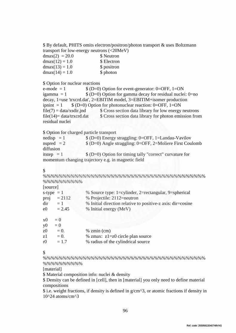
Ref. code: 25595622040748VXGRef. code: 25595622040748VXG
96
$ By default, PHITS omits electron/positron/photon transport & uses Boltzmann
transport for low-energy neutrons (<20MeV)
dmax(2) = 20.0 $ Neutron
dmax(12) = 1.0 $ Electron
dmax(13) = 1.0 $ positron
dmax(14) = 1.0 $ photon
$ Option for nuclear reactions
e-mode = 1 $ (D=0) Option for event-generator: 0=OFF, 1=ON
igamma = 1 $ (D=0) Option for gamma decay for residual nuclei: 0=no
decay, 1=use 'trxcrd.dat', 2=EBITIM model, 3=EBITIM+isomer production
ipnint = 1 $ (D=0) Option for photonuclear reaction: 0=OFF, 1=ON
file(7) = data/xsdir.jnd $ Cross section data library for low energy neutrons
file(14)= data/trxcrd.dat $ Cross section data library for photon emission from
residual nuclei
$ Option for charged particle transport
nedisp = 1 $ (D=0) Energy straggling: 0=OFF, 1=Landau-Vavilov
nspred = 2 $ (D=0) Angle straggling: 0=OFF, 2=Moliere First Coulomb
diffusion
itstep = 1 $ (D=0) Option for timing tally "correct" curvature for
momentum changing trajectory e.g. in magnetic field
$
%%%%%%%%%%%%%%%%%%%%%%%%%%%%%%%%%%%%%%%%%
%%%%%%%%%%
[source]
s-type = 1 % Source type: 1=cylinder, 2=rectangular, 9=spherical
proj = 2112 % Projectile: 2112=neutron
dir = 1 % Initial direction relative to positive-z axis: dir=cosine
e0 = 2.45 % Initial energy (MeV)
x0 = 0
y0 = 0
z0 = 0. % zmin (cm)
z1 = 0. % zmax: z1=z0 circle plan source
r0 = 1.7 % radius of the cylindrical source
$
%%%%%%%%%%%%%%%%%%%%%%%%%%%%%%%%%%%%%%%%%
%%%%%%%%%%
[material]
$ Material composition info: nuclei & density
$ Density can be defined in [cell], then in [material] you only need to define material
compositions
$ i.e. weight fractions, if density is defined in g/cm^3, or atomic fractions if density in
10^24 atoms/cm^3

Ref. code: 25595622040748VXGRef. code: 25595622040748VXG
97
$ Library number and data class in "data/xsdir.jnd"
MAT[1] $ Lead, den = 11.35 g/cc
82204.50c -0.01378
82206.50c -0.23955
82207.50c -0.22074
82208.50c -0.52592
MAT[2] $ Titanium trifluoride, den = 3.4 g/cc
22048.50c -0.336517056
22046.50c -0.037655035
22049.50c -0.024691003
22047.50c -0.033948418
22050.50c -0.023668488
9019.50c -0.54352
MAT[3] $ Aluminium Fluoride, den = 2.88 g/cc
13027.50c -0.32130
9019.50c -0.67870
MAT[4] $ Aluminum Oxide, den = 3.97 g/cc
8016.50c -0.470749
13027.50c -0.52925
MAT[5] $ Dry air, den=0.001205g/cc
6000.50c -0.000124
7014.50c -0.752291
7015.50c -0.002977
8016.50c -0.231781
18040.50c -0.012827
$
%%%%%%%%%%%%%%%%%%%%%%%%%%%%%%%%%%%%%%%%%
%%%%%%%%%
[mat name color]
mat name size color
0 void 1 white
1 Pb 1 camel
2 TiF3 1 pink
3 AlF3 1 green
4 Al2O3 1 yellow
5 air 1 blue
$
%%%%%%%%%%%%%%%%%%%%%%%%%%%%%%%%%%%%%%%%%
%%%%%%%%%%
[ S u r f a c e ]

Ref. code: 25595622040748VXGRef. code: 25595622040748VXG
98
10 so 500.
11 cz 20. $ 20 cm radius of Pb and 4 cm thickness
12 pz 0.
13 pz 4.
14 cz 20. $ 20 cm radius of Tif3 and 16 cm thickness
15 pz 4.
16 pz 20.
17 cz 20. $ 20 cm radius of AlF3 and 60 cm thickness
18 pz 20.
19 pz 80.
20 cz 30. $ 30 cm radius of Al2O3 and 80 cm as a reflector
21 pz 0.
22 pz 80.
23 sph 0 0 0 1 $ Air 1 cm radius, detector
$
%%%%%%%%%%%%%%%%%%%%%%%%%%%%%%%%%%%%%%%%%
%%%%%%%%%%
[cell]
$ If density is positive: unit 10^24 atoms/cm^3 (= atoms/barn/cm)
$ If density is negative: unit g/cm^3
$id mat den surface
100 -1 10
101 1 -11.35 -11 12 -13
102 2 -3.4 -14 15 -16
103 3 -2.88 -17 18 -19
104 4 -3.97 -20 21 -22 #101 #102 #103
105 5 -0.001205 -23 trcl=(0 0 81)
110 0 -10 #101 #102 #103 #104 #105 $ working area
$
%%%%%%%%%%%%%%%%%%%%%%%%%%%%%%%%%%%%%%%%%
%%%%%%%%%%
[volume]
reg vol
101 5024. $ cell 1
102 20096.
103 75360.
104 125600.
105 4.19
$
%%%%%%%%%%%%%%%%%%%%%%%%%%%%%%%%%%%%%%%%%
%%%%%%%%%%
[ T - product ]off $ Check product-eng

Ref. code: 25595622040748VXGRef. code: 25595622040748VXG
99
mesh = reg
reg = {101-105}
e-type = 3 $ (=3) log scale
ne = 50
emin = 1.e-8
emax = 100. $ MeV
mother = all
part = Neutron Photon
unit = 1 $ 1/source
axis = eng
file = product-eng.dat
gshow = 3
epsout = 1
resol = 1
[t-track] off $xy: check geometry
$Region crossing tally
mesh = xyz
z-type = 1
nz = 3
-5 0 10 20 30 45
x-type = 2
nx = 100
xmin = -15
xmax = 15
y-type = 2
ny = 100
ymin = -15
ymax = 15
e-type = 3 $ All energies
ne = 1
emin = 1e-8
emax = 1e2 $ MeV
part = Neutron Photon $ 2112=neutron 22=photon
unit = 1 $ 1/cm^2/source
axis = xy

Ref. code: 25595622040748VXGRef. code: 25595622040748VXG
100
file = track-xy.dat $ all particles in one diagram
gshow = 3 $ 2: region boundary & material name; 3: region
boundary and name
epsout = 1
resol = 1
$
%%%%%%%%%%%%%%%%%%%%%%%%%%%%%%%%%%%%%%%%%
%%%%%%%%%%
[t-track] off $yz: check geometry
$Region crossing tally
mesh = xyz
x-type = 1
nx = 3
-30 -10 +10 +30
y-type = 2
ny = 100
ymin = -30
ymax = 30
z-type = 2
nz = 100
zmin = -5
zmax = 60
e-type = 3 $ All energies
ne = 1
emin = 1e-8
emax = 1e2 $ MeV
part = Neutron Photon $ 2112=neutron 22=photon
unit = 1 $ 1/cm^2/source
axis = yz
file = track-yz.dat $ all particles in one diagram
gshow = 3 $ 2: region boundary & material name; 3: region
boundary and region name
epsout = 1
resol = 1
$
%%%%%%%%%%%%%%%%%%%%%%%%%%%%%%%%%%%%%%%%%
%%%%%%%%%%
[T-track] $ Tally particle energies in detectors

Ref. code: 25595622040748VXGRef. code: 25595622040748VXG
101
$ Region crossing tally
mesh = reg
reg = {101-105}
e-type = 3 $ (=3) log scale
ne = 50
emin = 1.e-8
emax = 100. $ MeV
part = Neutron $ 2112=neutron, 22=photon, 2212=proton
unit = 1 $ 1/cm^2/source
axis = eng
file = track-reg-eng-DD2ref30o.dat $ all particles in one diagram
gshow = 3 $ 2: region boundary & material name; 3: region
boundary and name
epsout = 1
resol = 1
$
%%%%%%%%%%%%%%%%%%%%%%%%%%%%%%%%%%%%%%%%%
%%%%%%%%%%
[ T - product ] off $ Check source xy
mesh = xyz
z-type = 1
nz = 3
-5 0 10 20 30 45
x-type = 2
nx = 100
xmin = -30
xmax = 30
y-type = 2
ny = 100
ymin = -30
ymax = 30
e-type = 3 $ All energies
ne = 1
emin = 1.e-8
emax = 100.0 $ MeV
part = neutron
unit = 1 $ (=1) 1/source, (=2) 1/cm^3/source

Ref. code: 25595622040748VXGRef. code: 25595622040748VXG
102
output = source
axis = xy
file = source-xy.dat
gshow = 3
epsout = 1
resol = 1
[ T - Gshow ] off
mesh = xyz # mesh type is xyz scoring mesh
x-type = 2 # x-mesh is linear given by xmin, xmax and nx
nx = 50 # number of x-mesh points
xmin = -25. # minimum value of x-mesh points
xmax = 25. # maximum value of x-mesh points
y-type = 2 # y-mesh is linear given by ymin, ymax and ny
ny = 50 # number of y-mesh points
ymin = -25. # minimum value of y-mesh points
ymax = 25. # maximum value of y-mesh points
z-type = 1 # z-mesh is given by the below data
nz = 1 # number of z-mesh points
0.0 25.0
axis = xy # axis of output
output = 6 # (D=2) 1:bnd, 2:bnd+mat, 3:bnd+num 4:bnd+mat+num
file = xy_gshow.dat # file name of output for the above axis
title = Check geometry using [T-gshow] tally
epsout = 1 # (D=0) generate eps file by ANGEL
[ T - Gshow ] off
mesh = xyz # mesh type is xyz scoring mesh
x-type = 2 # x-mesh is linear given by xmin, xmax and nx
nx = 50 # number of x-mesh points
xmin = -25. # minimum value of x-mesh points
xmax = 25. # maximum value of x-mesh points
y-type = 1 # y-mesh is given by the below data
ny = 1 # number of y-mesh points
-25.0 25.0
z-type = 2 # z-mesh is linear given by zmin, zmax and nz
nz = 50 # number of z-mesh points
zmin = -10. # minimum value of z-mesh points
zmax = 80. # maximum value of z-mesh points
axis = xz # axis of output
output = 6 # (D=2) 1:bnd, 2:bnd+mat, 3:bnd+num 4:bnd+mat+num
file = xz_gshow.dat # file name of output for the above axis
title = Check geometry using [T-gshow] tally
epsout = 1 # (D=0) generate eps file by ANGEL

Ref. code: 25595622040748VXGRef. code: 25595622040748VXG
103
$
%%%%%%%%%%%%%%%%%%%%%%%%%%%%%%%%%%%%%%%%%
%%%%%%%%%%
[end]
4.2 [t-track]
25 cm 30 cm
35 cm
5. Li as the thermal neutron filter
5.1 input file
[title]
Example 1: Get started
$ "D" = default value
$ Comments with '$', '#', 'c'
$
%%%%%%%%%%%%%%%%%%%%%%%%%%%%%%%%%%%%%%%%%
%%%%%%%%%%
[parameters] $ Simulation parameters
file(6) = phits.out $ Output filename
maxcas = 1e8 $ Number of events per batch
maxbch = 1 $ Number of batch
imout = 2 $ Option of material representation in [material] 2:MCNP-type

Ref. code: 25595622040748VXGRef. code: 25595622040748VXG
104
icntl = 0 $ (D=0)Calculation mode: 0=real simulation, 5=no reactions (void
all), 6=source check, 8=check geometry
itall = 1 $ (D=0) Tally ouput after every batch. D=0 not output, D=1
output in same file
$ Cut-off energy
emin(1) = 1.0e-3 $ (D=1.0) cut-off energy for proton (MeV)
emin(2) = 1.e-10 $ (D=1.0) cut-off energy for neutron (MeV)
emin(12) = 1.e-1 # (D=1.d9) cut-off energy of electron (MeV)
emin(13) = 1.e-1 # (D=1.d9) cut-off energy of positron (MeV)
emin(14) = 1.e-3 # (D=1.d9) cut-off energy of photon (MeV)
emin(15) = 2.0e-3 # (D=1.d9) cut-off energy of deuteron (MeV/nucleon)
emin(16) = 3.0e-3 # (D=1.d9) cut-off energy of triton (MeV/nucleon)
emin(17) = 3.0e-3 # (D=1.d9) cut-off energy of 3He (MeV/nucleon)
emin(18) = 4.0e-3 # (D=1.d9) cut-off energy of Alpha (MeV/nucleon)
emin(19) = 1.0e-3 # (D=1.d9) cut-off energy of Heavy Ion (MeV/nucleon)
$ Maximum energy of nulcear data library used
$ By default, PHITS omits electron/positron/photon transport & uses Boltzmann
transport for low-energy neutrons (<20MeV)
dmax(2) = 20.0 $ Neutron
dmax(12) = 1.0 $ Electron
dmax(13) = 1.0 $ positron
dmax(14) = 1.0 $ photon
$ Option for nuclear reactions
e-mode = 1 $ (D=0) Option for event-generator: 0=OFF, 1=ON
igamma = 1 $ (D=0) Option for gamma decay for residual nuclei: 0=no
decay, 1=use 'trxcrd.dat', 2=EBITIM model, 3=EBITIM+isomer production
ipnint = 1 $ (D=0) Option for photonuclear reaction: 0=OFF, 1=ON
file(7) = data/xsdir.jnd $ Cross section data library for low energy neutrons
file(14)= data/trxcrd.dat $ Cross section data library for photon emission from
residual nuclei
$ Option for charged particle transport
nedisp = 1 $ (D=0) Energy straggling: 0=OFF, 1=Landau-Vavilov
nspred = 2 $ (D=0) Angle straggling: 0=OFF, 2=Moliere First Coulomb
diffusion
itstep = 1 $ (D=0) Option for timing tally "correct" curvature for
momentum changing trajectory e.g. in magnetic field
$
%%%%%%%%%%%%%%%%%%%%%%%%%%%%%%%%%%%%%%%%%
%%%%%%%%%%
[source]
s-type = 1 % Source type: 1=cylinder, 2=rectangular, 9=spherical
proj = 2112 % Projectile: 2112=neutron

Ref. code: 25595622040748VXGRef. code: 25595622040748VXG
105
dir = 1 % Initial direction relative to positive-z axis: dir=cosine
e0 = 2.45 % Initial energy (MeV)
x0 = 0
y0 = 0
z0 = 0. % zmin (cm)
z1 = 0. % zmax: z1=z0 circle plan source
r0 = 1.7 % radius of the cylindrical source
$
%%%%%%%%%%%%%%%%%%%%%%%%%%%%%%%%%%%%%%%%%
%%%%%%%%%%
[material]
$ Material composition info: nuclei & density
$ Density can be defined in [cell], then in [material] you only need to define material
compositions
$ i.e. weight fractions, if density is defined in g/cm^3, or atomic fractions if density in
10^24 atoms/cm^3
$ Library number and data class in "data/xsdir.jnd"
MAT[1] $ Lead, den = 11.35 g/cc
82204.50c -0.01378
82206.50c -0.23955
82207.50c -0.22074
82208.50c -0.52592
MAT[2] $ Titanium trifluoride, den = 3.4 g/cc
22048.50c -0.336517056
22046.50c -0.037655035
22049.50c -0.024691003
22047.50c -0.033948418
22050.50c -0.023668488
9019.50c -0.54352
MAT[3] $ Aluminium Fluoride, den = 2.88 g/cc
13027.50c -0.32130
9019.50c -0.67870
MAT[4] $ Aluminum Oxide, den = 3.97 g/cc
8016.50c -0.470749
13027.50c -0.52925
MAT[5] $ Lithium, den = 0.534 g/cc
3006.50c -0.075
3007.50c -0.925
MAT[6] $ Dry air, den=0.001205g/cc
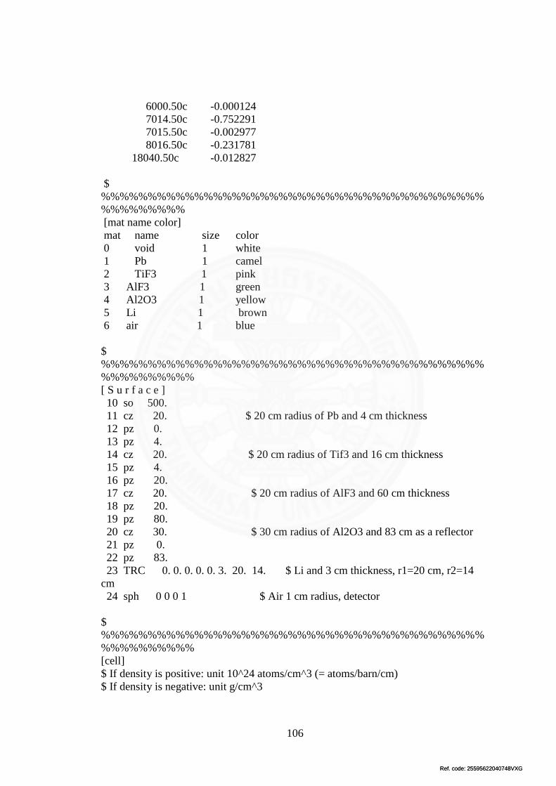
Ref. code: 25595622040748VXGRef. code: 25595622040748VXG
106
6000.50c -0.000124
7014.50c -0.752291
7015.50c -0.002977
8016.50c -0.231781
18040.50c -0.012827
$
%%%%%%%%%%%%%%%%%%%%%%%%%%%%%%%%%%%%%%%%%
%%%%%%%%%
[mat name color]
mat name size color
0 void 1 white
1 Pb 1 camel
2 TiF3 1 pink
3 AlF3 1 green
4 Al2O3 1 yellow
5 Li 1 brown
6 air 1 blue
$
%%%%%%%%%%%%%%%%%%%%%%%%%%%%%%%%%%%%%%%%%
%%%%%%%%%%
[ S u r f a c e ]
10 so 500.
11 cz 20. $ 20 cm radius of Pb and 4 cm thickness
12 pz 0.
13 pz 4.
14 cz 20. $ 20 cm radius of Tif3 and 16 cm thickness
15 pz 4.
16 pz 20.
17 cz 20. $ 20 cm radius of AlF3 and 60 cm thickness
18 pz 20.
19 pz 80.
20 cz 30. $ 30 cm radius of Al2O3 and 83 cm as a reflector
21 pz 0.
22 pz 83.
23 TRC 0. 0. 0. 0. 0. 3. 20. 14. $ Li and 3 cm thickness, r1=20 cm, r2=14
cm
24 sph 0 0 0 1 $ Air 1 cm radius, detector
$
%%%%%%%%%%%%%%%%%%%%%%%%%%%%%%%%%%%%%%%%%
%%%%%%%%%%
[cell]
$ If density is positive: unit 10^24 atoms/cm^3 (= atoms/barn/cm)
$ If density is negative: unit g/cm^3

Ref. code: 25595622040748VXGRef. code: 25595622040748VXG
107
$id mat den surface
100 -1 10
101 1 -11.35 -11 12 -13
102 2 -3.4 -14 15 -16
103 3 -2.88 -17 18 -19
104 4 -3.97 -20 21 -22 #101 #102 #103 #105
105 5 -0.534 -23 trcl=(0 0 80)
106 6 -0.001205 -24 trcl=(0 0 84)
110 0 -10 #101 #102 #103 #104 #105 #106 $ working area
$
%%%%%%%%%%%%%%%%%%%%%%%%%%%%%%%%%%%%%%%%%
%%%%%%%%%%
[volume]
reg vol
101 5024. $ cell 1
102 20096.
103 75360.
104 131325.97
105 2752.03
106 4.19
$
%%%%%%%%%%%%%%%%%%%%%%%%%%%%%%%%%%%%%%%%%
%%%%%%%%%%
[ T - product ]off $ Check product-eng
mesh = reg
reg = {101-105}
e-type = 3 $ (=3) log scale
ne = 50
emin = 1.e-8
emax = 100. $ MeV
mother = all
part = Neutron Photon
unit = 1 $ 1/source
axis = eng
file = product-eng.dat
gshow = 3
epsout = 1
resol = 1
[t-track] off $xy: check geometry

Ref. code: 25595622040748VXGRef. code: 25595622040748VXG
108
$Region crossing tally
mesh = xyz
z-type = 1
nz = 3
-5 0 10 20 30 45
x-type = 2
nx = 100
xmin = -15
xmax = 15
y-type = 2
ny = 100
ymin = -15
ymax = 15
e-type = 3 $ All energies
ne = 1
emin = 1e-8
emax = 1e2 $ MeV
part = Neutron Photon $ 2112=neutron 22=photon
unit = 1 $ 1/cm^2/source
axis = xy
file = track-xy.dat $ all particles in one diagram
gshow = 3 $ 2: region boundary & material name; 3: region
boundary and name
epsout = 1
resol = 1
$
%%%%%%%%%%%%%%%%%%%%%%%%%%%%%%%%%%%%%%%%%
%%%%%%%%%%
[t-track] off $yz: check geometry
$Region crossing tally
mesh = xyz
x-type = 1
nx = 3
-30 -10 +10 +30
y-type = 2
ny = 100

Ref. code: 25595622040748VXGRef. code: 25595622040748VXG
109
ymin = -30
ymax = 30
z-type = 2
nz = 100
zmin = -5
zmax = 60
e-type = 3 $ All energies
ne = 1
emin = 1e-8
emax = 1e2 $ MeV
part = Neutron Photon $ 2112=neutron 22=photon
unit = 1 $ 1/cm^2/source
axis = yz
file = track-yz.dat $ all particles in one diagram
gshow = 3 $ 2: region boundary & material name; 3: region
boundary and region name
epsout = 1
resol = 1
$
%%%%%%%%%%%%%%%%%%%%%%%%%%%%%%%%%%%%%%%%%
%%%%%%%%%%
[T-track] $ Tally particle energies in detectors
$ Region crossing tally
mesh = reg
reg = {101-106}
e-type = 3 $ (=3) log scale
ne = 50
emin = 1.e-8
emax = 100. $ MeV
part = Neutron $ 2112=neutron, 22=photon, 2212=proton
unit = 1 $ 1/cm^2/source
axis = eng
file = track-reg-eng-DD2th3.dat $ all particles in one diagram
gshow = 3 $ 2: region boundary & material name; 3: region
boundary and name
epsout = 1
resol = 1

Ref. code: 25595622040748VXGRef. code: 25595622040748VXG
110
$
%%%%%%%%%%%%%%%%%%%%%%%%%%%%%%%%%%%%%%%%%
%%%%%%%%%%
[ T - product ] off $ Check source xy
mesh = xyz
z-type = 1
nz = 3
-5 0 10 20 30 45
x-type = 2
nx = 100
xmin = -30
xmax = 30
y-type = 2
ny = 100
ymin = -30
ymax = 30
e-type = 3 $ All energies
ne = 1
emin = 1.e-8
emax = 100.0 $ MeV
part = neutron
unit = 1 $ (=1) 1/source, (=2) 1/cm^3/source
output = source
axis = xy
file = source-xy.dat
gshow = 3
epsout = 1
resol = 1
[ T - Gshow ] off
mesh = xyz # mesh type is xyz scoring mesh
x-type = 2 # x-mesh is linear given by xmin, xmax and nx
nx = 50 # number of x-mesh points
xmin = -25. # minimum value of x-mesh points
xmax = 25. # maximum value of x-mesh points
y-type = 2 # y-mesh is linear given by ymin, ymax and ny
ny = 50 # number of y-mesh points
ymin = -25. # minimum value of y-mesh points
ymax = 25. # maximum value of y-mesh points
z-type = 1 # z-mesh is given by the below data

Ref. code: 25595622040748VXGRef. code: 25595622040748VXG
111
nz = 1 # number of z-mesh points
0.0 25.0
axis = xy # axis of output
output = 6 # (D=2) 1:bnd, 2:bnd+mat, 3:bnd+num 4:bnd+mat+num
file = xy_gshow.dat # file name of output for the above axis
title = Check geometry using [T-gshow] tally
epsout = 1 # (D=0) generate eps file by ANGEL
[ T - Gshow ] off
mesh = xyz # mesh type is xyz scoring mesh
x-type = 2 # x-mesh is linear given by xmin, xmax and nx
nx = 50 # number of x-mesh points
xmin = -40. # minimum value of x-mesh points
xmax = 40. # maximum value of x-mesh points
y-type = 1 # y-mesh is given by the below data
ny = 1 # number of y-mesh points
-25.0 25.0
z-type = 2 # z-mesh is linear given by zmin, zmax and nz
nz = 50 # number of z-mesh points
zmin = -10. # minimum value of z-mesh points
zmax = 100. # maximum value of z-mesh points
axis = xz # axis of output
output = 6 # (D=2) 1:bnd, 2:bnd+mat, 3:bnd+num 4:bnd+mat+num
file = xz_gshow.dat # file name of output for the above axis
title = Check geometry using [T-gshow] tally
epsout = 1 # (D=0) generate eps file by ANGEL
$
%%%%%%%%%%%%%%%%%%%%%%%%%%%%%%%%%%%%%%%%%
%%%%%%%%%%
[end]
5.2. [t-track]
1 cm 2 cm

Ref. code: 25595622040748VXGRef. code: 25595622040748VXG
112
3 cm 4 cm