
DESIGN OF ARRAY ANTENNA FOR BODY CENTRIC...
84
DESIGN OF ARRAY ANTENNA FOR BODY CENTRIC COMMUNICATION RAJESHREE A/P VEJASEGARAN RESEARCH REPORT SUBMITTED IN PARTIAL FULFILMENT OF THE REQUIREMENTS FOR THE DEGREE OF MASTER OF ENGINEERING (TELECOMMUNICATIONS) FACULTY OF ENGINEERING UNIVERSITY OF MALAYA KUALA LUMPUR 2017
Transcript of DESIGN OF ARRAY ANTENNA FOR BODY CENTRIC...

DESIGN OF ARRAY ANTENNA FOR BODY CENTRIC
COMMUNICATION
RAJESHREE A/P VEJASEGARAN
RESEARCH REPORT SUBMITTED IN PARTIAL
FULFILMENT
OF THE REQUIREMENTS FOR THE DEGREE
OF MASTER OF ENGINEERING
(TELECOMMUNICATIONS)
FACULTY OF ENGINEERING
UNIVERSITY OF MALAYA
KUALA LUMPUR
2017

ii
UNIVERSITY OF MALAYA
ORIGINAL LITERARY WORK DECLARATION
Name of Candidate: V.RAJESHREE (I.C/Passport No:
Matric No: KGE 150008
Name of Degree: MASTER OF ENGINEERING (TELECOMMUNICATIONS)
Title of Thesis: DESIGN OF ARRAY ANTENNA FOR BODY CENTRIC
COMMUNICATION
Field of Study: ANTENNA AND PROPAGATION
I do solemnly and sincerely declare that:
(1) I am the sole author/writer of this Work;
(2) This Work is original;
(3) Any use of any work in which copyright exists was done by way of fair dealing
and for permitted purposes and any excerpt or extract from, or reference to or
reproduction of any copyright work has been disclosed expressly and sufficiently
and the title of the Work and its authorship have been acknowledged in this Work;
(4) I do not have any actual knowledge nor do I ought reasonably to know that the
making of this work constitutes an infringement of any copyright work;
(5) I hereby assign all and every rights in the copyright to this Work to the University
of Malaya (“UM”), who henceforth shall be owner of the copyright in this Work
and that any reproduction or use in any form or by any means whatsoever is
prohibited without the written consent of UM having been first had and obtained;
(6) I am fully aware that if in the course of making this Work I have infringed any
copyright whether intentionally or otherwise, I may be subject to legal action or
any other action as may be determined by UM.
Candidate’s Signature Date:
Subscribed and solemnly declared before,
Witness’s Signature Date:
Name:
Designation:

iii
ABSTRACT
The main aim of this research is to design single and multi-elements on-body antennas
that operate at 2.4 GHz ISM band. The patch and the ground plane are designed using highly
conductive pure copper while three dielectric materials are used as the substrate for
comparison purposes. The antenna design are simulated using CST Microwave Studio.
Several characteristics of the antenna such as reflection coefficient, bandwidth, VSWR,
efficiency and radiation pattern are evaluated for both free space and on-body application.
The comparison results reveal that the antennas design using RT Duroid 5880 result in low
gain loss. Only small difference in reflection coefficient, S11 and bandwidth is observed for
the array antennas as a consequence of variation in body tissue thickness. The increase in the
fat layer thickness also resulted in a steady increase in gain for all antenna configurations. In
order to minimize the attenuation of antenna performance in close proximity with the human
body, simple gain improvement techniques are utilized. Antenna simulated gain is improved
by 7.2 % for the first design and 8.4 % for the second design of 2x1 array antenna and 4.7 %
for 4x1 array antenna.

iv
ABSTRAK
Tujuan utama penyelidikan ini adalah untuk mereka bentuk antena tunggal dan
berbilang elemen yang diletakkan di atas badan beroperasi pada 2.4 GHz. Patch dan ground
plane direka dengan menggunakan tembaga tulen yang sangat konduktif manakala tiga bahan
dielektrik digunakan sebagai substrat untuk tujuan perbandingan. Simulasi reka bentuk yang
dihasilkan adalah menggunakan Microwave CST Studio. Beberapa ciri antena seperti pekali
pantulan, jalur lebar, VSWR, kecekapan dan corak radiasi dinilai untuk ruang bebas dan
aplikasi di atas badan. Hasil perbandingan menunjukkan bahawa reka bentuk antena yang
menggunakan RT Duroid 5880 menyebabkan kehilangan kuas yang rendah. Hanya
perbezaan kecil dalam koefisien pantulan, S11 dan jalur lebar diperhatikan untuk antena array
akibat variasi dalam ketebalan tisu badan. Peningkatan ketebalan lapisan lemak juga
mengakibatkan peningkatan kuasa dalam semua konfigurasi antenna. Untuk mengurangkan
penguragan prestasi antena dekat dengan tubuh manusia, teknik penambahbaikan kuasa
dilaksanakan. Kuasa antena diperbaiki sebanyak 7.2% untuk reka bentuk pertama dan 8.4%
untuk reka bentuk kedua antena array 2x1 dan 4.7% untuk antena array 4x1.

v
ACKNOWLEDGEMENTS
Firstly, I would like to express my sincere gratitude to my supervisor, Dr. Tarik
bin Abdul Latef. His guidance and knowledge were invaluable to me throughout the
development of this thesis. He also has motivated me to perform to the best of my abilities
and made sure that I understand the concepts throughout the project duration.
I also would like to convey my appreciation to the dedicated staffs of the Deputy
Dean’s office (Postgraduate Studies) of Faculty of Engineering for their administrative
services, information and guidance in the preparation of this research report. Special thanks
are also dedicated to Shah Erawati and Nurhazirah for their guidance.
I could not end this acknowledgement without conveying heartfelt thank you to my
beloved father and sisters for their endless moral and financial support throughout my
academic years and personal growth.

vi
TABLE OF CONTENTS
Page
ORIGINAL LITERARY WORK DECLARATION ii
ABSTRACT iii
ABSTRAK iv
ACKNOWLEDGEMENTS v
TABLE OF CONTENTS vi
LIST OF FIGURES ix
LIST OF TABLES xii
CHAPTER 1: INTRODUCTION
1.1 Background 1
1.2 Problem Statement 2
1.3 Aim and Objectives 3
CHAPTER 2: LITERATURE REVIEW
2.1 Introduction 4
2.2 Frequency Allocation for WBAN 4
2.3 Microstrip Patch Antenna 6
2.4 Feeding Mechanism 7
2.4.1 Transmission Line 8
2.4.2 Inset-Feed 8
2.4.3 Coaxial Feed 9
2.5 Antenna Material Specification 10
2.5.1 Substrate Materials 10
2.5.2 Conductive Materials 11
2.6 Microstrip Antenna Arrays 11
2.6.1 Feeding Networks for Array Antenna 13
2.6.1.1 Corporate Feed Configuration 13

vii
2.7 Study on Biological Tissue Thickness based on Previous Research 14
Works
CHAPTER 3: METHODOLOGY
3.1 Introduction 18
3.2 Project Flow 18
3.3 Design Specification 21
3.3.1 Antenna Material Specification 21
3.3.2 Design Methodology 21
3.4 Antenna Design in Free Space 23
3.4.1 Single Element Design 23
3.4.2 Array Antenna Design 25
3.4.2.1 Array Antenna for FR-4 25
3.4.2.2 Array Antenna for RT Duroid 5880 27
3.4.2.3 Array Antenna for RO 3730 28
3.5 Antenna Design for On-body Communication 29
3.5.1 Parametric Study of Variation in Body Tissue Thickness 31
3.5.2 Gain Enhancement for On-body Antennas 32
CHAPTER 4: RESULTS AND DISCUSSIONS
4.1 Introduction 37
4.2 Antenna Performance in Free Space 37
4.2.1 Dimensional Analysis of Single Element Patch Antenna 37
4.2.2 Performance Analysis of Single Element and Antenna Arrays 41
4.3 Antenna Performance on the Human Body 46
4.3.1 Parametric Analysis of Variation in Body Tissue Thickness 48
4.3.2 Analysis of Gain Improvement Methods for On-body Antennas 52
4.3.2.1 Improvement Results for First Proposed Design of 53
2x1 Array Antenna

viii
4.3.2.2 Improvement Results for Second Proposed Design of 56
2x1 Array Antenna
4.3.2.3 Improvement Results for the Proposed Design of 58
4x1 Array Antenna
4.3.3 Final Performances of the Antenna 58
CHAPTER 5: CONCLUSION
5.1 Summary 61
5.2 Future Work 62
REFERENCES 63
APPENDICES 67
Appendix A 68
Appendix B 70

ix
LIST OF FIGURES
Figure no. Page
2.1 Allocation of WBAN frequency bands in different countries [11] 5
2.2 Microstrip patch antenna [10] 6
2.3 Common configurations of microstrip patch antennas 7
2.4 Transmission line feed [10] 8
2.5 Recessed inset-feed line [13] 9
2.6 Coaxial-probe feed [10] 9
2.7 Typical array antenna arrangement 12
2.8 Microstrip line feed network 14
2.9 Composition of human skin [15] 15
3.1 Project flowchart 20
3.2 Front view of single patch antenna 24
3.3 Geometry of array antenna for FR-4 substrate 26
3.4 2x2 array antenna for FR-4 substrate 27
3.5 Design specification for RT Duroid 5880 antenna array 28
3.6 Geometry of array antenna for R0 3730 substrate 29
3.7 Antennas on human body tissue for RT Duroid 5880 substrate 30

x
3.8 Original structure of 2x1 array antenna on-body 32
3.9 2x1 array antenna on human chest model 32
3.10 Modifications implemented on the design 33
3.11 Final proposed geometry of 2x1 array on-body antenna 34
3.12 Proposed second design of 2x1 array on-body antenna 35
3.13 Final dimension of slots in substrate for both design 35
3.14 Final proposed 4x1 on-body antenna array 36
3.15 Substrate geometry of 4x1 on-body antenna array 36
4.1 Influence of inset feed length, yo on antenna performance 38
4.2 Influence of notch gap width, g on antenna performance 38
4.3 Smith chart 39
4.4 Impact of patch length, Lp on antenna performance 40
4.5 Impact of patch width, Wp on antenna performance 40
4.6 Gain 2D polar plot at xz plane for antenna arrays 44
4.7 Gain 3D far field plot for antenna arrays 45
4.8 Current distribution for the first proposed design 54
4.9 Influence of spacing between the radiating elements on S11 54
4.10 Influence of spacing, d on current distribution 55
4.11 Orientation of the parasitic ring 56

xi
4.12 Influence of length, L on current distribution 57
4.13 Simulated reflection coefficient, S11 of the antenna in free space 59
and onto human body

xii
LIST OF TABLES
Table no. Page
2.1 Features of medical wireless technology 5
2.2 Electrical properties of substrate materials 11
2.3 Human tissue thickness according to different body region 16
3.1 Electrical properties of the dielectric and conductive materials 21
3.2 Dimensions of single patch antenna 23
3.3 Feedline impedance computation 25
3.4 Electrical properties of body tissues at 2.4 GHz 29
3.5 Hypodermis Layer in the Chest near Shoulder Area of People with 31
Different BMI [31]
4.1 Final dimensions of single element patch antenna 41
4.2 Influence of IES between elements on antenna performance 42
4.3 Effect of IES between elements on HPBW 42
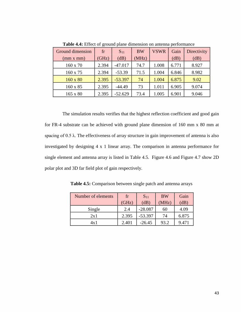
4.4 Effect of ground plane dimension on antenna performance 43
4.5 Comparison between single patch and antenna arrays 43
4.6 Performance analysis for different substrate materials 46
4.7 Comparison between antenna performance in free space and 47
on-body

xiii
4.8 Effect of varying skin and muscle thickness on single element 49
antenna performance
4.9 Effect of varying fat tissue thickness on single element antenna 49
performance
4.10 Effect of varying skin and muscle thickness on 2x1 array antenna 50
performance
4.11 Effect of varying fat tissue thickness on 2x1 array antenna 50
performance
4.12 Effect of varying skin and muscle thickness on 4x1 array antenna 51
performance
4.13 Effect of varying fat tissue thickness on 4x1 array antenna 51
performance
4.14 Impact of modification at transmission line on array antenna 52
performance for RT Duroid 5880
4.15 Simulated antenna gain on the body 52
4.16 Gain Improvement for the first design of 2x1 array antenna 53
4.17 Gain Enhancement for the second design of 2x1 array 56
4.18 Influence of length, L on the gain 57
4.19 Simulated overall antenna performance 60

1
CHAPTER 1: INTRODUCTION
1.1 Background
Development in wireless technologies creates new opportunities for Body-Centric
Wireless Communication (BCWC) which have gained huge attention among researchers and
industry players due to their promising applications in personal healthcare, military, sports
and body-sensor networks. Body centric wireless communication link between on-body
electronic devices and surrounding environment can be established with the help of antennas.
BCWC can be classified into three types based on the positions of the transmitter and receiver
[1]:
Off-body: Channel is off the body and in the free space and only one antenna in the
communication link is located on the body.
On-body: Most of the communication channel is on the surface of the body and both
transmitting and receiving antennas are mounted on the body.
In-body: Significant part of the channel is integrated into the body and implantable
antennas are used.
There are two primary challenges need to be considered by researchers for antenna
design for body-centric communication. The first challenge is to deal with degradation in
radiation efficiency, radiation pattern, gain and the shift in input impedance of the antenna
due to antenna-body interaction. Conventional antennas such as dipole [2], loop [3, 4], planar
inverted-F (PIFA) [5, 6] and microstrip patch [7-9] were used for body- centric
communications. The loop antenna is an omnidirectional antenna which gives maximum
radiation along the loop’s surface with E and H fields being perpendicular to each other [10].
A compact PIFA antenna has been designed for 2.4 GHz applications in [5] which also gives

2
an omnidirectional pattern. Patch antenna is a directional antenna that radiates power strongly
in specific directions. This characteristic of patch antenna enables it to be suitable for on-
body antenna design because maximum power need to be radiated away from the body.
Besides that, microstrip patch antennas have been a popular candidate for wireless
application due to their planar configuration and can be easily fabricated onto a printed circuit
board (PCB).
The second challenge is an antenna’s performance can be affected due to the strong
coupling between the antenna and the human body which may influence the user’s health.
Therefore, preventive or corrective measures should be implemented to ensure that its
performance does not change severely.
1.2 Problem statement
The purpose is to initiate communication with the body wireless is to provide the user
with comfort and flexibility instead of bulky and wired connection. Wireless Body Area
Network (WBAN) technology involves multiple sensor nodes located in-body or on-body
which facilitates in monitoring the surrounding environment. The data from the sensors will
be wirelessly transferred by antennas to an external computing facility. The antennas for
body-centric communication should be low profile, compact in size and insensitive to the
user’s body proximity.
Although microstrip patch antenna of single element has been a promising candidate
for body centric communication, it also suffers from several drawbacks such as narrow
bandwidth and low gain. Thus, to enhance the bandwidth and gain of the antenna, multi-
elements known as an array of single patch antenna can be designed. Furthermore, the study
of human body’s influence on antenna performance is crucial because human body anatomy

3
is unique for each individual. Behavior of electromagnetic waves propagating in the vicinity
of human body are determined by the thickness and composition of the body tissue. This is
because each body tissue has its own electrical property so variation in tissue thickness will
influence the ways the waves are reflected and absorbed. The single element and array
antennas proposed in this project is designed to operate for 2.4 GHz applications. An
investigation on the antenna's performance both in free space and on-body for various tissue
thickness are also investigated.
1.3 Aim and Objectives
The main aim of this project is to design on-body antennas that operate at 2.4 GHz
Industrial, Scientific and Medical (ISM) band. To accomplish this aim, the objectives of this
project include:-
1. To design and compare single element, 2x1 array and 4x1 array antenna’s
performance both in free space and on-body.
2. To investigate the influence of various tissue thickness on antenna’s performance.
3. To improve on-body antenna’s gain by adopting simple gain enhancement
techniques.

4
CHAPTER 2: LITERATURE REVIEW
2.1 Introduction
The basic concept of microstrip antenna is explored here. In the beginning of the
chapter also, wireless standards for body-centric communication antenna has been reviewed.
Antenna material characterization, feeding mechanism and also the concept of multi-
elements and its feeding technique also has been considered. Last but not least, the
importance of determining parameters of tissue layers is also discussed.
2.2 Frequency Allocation for WBAN
The Institute of Electrical and Electronics Engineers (IEEE) 802.15 Task Group 6
authorized a dedicated standard termed IEEE 802.15.6 for Body Area Network (BAN) in
2012. It constitutes the physical (PHY) and medium access control (MAC) layers specified
for short-distance wireless transmission in the vicinity of, or integrated into a human body
(but not limited to humans) for various applications such as healthcare monitoring for the
children or elderly, military or non-medical related. The requirements for BAN are the nodes
have to be simple, economical in terms, cost, consume low power and guarantee its users of
comfort. Thus, the standard features include three physical layers such as Narrowband (NB),
Ultra-Wide Band (UWB) and Human Body Communications (HBC). Figure 1 depicts a
spectrum allocation chart for all available frequencies for BAN applications.

5
Figure 2.1: Allocation of WBAN frequency bands in different countries [11]
The requirement for high data rate is crucial in medical application because a huge
amount of patients' data needs to be uploaded and transferred to the base station. The data
rate requirement for WBAN varies from 1 kbps to 1 Mbps. Furthermore, antenna design for
transmission and reception of data purposes has to be compact as to be possible. This can be
achieved by using higher frequency bands for antenna design as size is inversely proportional
to wavelength. Table 2.1 summarizes the characteristics of popular wireless standards for
medical application.
Table 2.1: Features of medical wireless technology
Wireless Description
Technology
• Frequency ranges from unlicensed 902 - 908 MHz, 2.4 - 2.45
GHz, 5.7 - 5.8 GHz
ISM Band • Easy to install and access, low power utilization, cost
effective
• Congested due to wireless coexistence
• Frequency ranges from 402 - 405 MHz
• Implantable antenna or devices are designed to work with
MedRadio or this band
MICS • Limitations in transmitting the signal as it has very low
power
• Maximum EIRP : 25 μW at 3m from MICS devices
• Bandwidth exceeds 500 MHz, which provides high
data rate
UWB • Low power consumption and complexity
• Can penetrate through obstacles easily

6
2.3 Microstrip Patch Antenna
Microstrip antennas are desirable over other type of antenna configurations due to the
distinctive characteristics such as low profile and flexibility in terms of resonant frequency,
propagation, far-field pattern, impedance matching when the specific radiator shape and
mode are selected. Additionally, they are also flexible to planar and nonplanar surfaces,
inexpensive to fabricate them by exploiting the cutting edge printed-circuit engineering, and
mechanically powerful when mounted on inflexible surfaces, suitable with MMIC designs
[10]. A conventional microstrip patch antenna is built by integrating a dielectric substrate
between radiating patch at the top and the ground plane as portrayed in Figure 2.2. The
radiating element and ground plane is usually fabricated by using conductive metals such as
copper or gold while the dielectric substrate is made of non-conducting material such as a
FR-4 board.
Figure 2.2: Microstrip patch antenna [10]
7
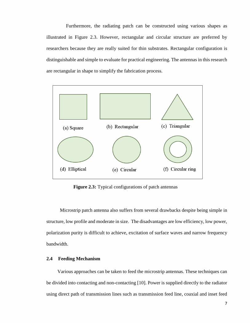
Furthermore, the radiating patch can be constructed using various shapes as
illustrated in Figure 2.3. However, rectangular and circular structure are preferred by
researchers because they are really suited for thin substrates. Rectangular configuration is
distinguishable and simple to evaluate for practical engineering. The antennas in this research
are rectangular in shape to simplify the fabrication process.
Figure 2.3: Typical configurations of patch antennas
Microstrip patch antenna also suffers from several drawbacks despite being simple in
structure, low profile and moderate in size. The disadvantages are low efficiency, low power,
polarization purity is difficult to achieve, excitation of surface waves and narrow frequency
bandwidth.
2.4 Feeding Mechanism
Various approaches can be taken to feed the microstrip antennas. These techniques can
be divided into contacting and non-contacting [10]. Power is supplied directly to the radiator
using direct path of transmission lines such as transmission feed line, coaxial and inset feed

8
in the contacting technique. Electronic coupling facilitates power transmission between the
feed line and the conducting element in the non-contacting technique. The four most popular
feeding techniques are feed line, coaxial, inset-feed and proximity coupling. However, only
feed line, inset –feed and coaxial feeding method will be reviewed in this research.
2.4.1 Transmission Line
A smaller in width radiating strip compared to the patch is linked to the edge of the
plot as exhibited in Figure 2.4. Such method allows the feed line and patch to be etched on
substrate resulting in a planar structure. The feed line can be directly connected to the patch
for the purpose of impedance matching. Its location and measurement can be adjusted to
result in desired impedance matching as well. Therefore, the transmission line feed simplifies
the modelling and fabrication process.
Figure 2.4: Transmission line feed [10]
2.4.2 Inset-Feed
Impedance of the feed line can be equated to the path without the aid of any extra
matching device with the creation of inset cut in the patch as displayed in Figure 2.5. The
matching can be done by adjusting the inset location. It is easy to fabricate such simple
feeding configuration and also provides good impedance matching of the antenna. In this

9
study, the authors found that the inset-feed contributed the best result in terms of gain and
reflection coefficient compared to strip line and quarter- wave feed [12].
Figure 2.5: Recessed inset-feed line [13]|
2.4.3 Coaxial Feed
The inner conductor of the coaxial connection is connected to the radiator, while the
outer part is linked to the ground as depicted in Figure 2.6. The benefits of this type of feeding
include it can be located at any preferred position, resulting in good impedance matching and
low spurious radiation. This feed is also easy to construct, making this technique to be
popular among researchers.
Figure 2.6: Coaxial-probe feed [10]|

10
The major drawback of probe-feed concept is that the connector sticks up from the
antenna plane, which is impractical for on-body applications. The antenna will be mounted
on the human body and thus, should not bring discomfort for the person who wearing the
antenna in terms of physical orientation. Additionally, the antenna should be of a flat and
planar configuration. Therefore, the inset-feed is chosen to feed the antennas.
2.5 Antenna Material Specification
Antenna’s performance is dependent on features of the materials used to develop them.
For this reason, it is really important for an antenna designer to have a good understanding
of the electrical properties of both conductive and non-conductive material that are readily
available in the market. After analyzing the electrical characteristics such as dielectric
constant and conductivity, suitable materials are selected to design antennas with good
radiation property and efficiency.
2.5.1 Substrate Materials
Antennas designed for on-body application should transmit energy perpendicular to
the flat structure and the ground plane and systematically protects the human body. Thus, the
radiation strength of the antenna is distinctively influenced by substrate’s dielectric constant
and thickness. Generally, low value of dielectric constant reduces surface wave losses that
are fixed to guided wave transmission within the substrate. Dielectric substrate’s thickness is
also vital for antenna design. The substrate that results in excellent antenna performance are
thick substrates with low electrical permittivity as it provides a large bandwidth. In addition
to it, a substrate with low loss tangent is also preferred to design high-gain antenna. The

11
electrical properties and features of the substrate materials used in this research is described
in the Table 2.2.
Table 2.2: Electrical properties of substrate materials
2.5.2 Conductive Materials
The choice of conductive metals for both patch and the ground plane also plays a
substantial role to guarantee efficient performance of the proposed antennas. Copper, gold,
silver and other metals are few conducting materials that available for commercial purposes
today. Conductive material with very low value of electrical surface resistivity is usually
chosen to reduce the antenna’s electrical losses.
2.6 Microstrip Antenna Arrays
Single element antenna gives broad radiation pattern in which the directivity and gain
values are relatively low. Although directivity and gain can be increased by enlarging the
size of the antenna, the main beam becomes narrower. As a consequence, side lobes also gets
larger. Since large antennas limit its performance, array configuration can be utilized.
Generally, the elements of an array are indistinguishable.
An array’s total field can be derived mathematically through vector addition of the
individual element’s field. It is expected that the amount of current flowing in each element
Properties RT Duroid 5880 R0 3730 FR - 4
Dielectric constant, εr, 2.20 ± 0.02 3.00 ± 0.06 4.3 - 4.7
10 GHz, 23 °C
Dissipation factor, tan δ 0.0009 0.0016 0.0025
10 GHz, 23 °C

12
is the same which is influenced by the distance between the elements and type of feeding
network. Five attributes can be tuned to obtain radiation pattern which are:
Geometrical structure (circular, rectangular and etcetera)
Spacing between antenna elements
Excitation phase of respective elements
Excitation amplitude of respective element
Pattern of individual elements
Multiple single elements can be arranged in a certain orientation to form an array of
antennas as highlighted in Figure 2.7. The goal of array design is to obtain the highest antenna
gain and directivity with minimal side lobe level. However, the arrangement of the elements
to form an array network is crucial for it to be successful.
Figure 2.7: Typical array antenna arrangement
As Figure 2.7 (a) indicates, a single line is adequate to feed the elements which is
also labeled as series-feed network. This technique is restricted to fixed- beam arrays or beam
–scanning arrays through frequency variation.
Linear array in Figure 2.7 (b) consists of N elements arranged along a line. The spacing
between the elements can be classified into two: equal or unequal. Number of elements to
put in a design primarily depends on the designer’s preference. Equally spaced linear array
d ≤ λ

13
is also termed as uniform array in which all the identical elements have same amplitude and
excitation phase.
In addition to the linear orientation of radiators, they also can be arranged in a grid to
form a planar array. Planar arrays are more functional as they provide a symmetrical radiation
pattern with smaller side lobes. Thus, it is more convenient to control the antenna beam with
this configuration. An antenna designer should emphasize on the distance between each
element while designing a series, linear or planar antenna which distance (d) ≤ lambda (λ) is
adapted. If d > λ, this will result in grating lobes in the antenna pattern. Grating lobe is
identical to the main beam but it is projected in an unintended direction. This research utilizes
linear arrangement of the antenna design.
2.6.1 Feeding Networks for Array Antenna
As discussed in the previous section, series elements can be fed by deploying a single
line. The second feeding technique involves multiple lines that is corporate-feed network.
Corporate-feed method splits power by 2n = 2, 4, 8 and etcetera. Implementation of this
technique provides the designer with freedom in controlling the amplitude and phase of each
element. The corporate-feed can be realized through the use of T-junction or Wilkinson
power divider.
2.6.1.1 Corporate Feed Configuration
If the transmission line loss is not taken into account, the T-junction can be
considered lossless. Thus, such junctions cannot be jointly matched to all ports. Power
division is done to ensure that equal power distribution among the N elements. Microstrip
lines of different impedance are considered for matching purposes. Hence, the arrangement

14
in Figure 2.8 (a) is applied for 2x1 linear array design that is for input 50 Ω line splits into
two output 100 Ω lines. The Wilkinson power divider technique allows matching of all ports
and isolation between output ports. This equal-split divider can be designed for 50 Ω input
impedance system by using a quarter - wave transformer to match the 50 Ω feed line to 100
Ω lines. Figure 2.8 (b) is a good illustration of the Wilkinson power divider concept. Feed
network of 4x1 array includes both T-junction and Wilkinson power divider.
Figure 2.8: Microstrip line feed network
2.7 Study of Biological Tissue Thickness based on Previous Research Works
The influence of electromagnetic wave propagation through the human tissue
dependent on thickness and dielectric characteristics of respective layers. The dielectric
properties, conductivity and thickness of body tissue vary from an individual to another with
age, gender and health conditions and also a particular region of the body. Furthermore, the
operating frequency of the electromagnetic wave also influences permittivity, conductivity
and penetration depth of the tissue layers. Penetrating microwaves will behave differently
due to alteration in penetration depth for these reasons [14]:
Electrical properties of body tissues depends on resonant frequency
Outer tissues penetration depth will be affected by propagation of microwaves
through different tissues

15
Scattering characteristic of the tissue changes as lambda (λ) varies
Body tissue can be classified into two types: high-water content and low-water
content [1]. Skin and muscles are some examples of the first type due to higher values of
permittivity and conductivity while fats of low permittivity and loss belong to the second
type. The skin organ covers the exterior of living organisms and acts as a barrier against
surrounding environment. Its tissue includes the epidermis, dermis and hypodermis as
evidenced in Figure 2.9. Hypodermis or subcutaneous adipose tissue (SAT) is located
underneath dermis layer. It provides mechanical protection, thermoregulation and energy
storage. Body region, age, gender and diet of an individual greatly affects the thickness of
the fat layer. Muscle tissue is generally considered as elastic and responsible to produce and
maintaining motion. Skeletal and cardiac muscles are able to contract and relax [3].
Therefore, it is necessary for a designer to identify complete compositions of tissue layers to
develop efficient antennas for body-centric communication. The most common regions of
human body preferred for on-body applications are arm, abdomen, chest or thigh. The
configuration and thickness of several tissue layers of different body parts reported in
literature are compiled in Table 2.3.
Figure 2.9: Composition of human skin [15]

16
Table 2.3: Human tissue thickness according to different body region
Reference Application Gender Tissue Model Body Thickness of body tissues
Configuration Parts (mm)
Skin (dry) Fat Muscle
[5] ISM Man Not
(2.4GHz) Rectangular Chest 4.5 2/4/10/8 stated
[16]
Not Rectangular Chest
2 10 28 5.6 GHz stated
Cylindrical Arm
[3]
0.96 15 13.5 ISM Adult Rectangular Frontal
(433 MHz) Thorax
[4]
MICS
4 4 52 (401-406 Not Cylindrical Not
MHz) stated stated
ISM
[6]
Chest 3 6 26
MICS Not Rectangular
(403.5
MHz) stated Abdomen 2 8 25
[17] Not Male
Rectangular Abdomen 2 9 7 stated (Taro)
[7] ISM Not
Rectangular Not
2 4 44 (2.45 GHz) stated stated
[8]
ISM Not
Rectangular
Not
1 2 10 (2.45 GHz) stated stated
[9] ISM Not
Rectangular Not
1 2 30 (2.45 GHz) stated stated
[2]
Rectangular
4 4 8 ISM Not Not
(2.45 GHz) stated stated
[18]
MICS Not
Rectangular
Not
5 13 35 (404 MHz) stated stated
[19]
MICS Not
Rectangular
3 4 20 (402-405 stated Chest
MHz)

17
Reference Application Gender Tissue Model Body Thickness of body tissues
Configuration Parts (mm)
Skin
(dry) Fat Muscle
[20]
MICS Not
Rectangular
4 4 20 (402-405 stated Trunk
MHz)
[21]
Not
Rectangular
Not
3 7 60 ISM stated stated
[22]
Children
Rectangular
0.6 - 1 0 - 16 30
BAN Frontal
Adult
Thorax 0.8 - 2.6
1.4 -
23.2 30
[23]
ISM Male
Rectangular
Not
1.6 - 3 0 - 15 20 and
25 (902-928) stated
[24]
Female Ellipsoidal
1.38 GHz
and Chest 2 15 5
2.88 GHz
[25]
MICS Not
Rectangular Arm 4 4 16 (403MHz) stated
ISM
(2.45 GHz)
[26]
Rectangular
1.5 - 2.5 0-23 0-30
0.9 - 17
GHz Not Not
stated stated
[27]
Rectangular
2 4 30 2.45 GHz Not Not
stated stated
[28]
Not
Rectangular
Forearm 2 2 20
Multiple stated Chest 3 3 20
Thigh 4 5 20

18
CHAPTER 3: METHODOLOGY
3.1 Introduction
Antenna design process of single and multi-elements are discussed in detail in this
chapter which includes material selection, calculation of the dimensions of both radiator and
feed and optimization. Next, their performance is evaluated both in free space and on-body
setting. This chapter also addresses several gain enhancement approaches to improve the
interaction between the antenna and body tissue.
3.2 Project Flow
This project is organized into 5 phases which are:-
a) Review related literature on properties of the material, antenna suitable for on-body
application, the concept of the antenna array and feeding mechanism
b) Further study on the actual thickness of tissue layers according to human body parts
c) Design single and array antenna at frequency of interest using transmission line
method
d) Compare and contrast the variation in antenna’s performance both in free space and
human body environment
e) Investigate on the significance of gain enhancement techniques in improving
antenna’s performance of on-body
These phases will be further explained by stages as follows: -

19
Stage 1:
Studies are conducted to understand the key concept and requirement of body-centric
wireless communication (BCWC). The selection of different laminate materials according to
the conductivity, permittivity and their respective thickness are emphasized. Moreover, a
study on antenna suited for on-body application also has been considered. Classification of
antenna arrays and their design requirement cited in literature also has been referred.
Stage 2:
Factors such as age, gender, dietary status and the anatomy of an individual will
influence the performance of the antenna. Therefore, knowledge of electromagnetic
properties of the body tissues and their respective thickness is crucial. At this stage, several
manuscripts in the literature are surveyed to obtain the actual thickness of the tissue layers
which are validated according to body parts.
Stage 3:
Attention is focused on designing the rectangular microstrip patch antenna using three
different substrate materials at 2.4 GHz. Dimensions of single element and array antenna are
calculated and optimized to meet requirement.
Stage 4:
The dimensions of antennas that provide best results in terms of reflection
coefficient, bandwidth, gain and etcetera are finalized. Thereafter, performance evaluation of
antenna’s on-body using three layer structure with uniform thickness respectively are carried
out as a preliminary. The antenna configurations that results in low loss will be used to
investigate the effect of the actual thickness of body tissue obtained from literature.

20
Literature review on material
properties, on-body and array
antennas, body tissue parameters and
feeding mechanism
Design and simulate single and array
antennas in free space
Investigate antenna’s performance due
to variation in tissue thickness
Implement gain enhancement
techniques
Data collection and analysis
YES
NO
NO
Stage 5:
The final step involves improving the performance of antennas that are mounted on-
body by selecting an actual configuration of three-layer structure. The numerical results of
gain enhancement will be elaborated in the next chapter.
Figure 3.1: Project flowchart
START
Meet
specification?
Meet
requirement?
END YES

21
3.3 Design Specification
3.3.1 Antenna Material Specification
The selected substrate materials should exhibit uniform dielectric constant, low loss
tangent and acceptable thickness. Two dielectric materials of Rogers Corporation such as RT
Duroid 5880 and R0 3730 are used in this research along with epoxy laminate, FR-4. The
radiator and the ground plane are designed using conductive material such as pure copper.
The specification of all materials used are listed in Table 3.1. Full material description of
Roger’s laminates can be found at Appendix A and Appendix B.
Table 3.1: Electrical properties of the dielectric and conductive materials
Material RT/ duroid R0 3730 FR-4 Pure Copper Aluminium
Parameter 5880
Dielectric constant, 2.2 3 4.7 - -
εr
Conductivity, - - - 5.96e+007 3.56e+007
S/m
Dissipation factor, 0.0009 0.0016 0.0025 - -
tan δ
Thickness, h (mm) 1.6 1.534 1.6 0.035 1
3.3.2 Design Methodology
The initial parameters and dimension of a single rectangular patch antenna can be
computed based on Transmission Line Model equation. The width of the patch for specific
resonant frequency, fr is determined using equation 3.1:
𝑊 = 𝐶
2 𝑓r √
2
𝜀𝑟+1 (3.1)

22
Since the edges of the patch will experience fringing effect, some of the lines of
electric field will pass through the air instead of the substrate medium. Therefore,
modification need to be done to the relative permittivity whereas physical length of the patch
is also extended from its original configuration. The effective dielectric constant, εeff and the
extended incremental patch length, ∆𝐿 are given by
𝜀𝑒𝑓𝑓 =𝜀𝑟+1
2+
𝜀𝑟−1
2(1 + 12
ℎ
𝑤)−
1
2 (3.2)
∆𝐿 = 0.412ℎ (𝜀𝑒𝑓𝑓+0.3)(
𝑤
ℎ+0.264)
(𝜀𝑒𝑓𝑓−0.258)(𝑤
ℎ+0.8)
(3.3)
Thus, the accurate patch length is calculated through equation 3.4 as shown:
𝐿 =𝐶
2𝑓√𝜀𝑒𝑓𝑓− 2∆𝐿 (3.4)
The patch requires characteristic impedance of 50 Ω for its feed line. Therefore, inset-
feed method can be used to equate the input resistance to the feed. First, conductance, G1 and
mutual conductance, G12 must be computed to obtain input resistance as stated in equation
3.5 and equation 3.6:
𝐺1= 1
120𝜋2 ∫ [sin(
𝑘0𝑊
2cos 𝜃)
cos 𝜃]
2𝜋
0𝑠𝑖𝑛3 θ 𝑑𝜃 (3.5)
𝐺12= 1
120𝜋2 ∫ [sin(
𝑘02
cos 𝜃)
cos 𝜃]
2𝜋
0𝐽0 (𝑘0 𝐿 sin 𝜃)𝑠𝑖𝑛3 θ 𝑑𝜃 (3.6)
Where, Jo is the Bessel function of the first kind of order zero while ko is wavenumber.
Next, the input resistance is then obtained by

23
𝑅𝑖𝑛 = 1
2 (𝐺1+𝐺12) (3.7)
Finally, the input resistance at y = yo from the edge can be computed using equation 3.8:
𝑅𝑖𝑛 (𝑦0)=𝑅𝑖𝑛
(0) 𝑐𝑜𝑠2 (𝜋
𝐿𝑦0) (3.8)
At yo, matching is made as the input resistance is 50 Ω. The inset feed length, yo can be
solved using Matlab solver.
3.4 Antenna Design in Free Space
3.4.1 Single Element Design
In the previous section, procedures to determine patch length and width and inset feed
length for single element are described. The calculated dimensions are tabulated in Table 3.2.
Table 3.2: Dimensions of single patch antenna
Parameters Values (mm)
RT Duroid 5880 R0 3730 FR - 4
Patch length,Lp 49.4 44.2 29.6
Patch width,Wp 41.3 35.6 37.02
Feed length,Lf 23 20.1 17.29
Feed Width,Wf 4.93 3.86 3.137
Inset feed,yo (50 ohm) 14.503 12.74 9.96
Inset feed,yo (100 ohm) 11.55 10.36 8.995

24
49 mm
80 mm
80 m
m
40.6
mm
22 m
m
4.75 mm
14
(a) RT Duroid 5880
80 mm
80 m
m
22.2
mm
34.9
mm
44 mm
3.67 mm
12
.7 m
m
1 mm
1 mm
(b) R0 3730
CST Microwave Studio software is used to design and optimize all antenna
configurations. The final dimensions of proposed single patch antenna for RT Duroid 5880
and R0 3730 substrates are illustrated in Figure 3.2. Final geometry of single- element
antenna using FR-4 can be acquired from research findings of previous candidate. It is worth
mentioning that both substrate and ground share the same dimension that is 80 mm x 80 mm.
Figure 3.2: Front view of single patch antenna

25
3.4.2 Array Antenna Design
3.4.2.1 Array Antenna for FR – 4
Selection of number of elements and separation between them is imperative in
maximizing the performance of a linear antenna array. Figure 3.3 displays structure of 2x1
and 4x1 linear array with 0.5λ spacing respectively. Patch elements are also configured in
grid manner as portrayed in Figure 3.4. The both arrays are designed with length and width
of each element is intriguingly identical to the single patch design. To design four element
array, 50 Ω need to be matched to 100 Ω transmission line by determining the characteristic
impedance. It can be calculated by
Zc = √Z0Rin (3.9)
= √(50Ω)(100Ω)
= 70.71 Ω
The impedance calculation for 50 Ω, 70.71 Ω and 100 Ω feed line is outlined in Table 3.3.
Table 3.3: Feedline impedance computation
Material Impedance (Ω) Dimension (mm)
Length Width
FR - 4
50 17.29 3.137
70.71 17.1 1.52
100 17.5 0.7
RT Duroid 5880
50 23 4.75
70.71 23.2 2.83
100 23.6 1.43
RO 3730
50 20.1 3.67
70.71 20.5 2.15
100 20.9 1.03

26
d = 0.5λ
2.9 mm
160 mm
61.25 mm
mm
80 m
m
28.7
mm
1 mm
8.6
mm
(a) 2x1 Array
d = 0.5λ
252.6 mm
100 m
m
1 mm
1.5 mm 2.9 mm
39.5 mm
28.6
mm
(b) 4x1 Array
9 m
m
Figure 3.3: Geometry of array antenna for FR-4 substrate

27
160 mm
90 m
m
49 mm
40.2
mm
4.75 mm 1.4 mm
11
.5 m
m
Figure 3.4: 2x2 array antenna for FR-4 substrate
3.4.2.2 Array Antenna for RT Duroid 5880
Array of 2 and 4 elements arranged in linear manner are designed using RT Duroid
5880 with the same design procedure for comparison purposes. Figure 3.5 highlights the
dimensions of array antenna.
(a) 2x1 Array

28
270 mm
100 m
m
4.75 mm
1.4 mm
2.6 mm
49 mm
40.4
5 m
m
11
.5 m
m
150 mm
44 mm
34.5
5 m
m
3.68 mm 1 mm
80 m
m
10
.36
mm
mm
(b) 4x1 Array
Figure 3.5: Design specification for RT Duroid 5880 antenna array
3.4.2.3 Array Antenna for R0 3730
Figure 3.6 represents architecture of 2x1 and 4x1 linear array for R0 3730 also with
0.5λ spacing.
(a) 2x1 Array

29
250 mm
80 m
m
(b) 4x1 Array
Figure 3.6: Geometry of array antenna for R0 3730 substrate
3.5 Antenna Design for On-Body Communication
The proposed antennas are placed on three-tissue layer that represents human body
model as visualized in Figure 3.7. The electrical properties of the tissue layers can be obtained
from database [29, 30] and are stated in Table 3.4. A uniform thickness 3mm is considered
for the skin, fat and muscle tissue respectively to investigate the interaction of
electromagnetic waves with biological tissues. The dimensions of tissue layers are set equal
according to antenna configurations.
Table 3.4: Electrical properties of body tissues at 2.4 GHz
Tissue Relative Conductivity (S/m), Penetration depth
Type permittivity σ (mm)
Skin (Dry) 38.1 1.441 23
Muscle 52.7 1.705 23
Fat 5.285 0.102 119.6
3.68 mm
1 mm
2 mm
9 m
m
34
.55
mm
44 mm

30
3 mm skin
3 mm fat
3 mm muscle
(a) Single element
(b) 2x1 array
(c) 4x1 array
Figure 3.7: Antennas on human body tissue for RT Duroid 5880 substrate

31
3.5.1 Parametric study of variation in body tissue thickness
Based on the preliminary antenna simulations for on-body setting, it is discovered that
RT Duroid 5880 provides low gain loss comparatively. Therefore, antennas designed using
that substrate will be used to evaluate its performance on-body with actual thickness of body
tissues. Based on literature, the thickness of human skin ranges from 1mm to 5 mm depending
on body regions. Variation in muscle and fat tissue thickness is related to factors such as age,
gender, nutritional status and body parts of an individual. In addition, subcutaneous adipose
tissue thickness also changes with Body Mass Index (BMI). It is ratio of amount of body
lipid correlated to height and weight of individual. Table 3.5 reports the thickness of fat tissue
according to BMI classification.
Table 3.5: Hypodermis Layer in the Chest near Shoulder Area of People with Different
BMI [31]
BMI Man Hypodermis Woman Hypodermis
(mm) (mm)
Underweight <3 <7
Normal 3-5 7-10
Overweight 6-16 11-20
Obese >16 >20
Muscle thickness is considered to be variable parameter that ranges from 7 mm [17] to
60 mm [21]. This research focuses on designing antennas to be placed on chest of an adult.
Parametric analysis is carried out by setting the skin thickness for 2 mm, 3mm and 4.5 mm
while the muscle layer is labeled as 20 mm thick. The thickness of fat tissue is assigned
according to BMI classes respectively: 2mm/4mm/10mm/18mm for man and
3mm/9mm/15mm/21mm for woman.

32
3 mm skin
3 mm fat
20 mm muscle
3.5.2 Gain Enhancement Techniques for On-Body Antennas
Transmission line are critical part of antenna design as it is used for the purpose of
impedance matching and minimize power loss from the antenna. Antenna reactive fields
interact with the body resulting in degradation of input impedance, gain and efficiency.
Therefore, modification is done to the transmission line in Figure 3.8 by blending the edge
as indicated in Figure 3.10 to improve impedance matching and gain. Note that the tissue
thickness is assigned as 9 mm for the original structure. Different approach has been proposed
in this research to overcome the disadvantage of antenna-body interaction by using the simple
body model configuration in Figure 3.9. The thickness of body tissue is validated in [28].
Figure 3.8: Original structure of 2x1 array antenna on-body
Figure 3.9: 2x1 array antenna on human chest model

33
Figure 3.10: Modifications implemented on the design
Then, modification of feed structure are proposed by increasing its length from
15 mm to 22 mm. In addition, current path of antenna is also altered due to adjustment of
transmission line. The final dimension of feed length is 27 mm. Gain enhancement approach
includes addition of superstrate for terahertz application [32] and usage of metamaterials
such as EBG structure [33]. Superstrate is a dielectric layer of specific thickness placed on
top of radiator which results in additional complexity. A recently reported work [34]
proposed placement of hemispherical lens and parasitic ring on top of skin layer to improve
the gain of an implantable antenna. The effectiveness of parasitic elements in increment of
antenna gain for free space communication also has been discussed in [35]. Parasitic
elements should be placed at optimum distance from driven element as it need to receive
radiation from main radiator.
Two parasitic strips with dimension 12 mm x 36 mm are vertically placed 9 mm
away from the main radiator. Since the type of material used to design parasitic elements
and their shape may influence antenna performance, a circular parasitic ring with a radius of

34
10 mm and 2 mm wide is placed adjacent to the main feed in the earlier stage. The influence
of different shape configuration is then investigated by replacing the circular ring with
hexagon ring made of pure copper. Further experiment is also conducted by changing the
materials of the hexagon ring from pure copper to another conductive material, aluminium.
This antenna array is further modified by cutting four diamond slots, two at the parasitic
strips and another two is at the dual patches and two octagon slots at the strips as well. Last
but not least, two square slots of 20 mm x 20 mm dimension are also removed from the
substrate. The final structure of proposed array antenna is displayed in Figure 3.11.
The authors in [35] investigated the effect of parasitic patches in multi-banding and
gain enhancement of microstrip antenna. Double dip is observed in the reflection coefficient
graph because the four parasitic patches elements are connected to the main patch resulting
in strong near-field coupling. In this research, the impact of multi-parasitic elements in gain
increment also has been investigated. Firstly, a single parasitic strip is placed adjacent to the
radiator. Then, another parasitic strip is added consecutively resulting in four parasitic
170 mm
90
mm
49 mm
42.0
77 m
m
4.719 mm
9 mm
11
mm
12 mm
36
mm
27
mm
6.33 mm 3.06 mm
5.6
6 m
m
1.4 mm
10 mm 8 mm
Figure 3.11: Final proposed geometry of 2x1 array on-body antenna

35
elements along the main radiator as depicted in Figure 3.12. Note that all parasitic elements
shares the same shape and width but vary in length.
4x1 array on-body antenna is also modified by curving the edge of transmission lines.
Furthermore, change is also implemented at the feedline by lengthening its length to 28 mm.
This results in alteration of current path as well. Two square slots of 14 mm x 14 mm
dimension are also cut from the substrate. The final dimensions of proposed 4x1 array
antenna and substrate configuration are shown in Figure 3.14 and Figure 3.15 respectively.
49 mm
42
.02
mm
40
mm
10 mm 3 mm
3 mm
Figure 3.12: Proposed second design of 2x1 array on-body antenna
30 mm
20
mm
Figure 3.13: Final dimension of slots in substrate for both design

36
49 mm 8 mm
4.005 mm
4.74 mm
28 mm
41
.12
mm
40
mm
Figure 3.14: Final proposed 4x1 on-body antenna array
Figure 3.15: Substrate geometry of 4x1 on-body antenna array
14 mm 1
4 m
m

37
CHAPTER 4: RESULTS AND DISCUSSIONS
4.1 Introduction
The evaluation of antenna performance in two scenarios, first one in free space and
then onto the human body is presented in this chapter. The characteristics of antennas include
reflection coefficient, bandwidth, efficiency, VSWR, radiation pattern, gain and directivity.
Parametric analysis of on-body antennas due to variation in tissue thickness are also
described here. The last section of this chapter presents several improvement techniques of
antenna performance to minimize the antenna-body coupling.
4.2 Antenna Performance in Free Space
4.2.1 Dimensional Analysis of Single Element Patch Antenna
It is crucial to investigate the influence of parameters such as length and width on
antenna performance. This can be realized by varying the antenna parameters of patch, feed
transmission line and etcetera during the designing stage. The optimization process aids an
antenna designer in selecting the best antenna configuration. This section highlights the
numerical analysis of parametric study performed on single element patch antenna for RT
Duroid 5880 substrate. Reflection coefficient, S11 is calculated by varying the inset feed
length, notch gap width and patch length and width.
Reflection coefficient, S11 represents the ratio of amplitude of reflected voltage wave,
V- to incident voltage wave, V+ at the load. It describes how much power is returned to the
transmitter device. Reflection of power occurs when an antenna is mismatched to the
receiver. In order to ensure that an antenna received maximum power, the source impedance

38
Figure 4.1: Influence of inset feed length, yo on antenna performance
Figure 4.2: Influence of notch gap width, g on antenna performance
and transmission line must be well coordinated to its characteristic impedance. To design a
good antenna, S11 of less than -10 dB must be achieved which implies 90 % of the input
power is transmitted and the remaining 10 % of the power is reflected.
Figure 4.1 reveals that there has been only slight variation in reflection coefficient, S11
when the length of the inset feed, yo is increased from 14 mm to 14.5 mm with a step size
of 0.1 mm. The S11 value at 2.4 GHz is -32.247 dB which when yo is 14 mm and -20.988
dB for 2.3988 GHz when yo is tuned to 14.5 mm. It has been mentioned in the previous

39
chapter that yo is the inset length from the radiating edge. Based on the theory mentioned in
[10], varying the location of where the feed line connects to the patch antenna, input
impedance can be controlled. Therefore, selection of inset length of 14 mm indicates that the
patch impedance is closer to the feed line impedance. Figure 4.3 shows that at 2.4 GHz, the
input impedance is almost at the point ‘1’ of the unit circle of the smith chart. This denotes
the real part of the impedance is almost 50 Ω which represents good impedance matching.
Figure 4.3: Smith chart
Figure 4.2 illustrates the dependency of resonant frequency with notch gap width, g.
The operating frequency is deviated slightly with variation in the inset feed width. When g
is incremented from 1 mm to 1.4 mm, the frequency shifts from 2.4 GHz to 2.3971 GHz with
S11 of -17.268 dB. In contrast, the frequency shifts to the right to 2.401 GHz when g is 0.8
mm with S11 of -28.991 dB. The best impedance matching can be achieved when the width,
g is set at 1 mm where the S11 value is -33.044 dB at 2.4 GHz.

40
Figure 4.4: Impact of patch length, Lp on antenna performance
Figure 4.5: Impact of patch width, Wp on antenna performance
The S11 graphs in Figure 4.4 and Figure 4.5 represent the impact of varying patch
length, Lp and patch width, Wp respectively. A sharp dip is observed when Lp is tuned to 48
mm. It marks a value of -67.402 dB at 2.402 GHz. Besides that, a bandwidth of 43.7 MHz
is also achieved for 2.4 GHz ISM band. On the contrary, S11 value at 2.4 GHz is -33.044 dB
when Lp is increased to 49 mm. A bandwidth of 47.4 MHz is achieved for that particular
center frequency which is comparatively higher.

41
Table 4.1: Final dimensions of single element patch antenna
A distinct shift in frequency is observed in Figure 4.5 when the patch width is
decreased by -0.2 mm. An accurate explanation for this is that the patch width is inversely
proportional to the operating frequency proven by equation 3.1. A S11 value of -21.713 dB
is obtained at 2.3932 GHz when the width of the patch, Wp is equivalent to 40.7 mm. Further
shift is detected when Wp is decreased to 40.5 mm. The S11 shifts from its initial position to
the left that is 2.4044 GHz. This signifies that performance of an antenna is extremely
responsive to the patch width parameter. Thus, it need to be tuned to an optimum value to
achieve targeted results.
The final values of dimension which gives best reflection coefficient, S11 at required
operating frequency are selected and stated in Table 4.1:
Parameter Lp Wp yo g
Dimension (mm) 49 40.6 14 1
4.2.2 Performance Analysis of Single Element and Antenna Arrays
The goal of antenna array design is to achieve high gain and directivity which are
dependent on number of elements selected based on requirement. The elements can be
arranged in many ways on a substrate to form various geometry. Antenna configuration can
be classified as linear, planar, and circular and etcetera. The overall radiation pattern of
antenna array is shaped by taking number of elements used and spacing between them into
consideration. The simulation process is initiated with two elements aligned in linear form
with inter-element spacing of 0.4λ, 0.45λ and 0.5λ for FR-4 substrate. The 2x1 antenna array

42
Table 4.2: Influence of IES between elements on antenna performance
Table 4.3: Effect of IES between elements on HPBW
has a ground dimension of 160 mm x75 mm. The simulation results for 2x1 array antenna
are recorded in Table 4.2.
IES spacing fr S11 BW VSWR Gain Directivity
(d) (GHz) (dB) (MHz) (dB) (dB)
0.5 λ 2.394 -53.39 71.5 1.004 6.846 8.982
0.45 λ 2.396 -37.629 74.3 1.003 6.704 8.751
0.4 λ 2.4014 -21.948 66 1.173 6.483 8.481
Radiation pattern in E-plane is more significant for electrical type antennas. The
E-plane cut is obtained by varying the theta, θ while keeping phi, φ constant. Thus, the
stimulated gains are recorded when phi is equivalent to zero. The highest gain and directivity
is recorded when the two elements are spaced apart by 0.5λ. Half Power Beam Width
(HPBW) is the coverage angle of an antenna within acceptable half-power limit (-3dB).
Additionally, side lobes are beam that are adjacent to main lobe. A diminutive decrease in
SLL and a gradual increase in HPBW is noticed when the elements spacing is reduced from
0.5λ to 0.4λ. The spacing between the elements is fixed at 0.5 λ.
Further experiment is conducted by varying the ground plane dimension. Table 4.4
describes the influence of varying ground plane dimension on antenna performance:
0.4 λ 0.45 λ 0.5 λ
Element HPBW SLL (dB) HPBW SLL (dB) HPBW SLL (dB)
2 58.1° -14.8 54.2° -14.9 50.8° -15
43
Table 4.4: Effect of ground plane dimension on antenna performance
Table 4.5: Comparison between single patch and antenna arrays
Ground dimension fr S11 BW VSWR Gain Directivity
(mm x mm) (GHz) (dB) (MHz) (dB) (dB)
160 x 70 2.394 -47.017 74.7 1.008 6.771 8.927
160 x 75 2.394 -53.39 71.5 1.004 6.846 8.982
160 x 80 2.395 -53.397 74 1.004 6.875 9.02
160 x 85 2.395 -44.49 73 1.011 6.905 9.074
165 x 80 2.395 -52.629 73.4 1.005 6.901 9.046
The simulation results verifies that the highest reflection coefficient and good gain
for FR-4 substrate can be achieved with ground plane dimension of 160 mm x 80 mm at
spacing of 0.5 λ. The effectiveness of array structure in gain improvement of antenna is also
investigated by designing 4 x 1 linear array. The comparison in antenna performance for
single element and antenna array is listed in Table 4.5. Figure 4.6 and Figure 4.7 show 2D
polar plot and 3D far field plot of gain respectively.
Number of elements fr S11 BW Gain
(GHz) (dB) (MHz) (dB)
Single 2.4 -28.087 60 4.09
2x1 2.395 -53.397 74 6.875
4x1 2.401 -26.45 93.2 9.471

44
Figure 4.6: Gain 2D polar plot at xz plane for antenna arrays

45
Figure 4.7: Gain 3D far field plot for antenna arrays
The reflection coefficient, S11 is the best for 2x1 array configuration which denotes
excellent impedance matching. Moreover, it is clearly noticed that bandwidth and gain
increases as number of elements increases. The illustrations in Figure 4.6 show narrower
main beam width of array antenna is obtained by increasing the number of elements. This
further confirms the theory that higher gain or directivity can be achieved with smaller beam

46
Table 4.6: Performance analysis for different substrate materials
area. The comparison of radiation pattern between 2x1 array and 4x1 array antenna as shown
in Figure 4.7 clearly reveals that the radiation gets more intensified at the center of a sphere.
In this research, the proposed four elements array antennas are of linear configuration. The
rationale behind this selection is that 2x2 array is not a highly directional antenna as it exhibits
two major lobes. The signal is directed to 27 degree with HPBW of 31.9 degree as depicted
in Figure 4.5 (c). The disadvantage of such arrangement is that the power is not focused at
one particular direction only but it is radiated in other direction as well. A high gain of 9.471
dB is achieved with 4x1 compared to 7.482 dB by 2x2 array configuration.
At initial stage, the design and simulation process of antennas were carried out by
using FR-4 substrate. In order to select the best configuration for antennas, the comparison
were made by replacing the original substrate with RT Duroid 5880 and R0 3730. The
simulation results for both materials are described in Table 4.6.
Materials Number of fr S11 BW Gain Directivity η
elements (GHz) (dB) (MHz) (dB) (dB) (%)
RT Duroid Single 2.4 -33.028 48.6 6.667 7.239 92
5880 2x1 2.401 -23.178 38.9 9.399 9.915 94.7
4x1 2.4 -15.297 37.6 12.12 12.57 96.4
Single 2.4 -31.697 37.6 6.283 7.119 88.3
R0 3730 2x1 2.4 -18.13 46.2 8.425 9.114 92.4
4x1 2.4 -17.845 36.1 11.01 11.8 93.3
4.3 Antenna Performance on the Human Body
The proposed antennas behavior are analyzed in the propinquity of simplified three-
layer human body model. The thickness of each body tissue is set at 3 mm. The comparison
between characteristics of the antenna in air and on the body is presented in Table 4.7.

47
Table 4.7: Comparison between antenna performance in free space and on-body
Number of Antennas Performances
Material elements Free-space (In air) On the Human Body Gain Difference Gain Difference
Fr
(GHz)
S11(dB) BW(MHz)
Gain
(dB)
Fr
(GHz) S11(dB) BW(MHz)
Gain
(dB) (dB) (%)
Rogers RT/ Single 2.4 -33.028 43.2 6.667 2.4 -17.161 36.8 7.009 0.342 105.1
Duroid 2 x 1 2.401 -23.178 48.6 9.399 2.4 -25.284 53.8 9.23 -0.169 1.8
5880 4 x 1 2.4 -15.297 38.9 12.12 2.4 -35.173 52.3 11.95 -0.17 1.4
Rogers Single 2.4 -31.697 37.6 6.283 2.4 -22.341 35.9 6.28 -0.003 0.005
RO 3730 2 x 1 2.4 -18.13 46.2 8.425 2.4 -20.895 47 8.12 -0.305 3.62
4 x 1 2.4 -17.845 36.1 11.01 2.4 -13.394 33.1 10.84 -0.17 1.54
FR4 Single 2.4 -28.087 60 4.09 2.412 -22.092 50.4 3.37 -0.72 17.6
2 x 1 2.395 -53.397 74 6.875 2.401 -43.187 70.7 6.452 -0.423 6.15
4 x 1 2.401 -26.45 93.2 9.471 2.4 -22.87 101.3 8.563 -0.627 6.82

48
It is noticed that the reflection coefficient, S11 is shifted from 2.395 GHz to 2.401
GHz when 2x1 array antenna for FR-4. In addition, the S11 is greatly reduced from -53.397
dB to -43.397 dB as the input impedance of antenna detuned from 50.07 Ω to 50.01 Ω. This
clearly shows that antenna’s reactive field is very sensitive to the vicinity of the body. The
existing models of RT Duroid 5880 and R0 3730 on-body antennas are redesigned to meet
the requirement of 2.4 GHz ISM band.
It is also can be seen distinctly that radiation pattern and gain of the antennas are
affected by the interaction. Antenna gain is naturally reduced due to absorption of power by
the body tissues. However, gain increases by 0.342 dB for single element antenna for RT
Duroid 5880 as a result of reflections from the body. The comparative study also reveals that
RT Duroid 5880 results in low gain loss compared to FR-4 of the same thickness, 1.6 mm.
Such performance is attributed by low loss tangent value of 0.0009 compared to 0.0025 for
FR-4. Therefore, it can be concluded that RT Duroid 5880 is the best substrate material to
design on-body antenna.
4.3.1 Parametric Analysis of Variation in Body Tissue Thickness
The performance of the antenna configurations designed using RT Duroid 5880 are
evaluated by placing them on the realistic body tissue. The parametric investigation is carried
out by varying the thickness of a body tissue while keeping others constant at chest region.
Table 4.8 and Table 4.9 verifies the effect of varying tissue thickness on single element
antenna performance.

49
Table 4.8: Effect of varying skin and muscle thickness on single element
antenna performance
Table 4.9: Effect of varying fat tissue thickness on single element antenna
performance
From the extensive simulation results, it can be observed that the antenna gains
are increased when placed onto the human chest. All the various thickness scenarios exhibits
gain increment compared to free space setting which is 6.667 dB for single element antenna.
There is no correlation between reflection coefficient, S11 and tissue thickness as only a slight
variation trend for S11 and bandwidth is noticed. Besides that, the highest antenna gain is
observed for fat tissue thickness of obese man and woman respectively. A rising trend is also
revealed when the hypodermis layer thickness is set from 9 mm onwards. Such results show
Body
Tissue Gender
Layer
Thickness
Fr
(GHz) S11(dB) BW(MHz)
Gain
(dB)
Type (mm)
Skin Adult 2 2.4 -17.159 36.5 7.033
3 2.4 -17.161 36.8 7.009
4.5 2.4 -16.948 36.2 6.943
Muscle Adult 20 2.4 -16.64 35.7 6.832
Body
tissue Gender BMI
Layer
thickness Fr S11 BW Gain
type Classification (mm) (GHz) (dB) (MHz) (dB)
Fat
Man Underweight 2 2.4 -17.242 36.7 7.064
Normal 4 2.4 -17.045 36.6 6.931
Overweight 10 2.4 -16.428 35.2 6.909
Obese 18 2.4 -16.76 36 7.353
Woman Underweight 3 2.4 -17.161 36.8 7.009
Normal 9 2.4 -16.41 35.5 6.814
Overweight 15 2.4 -16.699 35.8 7.259
Obese 21 2.4 -16.816 36.2 7.383

50
Table 4.10: Effect of varying skin and muscle thickness on 2x1 array antenna
performance
Table 4.11: Effect of varying fat tissue thickness on 2x1 array antenna
performance
that reflection effect from the body is very strong as fat layer being less conductive separates
the proximity between two highly conductive skin and muscle tissue.
As previously stated, the 2x1 array configuration is remodeled to match the input
impedance back to 50 Ω. Only a slight change occurs to the reflection coefficient, S11 value
as a consequence of variation in tissue thickness. Additionally, no change occurs to the
bandwidth. Therefore, near field of 2x1 array antenna is less sensitive to the varying nature
of body tissue. However, its radiation property is slightly affected because of deviation in
gain value.
Body Tissue Gender Layer Thickness Fr (GHz) S11(dB) BW(MHz) Gain (dB)
Type (mm)
Skin Adult 2 2.4 -25.388 53.8 9.266
3 2.4 -25.284 53.8 9.23
4.5 2.4 -25.098 53.8 9.293
Muscle Adult 20 2.4 -25.202 53.7 9.346
Body tissue Gender BMI Layer thickness Fr S11 BW Gain
type Classification (mm) (GHz) (dB) (MHz) (dB)
Fat
Man Underweight 2 2.4 -25.353 53.8 9.283
Normal 4 2.4 -25.218 53.8 9.207
Overweight 10 2.4 -25.558 53.8 9.518
Obese 18 2.4 -26.007 53.8 9.566
Woman Underweight 3 2.4 -25.284 53.8 9.23
Normal 9 2.4 -25.455 53.8 9.5
Overweight 15 2.4 -25.962 53.8 9.549
Obese 21 2.4 -25.947 53.8 9.57

51
Table 4.12: Effect of varying skin and muscle thickness on 4x1 array antenna
performance
Table 4.13: Effect of varying fat tissue thickness on 4x1 array antenna
performance
Body
Tissue Gender
Layer
Thickness
Fr
(GHz) S11(dB) BW(MHz)
Gain
(dB)
Type (mm)
Skin Adult 2 2.4 -35.435 52.3 11.95
3 2.4 -35.173 52.3 11.95
4.5 2.4 -34.912 52.3 11.93
Muscle Adult 20 2.4 -35.081 52.3 11.91
Similar trend is observed for reflection coefficient, S11 and bandwidth of 4x1
array antenna. The antenna still provides S11 <- 10 dB with bandwidth of 52.3 MHz compared
to 38.9 MHz at free space. The gain value slightly decreased by the range from 1.4 % to 1.6
% when the skin thickness increases. The slightest variation in gain is recorded for
hypodermis thickness of obese woman which is 0.5 %.
Body
tissue Gender BMI
Layer
thickness Fr S11 BW Gain
type Classification (mm) (GHz) (dB) (MHz) (dB)
Fat
Man Underweight 2 2.4 -35.135 52.3 11.96
Normal 4 2.4 -35.175 52.3 11.94
Overweight 10 2.4 -34.568 52.3 11.89
Obese 18 2.4 -34.239 52.3 12.02
Woman Underweight 3 2.4 -35.173 52.3 11.95
Normal 9 2.4 -34.679 52.3 11.89
Overweight 15 2.4 -34.253 52.3 11.97
Obese 21 2.4 -34.34 52.3 12.06
52
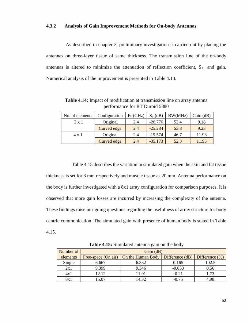
Table 4.14: Impact of modification at transmission line on array antenna
performance for RT Duroid 5880
Table 4.15: Simulated antenna gain on the body
4.3.2 Analysis of Gain Improvement Methods for On-body Antennas
As described in chapter 3, preliminary investigation is carried out by placing the
antennas on three-layer tissue of same thickness. The transmission line of the on-body
antennas is altered to minimize the attenuation of reflection coefficient, S11 and gain.
Numerical analysis of the improvement is presented in Table 4.14.
Table 4.15 describes the variation in simulated gain when the skin and fat tissue
thickness is set for 3 mm respectively and muscle tissue as 20 mm. Antenna performance on
the body is further investigated with a 8x1 array configuration for comparison purposes. It is
observed that more gain losses are incurred by increasing the complexity of the antenna.
These findings raise intriguing questions regarding the usefulness of array structure for body
centric communication. The simulated gain with presence of human body is stated in Table
4.15.
No. of elements Configuration Fr (GHz) S11(dB) BW(MHz) Gain (dB)
2 x 1 Original 2.4 -26.776 52.4 9.18
Curved edge 2.4 -25.284 53.8 9.23
4 x 1 Original 2.4 -19.574 46.7 11.93
Curved edge 2.4 -35.173 52.3 11.95
Number of Gain (dB)
elements Free-space (On air) On the Human Body Difference (dB) Difference (%)
Single 6.667 6.832 0.165 102.5
2x1 9.399 9.346 -0.053 0.56
4x1 12.12 11.91 -0.21 1.73
8x1 15.07 14.32 -0.75 4.98

53
Table 4.16: Gain improvement for the first design of 2x1 array antenna
4.3.2.1 Improvement Results for First Proposed Design of 2x1 Array Antenna
Table 4.16 summarizes the simulated gain obtained through implementation of
modification technique for the first proposed antenna structure.
Alteration done to transmission line structure compared to standard transmission
line and the feed length improves the current path resulting in gain enhancement by 0.113
dB. Additional improvement is made with the placement of a circular parasitic ring adjacent
to the T-junction which yields a gain increment of 0.015 dB. The logic behind this is that the
fringing fields at antenna edges facilitates the emission of microstrip patch antenna. Thus,
parasitic elements should be placed near to the radiation edge to produce an electromagnetic
coupling. It is observed that hexagon ring made of aluminum provides better gain of 0.083
dB compared to the copper hexagon ring with 0.022 dB.
An improvement is also noticed with removal of square slot from the substrate
under the radiator reducing dielectric losses. Two identical parasitic strips are added to the
array design which leads to gain enhancement by 0.104 dB. The array structure is further
Modification method Gain (dB)
Original 9.346
Feed = 22mm 9.434
Parasitic ring (circle) 9.449
Hexagon ring (copper) 9.471
Modified Transmission Line 9.496
Square slot 9.574
removal (substrate)
Hexagon ring 9.657
(aluminium)
Modification Gain (dB)
Ground dimension 9.687
Parasitic strip 9.791
Patch slit 9.816
Strip slit 9.911
Extend slot (removal) 9.924
Strip - Octagon slit 1 9.964
Strip - Octagon slit 2 10.02

54
Figure 4.8: Current distribution for the first proposed design
Figure 4.9: Influence of spacing between the radiating elements on S11
modified by slit loading in the two patches and the parasitic strips. Figure 4.8 displays the
surface current distribution of the array antenna with parasitic elements and slits.
It is clearly noticeable that the current from the radiator is induced into the
parasitic strips. In addition, slit creation at the edges of the patch and the parasitic strips
disturbs the current flow path leading to gain increment. The current that flows in the same
direction is now concentrated at the slit region. The gap between the patches and the parasitic
strips have been picked as a parameter to be investigated. Figure 4.9 and Figure 4.10
demonstrate the impact of the spacing on S11 and current distribution respectively.

55
(a) d = 4 mm (b) d = 6 mm
(c) d = 9 mm (default) (d) d = 11 mm
Figure 4.10: Influence of spacing, d on current distribution
d
The most obvious finding to emerge from the results is that detection of stronger
interaction between the elements when the parasitic strip is closely placed with the radiator.
The highest current strength is recorded when the spacing is 4 mm while the lowest is for the
spacing of 9 mm. As a consequence, the resonant frequency is slightly shifted for both
spacing of 4 mm and 6 mm as shown in Figure 4.8. In contrast, no changes is noticed for S11
when the parasitic strips are placed farther away but variation in gain is visible. For a spacing
of 9 mm, the gain at 2.4 GHz is 10.02 dB whereas 9.916 dB for a spacing of 11 mm.
d

56
Table 4.17: Gain Enhancement for the second design of 2x1 array
antenna
(a) Right (b) Double
Figure 4.11: Orientation of the parasitic ring
4.3.2.2 Improvement Results for Second Proposed Design of 2x1 Array Antenna
Gradual increment in gain is noticed when multiple parasitic strips are added to
the array design. The gain improvement data are listed in Table 4.17.
These results further support the idea of gain enhancement with multiple parasitic
elements as described in [35] and it is important to mention that no change occurs at the S11
graph. Further study is done to analyze the influence of position and dimension of the
parasitic elements on antenna’s gain. Alignment of the parasitic ring on the right side of the
feed line as shown in Figure 4.11 does not influence the gain. However, a change is noticed
with the placement of double parasitic ring.
No. of parasitic strips Gain (dB)
Without 9.701
1 9.808
2 9.918
3 9.953
4 10.13

57
(a) L = 36 mm (b) L = 38 mm
(c) L = 40 mm (d) L = 42 mm
Figure 4.12: Influence of length, L on current distribution
Table 4.18: Influence of length, L on the gain
Length (mm) S11 (dB) Gain (dB)
36 mm -33.105 9.943
38 mm -33.962 10
40 mm -72.666 10.13
42 mm -18.03 7.485

58
A gain value of 10.13 dB is obtained when the hexagon ring is placed on the right
side which shows that the parasitic ring can be placed either on the left or right side of the
feed. In contrast, double hexagon ring degrades the antenna gain to 10.11 dB. Progressive
improvement of gain can be seen when the length of the third and fourth parasitic strip is
increased by +2.0 mm. Nevertheless, this could also degrade the antenna performance as the
gain is drastically decreased when the strip is lengthened to 42 mm.
4.3.2.3 Improvement Results for the Proposed Design of 4x1 Array Antenna
Similar approaches also have been implemented to enhance the 4 elements array
antenna performance. Modification of the transmission line has increased the gain by 0.32
dB to 12.23 dB. Next, two square slot is cut from the substrate and a parasitic strip is placed
parallel to the fourth patch which contribute to a gain of 12.47 dB. However, significant
improvement results are not observed compared to those of 2x1 array antenna. These finding
highlights the challenges and complexity of increasing array elements.
4.3.3 Final Performances of the Antenna
In the previous section, several approaches have been addressed and numerically
analyzed to overcome the degradation of the performance for both 2x1 and 4x1 array antenna.
It is clearly observed that the dimension and position of the parasitic elements are crucially
important in enhancing the antenna function. Figure 4.13 represents the comparison of S11 of
the antenna in free space and on the body while Table 4.19 outlines the overall antenna
performance.

59
(a) 2 x 1 array antenna
(b) 4 x 1 array antenna
Figure 4.13: Simulated reflection coefficient, S11 of the antenna in free
space and onto human body

60
Table 4.19: Simulated overall antenna performance
Number of Antenna Performances fr S11 BW Gain Directivity η
elements (GHz) (dB) (MHz) (dB) (dB) (%)
2x1
Free space 2.401 -23.178 38.9 9.399 9.915 94.7
On-body(initial) 2.4 -25.202 53.7 9.346 10.02 93.3
On-body(first design) 2.401 -34.511 53.6 10.02 10.36 96.7
On-body (second design) 2.4 -72.666 55.2 10.13 10.49 96.6
Free space 2.4 -15.297 37.6 12.12 12.57 96.4
4x1 On-body(initial) 2.4 -35.081 52.3 11.91 12.45 95.7
On-body(proposed) 2.402 -23.785 43.8 12.47 12.85 97

61
CHAPTER 5: CONCLUSION
5.1 Summary
The main purpose of this research is to design single element and array antennas that
can be located on the body for 2.4 GHz ISM band application. Array antenna provides high
gain to overcome attenuation at path loss at longer distance. This is beneficial for body centric
communications to stabilize the antenna performance. Since the research only involves
simulation process, all the objectives had been achieved, which will be described as follows.
In the beginning stage, all the single and multi-elements antennas are designed using
three different substrate material for free-space application. Then, the antennas performance
are evaluated for on-body environment. The preliminary results showed that the material with
low loss tangent is less sensitive to the human body coupling effect. It is a measure of
dissipative energy in that material.
The antenna performance designed using low loss material are then investigated on
the actual thickness of the human body in accordance with specific body parts. Such
investigations are very important as the human anatomy is unique and proper characterization
of on-body antenna is crucial. It is observed that 2x1 array and 4x1 array antenna’s near field
performance are stable as only slight variation is observed for S11 and bandwidth. Besides
that, a gradual increase in gain is observed as the thickness of the fat layer of both man and
woman increases. However, gain of array antenna decreases with increment in the number
of elements when subjected to variation in muscle thickness. This describes the sensitivity of
multi-elements configuration to a highly conductive muscle tissue.

62
The last stage involves reducing the impact of the human body with simple gain
enhancement techniques for 2x1 and 4x1 array antenna. The results revealed that the 2x1
array on-body antenna gain is increased by 7.2 % for the first design and 8.4 % for the second
proposed design. However, it is only managed to increase the antenna gain by 4.7 % for the
4x1 array on-body antenna. This highlights the complexity of increasing array elements for
low frequency applications. However, this scenario will be different for millimeter wave
frequencies as array configurations are required to overcome high attenuation losses.
5.2 Future Work
Fabrication and measurement process need to be carried out to validate the
performance of the antenna by simulation. Besides that, further study of the material
selection is important to improvise the antenna performance on the body. Recent
advancement in material engineering introduce materials such as textiles and silicon based
polymers such as PDMS, which can be used to develop the flexible antenna design. However,
the dielectric constant and conductivity of the materials need to be measured as they are not
easily documented.
In this research, the performance of the antenna is evaluated at chest region of a
human body. However, it is also important to study the interaction of radio wave at different
body parts to encourage suitable antenna design according to application and impact to the
user’s health.
Lastly, Specific Absorption Rate (SAR) need to be determined by simulation and
measurement for the on-body antennas. The electromagnetic absorption by the body tissues
should not exceed the threshold level set by IEEE or ICNIRP guidelines. However, accurate
density value of the body tissues need to be known in order to evaluate the SAR.

63
REFERENCES
1. Peter S.Hall, Y. H. (2012). Antennas and Propagation for Body-Centric Wireless
Communications.
2. Islam, N. A., et al. (2015). Design and performance measurement of an in-body
implantable miniaturized Slot Dipole rectangular patch antenna for biomedical
applications. 2015 International Conference on Advances in Electrical Engineering
(ICAEE).
3. Khaoula Tayari, H. W., Mondher Chaoui, Hamadi Ghariani, Mongi Lahiani (2016).
Study of the effects of human tissue on performance of a loop antenna. IOSR Journal
of Electrical and Electronics Engineering (IOSR-JEEE).11(4), 6 - 12.
4. Challa, N. R. and S. Raghavan (2015). Design of multiband implantable loop antenna
for in body applications. 2015 Conference on Power, Control, Communication and
Computational Technologies for Sustainable Growth (PCCCTSG).
5. Psenakova, Z., et al. (2016). Simulation and assessment of pacemaker RF exposure
(2.4 GHz) by PIFA antenna. 2016 ELEKTRO.
6. Soontornpipit, P. (2016).Design of Implanted PIFA for Implantable Biotelemetry
Locations: Chest and Abdomen. Procedia Computer Science 86: 236-239.
7. Yeboah-Akowuah, B., et al. (2015). A low profile microstrip patch antenna for body-
centric communications at 2.45GHz band. 2015 9th European Conference on
Antennas and Propagation (EuCAP).
8. Navdeep Kaur, R. (2013). Design and Simulation of Microstrip Patch Antenna for
On-Body Communication using Different Feeding Techniques. Proceedings of the
Second International Conference on Advances in Electronics, Electrical and
Computer Engineering (EEC 2013).

64
9. Al-Shaheen, A. (2012). New Patch Antenna for ISM Band at 2.45 GHz. ARPN
Journal of Engineering and Applied Sciences 7(1), 1-9.
10. Constantine A. Balanis, Antenna theory third edition analysis and designing, 3rd
Edition, Willey Interscience
11. Cotton, S. L., R. D’Errico, and C. Oestges (2014),A review of radio channel models
for body centric communications, Radio Sci., 49, 371 –388, doi:10.1002/
2013RS005319.
12. L.Nithyanandan, M. A. a. (2014). Analysis of Microstrip Line Feed Triangular Patch
Antenna for WLAN (2.4 GHz). Proceedings of International Conference on
Advances in Communication, Network, and Computing, CNC.
13. Milligan, T. A. (2005). Modern Antenna Design, 2nd Edition, Willey Interscience
14. Melia, G. C. R., et al. (2011). Development of a layered broadband model of
biological materials for aerospace applications. 10th International Symposium on
Electromagnetic Compatibility.
15. J. Gordon Betts., et al. (2013). Anatomy and Physiology. Rice University, OpenStax
College.
16. Vladimír, H. (2013). Planar antenna in proximity of human body models. 2013 7th
European Conference on Antennas and Propagation (EuCAP).
17. Teruo Onishi., et. al. RF dosimetry using Japanese Anatomical Models.
18. Hossain, T., et al. (2015). Design and performance analysis of a biomedical
implantable patch antenna. 2015 International Conference on Advances in Electrical
Engineering (ICAEE).

65
19. Soontornpipit, P. (2014). Design of an Implantable Antenna Feasibility Study for
Continuous Glucose Monitoring. ECTI Transactions on Electrical Engineering,
Electronics, and Communications 12(1), 44-52.
20. Bouazizi, A., et al. (2016). Parametric study of implantable planar inverted-F
antenna for wireless body area network application. 2016 2nd International
Conference on Advanced Technologies for Signal and Image Processing (ATSIP).
21. J. Gemio, J. P. o., and J. Soler (2010).Human Body Effects on Implantable
Antennas for ISM Bands Applications: Models Comparison and Propagation
Losses Study. Progress In Electromagnetics Research, 110,437-452.
22. Christ, A., et al. (2006). The dependence of electromagnetic far-field absorption
on body tissue composition in the frequency range from 300 MHz to 6 GHz. IEEE
Transactions on Microwave Theory and Techniques 54(5), 2188-2195.
23. Sipal, V., et al. (2013). Evaluation of antenna suitability for the use in
radiomyography. 2013 Loughborough Antennas & Propagation Conference
(LAPC).
24. Aguilar, S. M., et al. (2011). Design of a microwave breast imaging array composed
of dual-band miniaturized antennas. 2011 URSI General Assembly and
Scientific Symposium.
25. M. Teja, K. R. D. (2016). Design of Compact Dual Band Slot Antenna at MICS
and ISM for Bio-Medical Applications. International Journal of Innovative
Research in Computer and Communication Engineering 4(8), 15362 - 15368.
26. Vidal, N. and J. M. López-Villegas (2010). Changes in Electromagnetic Field
Absorption in the Presence of Subcutaneous Implanted Devices: Minimizing
Increases in Absorption. IEEE Transactions on Electromagnetic Compatibility
52(3), 545-555.

66
27. Fazeli, M., et al. (2016). Implantable ferrite antenna for biomedical applications.
Microwave and Optical Technology Letters 58(11), 2745-2749.
28. Robin Augustine. Electromagnetic modelling of human tissues and its application
on the interaction between antenna and human body in the BAN context.
Universit´e Paris-Est, 2009.
29. P. Hasgall, F. Di Gennaro, C. Baumgartner, E. Neufeld, M. Gosselin, A. Payne, D.
Klingenbck, and N. Kuster, “Itis database for thermal and electromagnetic
parameters of biological tissues, v3.0,” 2015. [Online].
Available: http://dx.doi.org/10.13099/VIP21000-03-0
30. D. Andreuccetti, R.Fossi and C.Petrucci, “Calculation of the dielectric properties of
body tissues in the frequency range 10 Hz – 100 GHz,” [Online].
Available at http://niremf.ifac.cnr.it/tissprop/
31. S. Holcombe and S.Wang (2014), Subcutaneous fat distribution in the human torso,
pp. 389-396
32. Mohammed Younssi, A. J., Yacoub Diallo, Ahmed El Moussaoui, and Noura Aknin
(2013). Study of a Microstrip Antenna with and Without Superstrate for Terahertz
Frequency. International journal of Innovation and Applied Studies 3(4), 369-371.
33. Khan, H. A., et al. (2016). Patch antenna using EBG structure for ISM band
wearable applications. 2016 International Conference on Intelligent Systems
Engineering (ICISE).
34. Alamri, S., et al. (2016). Gain enhancement of implanted antenna using lens and
parasitic ring. Electronics Letters 52(10), 800-801.
35. Kaul, N., et al. (2015). Effect of parasitic patch configurations on multi-banding of
microstrip antenna. 2015 4th International Conference on Reliability, Infocom
Technologies and Optimization (ICRITO)

67
APPENDICES

Page 1 of 2
RT/duroid® 5870 /5880 High Frequency Laminates
RT/duroid® 5870 and 5880 glass microfi ber reinforced PTFE composites are designed for exacting stripline and mi crostrip circuit applications.
The randomly oriented microfi bers result in exceptional dielectric constant uniformity.
The dielectric constant of RT/duroid 5870 and 5880 laminates is uniform from panel to panel and is constant over a wide frequency range. Its low dissipation factor extends the usefulness of RT/duroid 5870 and 5880 laminates to Ku-band and above.
RT/duroid 5870 and 5880 laminates are easily cut, sheared and machined to shape. They are resistant to all solvents and reagents, hot or cold, normally used in etching printed circuits or in plating edges and holes.
Normally supplied as a laminate with electrodeposited copper of ½ to 2 ounces/ ft.2 (8to 70m) or reverse treated EDC on both sides, RT/duroid 5870 and 5880 composites can also be clad with rolled copper foil for more critical electrical applications. Cladding with aluminum, copper or brass plate may also be specifi ed.
When ordering RT/duroid 5870 and 5880 laminates, it is important to specify dielectric thickness, tolerance, rolled, electrodeposited or reverse treated copper foil, and weight of copper foil required.
Data Sheet
Features:
• Lowest electrical loss for reinforced PTFE material
• Low moisture absorption• Isotropic• Uniform electrical properties over
frequency• Excellent chemical resistance
Some Typical Applications:
• Commercial Airline Broadband Antennas
• Microstrip and Stripline Circuits• Millimeter Wave Applications• Military Radar Systems• Missile Guidance Systems• Point to Point Digital Radio Antennas
Advanced Connectivity Solutions100 S. Roosevelt Avenue, Chandler, AZ 85226Tel: 480-961-1382 Fax: 480-961-4533 www.rogerscorp.com

Page 2 of 2
Standard Thickness Standard Panel Size Standard Copper Cladding Non-Standard Copper Cladding
0.005” (0.127mm) 0.031” (0.787mm)0.010” (0.254mm) 0.062” (1.575mm)0.015” (0.381mm) 0.125” (3.175mm)0.020” (0.508mm)Non-standard thicknesses are available
18” X 12” (457 X 305mm)18” X 24” (457 X 610mm)Non-standard sizes are available up to 18” X 48” (457 X 1219 mm)
½ oz. (18μm) and 1 oz. (35μm) electrodeposited and rolled copper foil
¼ oz. (9 μm) electrodeposited copper foil ½ oz. (18μm), 1 oz. (35μm) and 2 oz. (70μm) reverse treat copper foil2 oz. (70μm) electrodeposited and rolled copper foil
Thick metal claddings may be available based on dielectric and plate thickness. Contact customer service for more information on available non-standard and custom thicknesses, claddings and panel sizes
The information in this data sheet is intended to assist you in designing with Rogers’ circuit materials. It is not intended to and does not create any warranties express or implied, including any warranty of merchantability or fi tness for a particular purpose or that the results shown on this data sheet will be achieved by a user for a particular purpose. The user should determine the suitability of Rogers’ circuit materials for each application.These commodities, technology and software are exported from the United States in accordance with the Export Administration regulations. Diversion contrary to U.S. law prohibited.
RT/duroid, Helping power, protect, connect our world and the Rogers’ logo are trademarks of Rogers Corporation or one of its subsidiaries.
© 2017 Rogers Corporation, Printed in U.S.A. All rights reserved. Revised 1306 060117 Publication #92-101
[1] Specifi cation values are measured per IPC-TM-650, method 2.5.5.5 @ ~10GHz, 23°C. Testing based on 1 oz. electrodeposited copper foil. er values and tolerance reported by IPC-TM-650 method 2.5.5.5 are the basis for quality acceptance, but for some products these values may be incorrect for design purposes, especially microstrip designs. We recommend that prototype boards for new designs be verifi ed for desired electrical performance.
[2] Typical values should not be used for specifi cation limits, except where noted.[3] SI unit given fi rst with other frequently used units in parentheses.[4] The design Dk is an average number from several different tested lots of material and on the most common thickness/s. If more detailed information is required, please contact
Rogers Corporation. Refer to Rogers’ technical paper “Dielectric Properties of High Frequency Materials” available at http://www.rogerscorp.com.
PROPERTYTYPICAL VALUES
DIRECTION UNITS[3] CONDITION TEST METHODRT/duroid 5870 RT/duroid 5880
[1]Dielectric Constant, r Process
2.332.33 ± 0.02 spec.
2.202.20 ± 0.02 spec.
ZZ
N/AC24/23/50C24/23/50
1 MHz IPC-TM-650 2.5.5.310 GHz IPC-TM 2.5.5.5
[4]Dielectric Constant, r Design
2.33 2.20 Z N/A 8 GHz - 40 GHzDifferential Phase Length
Method
Dissipation Factor, tan 0.00050.0012
0.00040.0009
ZZ
N/AC24/23/50C24/23/50
1 MHz IPC-TM-650, 2.5.5.310 GHz IPC-TM-2.5.5.5
Thermal Coeffi cient of r -115 -125 Z ppm/°C -50 - 150°C IPC-TM-650, 2.5.5.5
Volume Resistivity 2 X 10⁷ 2 X 10⁷ Z Mohm cm C96/35/90 ASTM D257
Surface Resistivity 2 X 10⁷ 3 X 10⁷ Z Mohm C/96/35/90 ASTM D257
Specifi c Heat 0.96 (0.23) 0.96 (0.23) N/AJ/g/K
(cal/g/C)N/A Calculated
Tensile Modulus
Test at 23 °C
Test at 100 °C
Test at 23 °C
Test at 100 °C
N/A
MPa (kpsi)
A ASTM D638
1300 (189) 490 (71)1070 (156)
450 (65) X
1280 (185) 430 (63) 860 (125) 380 (55) Y
ultimate stress50 (7.3) 34 (4.8) 29 (4.2) 20 (2.9) X
42 (6.1) 34 (4.8) 27 (3.9) 18 (2.6) Y
ultimate strain9.8 8.7 6.0 7.2 X
%9.8 8.6 4.9 5.8 Y
Compressive Modulus
1210 (176) 680 (99) 710 (103) 500 (73) X
MPa (kpsi)
A ASTM D695
1360 (198) 860 (125) 710 (103) 500 (73) Y
803 (120) 520 (76) 940 (136) 670 (97) Z
ultimate stress
30 (4.4) 23 (3.4) 27 (3.9) 22 (3.2) X
37 (5.3) 25 (3.7) 29 (5.3) 21 (3.1) Y
54 (7.8) 37 (5.3) 52 (7.5) 43 (6.3) Z
ultimate strain
4.0 4.3 8.5 8.4 X
%3.3 3.3 7.7 7.8 Y
8.7 8.5 12.5 17.6 Z
Moisture Absorption 0.02 0.02 N/A %.062” (1.6mm)
D48/50ASTM D570
Thermal Conductivity 0.22 0.20 Z W/m/K 80°C ASTM C518
Coeffi cient ofThermal Expansion
2228
173
3148
237
XYZ
ppm/°C 0-100°C IPC-TM-650, 2.4.41
Td 500 500 N/A °C TGA N/A ASTM D3850
Density 2.2 2.2 N/A gm/cm3 N/A ASTM D792
Copper Peel 27.2 (4.8) 31.2 (5.5) N/Apli (N/mm)
1 oz (35mm)
EDC foil
after solder fl oat
IPC-TM-650 2.4.8
Flammability V-0 V-0 N/A N/A N/A UL94
Lead-Free Process Compatible
Yes Yes N/A N/A N/A N/A

Advanced Circuit Materials Division100 S. Roosevelt Avenue, Chandler, AZ 85226Tel: 480-961-1382 Fax: 480-961-4533 www.rogerscorp.com
Data Sheet
RO3730™ Antenna Grade Laminates
RO3730™ laminates have the excellent thermo-mechanical properties and electri-
cal characteristics that antenna designers need. The laminates have a dielectric
constant (Dk) of 3.0 and a loss tangent (Df) of 0.0013 measured at 2.5 GHz. These
values allow antenna designers to realize substantial gain values while minimiz-
ing signal loss. Materials are available with a demonstrated low PIM performance,
with values better than -154 dBc (measured using Rogers’ internal test method).
RO3730 materials can be fabricated into printed circuit boards using standard
PTFE circuit board processing techniques as described in the application note,
“Fabrication Guidelines for RO3730 High Frequency Circuit Materials.”
Cladding is 1 ounce rolled annealed copper (35 μm thick). RO3730
laminates are manufactured under an ISO 9002 certifi ed quality system.
Features and Benefi ts
RO3730 reinforced woven fi ber glass with optimized glass and fi ller loading.
• Improved mechanical rigidity• Easier handling and
processing versus non-reinforced PTFE products
• Lower Dissipation factor
Low PIM• Reduced signal interference
Low Loss• Improved antenna gain
Economically priced• Volume manufacturing
Environmentally friendly• Lead-free process compatible• RoHS compliant
Regional fi nished goods inventories
• Short lead-time / quick inventory turn.
• Effi cient supply
Some Typical Applications:
• Base Station Antennas• RFID Antennas• WLAN Antennas• Satellite Radio Antennas
The world runs better with Rogers.®

The information in this data sheet is intended to assist you in designing with Rogers’ circuit material laminates. It is not intended to and does not create any warranties express or implied, including any warranty of merchantability or fi tness for a particular purpose or that the results shown on this data sheet will be achieved by a user for a particular purpose. The user should determine the suitability of Rogers’ circuit material laminates for each application.
RO3730 and RO3000 are licensed trademarks of Rogers Corporation.The world runs better with Rogers. and the Rogers’ logo are licensed trademarks of Rogers Corporation.© 2009, 2012 Rogers Corporation, Printed in U.S.A., All rights reserved. Revised 0961 071712 Publication #92-162
NOTES:[1] Typical values are a representation of an average value for the population of the property. For specifi cation values contact Rogers
Corporation. [2] The design Dk is an average number from several different tested lots of material and on the most common thickness/s. If more detailed
information is required please contact Rogers Corporation or refer to Rogers’ technical reports on the Rogers Technology Support Hub at http://www.rogerscorp.com/acm/technology.
Standard Thickness Standard Panel Size Standard Copper Cladding
0.030” (0.762mm)0.060” (1.524mm)
24”X18” (610mm X 457mm)24”X54” (610mm X 1.37m)
Rolled Copper Foil: 1 oz. (1RD/1RD)
Data Sheet
Property[1]Typical
ValueDirection Units Condition Test Method
Dielectric Constant, r
Process3.00 ± 0.06 Z 10 GHz/23°C IPC-TM-2.5.5.5
[2]Dielectric Constant, r
Design2.93 Z 8 GHz - 40 GHz
DifferentialPhase Length
Method
Dissipation Factor, 0.00160.0013
Z10 GHz/23°C2.5GHz/23°C
IPC-TM-650, 2.5.5.5
Volume Resistivity 107 MΩ•cm COND A IPC-TM-650, 2.5.17.1
Surface Resistivity 107 MΩ COND A IPC-TM-650, 2.5.17.1
Flexural Strength9 (1.3)8 (1.2)
XY
MPa (kpsi) IPC-TM-650, 2.4.4
Dimensional Stability0.020.03
XY
mm/m (mils/inch)
IPC-TM-650, 2.4.39A
Coeffi cient of Thermal Expansion
11 X
ppm/°C IPC-TM-650, 2.1.4112 Y
65 Z
PIM <-154 dBc
Td 500 °C ASTM D3850
Thermal Coeffi cient of r - TcDK -22 ppm/°C -50°C to +150°C
Thermal Conductivity 0.45 W/m/°K D24/23 IPC-TM-650 2.6.2.1
Moisture Absorption 0.04 % D48/50 ASTM D570
Specifi c Gravity 2.1 gm/cm3 23°C ASTM D792
Copper Peel Strength1.8
(10.5)N/mm (pli)
10 sec. 550°F Solder Float
IPC-TM-650 2.4.8
Flammability V-0 UL94
Lead-Free Process Compatible
YES
For more information about RO3000 Series High Frequency Laminates, scan the QR code below


