
DESIGN OF AND EXPERIENCE WITH GIANT CONTINUOUS PANS · PDF fileREFEREED PAPER DESIGN OF AND...
14
REFEREED PAPER DESIGN OF AND EXPERIENCE WITH GIANT CONTINUOUS PANS AND CRYSTALLISERS MOOR BStC 1 AND HULLEY SM 2 1 St Clair Design Consultants, 7 Alida Place, Cowies Hill, 3610, South Africa 2 Bosch Projects, PO Box 2009, Durban, 4000, South Africa [email protected] [email protected] Abstract The construction of sugar factories processing 20 000 to 50 000 tons cane per day has resulted in requests for exceptionally large processing equipment. In particular, continuous vacuum pans (CVPs) of up to 300 m 3 capacity, for A, B and C boiling, continuous vertical crystallisers (CVCs) of up to 525 m 3 capacity and large reheaters have been called for. These units are so much larger than previously experienced that their design presented new challenges. Examples for the CVPs were: How to ensure even crystal size distribution (acceptable CV) and good exhaustions from the large vessels. How to ensure steam distribution to all parts of the calandria. How to manage the large volumes of massecuite to be stored during periodic boil-outs. Mechanical construction issues. For the CVCs: How to achieve plug flow (minimise short circuit channelling). How to estimate and manage the potentially massive stirring torques. For the reheaters: How to manage the large massecuite flows and potential pressure drops. The paper discusses these concerns and measures taken to manage them. It also describes the commissioning experiences and results from some of the equipment. Keywords: continuous pans, large crystallisers, exhaustions, CVP sugar quality, large factories, recovery equipment Introduction In sugar industries such as those of Brazil and Thailand, sugar factories processing 20 000 to 50 000 tons cane per day are now being constructed. To handle such throughputs with conventional factory equipment would require multiple units, large areas and large complements of operating staff. Requests have therefore been made for exceptionally large processing units. In particular, calls were made for continuous A, B and C vacuum pans (CVPs) of up to 300 m 3 massecuite capacity, continuous vertical crystallisers (CVCs) of up to 525 m 3 capacity and large reheaters. Moor BStC and Hulley SM Proc S Afr Sug Technol Ass (2012) 85: 421 - 434 421
Transcript of DESIGN OF AND EXPERIENCE WITH GIANT CONTINUOUS PANS · PDF fileREFEREED PAPER DESIGN OF AND...

REFEREED PAPER
DESIGN OF AND EXPERIENCE WITH
GIANT CONTINUOUS PANS AND CRYSTALLISERS
MOOR BStC1 AND HULLEY SM
2
1St Clair Design Consultants, 7 Alida Place, Cowies Hill, 3610, South Africa
2Bosch Projects, PO Box 2009, Durban, 4000, South Africa
[email protected] [email protected]
Abstract
The construction of sugar factories processing 20 000 to 50 000 tons cane per day has
resulted in requests for exceptionally large processing equipment. In particular, continuous
vacuum pans (CVPs) of up to 300 m3 capacity, for A, B and C boiling, continuous vertical
crystallisers (CVCs) of up to 525 m3 capacity and large reheaters have been called for.
These units are so much larger than previously experienced that their design presented new
challenges. Examples for the CVPs were:
How to ensure even crystal size distribution (acceptable CV) and good exhaustions from
the large vessels.
How to ensure steam distribution to all parts of the calandria.
How to manage the large volumes of massecuite to be stored during periodic boil-outs.
Mechanical construction issues.
For the CVCs:
How to achieve plug flow (minimise short circuit channelling).
How to estimate and manage the potentially massive stirring torques.
For the reheaters:
How to manage the large massecuite flows and potential pressure drops.
The paper discusses these concerns and measures taken to manage them. It also describes the
commissioning experiences and results from some of the equipment.
Keywords: continuous pans, large crystallisers, exhaustions, CVP sugar quality, large factories,
recovery equipment
Introduction
In sugar industries such as those of Brazil and Thailand, sugar factories processing 20 000 to
50 000 tons cane per day are now being constructed. To handle such throughputs with
conventional factory equipment would require multiple units, large areas and large
complements of operating staff. Requests have therefore been made for exceptionally large
processing units. In particular, calls were made for continuous A, B and C vacuum pans
(CVPs) of up to 300 m3 massecuite capacity, continuous vertical crystallisers (CVCs) of up to
525 m3 capacity and large reheaters.
Moor BStC and Hulley SM Proc S Afr Sug Technol Ass (2012) 85: 421 - 434
421

Such units are much larger than previously experienced in South Africa and their design
presented new challenges. Some of these challenges, the measures adopted to meet them and
actual performances are described in this paper.
Very large continuous vacuum pans (CVPs)
The first continuous pan installed in the South African industry was a 64 m3 Fives Cail
Babcock C pan installed at Maidstone in 1976 (Graham and Radford, 1976), which was at
that time twice the size of the next largest CVP in operation, a 32 m3 unit at Quartier Francais
in Reunion. Pan sizes were subsequently increased and, by 2005, CVPs of 150-160 m3 were
common.
At this time, the market started to request larger units and in 2007 Getaz et al. reported that
the Fives Cail Group had sold 32 pans in the 200-250 m3 range. Bosch Projects also had
supplied CVPs in this range. However, at this stage specifications were received for A pans
to produce 165 t/h of massecuite and C pans for 66 t/h, and it was clear that even larger units
were required. Bosch has to date supplied 14 pans of 260-300 m3 (their largest designed so
far). The size of these pans raised a number of concerns, inter alia the following:
1. Plug flow − how to ensure sufficiently constant flow through the large cross-section
vessels to achieve even crystal size distribution (acceptable CV)?
In this regard, it was fortunate that at FUEL Sugar Milling Co Ltd in Mauritius there was an
existing CVP profile available that was already proven to achieve good European Economic
Community (EEC) export quality crystal (Moor, 2007) (see Figure 1). It was tempting to
consider scaling up this profile to a larger diameter, which would provide the lowest cost
construction, but there was concern that the wider flow passages – especially the downtake –
would permit a degree of channelling. It was therefore decided to maintain the FUEL 6.5 m
diameter cross-section (Figure 1) and increase the volume by lengthening the CVP alone.
Figure 1. Profile of Bosch Projects
large continuous vacuum pan (CVP) (patented).
Moor BStC and Hulley SM Proc S Afr Sug Technol Ass (2012) 85: 421 - 434
422

The heated base in these pans ensures strong circulation with no ‘dead zone’ at the bottom,
while transverse part baffles in the high turbulence areas above and immediately beneath the
calandria resist any tendency for short circuits or back flows within each compartment (see
Figure 2).
Figure 2. Massecuite flow baffles in 12-compartment split pan.
This decision has been justified by the quality of sugar produced in these pans (see Table 1
and Figure 3). Samples of sugar taken from after the sugar driers were obtained from 281 m3
A continuous pans in four factories in Thailand. These were submitted to the Sugar Milling
Research Institute (SMRI) in South Africa for analysis, with the results shown in Table 1.
Table 1. Crystal quality from 281 m
3 A continuous vacuum pans.
Parameter Units
Sugar factory
Thai
Roong
Ruang
Khon
Kaen
Sugar
Nakorn-
phet
Sugar
New
Krung
Thai
Pol of sugar Deg.Z 99.3 99.2 99.6 99.0
Colour of sugar IU* 1020 1320 1370 1570
Sieve: % on 1000 µm % 18 29 22 5
Fines: % through 600 µm % 28 20 38 63
Coefficient of variation CV 36 36 48 52
Mean aperture (MA) mm 0.76 0.84 0.75 0.58
Specific grain size (SGS) mm 0.64 0.69 0.58 0.47
*IU = ICUMSA units
The results in Table 1 point to wide differences in sugar quality from the different factories.
This is confirmed visually by the SMRI’s photographs of the sugar from the factories.
Figures 3a, 3b, 3c and 3d each show one of four similar photographs of sugar from each
factory.
Moor BStC and Hulley SM Proc S Afr Sug Technol Ass (2012) 85: 421 - 434
423

Figure 3a. Thai Roong Ruang sugar. Figure 3b. Khon Kaen sugar.
Figure 3c. Nakornphet sugar. Figure 3d. New Krung Thai sugar.
The photographs of all four sugars show considerable crystal elongation, with length/width
ratios of the order of approximately 2/1. The elongation is probably due to end-of-season
cane or deterioration products in stale cane (Morel du Boil, 1991, 1995). This will have
adversely affected crystal growth and the CVs.
The quality of crystals from a CVP depends mainly upon three factors:
a) The pan design,
b) The quality of seed input,
c) The quality of control and feed through the pan.
a) Pan design. The four pans are essentially of the same design. Crystal residence times have
not yet been measured on any of the very large pans. However, Thelwall (2000) showed that,
for a given quality of seed input, CV is directly related to the crystal residence time
distribution (i.e. the approximation to plug flow) in the CVP. The CVs, % fines and the
photographs of sugar from Thai Roong Ruang and Khon Kaen indicate a satisfactorily even
time distribution, so that the poor results at New Krung Thai are probably due to other
reasons. In a report on a visit to this pan in January 2011, Vermeulen (2011) reported “Very
poor ‘A’ seed quality, insufficient grain and full of false grain.” If still true, this is probably
the main reason for New Krung Thai’s poor sugar quality, perhaps exacerbated by poor brix
control.
Moor BStC and Hulley SM Proc S Afr Sug Technol Ass (2012) 85: 421 - 434
424

b) Quality of seed input. No information on the current seed qualities is available, except that
the Khon Kaen factory uses similar 281 m3 CVPs for its C and B boilings respectively, and
the A CVP is fed from magma produced through these CVPs in a double Einwurf (C-B-A)
boiling scheme.
c) Quality of controls. For brix control, Thai Roong Ruang, Khon Kaen and Nakornphet use
Digitrans RF probes supplied from South Africa. Nakornphet uses microwave controls on
compartments 6 and 12, with Digitrans probes on the other 10 compartments. The New
Krung Thai pan controls were of a local supply. At commissioning, Thai Roong Ruang and
Nakornphet aimed for a linear increase in brix from approximately 89% in compartment 1 to
92.5-93.0% in compartment 12, but no information is available on the profiles of any of the
pans at the time of the samples.
At most Thailand factories, maximised throughput tends to be prioritised ahead of sugar
quality. The above pans are used to produce 140-150 t/h massecuite with a crystal content of
51-55% (75-80 t sugar/h) and a sugar/seed crystal size ratio of 1.6-1.7. They generally boil on
V2 supplied at 105-120 kPa abs, although the design permits the use of sub-atmospheric
vapours. Given the emphasis on throughput and the crystal elongation, crystal quality at Thai
Roong Ruang and Khon Kaen sugar factories is considered very satisfactory.
2. Good recoveries – how to achieve good exhaustions in the large vessels?
Moor (2007) reported crystal residence time results from well designed CVPs that produce
‘equivalent tanks-in-series’ greater than their actual number of compartments. This implies
that there is a degree of plug flow even within each compartment of such pans. For good
exhaustions, high turbulence is needed to expose the sucrose in the mother liquor to crystal
surfaces. Such turbulence could induce some back flow in large compartments, which is
potentially in conflict with the smooth flow path required for even crystal residence times.
However, video recordings taken during commissioning of the 281 m3 Bosch CVP at Ban Rai
in Thailand show vigorous boiling in all 12 compartments, with a clear outward flow pattern
between the baffles above the calandria. Videos cannot be reproduced in a static two-
dimensional paper; however, Figure 4 shows a still from a typical compartment in this pan
(note the mid-compartment baffle directing flow).
Figure 4. Typical boiling – Compartment of
281 m3 continuous vacuum pan at 90.0% brix.
Moor BStC and Hulley SM Proc S Afr Sug Technol Ass (2012) 85: 421 - 434
425

To achieve such boiling, no jigger steam was used except on compartment 12, where the final
massecuite brix had been increased to 93.0%.
As shown by the following results (Vermeulen, 2011) from 281 m3 A pans at Thai Roong
Ruang and Ban Rai, this boiling achieved excellent crystallisation performance. Both sets of
results were obtained during commissioning shortly after start up and before optimisation, as
shown by the very low syrup brixes.
Table 2. Commissioning results from 281 m
3 Bosch continuous A pans.
Parameter Units Sugar factory
Thai Roong Ruang Ban Rai
Massecuite flow rate t/h 143 145
Syrup brix % 55 60
Evaporation (condensate) t/h 57.8 52.5
Massecuite brix % 93.0 92.0
Final massecuite purity % 84.0 82 - 83
Crystal size mm 0.8 - 0.9 > 0.8
Crystal content % >52 51 - 53
Purity drop % 21.0 23.1
Exhaustion % 67.0 66.6 - 67.0
Crystal contents, purity drops and exhaustions were considered very satisfactory. Comparable
results were subsequently reported by Cox (2012) during commissioning of the 281 m3 CVP
at Nakornphet, with exhaustions of ±68% achieved.
3. Calandria steam distribution − how to ensure good steam distribution to all parts of the
calandria, without residual ‘dead’ pockets of incondensable gases?
Again, there was a successful existing technique available of calandria internal baffles to
maintain steam flow velocity from inlet to the incondensable gas vents at the remote end. As
the steam volume decreases due to condensation along the calandria, the baffles effectively
narrow the flow path to maintain sufficient velocity to sweep along the incondensable gases
(see Figure 5). This baffling has proved effective and, even in the largest pans, no ‘dead’
boiling areas are visible.
Figure 5. Steam baffles inside calandria.
Moor BStC and Hulley SM Proc S Afr Sug Technol Ass (2012) 85: 421 - 434
426

4. Boil-outs − how to manage the large volumes of massecuite to be stored during periodic
boil-outs?
This is generally not an issue with C pans, as they can operate for a full season without a boil-
out. Even in the event of a protracted stop, a C pan can be shut while still charged with
massecuite and subsequently restarted by re-opening steam and vacuum, and using some
jigger steam to ‘refloat’ the bottom massecuite. However, emptying for boil-outs is a serious
concern with A pans in many factories.
To manage this issue, most of the 220-300 m3 A CVPs have been supplied as 12
compartment split units (see Figure 6). In these, the shell, vacuum system, calandria and
condensate chambers are all completely split midway along the pan, with the normal
massecuite flow arranged as shown. This horizontally split pan arrangement is not unique,
and has been described by Getaz et al. (2007). When reduced heat transfer/higher calandria
pressures indicate that a boil-out is required (usually after 2-4 weeks operation), the
connecting passage between compartments 6 and 7 is closed and one half of the pan (1-6 or
7-12) is emptied and shut down. The manageable volume of massecuite from this half of the
pan is drained to the seed tank, to a holding crystalliser vessel and/or to a production
crystalliser. The empty half of the pan is then boiled out.
Figure 6. Flow path in split pan.
Apart from a blockage in the massecuite transfer valve on the first split pan supplied (a
problem soon resolved), clients report no problems with splitting and recombining the two
halves of the pans. An advantage of this design is that different steam supplies can be used if
so wished – e.g. Vapour 3 for the lower brix compartments 1-6, and Vapour 2 for the higher
brix 7-12.
5. Mechanical construction issues – how to accommodate differential expansion between the
calandria and shell and distribute the load evenly between supports?
With the decision to build longer pans rather than fatter pans, the issue of differential
expansion between the hot calandria and cooler shell needed to be addressed. Because the
heat transfer rate from steam is much higher than from massecuite, the calandria metal
approaches the temperature of the steam, which may be as high as 115°C if Vapour 1 is used.
Moor BStC and Hulley SM Proc S Afr Sug Technol Ass (2012) 85: 421 - 434
427

Although insulated, the upper shell temperature will be between ambient and 50°C (if boiling
at 12.3 kPa abs). Over the 23.7 m length of a 300 m3 CVP, this provides a differential
expansion potential of more than 15 mm. The endplates and transverse baffles can flex to
accommodate a fair amount of differential, but the longitudinal junctions (marked A in
Figure 1) obviously present potentially serious problem areas. It was therefore decided to
submit the pan shell and calandria to finite stress analysis, particularly to examine the stresses
in these areas.
Fortunately, in the design concerned, the heavy section calandria is not longitudinally
connected directly to the rigid shell. The connection is via the lighter curved plate forming
the base of the massecuite chamber, and this plate has massecuite on its upper surface and
calandria steam on its lower surface. Its average temperature is therefore lower than that of
the calandria body and higher than that of the shell, although the bottom of the shell is itself
in direct contact with steam. Applying the estimated temperatures of each component at the
longitudinal junctions, the finite element analysis showed acceptable stress levels.
Another cause of concern from differential expansion was the effect of the bottom of the pan
(hot calandria and condensate chamber) expanding by more than the cooler upper shell,
thereby causing a degree of ‘bowing up’ of the ends of the pan. Bosch pans of up to 200 m3
are usually supported on two pedestals, but with pans 16-24 m long inside end plates, it was
necessary to use a third support leg. On a rigid base, the expansion bowing would transfer
most of the load onto the middle leg (see Figure 7), causing problems both for the pan and for
the pan floor structure.
Figure 7. Expansion bowing of pan with three pedestal supports.
To counter this, the structural engineers responsible for designing the pan floor building need
to collaborate with the pan designers to achieve a load support system that distributes the load
acceptably in both hot and cold states. The problem is aggravated by the large mass of the
pan – the 300 m3 CVP has a mass of 620 tons in normal operation, which for sugar engineers
is equivalent to five 2130 x 1050 mm four roll mills, including their headstocks and pinions!
Although the solutions will vary from case to case according to the load carrying members of
the building, the measures adopted have proved satisfactory and no differential expansion
problems have been experienced with these very large CVPs.
Moor BStC and Hulley SM Proc S Afr Sug Technol Ass (2012) 85: 421 - 434
428

Very large continuous vertical crystallisers (CVCs)
Before the 1980s, horizontal crystallisers were the only type of crystalliser operating in South
Africa. Horizontal crystallisers were used initially in batch processing mode. With the drive
toward continuous operation, the horizontal crystallisers were interconnected but, as
throughputs increased, the demand for vertical crystallisers became apparent. The advent of
continuous vertical crystallisers (CVCs) came with a number of advantages, namely:
Continuous operation
Smaller footprint
No supporting structures
Lower capital cost per volume capacity.
The first CVC in the South African industry was a 57 m3 C crystalliser installed at the old
Felixton I factory. The stirrer drive used on this crystalliser was a hydrostatic hydraulic drive
that maintained a torque set point. By 1983 six factories had CVCs, the largest being 100 m3
units at Sezela and Illovo. To date, the largest in South Africa are two 160 m3 units at
Maidstone. The main limitation was with drives to handle the high torques of viscous South
African massecuites. Greenfield (1984) discussed the torques involved and described a
unique drive solution.
CVC sizes elsewhere were subsequently increased and, by 2002, Bosch Projects had designed
a 284 m³ (5.4 m diameter) CVC for the Appleton Sugar factory in Jamaica. Sizes gradually
increased, and at the 2011 congress of the South African Sugar Technologists’ Association
(SASTA), CVCs for C massecuite of up to 500 m3 were described (Getaz and Sanders, 2011).
In early 2011, a request was received from Thailand to design CVCs in excess of 500 m³. In a
first attempt to use a 5.4 m diameter shell for 500 m³, it became apparent that the massecuite
height would have to be undesirably high. Bosch Projects have supplied 26 m high
crystallisers to US Sugars in Florida, but this height requires high pressure massecuite
pumping. After gathering information from a partner in Thailand, it was confirmed that 6.5 m
diameter CVCs were already in operation in that industry.
The greatest concerns for such a large design were:
How to avoid any dead areas or short circuiting?
What torque to design for?
1. Plug flow − how to avoid flow channelling?
The wider the crystalliser, the greater is the possibility of channelling, resulting in some short
circuiting between dead areas. To minimise the likelihood of such channelling, it was decided
to:
Use a stirrer rotation speed as high as possible, recognising that torque would increase at
approximately the square of the speed. Based on other crystallisers in Thailand and
elsewhere, a paddle tip speed of 0.08 m/s was designed for.
Ensure that paddles swept the entire clear area between stationary cooling elements, with
small clearances between the paddles and the shell and between the paddles and the
elements. In the Bosch design, these clearances are kept to ≤75 mm.
Moor BStC and Hulley SM Proc S Afr Sug Technol Ass (2012) 85: 421 - 434
429
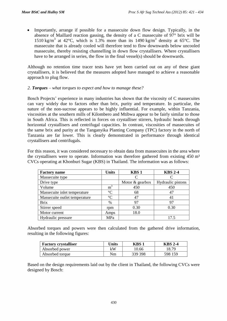
Importantly, arrange if possible for a massecuite down flow design. Typically, in the
absence of Maillard reaction gassing, the density of a C massecuite of 97° brix will be
1510 kg/m3 at 42°C, which is 1.3% more than its 1490 kg/m
3 density at 65°C. The
massecuite that is already cooled will therefore tend to flow downwards below uncooled
massecuite, thereby resisting channelling in down flow crystallisers. Where crystallisers
have to be arranged in series, the flow in the final vessel(s) should be downwards.
Although no retention time tracer tests have yet been carried out on any of these giant
crystallisers, it is believed that the measures adopted have managed to achieve a reasonable
approach to plug flow.
2. Torques – what torques to expect and how to manage these?
Bosch Projects’ experience in many industries has shown that the viscosity of C massecuites
can vary widely due to factors other than brix, purity and temperature. In particular, the
nature of the non-sucrose appears to be highly influential. For example, within Tanzania,
viscosities at the southern mills of Kilombero and Mtibwa appear to be fairly similar to those
in South Africa. This is reflected in forces on crystalliser stirrers, hydraulic heads through
horizontal crystallisers and centrifugal capacities. In contrast, viscosities of massecuites of
the same brix and purity at the Tanganyika Planting Company (TPC) factory in the north of
Tanzania are far lower. This is clearly demonstrated in performance through identical
crystallisers and centrifugals.
For this reason, it was considered necessary to obtain data from massecuites in the area where
the crystallisers were to operate. Information was therefore gathered from existing 450 m³
CVCs operating at Khonburi Sugar (KBS) in Thailand. The information was as follows:
Factory name Units KBS 1 KBS 2-4
Massecuite type C C
Drive type Motor & gearbox Hydraulic pistons
Volume m3 450 450
Massecuite inlet temperature °C 68 47
Massecuite outlet temperature °C 47 41
Brix % 97 97
Stirrer speed rpm 0.30 0.30
Motor current Amps 18.0
Hydraulic pressure MPa
17.5
Absorbed torques and powers were then calculated from the gathered drive information,
resulting in the following figures:
Factory crystalliser Units KBS 1 KBS 2-4
Absorbed power kW 10.66 18.79
Absorbed torque Nm 339 398 598 159
Based on the design requirements laid out by the client in Thailand, the following CVCs were
designed by Bosch:
Moor BStC and Hulley SM Proc S Afr Sug Technol Ass (2012) 85: 421 - 434
430
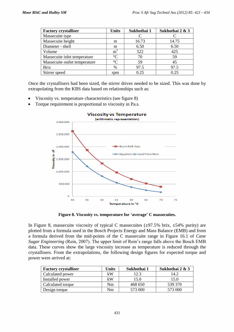
Factory crystalliser Units Sukhothai 1 Sukhothai 2 & 3
Massecuite type C C
Massecuite height m 16.73 14.75
Diameter - shell m 6.50 6.50
Volume m3 522 425
Massecuite inlet temperature °C 70 59
Massecuite outlet temperature °C 59 45
Brix % 97.5 97.5
Stirrer speed rpm 0.25 0.25
Once the crystallisers had been sized, the stirrer drives needed to be sized. This was done by
extrapolating from the KBS data based on relationships such as:
Viscosity vs. temperature characteristics (see figure 8)
Torque requirement is proportional to viscosity in Pa.s.
Figure 8. Viscosity vs. temperature for ‘average’ C massecuites.
In Figure 8, massecuite viscosity of typical C massecuites (±97.5% brix, ±54% purity) are
plotted from a formula used in the Bosch Projects Energy and Mass Balance (EMB) and from
a formula derived from the mid-points of the C massecuite range in Figure 16.1 of Cane
Sugar Engineering (Rein, 2007). The upper limit of Rein’s range falls above the Bosch EMB
data. These curves show the large viscosity increase as temperature is reduced through the
crystallisers. From the extrapolations, the following design figures for expected torque and
power were arrived at:
Factory crystalliser Units Sukhothai 1 Sukhothai 2 & 3
Calculated power kW 12.3 14.2
Installed power kW 15.0 15.0
Calculated torque Nm 468 650 539 370
Design torque Nm 573 000 573 000
Moor BStC and Hulley SM Proc S Afr Sug Technol Ass (2012) 85: 421 - 434
431

Figures 9a, 9b and 9c show the crystallisers at Sukhothai before commissioning.
Figure 9a. Sukhothai crystallisers and reheaters.
Figure 9b. Kavitsu drives. Figure 9c. Reheater detail.
Moor BStC and Hulley SM Proc S Afr Sug Technol Ass (2012) 85: 421 - 434
432

As shown in Figure 9a, the 522 m3 first stage crystalliser (centre, processing the warmest
massecuite) feeds the two 425 m3 crystallisers, one on each side. For commonality of spares,
all three CVCs were given the same drive, the details of which are as follows:
Installed power – 15 kW
Gear ratio – 5732:1
Gearbox rated torque – 700 000 Nm
Gearbox name – Kavitsu
Country of origin – India.
Each 425 m3 crystalliser feeds a reheater (details below), from which the reheated massecuite
is fed directly into the centrifugal feed manifold.
3. Performance – how has actual performance compared with design?
In practice, the crystallisers have been able to achieve better than the design temperature
drops − from 70°C down to 40°C, vs. design of 70°C down to 45°C, with cooling water at the
specified 32°C design temperature. The variable speed drives (VSDs) are configured with
torque limit protection, but have managed to attain the design speeds within the allowable
motor currents. Power readings were taken under two conditions: with cooling in the final
crystallisers to the design of 45°C and with cooling to the maximum attempted of 40°C.
Results are given below.
Factory crystalliser Units Sukhothai 1 Sukhothai 2 & 3
Design cooling Max cooling
Temperature in °C 70 60 60
Temperature out °C 60 45 40
Power absorbed (actual) kW 6.0 8 14
Power absorbed (design) kW 12.3 14.2 -
All powers were measured with rotation at 50 Hz; i.e. at the full design speed. The torques
were thus significantly lower than allowed for, indicating lower massecuite viscosities than
anticipated. It is apparent that, with these massecuites, the same drive would have permitted a
taller first vessel, to give a capacity of 550-600 m3.
Massecuite reheaters
As stated above, the massecuite was designed to be cooled in the Sukhothai crystallisers to
45°C, and in practice has been cooled to 40°C. At these temperatures the massecuite is too
viscous for centrifugation. The reheating specification was to heat the 62 t/h (41 m3/h) of
massecuite to 55°C as rapidly as possible with heating water of ≤59°C, conditions that
minimise the risk of crystal dissolution.
Bosch reheaters, described by Gibbon and Moor (2002), were selected for this duty (see
Figure 9c). From the reheater design program and assuming a conservative heat transfer
coefficient of 16 W/m2.K, it was calculated that a heating surface of 2300 m
2 would be
required. Although this could have been provided in a single reheater, there was concern
about the flow resistance in transferring 41 m3/h of cooled massecuite into and through a
single unit. It was therefore decided instead to provide two 1163 m2 reheaters, each located
with a short infeed pipe from one of the final crystallisers. These reheaters have an
Moor BStC and Hulley SM Proc S Afr Sug Technol Ass (2012) 85: 421 - 434
433

exceptionally high heating surface/massecuite volume ratio of 48 m2/m
3, which is ideal for
rapid heating with a low water – massecuite ΔT. The viscosity of the reheated massecuite
would be much lower than that into the reheaters, so that the 900 mm diameter outlets from
each of the two reheaters could feed at a comfortable 0.54 m/min into the single 1200 mm
manifold feeding the C centrifugals.
The reheaters have achieved the specified 55°C output temperature, even with 40°C input
massecuite, without excessive head loss.
Conclusion
Designing large process equipment for sugar factories processing up to 50 000 tons cane/day
has presented new challenges. Results from some of 14 continuous pans of 250-300 m3 and a
number of crystallisers of up to 525 m3, confirm that these challenges have been successfully
met.
Acknowledgements
Thanks are due to Wellman in Thailand for their assistance in procuring samples and data for
this paper. The assistance of the SMRI with sugar analyses and photographs is appreciated.
REFERENCES
Cox MGS (2012). Commissioning report, Nakorn Phet 280 m
3 continuous pan. Internal Report, Bosch
Projects.
Getaz MA and Sanders RR (2011). Recent developments in vertical crystallizer design. Proc S Afr
Sug Technol Ass 84: 472-484.
Getaz MA, Journet G, Love DJ and Sanders RR (2007). Some notes on developments in high grade
continuous pan boiling. Proc Int Soc Sug Cane Technol 26: 1680-1684.
Gibbon MJ and Moor BStC (2002). A new compact vertical reheater. Proc S Afr Sug Technol Ass 76:
400-410.
Graham WS and Radford DJ (1976). A preliminary report on a continuous C pan. Proc S Afr Sug
Technol Ass 51: 107-111.
Greenfield MS (1984). The selection of a novel crystalliser drive. Proc S Afr Sug Technol Ass 58:
102-110.
Moor BStC (2007). Successful innovation: results from the Bosch continuous pan. Proc Int Soc Sug
Cane Technol 26: 1669-1675.
Morel du Boil P (1991). The role of oligosaccharides in crystal elongation. Proc S Afr Sug Technol
Ass 65: 171-178.
Morel du Boil P (1995). Cane deterioration – cane deterioration and some processing implications.
Proc S Afr Sug Technol Ass 69: 146-154.
Rein PW (2007). Cane Sugar Engineering. Verlag Dr Albert Bartens KG, Berlin, 768 pp.
Thelwall JCdeC (2000). Features of continuous vacuum pan design. Int Sug J Vol. 102, No. 1224:
630-637.
Vermeulen PLM (2011). Thai Roong Ruang and Ban Rai sugar mills: Report on commissioning of
continuous vacuum pans. PolTec Report, Bosch Projects.
Moor BStC and Hulley SM Proc S Afr Sug Technol Ass (2012) 85: 421 - 434
434