Design of an Embedded Solar Tracking System Based on GPS ... · Keywords: Dual Axis Trackers,...
20
International Journal of Information Technology and Web Engineering, 9(1), 1-20, January-March 2014 1 Copyright © 2014, IGI Global. Copying or distributing in print or electronic forms without written permission of IGI Global is prohibited. ABSTRACT This article presents the design of a reliable, accurate, and easy to install solar dual axis tracking system. The system utilizes the GPS for fixing the time, date and location in terms of longitude and latitude. Approximations having high accuracy of the astronomical equations to represent the declination angle and the equation of time are selected to determine the sun locations needed by the designed tracking system in any chosen location on earth. The proposed system is standalone, accurate, durable, reliable, and cost efficient. Annual energy assessments of the system are also given. Design of an Embedded Solar Tracking System Based on GPS and Astronomical Equations Fawzi M. Al-Naima, Al-Nahrain University, Baghdad, Iraq Ramzy S. Ali, Basrah University, Basrah, Iraq Ahmed J. Abid, Foundation of Technical Education, Baghdad, Iraq Keywords: Dual Axis Trackers, Embedded System, GPS Based System, Microcontroller, Sensorless Tracker, Solar Tracker INTRODUCTION In a step to overcome the limitations of sensor based solar tracking system, a design track- ing strategy is presented which is based on astronomical equations, namely the Equation of Time (ET) and the Declination Angle (δ). This strategy has to take two important fac- tors into consideration. The first one is finding approximation formulas with high accuracy of these equations and figure out the ability of implementing such system which can deal with these rather complicated equations which are based mainly on trigonometric functions. The second factor is how to design a reliable, uninterrupted, accurate and global system that is able to calculate the local time, date and location in terms of longitude and latitude. It follows that the main aim of this paper is to design a global dual axis solar tracker that can process the data with high efficiency and is able to deal with these complicated equations. It also needs to gather the required data from the GPS card and save and manage them in accurate, reliable and uninterrupted real time controller. The Plug in GPS card may be built in the main card or can be plugged in only in the initializing phase (Kalogirou, 2009; Han- kins, 2010). DOI: 10.4018/ijitwe.2014010102
Transcript of Design of an Embedded Solar Tracking System Based on GPS ... · Keywords: Dual Axis Trackers,...

International Journal of Information Technology and Web Engineering, 9(1), 1-20, January-March 2014 1
Copyright © 2014, IGI Global. Copying or distributing in print or electronic forms without written permission of IGI Global is prohibited.
ABSTRACTThis article presents the design of a reliable, accurate, and easy to install solar dual axis tracking system. The system utilizes the GPS for fixing the time, date and location in terms of longitude and latitude. Approximations having high accuracy of the astronomical equations to represent the declination angle and the equation of time are selected to determine the sun locations needed by the designed tracking system in any chosen location on earth. The proposed system is standalone, accurate, durable, reliable, and cost efficient. Annual energy assessments of the system are also given.
Design of an Embedded Solar Tracking System Based on GPS
and Astronomical EquationsFawzi M. Al-Naima, Al-Nahrain University, Baghdad, Iraq
Ramzy S. Ali, Basrah University, Basrah, Iraq
Ahmed J. Abid, Foundation of Technical Education, Baghdad, Iraq
Keywords: Dual Axis Trackers, Embedded System, GPS Based System, Microcontroller, Sensorless Tracker, Solar Tracker
INTRODUCTION
In a step to overcome the limitations of sensor based solar tracking system, a design track-ing strategy is presented which is based on astronomical equations, namely the Equation of Time (ET) and the Declination Angle (δ). This strategy has to take two important fac-tors into consideration. The first one is finding approximation formulas with high accuracy of these equations and figure out the ability of implementing such system which can deal with these rather complicated equations which
are based mainly on trigonometric functions.The second factor is how to design a reliable, uninterrupted, accurate and global system that is able to calculate the local time, date and location in terms of longitude and latitude.
It follows that the main aim of this paper is to design a global dual axis solar tracker that can process the data with high efficiency and is able to deal with these complicated equations. It also needs to gather the required data from the GPS card and save and manage them in accurate, reliable and uninterrupted real time controller. The Plug in GPS card may be built in the main card or can be plugged in only in the initializing phase (Kalogirou, 2009; Han-kins, 2010).DOI: 10.4018/ijitwe.2014010102

Copyright © 2014, IGI Global. Copying or distributing in print or electronic forms without written permission of IGI Global is prohibited.
2 International Journal of Information Technology and Web Engineering, 9(1), 1-20, January-March 2014
RADIATION INCIDENT ANGLE
The power incident on a PV module depends not only on the power contained in the sunlight, but also on the angle between the module and the sun. When the absorbing surface and the sunlight are perpendicular to each other, the power density on the surface is equal to that of the sunlight (in other words, the power density will always be at its maximum when the PV module is perpendicular to the sun).
However, as the angle between the sun and a fixed surface is continually changing, the power density on a fixed PV module is less than that of the incident sunlight. The percent-age system tracking efficiency ηTas a function of the incidence angle α is defined by (ηT = 100sin (α) %). Figure 1 displays the calculated efficiencies at different values of α.
The lower Sun angle (45°) causes the radia-tion to be received over a much larger surface area. This surface area is approximately 40% greater than the area covered by an angle of 90°. The lower angle also reduces the intensity of the incoming rays by about 30%.
GPS RECEIVER
Presently, the GPS is fully operational and meets the criteria established in the 1960s for an optimum positioning system. The system provides accurate, continuous, worldwide, three-dimensional position and velocity infor-mation to users with the appropriate receiving
equipment, and disseminates a form of Coor-dinated Universal Time (UTC). The satellite constellation nominally consists of 24 satellites arranged in 6 orbital planes with 4 satellites per plane. A worldwide ground control/monitoring network monitors the health and status of the satellites (Kaplan & Hegarty, 2006).
The Fastrax UP500 module supports en-hanced navigation accuracy by utilizing WAAS/EGNOS corrections. The Fastrax UP500 mod-ule provides complete signal processing from the internal antenna to the serial data output in NMEA messages. A Pulse per Second (PPS) signal output is available for accurate timing applications.
The Fastrax UP500 module interfaces to the customer’s application via one serial port, which uses CMOS voltage levels. If RS232 signal levels are required, there is a variant of Fastrax UP500 available with on-board CMOS-to-RS232 level converter. PPS output is available from the module with CMOS levels. This E-block allows investigation of the global positioning system used in modern satellite navi-gation equipment. The board allows GPS to be added to microcontrollers and other processors that do not have GPS peripherals embedded into them. The board uses a state of the art UP500 GPS module from Fastrax.
The GPS module uses multiple orbiting satellites to calculate its position. Once an initial position has been acquired the GPS re-ceiver continues to send position information directly to the microcontroller ready for further processing. The GPS is also capable of stream-
Figure 1. System tracking efficiencies

Copyright © 2014, IGI Global. Copying or distributing in print or electronic forms without written permission of IGI Global is prohibited.
International Journal of Information Technology and Web Engineering, 9(1), 1-20, January-March 2014 3
ing universal time and date data (UTC) directly to the microcontroller for use in the specified application (U-Blox Fastrax GPS, 2012).
GPS SENTENCES
There are many sentences transmitted by the GPS but the following information describes the most common NMEA-0183 sentences transmitted by GPS receivers. The NMEA standards shown in Table 1 provide quite a range of sentences, but many are related to non-GPS devices and some others are GPS related but rarely used. NMEA mode is the most recommended for new GPS applications to give maximum compatibility with all GPS receivers. Most GPS receivers also have a binary mode but it is normally best to reserve the use of binary GPS protocols for applications that really require their use, such as those requiring position updates of greater than once per second (Matrix Multimedia, 2012).
The RMC sentence has been adopted in this project because it has all the required information. Details of the following example code ($GPRMC, 092204 .999, A, 4250. 5589, S, 1418.5084, E, 0.00,89.68,211212, *25) are shown in Table 2.
The date is also available in this sentence taking into consideration that when local time is crossing the midnight in local area date should be increment by one day.
Local Standard Time Meridian (LSTM)
The Local Standard Time Meridian (LSTM) is a reference meridian used for a particular time zone and is similar to the Prime Meridian, which is used for Greenwich Mean Time. The (LSTM) is calculated according to the follow-ing equation:
LSTM =(360°/24)ΔTGMT= (15°) ΔTGMT
where ΔTGMT is the difference between the Lo-cal Time (LT) and the Greenwich Mean Time (GMT) in hours.
Time Correction Factor (TC)
The net Time Correction Factor (in minutes) accounts for the variation of the Local Solar Time (LST) within a given time zone due to the longitude variations within the time zone, and the Equation of Time (ET). It is given by:
TC= 4 (longitude – LSTM) + ET
The factor of 4 minutes comes from the fact that the Earth rotates 1° every 4 minutes.
Local Solar Time (LST)
The Local Solar Time (LST) can be determined from the previous two corrections to adjust the local time (LT):
Table 1. Common NMEA sentence types
Common NMEA Sentence types
Sentence Description
$GPGGA Global positioning system fixed data
$GPGLL Geographic position - latitude / longitude
$GPGSA GNSS DOP and active satellites
$GPGSV GNSS satellites in view
$GPRMC Recommended minimum specific GNSS data
$GPVTG Course over ground and ground speed

Copyright © 2014, IGI Global. Copying or distributing in print or electronic forms without written permission of IGI Global is prohibited.
4 International Journal of Information Technology and Web Engineering, 9(1), 1-20, January-March 2014
LST = LT+ (TC/60)
Note that angles in degrees and minutes may be converted into regular form as follows:
Angle° = Deg. + (Min. /60) + (Sec. /3600)
TRACKER STRUCTURE
The adopted mechanical structure and the track-ing technique are shown in Figure 2. It is based on full tracking with tilt and polar angles. The system uses two actuators with built in reed sensors (Al-Naima, Ali, & Abid, Design and implementation of a smart dual axis sun tracker based on astronomical equations, 2012). The figure shows the design structure which can carry up to six solar panels (130 watts, 11 kg each) as a static load taking into consideration the dynamic loads such as wind and rain.
ASTRONOMICAL EQUATIONS
The proposed system tracks the sun based on astronomical equations. These equations are important to calculate and manage the tracking system. These equations are described in many forms with different accuracies in comparison with the reference published astronomical tables. The basic two of these equations needed for sun tracking purposes are the Declination Angle (δ), and the Equation of Time (EoT).
The Declination Angle
There exist many approximating formulas in the literature to describe the declination angle δ as a function of the day of the year (NDY). Table 3 lists five of these recommended formulas with Average Absolute Error (AAE), Max Absolute Error (MAE) and the Sum of Squared Error (SSE), see the Appendix. Figure 3 shows the calculated absolute error for these declination
Table 2. Recommended minimum specific GNSS data
RMC
Field Example Comments
Sentence ID $GPRMC
UTC Time 092204.999 hhmmss.sss
Status A A =Valid, V =Invalid
Latitude 4250.5589 ddmm.mmmm
N/S Indicator S N = North, S = South
Longitude 14718.5084 dddmm.mmmm
E/W Indicator E E = East, W = West
Speed over ground 0.00 Knots
Course over ground 0.00 Degrees
UTC Date 211212 DDMMYY
Magnetic variation Degrees
Magnetic Variation
E = East, W = West
Checksum *25
Terminator CR/LF

Copyright © 2014, IGI Global. Copying or distributing in print or electronic forms without written permission of IGI Global is prohibited.
International Journal of Information Technology and Web Engineering, 9(1), 1-20, January-March 2014 5
angle equations compared with the published tabulated values for the year (2012). It can be seen from Table 3 and Figure 3 that the best approximation is given by the formula number 5 which was adopted for this tracking strategy.
The Equation of Time (EoT)
As in the case of the declination angle, there are many approximation formulas for the determi-nation of the EoT as a function of the day of the year. Table 4 lists four of these recommended
Figure 2. Tracker structure
Table 3. Approximation formulas for the declination angle
Item Formula AAE MAE SSE
1. δ1 = 23.45 sin[(360/365)(NDY+284)] 0.5345 1.6964 213.069
2. δ2 = 23.45 sin[(360/365)(NDY–80)] 0.7281 2.0757 351.514
3. δ3 = asin{0.39795 cos[0.98563(NDY- 173)]} 0.4193 1.2303 124.178
4. δ4 = 23.47 sin[(360/365) (NDY+284)] 0.5389 1.7042 214.945
5. δ5 = 0.33281 – 22.984cosN + 3.7872sinN – 0.3499cos2N + 0.03205sin2N – 0.1398cos3N + 0.07187sin3N
Where N = (360/365)NDY0.2753 0.5760 40.834

Copyright © 2014, IGI Global. Copying or distributing in print or electronic forms without written permission of IGI Global is prohibited.
6 International Journal of Information Technology and Web Engineering, 9(1), 1-20, January-March 2014
formulas with their respective values of AAE, MAX and SSE. Figure 4 shows the calculated absolute error for these four equations compared with the published tabulated values for the year (2012). The results displayed in Table 4 and Figure 4 concluded the adoption of formula number 4 as being the best approximation for the EoT.
Sunrise and Sunset Times
Let Hrs be the time between the local noon and the sunrise time and Hss be the time from the local noon to the sunset time, then, for a given latitude (L):
Hss= − Hrs = acos(− tan (L) tan (δ))/15Local noon = 12 – EoT /60
Sunrise Time = Local noon – HrsSunset Time = Local noon + HssDay Length = 2Hss
THEORY OF TRACKING
There are two important equations that describe the dual axis, namely, Tilt Angle (TA) and Polar Angle (PA) as shown in Figure 5.
Local Time (LT) = GMT + Longitude /15o
TA= 90o − ABS (L− δ)PA (LT) = 90o − (Local noon −Local Time) /4
It follows that, the Start Tracking Angle (STTA) and Stop Tracking Angle (SPTA) in degrees may be defined as:
Figure 3. The absolute error for declination angle formulas
Table 4. Approximation formulas for the equations of time
No. Formula AAE MAE SSE
1 EoT1 = 9.87sin2B – 7.53cosB – 1.5sinB where B=360*(NDY-81)/365) 0.5367 2.5918 183.2845
2EoT2 = - 9sin[2(NDY-1)] -5 for NDY ≤ 100
EoT2 = 5sin[(NDY-100)/(0.395)] -1 for 100 <NDY < 242 EoT2 = 18.6sin[(NDY-242)/(0.685)] – 2.5 for NDY ≥ 242
0.5618 2.2463 166.6658
3 EoT3 = 12 +0.123sinX – 0.0043cosX + 0.1538sin2X + 0.0608cos2X Where X = (NDY -1)(360/365.242) 0.3389 1.8751 78.6173
4EoT4 = 0.00037 – 7.3464sinX + 0.43177cosX – 9.3893sin2X – 3 . 1 6 5 c o s 2 X – 0 . 2 4 4 9 8 s i n 3 X + 0 . 0 7 2 7 2 c o s 3 X Where X = (360/365)NDY
0.3047 1.5856 67.2716

Copyright © 2014, IGI Global. Copying or distributing in print or electronic forms without written permission of IGI Global is prohibited.
International Journal of Information Technology and Web Engineering, 9(1), 1-20, January-March 2014 7
STTA = PA (Sunrise + Hold Time)SPTA = PA (Sunset − Hold Time)
Where, Hold Time is a chosen time to hold tracking after sunrise or before sunset since the sun irradiance is low at these times. The Sun location depends directly on three important factors; time, date and location which are nec-essary to find the sun position.
It is clear that the accuracy in determining these factors will be reflected in the accuracy of the sun position.
Figure 4. The absolute error for the equation of time formulas
Figure 5. The system tilt and polar angles

Copyright © 2014, IGI Global. Copying or distributing in print or electronic forms without written permission of IGI Global is prohibited.
8 International Journal of Information Technology and Web Engineering, 9(1), 1-20, January-March 2014
SOFTWARE ALGORITHM
Data Acquisition
The GPS sends different types of sentences with different data or arrangement but there are common things between these sentences. Most of these sentences start with “$” followed by “GP” in the sentence ID. The other common things is that the sentences have a “*” before
the checksum at the end of the sentence. Figure 6 shows part of the flowchart related to data acquisition from the GPS.
To catch the beginning of any sentence it is required to read the string characters one by one until the character “$”is reached. Then, it is required to read the next five characters which represent the sentence ID. This ID gives the receiver a complete idea about the structure of the sentence. After that it is required to figure
Figure 6. Data acquisition flowchart

Copyright © 2014, IGI Global. Copying or distributing in print or electronic forms without written permission of IGI Global is prohibited.
International Journal of Information Technology and Web Engineering, 9(1), 1-20, January-March 2014 9
out if this statement will satisfy the system data requirement, since some sentences have no information about the date.
However, the used sentence in this de-sign is RMC which has all the required data, and when the receiver catches this ID it will keep reading the sentence up to the end. The microcontroller checks the validity of the data based on the status of the sentence to decide if it uses these data in this sentence or skipsthem and goes back to read the new update. If this sentence is a valid and has no error relative to the checksum, it will be ready to be used by the system. The required data like the UTC time, date, latitude and longitude are gathered in this part of the algorithm. The microcontroller will then initialize the I2C communication line to start communication with RTC circuit. The step is considered to be the last step in the initializing phase of the RTC and from then on any data required about the time, date or location will be requested from the RTC unit because it manages these data with high precision. The location information will be saved in the free RAM that is available on the same chip. Figure 7 shows the flowchart related to the data management and processing.
Power and Temperature Control
The adopted system is not only driving the solar panel to the exact position facing the sun but it also has a power and temperature measuring and monitoring capabilities. In this phase the system measures and monitors the voltage, current and temperature continuously.
The system measures the voltage and current for maximum power point tracking MPPT, and the voltage measurement gives an indication to the system to freeze the tracker in cloudy days to save the tracking power. The temperature is measured for two reasons. The first is to warn and alarm for overheat in differ-ent levels of temperatures as kind of protection, and the second is for MPPT prediction purposes if required.
Data Management and Driving Control
The system is designed to read the time and date periodically from the RTC and calculate the δ, EoT, TA, PA, STTA, SPTA and all the required data to find the sun location (Al-Naima, Ali, & Abid, Design of a control and data acquisition system for a multi-mode solar tracking farm, 2012).
After calculating the TA and PA the system starts moving the solar panel into the specified position. The system uses DC actuators similar to the one used in moving a satellite dish. Three control signals are sent by the MCU to drive these two actuators. These three signals are (EN, R/L and M1/M2). EN is responsible for switching the power into the actuators, R/L is for switching the polarity for right or left direc-tion and M1/M2 is responsible for choosing the actuator that needs to be driven.
As a feedback signal the design uses the built in reed sensor inside the actuator case with no extra cost. This sensor sends 45 pulses per inch which gives a high accuracy of the system. There is one problem with this sensor that the actuator location can be figured out by counting the number of the transmitting pulses and losing the power may cause to lose the location but this problem has been solved by adopting two techniques. The first is resetting both actuators every time the tracker gets reset which guaran-tees reset the counter, and the second is using the built in flash RAM inside the MCU which keeps the actuator location even with losing power. By the end of the day the MCU returns the solar panel to the STTA of the next day.
Data Management and Driving Control
The design includes a 4x20 LCD screen to monitor data and display warning or alarm if any. The data are displayed in accordance with the type on three pages as shown in Figure 8. These pages can be changed by pressing a Left or Right button. The first page displays time, date and the current TA and PA. The second page

Copyright © 2014, IGI Global. Copying or distributing in print or electronic forms without written permission of IGI Global is prohibited.
10 International Journal of Information Technology and Web Engineering, 9(1), 1-20, January-March 2014
displays the astronomical data which include the latitude, declination angle, equation of time,
Figure 7. Data management and processing flowchart

Copyright © 2014, IGI Global. Copying or distributing in print or electronic forms without written permission of IGI Global is prohibited.
International Journal of Information Technology and Web Engineering, 9(1), 1-20, January-March 2014 11
hold time, STTA and SPTA. The last page dis-plays temperature, voltage, current and power.
HARDWARE SPECIFICATIONS
The design includes an ATmega32 micro-controller to manage, control and monitor all the circuits (Dhananjay, 2001), see Figure 9 . The ATmega 32 is a low-power CMOS 8-bit microcontroller based on the AVR enhanced RISC architecture.
All the data will be monitored on the LCD screen. The MCU also controls the driving circuit to control the actuators. The used MCU managed all the attached circuits to read data from the GPS, calculate the angles required to track the sun’s location, and measure the voltage and current to find the produced power from the solar panels.
• GPS Card: ATmega 32 has a built in Universal Synchronous and Asynchronous serial Receiver and Transmitter (USART). This USART is a highly flexible serial communication device. The MC reads the received data from the GPS card through RXD (PD0) with a baud rate of 9600 kbps. This MC has the ability to interrupt by Rx signal and that is important for syn-chronization purposes. The used Card has MAX3002 for voltage shifting. The Card photo is shown in Figure 10.
• RTC: The used Real Time Controller (DS1307) has Real time clock to count seconds, minutes, hours, the date of the month, month, day of the week, and year with leap year compensation valid up to 2100, 56 bytes nonvolatile RAM for data storage, 2-wire serial interface, Programmable square wave output signal,
Figure 8. LCD data arrangement

Copyright © 2014, IGI Global. Copying or distributing in print or electronic forms without written permission of IGI Global is prohibited.
12 International Journal of Information Technology and Web Engineering, 9(1), 1-20, January-March 2014
Automatic power-fail detect and switch circuitry, Consumes less than 500 ha in battery backup. The MC communicates with RTC via I2C (SDA & SCL) as shown in Figure 11.
• RST: This is used to reset the controller and load the data from the GPS to RTC. This is because the design has a standalone time controller which needs to be initialized by the GPS for time and data and to store the location data.
• Keypad: A 4x4 matrix keypad is used to enter data but it is optional.
• LPF: Low Pass Filter is used for ADC noise reduction.
• Monitoring Control of the LCD screen: These are two left and right switches used to slide the LCD view left or right.
• Actuator Driving Circuit: This is re-sponsible for driving the power into the specified actuator with specified polarity to move the actuator in and out as shown in Figure 12.
• Sensor Signal Driving and Conditioning: This circuit is responsible for driving the EN signal into the Reed Sensors condition-ing the received signal to the MC.
• LCD: The LCD screen is a 4x20 (LM044L) characters controlled by the MC via port D.
• Temperature Sensor: LM35dz (–50 to 150) sensor is used to measure temperature for the controlling purpose. The LM35 series are precision integrated-circuit temperature sensors, whose output volt-age is linearly proportional to the Celsius temperature.
• Voltage Scaling: This circuit is used to scale the solar panel voltage from any level in 0-5 Volt level to be compatible with MC ADC.
• High Side Current Sensor: The INA168 is a high-side, unipolar, current shunt moni-tors. Wide input common-mode voltage range, low quiescent current. The device converts a differential input voltage to a cur-rent output. This current is converted back to a voltage with an external load resistor to set any gain from 1 to over 100. This sensor uses a shunt resistor (Rsh=0.0001Ω) which is a piece of the main cable with specified length based on its resistivity, see Figure 13.
Figure 9. Block diagram for the main controller

Copyright © 2014, IGI Global. Copying or distributing in print or electronic forms without written permission of IGI Global is prohibited.
International Journal of Information Technology and Web Engineering, 9(1), 1-20, January-March 2014 13
The photos in Figure 14 show the mechanical structure and the control box of the system.
ENERGY ASSESSMENTS
Energy Consumed by Polar Actuator
The range of daily tracking in degrees is given by:
TR = SPTA – STTA
The system is designed to push the actuator shaft 3mm per degree, (Shaft length / Tracking range), by speed equals to 4.2 mm per second, and power of 9.6 W in accordance with the actuator design specifications.
At this stage it is required to introduce the DailyTracker Running Time (DTRT), which is defined as the time spent to move the panel from STTA to SPTA per one day and is given by:
DTRT = TR*3/4.2 =TR/1.4
By adding up the calculated values of DTRT from 1st January to 31st December for Holding Time equals two hours, the value of the Annual
Figure 10. GPS board by Matrix Multimedia
Figure 11. RTC DS1307 Pin configuration

Copyright © 2014, IGI Global. Copying or distributing in print or electronic forms without written permission of IGI Global is prohibited.
14 International Journal of Information Technology and Web Engineering, 9(1), 1-20, January-March 2014
TRT in Baghdad (ATRT) is found to be, (ATRT≈ 31232 Sec). Note that this value of ATRT was taken from the ASTF report (Al-Naima F. M., An FPGA Based Stand-Alone Solar Tracking
System, 2012). Since the tracker moves the panel back at the end of a day for the next day STTA, then the overall value of ATRT should be multiplied by two (i.e., 31232 x 2 = 62464
Figure 12. Actuator driving circuit
Figure 13. Voltage scaling and current sensing circuits

Copyright © 2014, IGI Global. Copying or distributing in print or electronic forms without written permission of IGI Global is prohibited.
International Journal of Information Technology and Web Engineering, 9(1), 1-20, January-March 2014 15
Sec), it follows that the total annual consumed energy is equal to (9.6 W * 62464 sec) ≈ 599.6 kJ/year.
Energy Consumed by Tilt Actuator
This actuator runs in any location from the winter solstice (WS) to the summer solstice (SS) then goes back to the WS in one year, and the shaft moves 5mm/Deg with a speed of 4.5 mm/Sec.
TR= SS–WS= 23.45 – (–23.45)= 46.9 Deg. Shaft Pushing length = 46.9 (Deg.)* 5 (mm/
Deg) * 2 = 469 mm. The time required for this = 469/4.5 =104
Sec. Hence, the annual consumed energy is (9.6 * 104 ≈ 1kJ).
It follows that the total annual energy consumed by the two actuators over is ap-proximately equal to:
599.6 kJ + 1 kJ = 600.6 kJ ≈ 0.166 kWh.
Energy Produced by the System
The total day time for the test location in Baghdad is equal to 4379h [10]. This number was determined by finding the sum of the day length of each single day which means that the average day length is equal to 11.99 Hours. To find the effective period of one day, it is required to subtract 4 hours per day (two after sunrise and two before the sunset). Hence, the Effec-tive average Day Time =11.99 – 4= 7.99h≈ 8h (Al-Naima F. M., An FPGA Based Stand-Alone Solar Tracking System, 2012).
The average energy produced by the system in one day is equal to the solar power produced by the panels times the average day length. The system consists of 6 panels, 130 W each, it follows that the estimated annual produced energy E in kWh is given by:
E = 6*130*8*365 ≈ 2277.6 kWh
Note that all the above calculations were based on 1.0 k W/m2, according to the testing data. But according to the test place in Baghdad
Figure 14. System mechanical structure and control box
Copyright © 2014, IGI Global. Copying or distributing in print or electronic forms without written permission of IGI Global is prohibited.
16 International Journal of Information Technology and Web Engineering, 9(1), 1-20, January-March 2014
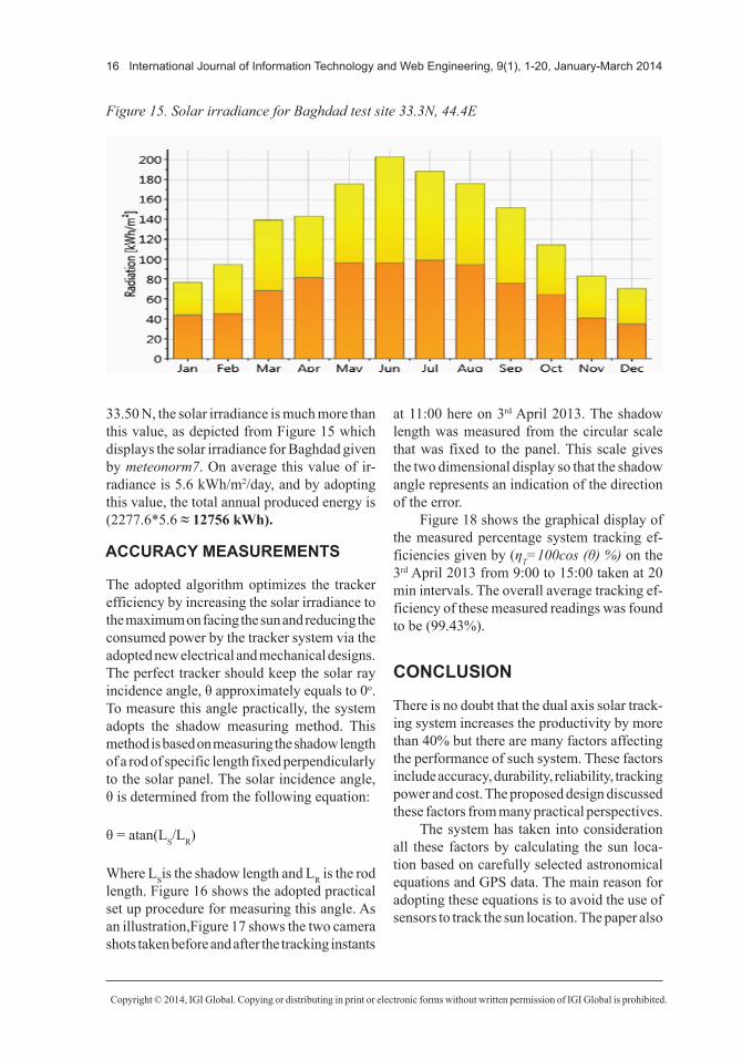
33.50 N, the solar irradiance is much more than this value, as depicted from Figure 15 which displays the solar irradiance for Baghdad given by meteonorm7. On average this value of ir-radiance is 5.6 kWh/m2/day, and by adopting this value, the total annual produced energy is (2277.6*5.6 ≈ 12756 kWh).
ACCURACY MEASUREMENTS
The adopted algorithm optimizes the tracker efficiency by increasing the solar irradiance to the maximum on facing the sun and reducing the consumed power by the tracker system via the adopted new electrical and mechanical designs. The perfect tracker should keep the solar ray incidence angle, θ approximately equals to 0o. To measure this angle practically, the system adopts the shadow measuring method. This method is based on measuring the shadow length of a rod of specific length fixed perpendicularly to the solar panel. The solar incidence angle, θ is determined from the following equation:
θ = atan(LS/LR)
Where LSis the shadow length and LR is the rod length. Figure 16 shows the adopted practical set up procedure for measuring this angle. As an illustration,Figure 17 shows the two camera shots taken before and after the tracking instants
at 11:00 here on 3rd April 2013. The shadow length was measured from the circular scale that was fixed to the panel. This scale gives the two dimensional display so that the shadow angle represents an indication of the direction of the error.
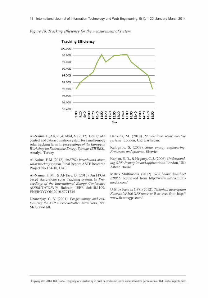
Figure 18 shows the graphical display of the measured percentage system tracking ef-ficiencies given by (ηT=100cos (θ) %) on the 3rd April 2013 from 9:00 to 15:00 taken at 20 min intervals. The overall average tracking ef-ficiency of these measured readings was found to be (99.43%).
CONCLUSION
There is no doubt that the dual axis solar track-ing system increases the productivity by more than 40% but there are many factors affecting the performance of such system. These factors include accuracy, durability, reliability, tracking power and cost. The proposed design discussed these factors from many practical perspectives.
The system has taken into consideration all these factors by calculating the sun loca-tion based on carefully selected astronomical equations and GPS data. The main reason for adopting these equations is to avoid the use of sensors to track the sun location. The paper also
Figure 15. Solar irradiance for Baghdad test site 33.3N, 44.4E

Copyright © 2014, IGI Global. Copying or distributing in print or electronic forms without written permission of IGI Global is prohibited.
International Journal of Information Technology and Web Engineering, 9(1), 1-20, January-March 2014 17
gave critical assessments of the annual energy production of the system.
REFERENCES
Al-Naima, F., Ali, R., & Abid, A. (2012). Design and implementation of a smart dual axis sun tracker based on astronomical equations. In Proceedings of the European Workshop on Renewable Energy Systems(EWRES), Antalya, Turkey.
Figure 16. Solar ray incidence angle calculation method
Figure 17. Camera shots for incident angle measuring technique before and after tracking
Copyright © 2014, IGI Global. Copying or distributing in print or electronic forms without written permission of IGI Global is prohibited.
18 International Journal of Information Technology and Web Engineering, 9(1), 1-20, January-March 2014
Al-Naima, F., Ali, R., & Abid, A. (2012). Design of a control and data acquisition system for a multi-mode solar tracking farm. In proceedings of the European Workshop on Renewable Energy Systems (EWRES), Antalya, Turkey.
Al-Naima, F. M. (2012). An FPGA based stand-alone solar tracking system. Final Report, ASTF Research Project No.134-10, UAE.
Al-Naima, F. M., & Al-Taee, B. (2010). An FPGA based stand-alone solar Tracking system. In Pro-ceedings of the International Energy Conference (ENERGYCON10). Bahrain: IEEE. doi:10.1109/ENERGYCON.2010.5771735
Dhananjay, G. V. (2001). Programming and cus-tomizing the AVR microcontroller. New York, NY: McGraw-Hill.
Hankins, M. (2010). Stand-alone solar electric systems. London, UK: Earthscan.
Kalogirou, S. (2009). Solar energy engineering: Processes and systems. Elsevier.
Kaplan, E. D., & Hegarty, C. J. (2006). Understand-ing GPS: Principles and applications. London, UK: Artech House.
Matrix Multimedia. (2012). GPS board datasheet EB056. Retrieved from http://www.matrixmulti-media.com/
U-Blox Fastrax GPS. (2012). Technical description Fastrax UP500 GPS receiver. Retrieved from http://www.fastraxgps.com/
Figure 18. Tracking efficiency for the measurement of system

Copyright © 2014, IGI Global. Copying or distributing in print or electronic forms without written permission of IGI Global is prohibited.
International Journal of Information Technology and Web Engineering, 9(1), 1-20, January-March 2014 19
APPENDIX
The SSE over the 365 days of the year is defined as
SSE Y Y ei
ai sii
= −( ) == =∑ ∑1
3652
1
3652
WhereYai is the value of EoT or DA obtained at true noonon the ith day of the year and Ysi is the value of EoT or δ obtained from the proposed spline function at the ith day of the year.The MAE over 365 day is defined as the largest absolute error over the whole year:
MAE MAX e ii= ≤ ≤1 365 .
The AAE is given by
AAEe
i= =∑ 1
365 2
365

Copyright © 2014, IGI Global. Copying or distributing in print or electronic forms without written permission of IGI Global is prohibited.
20 International Journal of Information Technology and Web Engineering, 9(1), 1-20, January-March 2014
Fawzi M. Al-Naima received the degrees of BSc (First Class Honors), and PhD in Electrical Engineering from Newcastle University, UK in 1971 and 1976 respectively. He worked as a Lecturer and Associate Professor in Al-Rasheed College of Engineering, Baghdad, Iraq from 1977 to 1989. He has been with the College of Engineering, Al-Nahrain University, Baghdad, Iraq since1989. Professor Al-Naima published more than 70 research papers in national and international journals and conferences. He is the co-author of a book on the analysis of large circuits published by an international publisher in USA. He is also the co-author of four chapters in four books published by international science publishers. Prof. Al-Naima current research interests include computer aided design of large circuits, analog and digital signal pro-cessing, solar tracking system, and smart home energy managements. Professor Al-Naima is a Life Fellow Member of the IETE, India since 1999, and a senior member of IEEE.
Ramzy S. Ali Al-Waily received the BSc and MSc degrees in Electrical Engineering and Control & Comput-ers Engineering from University of Basrah, Basrah, Iraq in 1985 and 1989 respectively. Also received the PhD degree in Control & Systems from the Saint-Petersburg State Polytechnic University, Russia in 2003. He is currently an Assistant professor with University of Basrah. His teaching interests include Intelligent Control Systems, Robust Control Systems, Microprocessor & Microcontrollers and Industrial Automation. He is currently serving as a secretary editor of Basrah Journal for Engineering Sciences and an Editor of International Journal of Advancements in Computing Technology (IJACT). His research interests include Intelligent Control of Robotics, Computational Intelligence, Chaos & Nonlinear dynamics, Renewable electrical energy systems, and PLC applications in industrial and engineering education.
Ahmed J. Abid was born in Samawah, Iraq in 1980. He received a BSc and MSc degrees from the Depart-ment of Electronic Engineering in 2002 and 2005 respectively, from the University of Technology, Iraq. Since 2006, he has been with the Foundation of Technical Education, Iraq as a lecturer. He is currently a PhD candidate in the Department of Electrical Engineering, University of Basrah. His current research interests are solar photovoltaic farm, renewable energy, energy management, power line communication and embedded system design.