Design of an Active-Assistance Balancing Mechanism for a Bicycle
74
Project Code: TP1 MQP IBD0 Design of an Active-Assistance Balancing Mechanism for a Bicycle A Major Qualifying Project Report Submitted to The Faculty of the Worcester Polytechnic Institute In partial fulfillment of the requirements for the Degree of Bachelor of Science in Robotics Engineering by Sam Kaplan Aaron Fineman Approved: Dr Taskin Padir
Transcript of Design of an Active-Assistance Balancing Mechanism for a Bicycle

Project Code: TP1 MQP IBD0
Design of an Active-AssistanceBalancing Mechanism for a Bicycle
A Major Qualifying Project Report
Submitted to The Faculty
of the
Worcester Polytechnic Institute
In partial fulfillment of the requirements for the
Degree of Bachelor of Science in
Robotics Engineering
by
Sam Kaplan Aaron Fineman
Approved:
Dr Taskin Padir

Abstract
The goal of this project is to design and build a prototype self balancing bicycle for
use as a teaching tool for someone learning to ride a bicycle and as means for a disabled
person to ride a bicycle who would otherwise not be able to do so. The project consists
of a research phase in which similar systems have been investigated to help determine
a sensible design approach and to establish appropriate design specifications; a design
phase in which a prototype was designed to meet the aforementioned specifications;
and a construction phase, in which the prototype was built and tested.
This document contains:
• An overview of prior art related to the development of a self balancing bicycle for
use by people not capable of riding a two wheeled bicycle unassisted either due
to inexperience or disability
• A list of specifications and requirements for a prototype of such a bicycle, as well
as a list of specifications an requirements for a marketable version of the finished
product
• A summary of the development of two separate designs, a gyroscopic flywheel
based design and an actuated support arm design as well as the principles of
operation behind each design
• A detailed description of the built prototype and an explanation of the selection
process for the components used in the product
• A report on the performance of the prototype
• A Comparison of the two different designs, and a comparison of the prototype to
the prior art described in the report
• Suggestions for future work to develop the product past the prototype phase
1

Contents
1 Introduction 7
1.1 Passive Balance Systems . . . . . . . . . . . . . . . . . . . . . . . . . . . . . 8
1.1.1 Training Wheels . . . . . . . . . . . . . . . . . . . . . . . . . . . . . . 8
1.1.2 Gyrowheel . . . . . . . . . . . . . . . . . . . . . . . . . . . . . . . . . 9
1.2 Active Balance Systems . . . . . . . . . . . . . . . . . . . . . . . . . . . . . 10
1.2.1 Gyro-Stabilized Monorail . . . . . . . . . . . . . . . . . . . . . . . . . 10
1.2.2 Gyrover . . . . . . . . . . . . . . . . . . . . . . . . . . . . . . . . . . 12
1.2.3 Ghostrider . . . . . . . . . . . . . . . . . . . . . . . . . . . . . . . . . 12
1.2.4 Murata Boy . . . . . . . . . . . . . . . . . . . . . . . . . . . . . . . . 13
1.3 Report Organization . . . . . . . . . . . . . . . . . . . . . . . . . . . . . . . 15
2 Project Specifications and Requirements 16
3 Methodology 17
3.1 Development of a Gyroscopic Balance System . . . . . . . . . . . . . . . . . 17
3.2 Development of an Actuated Arm Support System . . . . . . . . . . . . . . . 20
3.3 Development of Balance Strategies Using the Actuated Arm Support System 23
3.3.1 Strategy 1: Maintaining Constant Contact with the Ground . . . . . 23
3.3.2 Strategy 2: Tilt Angle Correction at a Threshold . . . . . . . . . . . 23
3.3.3 Strategy 3: Tilt Dampening . . . . . . . . . . . . . . . . . . . . . . . 23
3.4 Chassis Subsystem . . . . . . . . . . . . . . . . . . . . . . . . . . . . . . . . 24
3.5 Actuation Subsystem . . . . . . . . . . . . . . . . . . . . . . . . . . . . . . . 26
3.6 Computation Subsystem . . . . . . . . . . . . . . . . . . . . . . . . . . . . . 26
3.6.1 Processing System . . . . . . . . . . . . . . . . . . . . . . . . . . . . 26
3.6.2 Software Development . . . . . . . . . . . . . . . . . . . . . . . . . . 28
3.7 Sensing Subsystem . . . . . . . . . . . . . . . . . . . . . . . . . . . . . . . . 29
3.7.1 Separate Sensors: MEMS Accelerometer and Solid-State Gyroscope . 29
3.7.2 Single Sensor: Inclinometer . . . . . . . . . . . . . . . . . . . . . . . 31
3.8 Electrical Integration Subsystem . . . . . . . . . . . . . . . . . . . . . . . . . 31
3.8.1 System Power Integration . . . . . . . . . . . . . . . . . . . . . . . . 32
3.8.2 System Input/Output Signal Integration . . . . . . . . . . . . . . . . 33
2

4 Results 37
4.1 Data Collection and System Validation . . . . . . . . . . . . . . . . . . . . . 42
4.2 Status of Prototype Specification and Requirement Compliance . . . . . . . 46
5 Discussion 47
5.1 Marketability . . . . . . . . . . . . . . . . . . . . . . . . . . . . . . . . . . . 47
6 Conclusions 49
7 Future Work 50
7.1 Designing for Onboard Power Storage . . . . . . . . . . . . . . . . . . . . . . 50
7.2 Designing for Modularity . . . . . . . . . . . . . . . . . . . . . . . . . . . . . 51
7.3 Designing for Safety . . . . . . . . . . . . . . . . . . . . . . . . . . . . . . . 52
References 53
A Requirements 54
A.1 Prototype . . . . . . . . . . . . . . . . . . . . . . . . . . . . . . . . . . . . . 54
A.2 Final Product . . . . . . . . . . . . . . . . . . . . . . . . . . . . . . . . . . . 56
B Budget 58
C API 59
D PIC32 Datasheet 61
E UBW32 Schematic 66
F CAD Models 68
G PID Control Loop 71
3

List of Figures
1 Inverted pendulum example. . . . . . . . . . . . . . . . . . . . . . . . . . . . 7
2 Polygon of Stability with training wheels. . . . . . . . . . . . . . . . . . . . . 9
3 Gyrobike’s Gyrowheel attached to a standard bicycle. . . . . . . . . . . . . . 10
4 The gyro-stabilized monorail travels above the track, rather than underneath. 11
5 A diagram showing the positioning of the gyroscopes inside the monorail car. 11
6 The Gyrover uses it’s chasis as a wheel. . . . . . . . . . . . . . . . . . . . . . 12
7 The Ghostrider Motorcycle. . . . . . . . . . . . . . . . . . . . . . . . . . . . 13
8 Murata Boy’s flywheel embedded in it’s chest. . . . . . . . . . . . . . . . . . 14
9 The flywheel is mounted directly behind the seat. . . . . . . . . . . . . . . . 17
10 Rotation axes of the flywheel gimbal. . . . . . . . . . . . . . . . . . . . . . . 18
11 Variables used in representing the motion of the system. . . . . . . . . . . . 18
12 Illustration of the system. . . . . . . . . . . . . . . . . . . . . . . . . . . . . 21
13 Motion of the arms. . . . . . . . . . . . . . . . . . . . . . . . . . . . . . . . . 21
14 Variables used in representing the motion of the system. . . . . . . . . . . . 22
15 Mounting points on a standard bicycle. . . . . . . . . . . . . . . . . . . . . . 25
16 Delta backpack rack, used to support the system. . . . . . . . . . . . . . . . 25
17 UBW32 development board . . . . . . . . . . . . . . . . . . . . . . . . . . . 28
18 Schematic diagram demonstrating the control loop. . . . . . . . . . . . . . . 30
19 Flowchart of the electrical subsystems. . . . . . . . . . . . . . . . . . . . . . 32
20 Schematic of the electrical subsystem. . . . . . . . . . . . . . . . . . . . . . . 34
21 The completed prototype. . . . . . . . . . . . . . . . . . . . . . . . . . . . . 38
22 Rear of the system with testing arms attached. . . . . . . . . . . . . . . . . . 39
23 The system mounted to the Delta bicycle rack. . . . . . . . . . . . . . . . . . 40
24 The actuation subsystem with testing arms attached. . . . . . . . . . . . . . 41
25 Calculated and measured arm position over time. . . . . . . . . . . . . . . . 42
26 Error between measured arm position and calculated required arm position
over time. . . . . . . . . . . . . . . . . . . . . . . . . . . . . . . . . . . . . . 43
27 Desired and actual arm positions over time. . . . . . . . . . . . . . . . . . . 44
28 PID-driven PWM motor control signal over time. . . . . . . . . . . . . . . . 44
29 Bicycle tilt angle over time. . . . . . . . . . . . . . . . . . . . . . . . . . . . 45
30 Measured-desired arm position over time. . . . . . . . . . . . . . . . . . . . . 45
4
31 UBW32 Schematic . . . . . . . . . . . . . . . . . . . . . . . . . . . . . . . . 67
32 Isometric view of system. . . . . . . . . . . . . . . . . . . . . . . . . . . . . . 68
33 Rear view of system. . . . . . . . . . . . . . . . . . . . . . . . . . . . . . . . 69
34 Right side view of system. . . . . . . . . . . . . . . . . . . . . . . . . . . . . 70
5

List of Tables
1 Power Requirements . . . . . . . . . . . . . . . . . . . . . . . . . . . . . . . 33
2 PIC32 Pinout in reference to figure 20 . . . . . . . . . . . . . . . . . . . . . 35
3 Inclinometer Pinout in reference to figure 20 . . . . . . . . . . . . . . . . . . 35
4 H-Bridge Pinout in reference to figure 20 . . . . . . . . . . . . . . . . . . . . 36
5 Amplifier Circtuit Pinout in reference to figure 20 . . . . . . . . . . . . . . . 36
6

1 Introduction
Bicycles are a common form of exercise, recreation and transportation used by billions. They
can also serve to provide physical therapy, as they are a low impact form of exercise that
can train balance, strength, stamina and coordination. Though one may consider riding a
bicycle to be a fairly simple task, this is not the case for many people. This includes young
childeren, adults who have never learned to ride a bicycle, injured people, or people suffering
from developmental or cognitive disabilities. A system that could provide balancing assitance
to a bicycle rider without otherwise affecting the experience of riding a bicycle could provide
great benefit to these groups of individuals. Such a system could be used both as a teaching
tool, and as a physically theraputic device.
This problem of balancing a bicycle is analogous to what is known as the ’inverted
pendulum’ problem. An inverted pendulum is a pendulum which has its mass above its
pivot (figure 1). The pendulum can be anything form a simple mass and rod, to a full
system. While a normal pendulum is stable, an inverted pendulum is inherently unstable,
and must be actively balanced to remain upright [1]. In the case of a bicycle, the bicycle is
a rigid body which can rotate around its contact point with the ground. Although a bicycle
motion has multiple degrees of freedom, the particular type of motion which this project
aims to stabilize is this tilt angle around the point of contact with the ground relative to the
direction of gravity.
Figure 1: Inverted pendulum example.
There are many solutions to the inverted pendulum project that already exist, some
7

of which provide complete stabilization of a system, others of which dampen the motion
of the system enough to allow for human correction of any deviation in tilt angle. These
solutions can be broken up into two groups, one of which can be considered Passive Balance
Systems, and Active Balance Systems. An Active Balance System is defined as a system
which actively senses the tilt angle of the system and provides a corrective force based on
the tilt angle to stabilize the system, whereas a Passive Balance System simply dampens
or mechanically limits the motion of the system without any utilization of a calculated tilt
angle. Active balance systems may either provide complete stabilization for a system or
dampen the motion of the system. Passive Balance Systems can only dampen the motion of
the system.
1.1 Passive Balance Systems
1.1.1 Training Wheels
Training wheels are the most common form of stabilization, passive or active, for a bicycle.
Given the principle that a system is stable if an imaginary line drawn from it’s center of
gravity along the direction of gravity intersects with the convex polygon formed by all points
of contact with the ground [2]. Training wheels work by significantly increasing the width
of this polygon, shown in figure 2. Training wheels have several strengths as a solution
to stabilizing a bicycle. They are very inexpensive, easy to install, and provide acceptable
stability as long as the combined center of gravity of the bicycle and the rider do not extend
past the width of the training wheels. They also do not require any power to operate.
However training wheels are not without their shortcomings. They are for the most part
not adjustable, and while they allow a rider to learn some of the skills needed to ride a two
wheeled bicycle, there is no mechanism for the user to become gradually less dependent on
the training wheels over time; they are either attached to the bicycle or they are not. The
other major disadvantage of training wheels is that they do not provide stability under all
normal use conditions. Any situation in which the rider’s center of gravity extends beyond
the width of the training wheels will result in a failure (the rider falls over), this can happen
during a sharp turn or when traveling over uneven surfaces. These can be considered normal
use cases for a bicycle.
8

Figure 2: Polygon of Stability with training wheels.
http://www.invention.net/gaea.htm Accessed on 04-2010
1.1.2 Gyrowheel
Gyrobike’s Gyrowheel is a quite novel approach to passive stabilization of a bicycle. The
Gyrowheel wheel is a proprietary system in which the front wheel of a bicycle is replaced
by a patented [3] [4] wheel containing an embedded gyroscopic flywheel and battery [5].
This replacement can be seen in figure 3. Because a gyroscope resists angular motion other
than around its spin axis due to the principles of momentum conservation and gyroscopic
precession, the Gyrowheel provides passive stability to the bicycle by damping the motion of
the bicycle as it tilts away from the vertical axis [5]. The Gyrowheel has several strengths.
Like training wheels it is relatively easy to install on a bicycle. The Gyrowheel comes with
varying stability settings; the speed of the embedded gyroscope can be adjusted by the user,
which allows for a gradual transition from dependence on the stability aid, to the ability to
ride a standard two wheeled bicycle, making the Gyrowheel an effective teaching tool. The
Gyrowheel has several shortcomings as well. Because it is a powered system, the Gyrowheel
can only be operated continuously for a finite amount of time before the battery needs to be
recharged. The Gyrowheel also alters the experience of riding a bicycle in ways other than
improving stability due to the fact that the gyroscope also resists angular motion around
the vertical axis, and as such requires more force by the rider to turn the handlebars of the
9

bicycle which may not be ideal for a disabled person or a small child. The Gyrowheel also
dampens angular motion towards the vertical axis as well as away from it, therefore there
is a tradeoff between the increased reaction time given to the user to right the bicycle as it
tilts away from the vertical axis and the increased effort required to right the bicycle once it
tilts away from the vertical axis.
Figure 3: Gyrobike’s Gyrowheel attached to a standard bicycle.
http://www.coolthings.com/gyrowheels-will-replace-bicycle-training-wheels-
could-work-for-unicycles-too/ Accessed on 04-2010
1.2 Active Balance Systems
1.2.1 Gyro-Stabilized Monorail
The Gyro-Stabilized Monorail was a prototype system designed to stabilize a monorail with
a center of gravity above the track, rather than below, as shown in figure 4. The system
made use of a powered gyroscopic flywheel with a horizontal spin axis that was free to
rotate around the vertical axis (figure 5). The system causes torque-induced precession of
the gyroscope by rotating the flywheel around it’s vertical axis using a motor [6]. Since a
spinning gyroscope resists this motion, the reaction torque on the actuating motor, which
is fixed to the monorail car, causes the entire car to rotate around the axis of the monorail
track. Thus actuation of the flywheel can be used to stabilize the entire system.
10

Figure 4: The gyro-stabilized monorail travels above the track, rather than underneath.
http://en.wikipedia.org/wiki/Gyro_monorail Accessed on 04-2010
Figure 5: A diagram showing the positioning of the gyroscopes inside the monorail car.
http://en.wikipedia.org/wiki/Gyro_monorail Accessed on 04-2010
11

1.2.2 Gyrover
The Gyrover is a single wheeled system that is statically unstable, but dynamically stable
[7]. The system is non-holonomic due to it’s inability to move sideways. The entire system is
contained within the wheel itself, which serves as the chassis for the system (figure 6). The
control system for the Gyrover is suspended inside the chassis and is free to rotate around the
spin axis of the wheel. The control system consists of 3 motors, 1 which spins a flywheel to
impart dynamic stability on the system, a second motor which rotates the flywheel and thus
controls the tilt angle of the chassis, and a third motor which directly drives the chassis.
By controlling the tilt angle of the Gyrover the turning radius of the system can also be
controlled to allow for steering.
Figure 6: The Gyrover uses it’s chasis as a wheel.
http://www.cs.cmu.edu/~cyberscout/gyrover.html Accessed on 04-2010
1.2.3 Ghostrider
Developed for the Defense Advanced Research Projects Agency’s (DARPA) Grand Chal-
lenge, an autonomous vehicle competition sponsored by the Department of Defense, the
Ghostrider robot is a fully autonomous riderless motorcycle. The Ghostrider makes use of
stereo video image processing and GPS navigation. To remain upright, the Ghost Rider
uses a 6 axis gyroscope to detect it’s orientation in space as well as to calculate it’s angular
12

velocity acceleration. The gyroscope provides readings for the angular position and velocity
of the roll, pitch, and yaw. Using this information, the Ghostrider maintains an upright
position by actuating the front wheel of the motorcycle to make slight turns as the robot
drives. The acceleration from turning creates a lateral reaction force on the motorcycle
which is utilized to keep the bike upright [8]. The degree of turning required to generate the
necessary balancing force is small enough that it does not inhibit the ability of the robot to
successfully navigate the course. The major shortfall of a steering-based balance system for
a two wheeled vehicle is that as the forward speed of the vehicle decreases, the radius of the
turns necessary to maintain balance must increase to result in an equivalent lateral reaction
force, thus causing the vehicle to weave as it moves forward.
Figure 7: The Ghostrider Motorcycle.
http://blog.xbow.com/xblog/2009/10/index.html Accessed on 04-2010
1.2.4 Murata Boy
Murata Boy is a small bipedal humanoid robot designed to ride a miniature bicycle. The
bicycle ridden by Murata boy is functionally equivalent to a normal bicycle, only scaled down.
The Murata Boy is approximately 20” tall when it is on it’s bicycle. All of the balancing
is performed by the Murata Boy robot through the use of gyroscopic sensors to determine
it’s position and tilt. It balances by accelerating an embedded flywheel, seen in figure 8,
around its spin axis, which is parallel to the direction of forward motion of its bicycle [9]. By
accelerating the flywheel, Murata boy is able to lean slightly to the left or the right. Since
13

the Murata Boy robot is able to detect it’s position and orientation in space, it can keep
it’s center of gravity over it’s bicycles wheels, and thus maintain stability. The Murata Boy
robot represents a stabilization strategy in which rather than making the bicycle itself more
stable, the rider is given assistance in positioning their body in such away as to maintain
balance.
Though this strategy may be useful in teaching the rider proper technique, the manner
in which the Murata Boy adjusts its position would not be effective for a human user, even if
the system could be adapted as a wearable flywheel. Murata Boy is capable of keeping track
of all of it’s parts, and modeling it’s current center of gravity. Since positional correction is
achieved by accelerating a flywheel around it’s spin axis in either the positive or the negative
direction, the system will fail when the motor reaches it’s maximum speed. This would
happen if the rider had a tendency to lean to one side while riding.
Figure 8: Murata Boy’s flywheel embedded in it’s chest.
http://www.technoplusworld.com/robot/robot.html Accessed on 04-2010
14
1.3 Report Organization
This report will next discuss the methodology used to develop a self balancing bicycle,
including the development of two potential design concepts, the development of strategies
to balance a bicycle for a given design concept, and description of the principles behind the
physical, electrical, and computational aspects of the system. Following the methodology,
results will be presented based upon data collected during the operation of the system and
the status of the compliance of the prototype to the specifications set forth in this report.
This report will also include a discussion of the results and suggestions for future work on
the system.
15

2 Project Specifications and Requirements
Specifications and requirements were developed for both the initial prototype of this system,
as well as a fully developed commercial product. These were used to define the scope of
this project. These requirements can be categorized as either strict or loose. The strict
requirements will be evaluated on a ’met’ or ’not met’ basis, and must all be met before
the system can be built at a level of quality that would allow for commercial production.
The loose requirements may or may not be achieved due to design tradeoffs, however, how
close the system comes to meeting these requirements is both a measure of success and of
the quality of the product. In some cases, loose requirements may define a minimum level of
acceptable compliance. The requirements and specifications fall under an umbrella of general
system requirements, or one of the several subsystems. The subsystems are as follows:
• Chassis
• Sensing
• Computing
• Power
• Actuation
• User Interface (final product only)
The full list of requirements for both the prototype and the final product can be found
in Appendix A.
16

3 Methodology
This section covers the progression of the development of the two major designs for this
system, and the methodology employed to implement the actuated arm support system,
going into detail on both the various subsystems, and their integration into the completed
design.
3.1 Development of a Gyroscopic Balance System
The first method to autonomously balance a bicycle that was investigated was an actuated
gyroscope based system, inspired by Gyro Monorail prototypes developed in the 1900s and
1960s. The design involves a flywheel that is gimbal-mounted behind the bicycle seat and
above the rear wheel of the bicycle, as demonstrated by figure 9. The flywheel would be
powered by a DC motor such that it rotated around a central axis orthogonal to the plane of
the flywheel at a constant speed. The flywheel gimbal was designed to be mounted such that
this spin axis would be free to rotate around the vertical axis and with rotational motion
around the remaining axis restricted. Rotation of the flywheel around the vertical axis would
then be actuated by a second DC motor. This configuration is shown in figure 10.
Figure 9: The flywheel is mounted directly behind the seat.
The following mathematical analysis illustrates how the flywheel configuration above can
be used to stabilize the bicycle.
Gyroscopic torque of the flywheel about the roll axis of the bicycle (axis defining the tilt
angle of the bicycle from it’s vertical position
τ = Iflywheel × ω × dθ
dt(1)
17

Figure 10: Rotation axes of the flywheel gimbal.
Figure 11: Variables used in representing the motion of the system.
18

where Iflywheel is the moment of inertia of the flywheel about it’s spin axis, ω is the angular
velocity of the flywheel about it’s spin axis, dθdt
is the angular velocity of the flywheel about
the vertical axis.
Moment causing the bicycle to tilt due to gravity is
τ = W × h× sin(φ) (2)
where W is the weight of the bicycle, h is the height of the bicycle’s center of gravity, and
φ is the tilt angle of the bicycle
The equation of motion for the bicycle about the roll axis is therefore
Ibicycle ×d2φ
dt2+ Iflywheel × ω × dθ
dt= W × h× sin(φ) (3)
where Ibicycle is the moment of inertia of the bicycle about the roll axis (the ground).
Based on equation 3, it is possible to control the tilt angle of the bicycle φ by controlling
the deflection angle of the flywheel around its gimbal pivot.
The flywheel based design has several strengths. First, the magnitude of the corrective
balancing force that is being created by torque-induced precession of a flywheel is easily
adjustable simply by controlling the angular velocity of the flywheel about it’s spin axis. As
such, the amount of balance assistance provided by the system can be increased or reduced
simply by increasing or reducing power to the flywheel drive motor without making any
adjustments to the control loop. Second, the equation of motion describing the flywheel
and the bicycle leads to a simple control loop that is easy to implement in software. This is
because the angle of the bicycle can controlled by adjusting the speed of the gimbal actuating
motor, which is very simple to do when compared to controlling the position of the motor
and eliminates the need for sensor feedback on the motor.
The flywheel based design also has several weaknesses that would make the second de-
velopment cycle from a prototype design to a marketable product much more difficult. The
first major weakness of the flywheel based design is the power consumption of the system,
which requires that one motor by operating constantly at very high rpm, and a second motor
be operated at a very high torque load, both are cases which will quickly drain any onboard
power supply. The second major weakness of the flywheel based design is that it is very
difficult to design the system for safety of the user. To work effectively, the flywheel must
have a large inertia. This is accomplished through a combination of high speeds, and high
weight. The proposed flywheel would have a 10” diameter, weight slightly over 17lbs, and
19

spin at a rate of 200rpm. While these numbers may seem arbitrary, they were picked by
limiting one of the variables to available material, and calculating the requirements for the
other.
This high rate of speed and weight is inherently unsafe and could result in serious injury
of the user in the case of a mechanical failure or if the user were to come in contact with
the flywheel. The situation is further complicated by the fact that the size of the flywheel
necessitates that it be mounted directly above the back wheel in order to have enough space
to actuate freely during operation. However the flywheel cannot be mounted behind the
back wheel due to it’s significant weight displacing the center of gravity of the bicycle, and
risking toppling the bicycle backwards.
3.2 Development of an Actuated Arm Support System
Due to the design weaknesses of the actuated flywheel-based system discussed in section 3.1,
particularly its high level of difficulty to manufacture a working prototype, it was determined
that an alternative design for balancing a bicycle needed to be developed. The resulting
design was required to produce similar results to the flywheel system while interfacing with
the majority of the previously designed subsystems (excluding the chassis and actuation
subsystems).
The new design relies on two actuated support arms mounted behind the bicycle seat
and laterally offset from the bicycle, as shown in figures 12 and 13. The support arms are
each directly driven by a DC motor such that they rotate around an axis parallel to the
direction of forward motion of the bicycle, and are designed such that when the bicycle and
the support arms are in a vertical position they do not come in contact with the ground.
When the bicycle tilts to one side, the arm on the side of the bicycle forming an acute angle
with the ground is actuated such that the end of the arm remains in contact with the ground
until the bicycle is brought back to a vertical position.
This design works on the principle of stability that states that a system is stable if it’s
system of gravity is over the polygon formed by the system’s points of contact with the
ground. To ensure that contact with the ground is maintained at all times when the bicycle
is tilted, the proper angle of the arm must be determined based on the current tilt angle
of the bicycle. Figure 14 demonstrates this. The relationship between the tilt angle of the
20

Figure 12: Illustration of the system.
Figure 13: Motion of the arms.
21

Figure 14: Variables used in representing the motion of the system.
bicycle and the angle of the arm, assuming the bicycle is on a level surface is
L× cos(θ) = H × cos(φ) −D × sin(φ) (4)
• H - height of the motor when bicycle is in a vertical position
• D - distance between the motor and the bicycle
• L - arm length
• φ - tilt angle of the bicycle from the vertical axis
• θ - tilt angle of the motor from the line 90from the crossbeam
The calculation to determine θ given a measured φ and known values for L, H and D is
therefore
θ = arccos(H × cos(φ) −D × sin(φ)
L) (5)
The dimensions of the bicycle necessary to calculate θ are known quantities, and the tilt
angle φ is measured in real time. Because all of the information necessary to calculate the
critical arm position needed to maintain contact with the ground at a given tilt angle φ is
present, it can be stated that this design concept is capable of balancing the bicycle.
22

3.3 Development of Balance Strategies Using the Actuated Arm
Support System
The final step towards realizing a working design was to develop several testable strategies
to balance the bicycle. These strategies are software algorithms that make use of the code
library developed for the project that is used to sense the tilt angle of the bicycle, and sense
and actuate the position of the arms. These strategies were evaluated based on their ability
to keep the bicycle upright, and how conducive they were to implementing an adjustable
level of assistance.
3.3.1 Strategy 1: Maintaining Constant Contact with the Ground
The first and simplest strategy to balance the bicycle is to actuate the arms such that one
arm maintains contact with the ground regardless of the tilt angle of the bicycle. This can be
accomplished by using equation 5 to calculate the desired position of the motors based on the
value of the inclinometers. It should be noted that all balance strategies that depend on using
reaction forces generated by the support arms and the ground must somehow incorporate
this equation to maintain balance since it describes the relationship between the tilt angle
of the bicycle and the ground, and thus supplies the system with information of the location
of the ground relative to itself.
3.3.2 Strategy 2: Tilt Angle Correction at a Threshold
The second strategy to balance the bicycle is to set a tilt threshold in either the positive or
negative direction (relative to the vertical axis). The strategy again makes use of equation 5.
The tilt threshold is used to calculate desired motor positions, which should be such that the
legs should not be in contact with the ground when the bicycle is in the vertical positions.
During operation, when the inclinometer detects a tilt angle that is greater than or equal
to the threshold, the arms shall rotate a constant speed towards the vertical position, thus
balancing the bicycle. The arms will then move back to their original position.
3.3.3 Strategy 3: Tilt Dampening
The third strategy to balance the bicycle is to calculate the desired leg position at a small
constant above the value calculated using equation 5, such that the desired position of the
23
motors is actually above the ground. Balance is maintained by limiting the speed at which
the motors can move from their current position to their desired position. By limiting the
speed of the motors, the bicycle will still tilt when the user leans, however it will do so at a
slower (dampened) rate, giving the user more time to react than they would on a standard
bicycle.
3.4 Chassis Subsystem
The realization of this design into a working prototype was largely constrained by two re-
quirements, the weight and strength of the system. In addition to these design considerations,
the cost of the materials weighed heavily on final decisions. Because of these constraints,
design choices were heavily weighted towards using existing off the shelf components that
could be easily modified to fit our design.
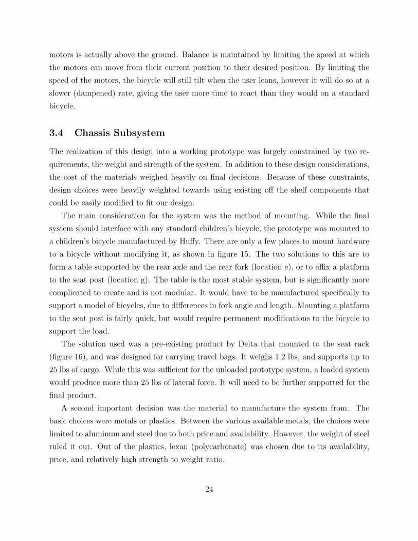
The main consideration for the system was the method of mounting. While the final
system should interface with any standard children’s bicycle, the prototype was mounted to
a children’s bicycle manufactured by Huffy. There are only a few places to mount hardware
to a bicycle without modifying it, as shown in figure 15. The two solutions to this are to
form a table supported by the rear axle and the rear fork (location e), or to affix a platform
to the seat post (location g). The table is the most stable system, but is significantly more
complicated to create and is not modular. It would have to be manufactured specifically to
support a model of bicycles, due to differences in fork angle and length. Mounting a platform
to the seat post is fairly quick, but would require permanent modifications to the bicycle to
support the load.
The solution used was a pre-existing product by Delta that mounted to the seat rack
(figure 16), and was designed for carrying travel bags. It weighs 1.2 lbs, and supports up to
25 lbs of cargo. While this was sufficient for the unloaded prototype system, a loaded system
would produce more than 25 lbs of lateral force. It will need to be further supported for the
final product.
A second important decision was the material to manufacture the system from. The
basic choices were metals or plastics. Between the various available metals, the choices were
limited to aluminum and steel due to both price and availability. However, the weight of steel
ruled it out. Out of the plastics, lexan (polycarbonate) was chosen due to its availability,
price, and relatively high strength to weight ratio.
24
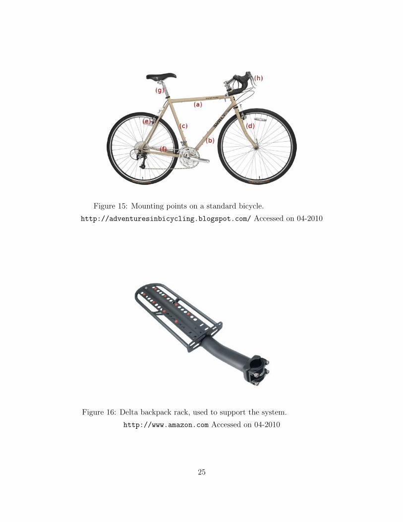
Figure 15: Mounting points on a standard bicycle.
http://adventuresinbicycling.blogspot.com/ Accessed on 04-2010
Figure 16: Delta backpack rack, used to support the system.
http://www.amazon.com Accessed on 04-2010
25
The initial prototype made use of a large amount of aluminum extrusion due to the
ease of mounting additional hardware to it. However, upon completion of the prototype, it
was found that the strength that it provided over lexan was not required, and a significant
amount of weight could be saved through the use of lexan over aluminum extrusion.
3.5 Actuation Subsystem
Actuation of the arms requires high torque, low rpm motors. In addition, as the arms need to
move independently, two motors are required. Excluding the battery, the motors contribute
the most weight to the system, and consume the majority of power in the system, so attention
must be paid to these requirements as well. For the unloaded prototype, the motors must be
able to output enough torque to be able to support the bicycle and the weight of the system.
The motors chosen were two 12V motors from AME, originally purposed for windshield
wipers. They spin at 96rpm with no load, and can provide 325 in-lbs of torque. They are
also relatively light, each weighing only 2.7 lbs. Because the arms do not need to move fast,
and torque is preferred over speed, the motors had to be reduced down before driving the
arms. The target output speed was in the range of single-digit rpms. For these particular
motors, a 7 to 8 times reduction was aimed for.
There were several options to drive the arms, chain and sprockets, timing belt and pul-
leys, or direct drive. Chain is much cheaper, and more readily available than timing belts.
However, timing belts provide much more accuracy. The prototype was demonstrated with
chain and sprockets, rather than a timing belt and pulleys. To compensate the lack of accu-
racy, two potentiometers were used in a PID control loop to determine the actual position
of the arms.
3.6 Computation Subsystem
3.6.1 Processing System
The computation and processing for the overall system is handled by a PIC32MX460F512L
microprocessor (hereafter referred to as the PIC32) made by Microchip Technology Inc. It
is a 32 bit processor designed for embedded computing that runs at 80 Mhz. Some of the
features and built-in peripherals of the PIC 32 include:
• 78 IO pins
26

• 512 KB Flash program memory
• 32 KB Data RAM
• 5 16-bit timers with the option of using 2 timers as a single 32 bit timer
• 4 programmable DMA Channels
• 2 Dedicated USB DMA Channels
• 16 10-bit ADC Channels
• 2 comparators
The PIC32 is coded in C and compiled using the MPLAB C32 compiler. Included with
the compiler is the PIC32mx library which includes a large selection of functions that control
the various features of the PIC32 including the Analog to Digital converter (ADC), UART,
interrupt control registers (ICR), pulse-width modulation (PWM) generator, etc. Whereas
many embedded computing systems, such as the Atmel ATMEGA series, do not provide such
a library and require the user to write their own functions to perform direct manipulation
of control registers, the PIC32mx library provides a highly functional layer of abstraction
that is easy to use, but still provides full control of the functionality of the PIC 32 processor.
One issue of concern with the PIC 32 processor that was discovered during the course of this
project is that the ADC exhibits electronic signal bleed across it’s channels, which, when
the chip is used as-is, makes accurately reading an analog signal impossible when two or
more voltages are being applied to ADC channels (even if the channels are not being read
concurrently). To solve this issue, alternating channels of the ADC were grounded, however
this effectively reduced the number of usable ADC channels to 8
The Development board used for the PIC32 is the 32 bit PIC32 based USB Bit Whacker
(hereafter referred to as the UBW32) developed by Brian Schmalz and sold through Spark-
fun.com. The UBW 32 is a small, yet highly convenient development board. Some features
of the UBW 32 include:
• Designed to interface with a standard 0.1” protoboard
• Includes a USB ’mini-B’ port
27

• Can be powered either by an external power source, or through the power and ground
pins on a USB cable.
• Breaks out all of the PIC32’s 78 IO pins
• Includes 2 user defined buttons and a program reset button
• Includes a power indicator LED and 4 user defined LEDs
• Comes with a bootloader that allows for simple commands to be executed from a PC
over USB. The bootloader also allows for direct programming of the chip via USB,
eliminating the need for an In-Circuit Serial Programmer.
Figure 17: UBW32 development board
http://www.schmalzhaus.com/UBW32 Accessed on 04-2010
3.6.2 Software Development
The software development for the system was accomplished using a bottom-up approach.
First, low level tasks were designed and programmed as individual modular functions, with
related functions being grouped together in separate .c files. These low-level functions are
designed to control the PIC32 processor’s peripherals. Some make use of the pic32mxx
library, where others such as ReadADC() (an example of one of the low level functions
written for the program), must directly interface with the PIC32’s control registers using
macros such as ADC1CHSbits.CH0SA.
int ReadADC(int ch)
AD1CHSbits.CH0SA = ch; //Select Analog Input
AD1CON1bits.SAMP = 1; //start sampling
28

while (!AD1CON1bits.DONE); //wait to complete conversion
int returnVal = ADC1BUF0; //get the result from the ADC buffer
ADC1BUF0=0x0000; //clear the buffer
return returnVal; //return result
This function sets the Channel Select bits in the ADC control register on the PIC32
processor, it sets the Sampling bit on the control register to 1, it then waits for the status bit
to change to 1 signaling that the analog to digital conversion is complete (this is handled by
the PIC32 hardware) and gets the result from the buffer. ReadADC is one of the functions
defined in ADC.c. ADC.c is responsible for handling all the initialization and operation
functions of PIC32 microprocessor’s analog to digital converter. Other files in the software
include main.c, PID.c, motors.c, and UART.c. The individual functions contained in
these files can be seen in Appendix C. PID.c is responsible for determining the necessary
motor power at a given time-step using measurements taken from the sensors in a PID control
feedback loop which is illustrated in figure 18. motors.c is responsible for generating the
PWM signals as well as handling the timer interrupts required to generate said signals.
UART.c is responsible for outputting data from the program over the PIC32 processor’s
Universal Asynchronous Receiver/Transmitter (UART) bus. main.c is responsible for the
higher level functionality in the software including calculating the desired motor position
and executing one of several strategies to keep the bicycle balanced. It is also provides the
main program loop and entry point, and initializes all other software modules.
3.7 Sensing Subsystem
Several methods to handle the sensing requirements were investigated. The solutions ranged
from using a single sensor, or single integrated sensor, to the use of several separate sensors
spread across the system to augment each other’s inputs. The two final choices are outlined
below.
3.7.1 Separate Sensors: MEMS Accelerometer and Solid-State Gyroscope
The first method investigated for effectively detecting the tilt angle of the bicycle in real-
time was the use of a sensor package known as an Inertial Measurement Unit, or IMU. An
IMU works on the principle of measuring the forces exerted by the inertia of an accelerating
29

Figure 18: Schematic diagram demonstrating the control loop.
object to detect motion in both linear and angular degrees of freedom. Various IMU models
range in quality from highly accurate (and expensive) spring-mass-damper and gimbaled
gyro navigation systems, to much less accurate (but cheap) solid state accelerometer and
gyro integrated circuit systems. Because cost is a concern both for the construction of a pro-
totype and for the design of a consumer product, it was necessary to identify an inexpensive
IMU while simultaneously exploring software techniques that could be used to increase the
performance of the IMU.
The IMU that was investigated for the project was a circuit board consisting of two
separate sensors, an IDG500 2-axis MEMS gyroscopic angular rate sensor, and an ADXL
335 3-axis accelerometer. This sensor package was not only inexpensive, but had the added
advantage of having an output voltage range that matched the operating range of the Analog
to Digital Converter module on the microprocessor chosen for the prototype. Though these
two sensors together can detect motion in 5 degrees of freedom, they are not of high enough
quality to detect motion accurately in each degree of freedom individually and are not suitable
for inertial based navigation. This is due to the fact that the accelerometer package is very
sensitive to vibration and the gyro package is prone to drift.
30

3.7.2 Single Sensor: Inclinometer
The second method investigated to detect the tilt angle of the bicycle was the use of a single
axis UITS-2B inclinometer manufactured by CFX technologies. The UITS-2B inclinometer
is a low cost solid state sensor used to measure angular position with respect to the direction
of gravity. The sensor outputs an analog DC voltage that is proportional to the sine of tilt
angle. This output signal has a range of 0.5-4.5 volts. Because the PIC32 processor has an
analog input range of 0-3.3 volts, the output signal of the inclinometer must be shifted down
and attenuated to match the PIC32’s operating range using an op-amp circuit. After the
voltage has been attenuated, it can then be sampled by the ADC of the PIC32 processor to
and can be used to determine the desired position of the actuated arms.
Though more accurate and reliable than the software-filtered IMU, the UITS-2B incli-
nometer is not without it’s weaknesses. In particular it has a fairly slow response rate of 300
ms, and as such the measured tilt angle from the sensor lags slightly behind the measured
tilt angle of the bicycle. This can be compensated for by mechanically dampening the tilting
motion of the bicycle such that the impact of the 300 ms response time is reduced by reduc-
ing the maximum change in tilt angle over a 300ms period. The another weakness of the
UITS-2B inclinometer is that it’s accuracy degrades for measurements near 90. This is due
to the fact that the voltage output of the sensor is proportional to the sine of the tilt angle
rather than the tilt angle itself. Since the sine function had a slope of 0 at 90, the output
voltage of the sensor varies much less over a given range centered at 90 when compared to an
equal range centered around 0or 180. Fortunately, this issue is easily resolved by rotating
the orientation of the sensor by 90.
3.8 Electrical Integration Subsystem
The various electrical components of the system all have varying power and IO voltage
requirements. As such, the electrical and computing portions of the system cannot be in-
tegrated without designing for electrical compliance between components. This design was
accomplished largely through the utilization of independent lab power supplies that were set
up using a common ground, and signal conditioning circuits to ensure that both analog and
digital signals being generated and used by the various sensors, computing hardware, and
actuators, are either amplified or attenuated to the appropriate levels for each component.
Figure 19 illustrates the operation of the system, beginning with the generation of analog
31

sensor signals, and followed by the data processing performed on those signals in order for
the processor to generate output signals to actuate the motors.
Figure 19: Flowchart of the electrical subsystems.
3.8.1 System Power Integration
The overall system utilizes 4 separate power supplies to provide power to the system. The
motor controllers make use of a 12 Volt power supply to power the MOSFET driver circuit
32

Component Power Requirement I/O Voltage Range
PIC32 Processor USB POWER (3.3-5V) 3.3V
Motors 12V, up to 36A -
Motor Controllers 6-30V, up to 10A 5V
Inclinometer 12V 5V
Potentiometers Up to 5V (input voltage)
Table 1: Power Requirements
and a 5 Volt power supply to power the CMOS logic circuit. The Inclinometer makes use
of a 12 Volt current-limited power supply. The PIC32 microprocessor draws its power from
the 3.3 Volt PWR pin on a standard USB ’mini-B’ peripheral cable. The two feedback po-
tentiometers are also powered off of this 3.3 Volt power supply via the UBW32 Development
board, which in addition to providing an interface between the USB power and the chip also,
conveniently routes the USB power to an output pin on the printed circuit board. All of
these are summarized in table 1.
3.8.2 System Input/Output Signal Integration
To ensure IO signal compliance, it is necessary to employ signal conditioning circuits to
interface between non compliant components. There are two interface points that must be
addressed they are:
• The interface between the PIC32 processor and both motor controllers
• The interface between the PIC32 processor and the Inclinometer
It was necessary to employ an attenuation circuit between the output pin of the incli-
nometer which outputs a 0-5 Volt analog signal, and an ADC input channel on the PIC32
processor, which is rated for a 0-3.3 Volt input signal. It is also desirable for the attenuation
circuit to have a linear relationship between the input and output signals so as not to distort
the sensor output. To accomplish the task of linearly attenuating the signal, a simple voltage
divider with a gain of 23
was used. The voltage divider was made using a 2KΩ and 1KΩ
resistor
33

It is also necessary to employ amplification circuits between the digital output pins of
the PIC32 processor, which operate at 0V (low) or 3.3V (high) and the digital input pins
of the motor controllers, which operate at 0V (low) or 5V (high). Unlike the attenuation
circuit described above, linearity is not a design concern as the circuit is amplifying a digital
signal. The amplification circuits were build using LM358 Dual Op-Amp integrated circuit
packages. Rather than calculate the resistor values necessary to set the exact gain necessary
to amplify a signal from 3 to 5 Volts, the gain was instead set at 11 using a 10KΩ and a
1KΩ in a non inverting configurations, and the Op-Amp IC was powered using the same 5V
power supply as the motor controllers. By powering the ICs at 5 Volts and setting the gain
much higher than necessary, the signal simply clips at 5 volts. Because the circuit is dealing
with a digital signal this clipping is not a design concern.
A diagram of the final circuit used is pictured below (figure 20). The pinouts for the
PIC32, inclinometer, H-Bridge, and Sub-Circuit 1 are summarized in tables 2 through 5.
Figure 20: Schematic of the electrical subsystem.
34

Pin Function
1 PWM Out
2 Digital Out
3 Digital Out
4 PWM Out
5 Digital Out
6 Digital Out
7 GND
8 Analog In
9 Analog In
10 Analog In
11 PWR
Table 2: PIC32 Pinout in reference to figure 20
Pin Function
1 PWR
2 GND
3 Analog Out
Table 3: Inclinometer Pinout in reference to figure 20
35
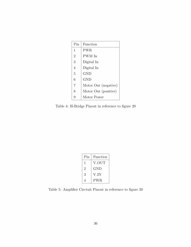
Pin Function
1 PWR
2 PWM In
3 Digital In
4 Digital In
5 GND
6 GND
7 Motor Out (negative)
8 Motor Out (positive)
9 Motor Power
Table 4: H-Bridge Pinout in reference to figure 20
Pin Function
1 V OUT
2 GND
3 V IN
4 PWR
Table 5: Amplifier Circtuit Pinout in reference to figure 20
36

4 Results
Results are presented here both as a qualitative analysis of the level of compliance for the
specifications designed for the prototype and as a presentation of numerical data gathered
from the system. The data was gathered over the PIC32’s serial interface and includes both
sensor input and motor control signal data. Figure 21 shows an overview of the prototype
system attached to the bicycle. The arms shown in these pictures were used for testing the
PID control loop. It was determined that using short arms presented less risk of damaging
the system in the event of a malfunction in the PID control loop. Figure 22 demonstrates how
the motors were mounted to the motor mounting plate, and how the chassis was supported,
and attached to the mounting platform (bicycle rack). Figure 23 shows a close up view of
the friction mounting system used to affix the system to the bicycle. Figure 24 shows a close
up view of the actuation subsystem, and how the arm drives the potentiometer via a timing
belt.
37

Figure 21: The completed prototype.
38

Figure 22: Rear of the system with testing arms attached.
39

Figure 23: The system mounted to the Delta bicycle rack.
40

Figure 24: The actuation subsystem with testing arms attached.
41

4.1 Data Collection and System Validation
Two experiments were performed to validate the system. The first experiment was designed
to determine how well the system was able to detect the tilt angle of the bicycle and calculate
the necessary arm position to maintain contact with the ground at a given tilt angle. This
was accomplished by disconnecting the chain between one of the support arms and the drive
motor such that the arm was able to rotate freely, and that the end of the arm would
maintain contact with the ground due to gravity. This allowed direct measurement of the
necessary arm position using the arm feedback potentiometer, because when the arm is
unchained, gravity keeps the arm in the proper position regardless of the tilt angle of the
bicycle. Data was collected for both the measured potentiometer readings (in bits) and the
calculated potentiometer values for the desired position of the arms based on data from the
inclinometer (in bits). The data was sampled at a rate of 388.2 samples per second for 10
seconds. Results can be seen in figure 25. It should be noted that the PIC32’s ADC exhibits
.24per bit of precision. Figure 26 shows the difference between the two values in bits. A
clear outlier can be seen, and there is a noticeable amount of noise in the data (which can
be attributed to the ADC), however it should be noted that 84% of the error data has a
magnitude of 10 bits or less, which corresponds to 2.4of difference between the position of
the arms measured by the potentiometer, and the position of the arms calculated using data
from the inclinometer. These results validate that our system can both accurately detect the
tilt angle of the bicycle, and correctly calculate the necessary position of the arm required
to maintain contact with the ground.
Figure 25: Calculated and measured arm position over time.
The second experiment was to investigate how well the PID control loop could actuate the
arm to a desired position over time. For this experiment, the arm was chained to the drive
42

Figure 26: Error between measured arm position and calculated required arm position over
time.
motor to complete the closed loop feedback between motor, potentiometer and inclinometer.
The bicycle was then manually tilted and data was collected for the measured potentiometer
readings (in bits), inclinometer output (in degrees), desired potentiometer values (in bits)
and motor output signal (in percent duty cycle). The data was sampled at a rate of 388.2 Hz
for 10 seconds. Because several different types of data were collected during this experiment,
the results are shown on several different graphs, however the scale of the horizontal axis
(time) is consistent between each graph. Figure 27 shows the actual and desired position of
the arm over time. Figure 28 shows the percent duty cycle of the pulse-width modulation
signal used to control the motors over time. Figure 29 shows the measured tilt angle of
the bicycle over time in degrees. Figure 30 shows the difference in bits between the actual
and desired position of the motors. Several inferences can be made from the data about
the efficacy in the pid loop controlling the motors. First, there is a small but consistent
time-delay between the desired and actual position of the motors that can be seen in figure
27. One cause for this time delay could be that as the error value decreases the duty cycle
of the motor control signal decreases, and at very low duty cycles (< 6%)the motors will
not move. This could be solved by increasing the integral gain constant in the PID control
loop, however this has the potential to increase the settling time or destabilize the control
loop. Another possible cause for the time-delay that has been described is that at the time
of the experiment, a noticeable amount of slack was observed in the chain. This slack could
decrease the mechanical response of the system to account for some or all of the observed
time delay. Another inference that can be made about the PID control system from the data
is that the system is quite accurate. It was found that 62.8% of the time, the actual position
of the arm was within 2.4(10 ADC bits) of the desired position. 88.5% of the time, the
43

position of the arm was within 3.6(15 ADC bits) of the desired position. 97% of the time
the motor was within 4.8(20 ADC bits) of the desired position. Though there is certainly
some room for improvement, these are very satisfying results.
Figure 27: Desired and actual arm positions over time.
Figure 28: PID-driven PWM motor control signal over time.
44
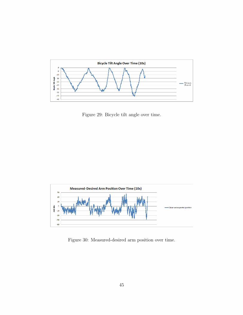
Figure 29: Bicycle tilt angle over time.
Figure 30: Measured-desired arm position over time.
45

4.2 Status of Prototype Specification and Requirement Compli-
ance
Currently all subsystem specifications set forth in Appendix A.1 have been met. In addition
the overall system specification set forth in Appendix A.1, The system must be able to
provide a corrective force when the bicycle is 45off from the vertical axis or less,
has been met. However at this time the bicycle is unable to bring itself to a vertical position
and thus the overall system requirements have not fully been met.
In addition to the requirements set forth for the prototype, several of the specifications
set forth in A.2 for the production quality version of the system have already been met. The
specifications that have been met are:
• The Chassis Subsystem shall allow for simple installation on a standard bicycle of a
given side using common household tools, it should be such that the System should be
easily installed regardless of the bicycle model or manufacturer. The only tool required
is one 316
” hex key.
• The Sensor(s) responsible for detecting the tilt angle of the Bicycle shall have a settling
time of no more than 384 milliseconds. (Met. Actual value is 300 milliseconds)
• The computing subsystem shall be able to sample all sensors, calculate necessary actu-
ator positions, and appropriately update all control signals at a rate of 384 milliseconds
or faster.(Met. Actual value is 300 milliseconds)
46

5 Discussion
The data collected in the results section clearly demonstrates that the software is successfully
controlling the actuated arms to an acceptable level of accuracy. This is demonstrated in
particular by figures 26 and 30, which show the difference between the calculated arm position
and the actual arm position, both in the chain and gravity driven cases, is consistently 5or
less. With this level of accuracy, it is reasonable to assume that the arms can be controlled in
such a way that a balanced system is achievable. A thorough investigation into the best way
to balance the system by actuating the arms still needs to be completed. It is recommended
that the strategies laid out in section 3.3 be part of this investigation.
Three major concerns that exist about the current design are the total system weight, the
electric power consumption and the total cost to build the system. The cost of the system
is broken down in Appendix B. With a total materials cost of $582, the projected price to
manufacture the system is a serious concern as the high price to manufacture a prototype
suggests that the ultimate cost to the consumer will be excessive. It will be necessary that
design changes take place to reduce the overall cost of the system. Total system weight is
currently a concern due to the fact that the system weighs 18 pounds, which is nearly equal
to the weight of the 22 pound bike. Nearly doubling the weight of the bicycle makes riding it
significantly more difficult. The third concern about the current system design is the power
consumption. It is anticipated that designing for an onboard power supply will significantly
increase the cost and weight of the system. A battery capable of powering the system for a
reasonable amount of time given the current design could potentially add significant weight
and cost to a system of which these totals are already a concern.
5.1 Marketability
If and when the design cycle for the system is completed, and assuming all the specifications
and requirements can be met in such a way that the cost to manufacture the system is
not prohibitive, it is believed that system will represent a very marketable product. With
respect to the system as a teaching tool for learning to ride a bike, the system is designed to
outperform training wheels, the current industry standard. The system exceeds the perfor-
mance in two different ways. First the polygon of stability formed by the actuated arms is
wider than that of training wheels, resulting in an overall more stable system. Second, the
level of balancing assistance that the system provides is adjustable when using either the tilt
47

angle correction at a threshold strategy or the tilt dampening strategy described in Section
3.3. By adjusting the level of assistance the system provides, the user can gradually wean
themselves off the system, whereas by comparison, there is little room for adjusting training
wheels, resulting in a much steeper learning curve when making the transition to a standard
two wheeled bicycle.
The System is also believed to be marketable as a physically therapeutic device for users
who may suffer from a developmental or cognitive disability and for users recovering from an
injury. This is due to the fact that bicycles are an excellent means of low-impact exercise,
and are excellent tools for training strength, endurance, balance and coordination, however
there are many conceivable circumstances where an injured or disabled person would not
be able to take advantage of the rehabilitative potential of a bicycle due to an inability to
maintain balance. When using the system, the user can adjust the level of balance assistance
that provides an appropriately challenging experience in a physical therapy program.
48

6 Conclusions
The Active-Assistance Balancing Mechanism that was designed over the course of this project
is an integrated system that makes use of mechanical and electrical hardware, and software
to accomplish the task of balancing a bicycle. Data collected during operation has validated
that the system has been properly modeled in software and can be controlled using closed
loop PID positional feedback control based on measured sensor data.
The system serves as a prototype for a marketable product that is envisioned to be easily
attached to any standard bicycle of a given size. It is believed that this product will be used
not only as a learning tool, but also as a means for a disabled or injured person to ride a
bicycle who might not otherwise be able to.
49

7 Future Work
There are several areas in which the system can be further developed in order to move the
project from a prototype to a marketable product. These design changes, which include
designing for modularity, safety and the inclusion of an on board power supply are intended
to increase the commercial viability of the system by satisfying requirements necessary for
the system to be sold as a finished product.
7.1 Designing for Onboard Power Storage
Currently, the system relies on laboratory DC power supplies and power from a USB cable to
power the various components of the system. Although this has been deemed an acceptable
solution to demonstrate the potential of the system, it is not considered an acceptable solu-
tion for a commercially viable product as it does not allow the user to use a bicycle equipped
with the self balancing system as one would use a normal bicycle (the bicycle cannot be
tethered to a stationary power supply). As such, the system must be redesigned to include
an on board power supply in the form of a battery in order to power the system. Changes
to the system should be made to meet the following specifications and requirements:
• Battery must be able to fit on the device, or otherwise be attached directly to the
bicycle
• Battery must be small enough not to interfere with normal mechanics of bicycle oper-
ation (actual value dependent on size of bicycle for which specific model is intended)
• Battery weight must not cause undue burden on user during normal operation of a
bicycle (actual value dependent on size of bicycle for which specific model is intended)
• Battery life must be at least 30 minutes under normal operating conditions between
charges
• Cost of battery must not be excessive (actual value unknown at this time)
To meet these specifications several design changes must be made to the system. The
biggest challenge to meeting these requirements is reducing the total power consumption of
the system in order to meet the battery life requirement without violating the size, weight
and cost requirements for the battery. Future design iterations will have to address the power
50

consumption of the motors, as they consume the majority of the system’s power budget. The
power consumption of the motors can be reduced by modifying the mechanical design of the
system such that less motor torque is required to maintain a balanced system, and thus less
power, or by identifying more efficient motors. It should be noted however that there will
likely be a cost tradeoff to using more efficient motors, which is undesirable in the design of
a consumer product.
Another design issue that must addressed will be the need to power multiple components
with different operating voltages from the same power source. Future iterations of the
project must incorporate power electronics to regulate voltage and current appropriately for
the motors, sensors, and microprocessor.
Finally a mounting system must be designed for the battery, the battery must be either
mounted to the chassis of the system, or mounted separately to the bicycle.
7.2 Designing for Modularity
Even if the system works effectively as an assistive balance mechanism for a bicycle rider,
it will be necessary for the system to be easy to use and install for a wide range of bicycles
if it is to become a viably marketable product. Although it is reasonable to assume that a
version of the system designed for a children’s bicycles will not be suitable for use with an
adult size bicycle, the product, the goal in designing for modularity is to make the system
easily adaptable to many different bicycle models of similar size. In order to do this, the
following specifications and requirements must be enforced for the system:
• Mounting system must be easy to use for the average consumer, requiring only common
household tools to attach the product to a bicycle
• Mounting system must be flexible, allowing for attachment to different bicycle models
of equivalent size
• System must require minimal assembly (note that this is different from the ease of
use requirement for the mounting system) the system should be nearly or entirely self
contained
– Necessary design changes
51

∗ All mounting points to the bicycle must be designed to be adjustable with
regards to their position and orientation relative to the rest of the system to
accommodate for varying bicycle designs
∗ All mounting points must be designed to be able to accommodate varying
pipe diameters for attachment
7.3 Designing for Safety
• Benefits
– Commercial viability is increased if the final product is safe for use by the con-
sumer, especially when the fact that the target includes children and people with
physical impairments
– Ethical considerations
• Specifications and requirements
– Normal operation of the system should pose negligible risk to the user (excluding
the inherent risks of normal operation of any bicycle)
– Probability of mechanical and electrical failures posing safety risks should be at
or below common commercial standards such as Six Sigma
• Necessary design changes
– All pinch points must be eliminated or shielded
– Power system must be compliant with the National Electrical Code (NEC) [10]
52

References
[1] K. Astrom, “Bicycle dynamics and control: Adapted bicycles for education and re-
search,” IEEE Control Systems Magazine, pp. 26–47, August 2005.
[2] D. Lin, “Static analysis of the stability of three-dimensional blocky systems around
excavations in rock,” International Journal of Rock Mechanics and Mining Sciences
and Geomechanics Abstracts, pp. 139–147, June 1988.
[3] G.-P. S. LLC, “System for providing gyroscopic stabilization to a two-wheeled vehicle,”
January 2008.
[4] L. Gyro-Precession Stability Systems, “System and method for providing gyroscopic
stabilization to a two-wheeled vehicle,” October 2009.
[5] Gyrobike, “Gyrobike - how it works,” April 2010. http://www.thegyrobike.com/
companyinfo-s/41.htm.
[6] C. H., “The stability of gyroscopic single track vehicles,” Engineer, November-December
1913.
[7] Y. Ou and Y. Xu, “Gyroscopically stabilized robot: Balance and tracking,” Interna-
tional Journal of Advanced Robotic Systems, vol. 1, no. 1, pp. 23–32.
[8] U. of California-Berkley, “Ghostrider motorcycle,” April 2010. http://journalism.
berkeley.edu/projects/mm/zack/thebike.html.
[9] M. M. C. Ltd., “Get to know murata boy!,” April 2010. http://www.murataboy.com/
en/about/index.html.
[10] N. F. P. Association, “National electrical code (NFPA 70),” 2008.
[11] R. J. Kosinski, “A literature review on reaction time,” Clemson University, 2008.
53

A Requirements
These are the specifications and requirements developed to benchmark and evaluate the
system. Strict requirements are evaluated on a ’met’ or ’not met’ basis. Loose requirements
may not be achieved due to design trade offs. Loose requirements may define a minimum
level of compliance.
A.1 Prototype
Overall System Requirements:
• The system must be able to bring the bicycle back to a vertical position when the
bicycle is 20off from the vertical axis or less. Loose Requirement
• The system must be able to provide a corrective force when the bicycle is 45off from
the vertical axis or less. The minimum acceptable level is 20. Loose Requirement
Chassis Subsystem Requirements:
• The chassis shall not be permanently attached to the bicycle. Strict Requirement
• The chassis shall remain securely attached to the bicycle at all times during operation
and will not require any action from the user to remain attached. Strict Requirement
• All components of the Sensing, Actuation, and Computing susbsystems shall be fixed
to the chassis subsystem, rather than the bicycle itself. Strict Requirement
Sensing Subsystem Requirements:
• The Sensing Subsystem shall consist of all electronic sensors and any necessary signal
conditioning circuits between sensors and the computing subsystem. Strict Require-
ment
• The Sensing Subsystem shall output an electrical signal proportional to the tilt angle
of the bicycle. Strict Requirement
• The sensing subsystem shall provide a motion or positional feedback signal from the
actuation subsystem. Strict Requirement
54

• The output voltage of all sensors shall at no time fall below or exceed the operating
voltage of the Analog to Digital Converter of the Computing Subsystem. Signal con-
ditioning circuitry may be used to shift or attenuate the output signal of a sensor in
order to meet this requirement. Strict Requirement
Actuation Subsystem Requirements:
• The Actuation Subsystem shall consist of all electromechanical actuators and their
controllers as well as any signal conditioning circuits between actuator’s controllers
and the computing subsystem. Strict Requirement
• The Actuation Subsystem shall generate the necessary corrective forces to maintain the
stability of the overall system. At minimum the system must provide a nonzero force to
dampen the system with respect to the tilt angle of the bicycle. Loose Requirement
• The actuator controllers shall take digital signals as inputs. The voltage range for
the digital signal shall be equal to that of the digital output pins of the computing
subsystem. Signal conditioning that meets this condition may be used to output a
different signal to an actuator controller. Strict Requirement
Computing Subsystem Requirements:
• The Computing Subsystem shall be capable of capturing data from all sensors. Strict
Requirement
• The Computing Subsystem shall be capable of determining the angular position of the
bicycle relative to the horizontal and the current position of all actuators based on
sensor data. Strict Requirement
• The Computing Subsystem shall be able to generate output signals to adequately
control the position of all actuators. Strict Requirement
• The Computing Subsystem shall be able to calculate the position of the actuators nec-
essary to execute a strategy to maintain the Bicycle’s stability. Strict Requirement
Power Subsystem Requirements:
• The power subsystem shall consist of a DC power source. Strict Requirement
55

A.2 Final Product
Overall System Requirements:
• The system shall meet all requirements and specifications set forth for the prototype
or a stricter requirement unless otherwise noted. Strict Requirement
• The system must be able to bring the bicycle back to a vertical position when the
bicycle is 20off from the vertical axis or less. Strict Requirement
• The system must be able to provide a corrective force when the bicycle is 45off from
the vertical axis or less. Strict Requirement
Chassis Subsystem Requirements:
• All components of the Sensing, Actuation, Computing, Power and User Interface sub-
systems shall be permanently fixed to the chassis subsystem. Strict Requirement
• The Chassis Subsystem shall be free of ’pinch points’ or shall provide significant protec-
tion such that any pinch points are not hazardous to the user. Strict Requirement
• The Chassis Subsystem shall provide significant protection to ensure that the user can
not be injured by any components used to transfer mechanical power such as gears,
chains, sprockets et cetera. Strict Requirement
• The Chassis Subsystem shall protect all electrical components of the system from
water damage during reasonably expected use cases (i.e. the system must be designed
to operate even in the case of rain, but prevention of damage caused by complete
submersion in water need not be designed for) Strict Requirement
• The Chassis Subsystem shall allow for simple installation on a standard bicycle of
a given size using common household tools. The System should be easily installed
regardless of the bicycle model or manufacturer. Strict Requirement
Sensing Subsystem Requirements:
• The Sensor(s) responsible for detecting the tilt angle of the Bicycle, φ, shall have a
settling time of no more than 384 milliseconds, based on measured average recognition
reaction times for humans [11]. Strict Requirement
56

Actuation Subsystem Requirements:
• The Actuators shall provide enough mechanical power to exert a torque on the system
(bicycle + rider) about the axis formed by the two contact points between the wheels
and the ground such that that torque is greater than the torque cause by gravity around
the same axis when the bicycle is at a tilt angle φ of 20. Strict Requirement
Computing Subsystem Requirements:
• the computing subsystem shall be able to sample all sensors, calculate necessary actu-
ator positions, and appropriately update all control signals at a rate of 384 miliseconds
[11] or faster. Strict Requirement
Power Subsystem Requirements:
• The Power Subsystem shall make use of a rechargable DC battery or battery bank.
The Amp-Hour capacity of the battery(s) shall be such that the system shall be able
to function properly for at least 2 hours Loose Requirement. Minimal acceptable
level is 30 minutes
• The Power Subsystem shall include power electronics to ensure that all electrical com-
ponents of the Overall System are supplied with the correct voltage as specified for
each component and are able to draw the necessary current required for their operation.
Strict Requirement
• The Power Subsystem shall incorporate overcurrent protection. Strict Requirement
User Interface Subsystem Requirements:
• The User Interface Subsystem shall include a battery life display. Strict Require-
ment
• The User Interface Subsystem shall include an audible low battery warning. Strict
Requirement
• The User interface Subsystem shall allow the user to adjust the degree to which the
Overall System actively provides balance assistance. Strict Requirement
57

B Budget
This is a manifest of all of the parts that were present on the prototype, and their respective
costs. These costs do not include shipping and handling.
Qty Part Model Manufacturer Price
Seat Rack Delta $30
1/8” Rubber Sheet $30
2 1/4” Shaft $16
#25 Roller Chain $25
4 Pulleys $10
2 50T Timing Belt $8
2 12V Gearmotor 226-series AME $140
1’x2’ Lexan $30
1”x1” Aluminum Extrusion 6061 1080 donation
Inclinometer UITS-2B CFX Technologies $250
PIC32/Development Board UBW32 Microchip / Sparkfun $40
2 Potentiometer $1.50
Total $582
58

C API
main.c:
• int main(void);
• void DelayMs(WORD ms);
• void Delay10us(DWORD dwCount);
• static void InitializeBoard(void);
• void setBalanceStrategy(int strategy);
• int calcArmPos(int incl);
ADC.c:
• int ReadADC(int ch);
• void ADCInit(void);
PID.c:
• void PID1init(int P, int I, int D);
• void PID2init(int P, int I, int D);
• calcPID1(int current, int desired);
• calcPID2(int current, int desired);
• void updateint1buffer(int error);
• void updateint2buffer(int error);
UART.c:
• void Write32UART1(unsigned int data);
• void Write32UART2(unsigned int data);
• void WriteUART32(unsigned int data);
59

• DWORD CalcBaud(DWORD Baud);
motors.c:
• void setMotorPower(int power);
• void ISR( CORE TIMER VECTOR, ip14);
• void CoreTimerHandler(void);
60

D PIC32 Datasheet
61

2008 Microchip Technology Inc. Preliminary DS61143E-page 1
PIC32MX3XX/4XX
High-Performance 32-bit RISC CPU:®
Microcontroller Features:
®
Peripheral Features:
2
®
Debug Features:
Scan
Analog Features:

PIC32MX3XX/4XX
DS61143E-page 2 Preliminary 2008 Microchip Technology Inc.
FIGURE 1: PIC32MX PACKAGE OUTLINE DRAWING
TABLE 2: PIC32MX GENERAL PURPOSE – FEATURES
TABLE 3: PIC32MX USB – FEATURES
General Purpose
Device Pins MHzProgram/ Data
Memory(KB)
Timers/Capture/Compare
EUART/SPI/I2C™
10-bit A/D (ch)
USB
Device Pins MHzProgram/Data Memory(KB)
Timers/Capture/Compare
EUART/SPI/ I2C™
10-bit A/D (ch)

PIC32MX3XX/4XX
DS61143E-page 6 Preliminary 2008 Microchip Technology Inc.
Pin Diagram (100-Pin USB)
20
2345678
10111213141516
656463626160
56
1718
2122
1
727170
686766
757473
5857
2423
25
5554535251
DD
SS
DD
DD
SS
SS
100-Pin TQFP (USB)
PIC32MX4XXL

2008 Microchip Technology Inc. Preliminary DS61143E-page 7
PIC32MX3XX/4XXTable of Contents
2

E UBW32 Schematic
66

Figure 31: UBW32 Schematic
67

F CAD Models
Figure 32: Isometric view of system.
68
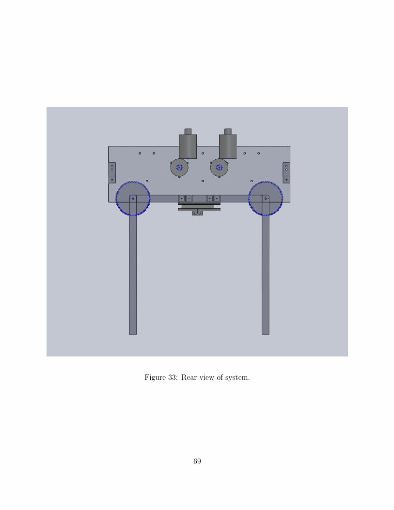
Figure 33: Rear view of system.
69
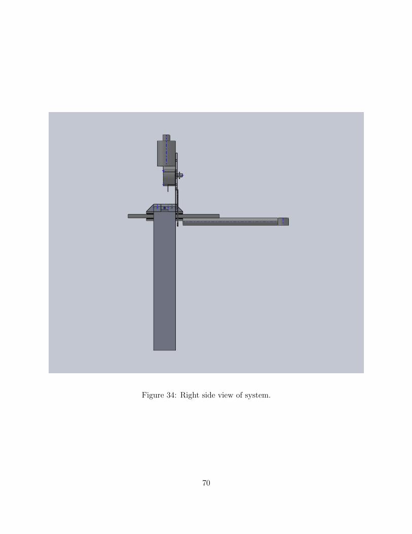
Figure 34: Right side view of system.
70

G PID Control Loop
/*
* PID.c
*
* Created on: Apr 27, 2010
* Author: sam
*/
float p1, p2, i1, i2, d1, d2; //gain values for PID control
//current and desired pot values
int current1, current2, desired1, desired2;
//storage of previous states for I and D components
float lastD1, lastD2, totalI1, totalI2;
float int1buf[255];
float int2buf[255];
int int1bufidx=0;
int int2bufidx=0;
void PID1init(int P, int I, int D)
p1 = (float)P;
i1 = (float)I;
czd1 = (float)D;
int i;
for(i = 0; i<255; i++)
int1buf[i]=0;
lastD1 = 0;
71

void PID2init(int P, int I, int D)
p2 = (float)P;
i2 = (float)I;
d2 = (float)D;
int i;
for(i = 0; i<255; i++)
int1buf[i]=0;
lastD2 = 0;
int calcPID1(int current, int desired)
int returnVal = 0;
float error = desired-current;
error = error/2;
updateint1buffer(error);
returnVal = p1*error + i1*(totalI2) + d1*(error - lastD1);
lastD1 = error;
//limit output to +-100
if (returnVal >100)
return 100;
if (returnVal <-100)
return -100;
72

//protection from driving past mechanical limit
//POTS MUST BE HOOKED UP CORRECTLY
if(current<655)
return 75;
if(current>1005)
return -75;
return returnVal;
int calcPID2(int current, int desired)
return 0;
updateint1buffer(int error)
if (int1bufidx == 0)
int1buf[int1bufidx] = int1buf[254]-int1buf[int1bufidx]+error;
int1bufidx++;
else if (int1bufidx == 254)
int1buf[int1bufidx] = int1buf[254]-int1buf[int1bufidx]+error;
int1bufidx=0;
else
int1buf[int1bufidx] = int1buf[254]-int1buf[int1bufidx]+error;
int1bufidx++;
73