Design of a Wide-Angle Infrared Thermography and Visible ... · Design of a Wide-Angle Infrared...
9
E. Gauthier, P. Chappuis, L. Doceul, D. Guilhem, J.B.Migozzi, Missirlian, H. Roche, E. Thomas, P. Andrew and JET EFDA contributors EFDA-JET-CP(05)02-15 Design of a Wide-Angle Infrared Thermography and Visible View Diagnostic for JET
Transcript of Design of a Wide-Angle Infrared Thermography and Visible ... · Design of a Wide-Angle Infrared...

E. Gauthier, P. Chappuis, L. Doceul, D. Guilhem, J.B.Migozzi, Missirlian,H. Roche, E. Thomas, P. Andrew and JET EFDA contributors
EFDA-JET-CP(05)02-15
Design of a Wide-Angle InfraredThermography and Visible View
Diagnostic for JET

.

Design of a Wide-Angle InfraredThermography and Visible View
Diagnostic for JET
E. Gauthier, P. Chappuis, L. Doceul, D. Guilhem, J.B.Migozzi1, Missirlian,H. Roche, E. Thomas, P. Andrew2 and JET EFDA contributors*
Association EURATOM-CEA, CEA/DSM/DRFC, CEA Cadarache, 13108 Saint Paul Lez Durance, France1JBM Optique, 11 av de la division Leclerc, 92310 SËvres, France
2EURATOM/UKAEA Fusion Association, Culham Science Centre, Abingdon, OX14 3DB, UK* See annex of J. Pamela et al, “Overview of JET Results ”,
(Proc.20 th IAEA Fusion Energy Conference, Vilamoura, Portugal (2004).
Preprint of Paper to be submitted for publication in Proceedings of theEPS Conference,
(Tarragona, Spain 27th June - 1st July 2005)

“This document is intended for publication in the open literature. It is made available on theunderstanding that it may not be further circulated and extracts or references may not be publishedprior to publication of the original when applicable, or without the consent of the Publications Officer,EFDA, Culham Science Centre, Abingdon, Oxon, OX14 3DB, UK.”
“Enquiries about Copyright and reproduction should be addressed to the Publications Officer, EFDA,Culham Science Centre, Abingdon, Oxon, OX14 3DB, UK.”

1
INTRODUCTION
The surface temperature of the plasma facing components needs to be measured to operate large,
additionally heated tokamaks in a safe manner and to calculate the power flux impinging on the
different parts of the machine [1]. In the framework of JET-EP (Enhanced Performances), a new
infrared thermography diagnostic is being developed. The objective is to provide a wide-angle
view in the infrared range (3 to 5µm) for thermography of the main chamber and divertor, aiming
at real time machine protection and analysis of the power flux deposition during normal operation
and transient events such as disruptions and ELMs.
OPTICAL DESIGN
In order to image a large section of the tokamak in both poloidal and toroidal directions, the optical
system has been designed with a field of view of 70 degrees, viewing the divertor, the inner wall,
the outer poloidal limiters, the ITER-like ICRH antenna and the top limiter (Fig.1). The diagnostic
is located in octant 8, in a lower limiter guide tube (horizontal port at 330mm below the equatorial
plan. An important aim of the optics design is that it should be ITER-relevant. To this end, the
optical components are mainly reflective, being the only kind which can sustain high neutron
radiation. The diagnostic consists of an endoscope formed by a tube holding the front head mirrors,
a Cassegrain telescope, and a relay group of lenses, the latter being connected to the camera body
[2]. The design uses a concave aspheric mirror located behind a flat mirror equipped with a small
aperture (Fig.2(a)). Both mirrors are made of stainless steel coated with gold. The combination of
the aspheric (primary) and flat (secondary) mirrors allows to bend the beam with an angle of 40o,
collimate the beam in the endoscope tube and place the black hole (shown in figure 1) in an acceptable
position in the image. The black hole in the field of view is due to the aperture located by purpose
in the flat mirror allowing to protect the primary mirror from plasma radiation and to minimize the
off-axis of the parabolic mirror in order to simplify the following optic. The Cassegrain telescope
(Fig.2(b)) is composed of elliptic and hyperbolic mirrors, both made of Zerodur glass (gold coated)
and a field group made of 2 Silicon lenses. Finally, the image is magnified and transmitted to the
detector with 4 Silicon and Germanium relay lenses (Fig.2(c)). The infrared camera is equipped
with a MCT detector, working in the 3.6-5.1µm range and cooled at 80K by using a closed loop
Stirling cooler. The Focal Plan Array (FPA) is formed by 640×512 pixels with a pitch size of 25µm
Additionally, a part of the photon flux is extracted in the Cassegrain telescope and transmitted
via a 200mm lens to a CCD camera, giving the same field of view in the visible range. Only a small
fraction of the light is used for the visible line: the part which would be lost due to the central
occultation, therefore the f number is the visible range is large (f# ~10) while the f number in the IR
range is about f# ~4.5.
Strong requirements apply to the shape and the positioning of the optical elements. The most
critical tolerances apply to the Cassegrain, which requires a mirrors surface quality of about 100nm
(0.3 fringe on interferometer test pattern) and a positioning precision of about 30µm. To fulfil these

2
constraints, a strong connection between optical and mechanical design is absolutely mandatory
and both merge in an opto-mechanical design. A 3D view of the diagnostic with the IR camera
installed on the endoscope is shown on figure 3.
PERFORMANCES
The main specifications in the design of the IR thermography diagnostic are the spatial resolution,
the dynamic range of the temperature measurement and the time resolution. The performance of
the system in term of spatial resolution is due on one hand, to the optics, and on another hand to the
number of pixels of the camera. In the present stage, commercial FPA detectors are limited to 640
lines by 512 columns. With a pitch size of 25µm, the limit in resolution for the camera is 20 cycles
per millimetre. The system is diffraction limited for all the points in the field and all incident light
is focused within the pixel size. The criterion retained for the space resolution of the optic is based
on the Modulation Transfer Function (MTF) measurement. The theoretical MTF curve obtained
with the optical code (Zeemax) is plotted on figure 4. The expected yield at 20 cycles per mm gives
a resolution of 8 mm at a distance of 3 meters, with a contrast of 40%. For absolute temperature
measurement with an error bar of 10% (MTF >80%), space resolution is reduced by a factor 2.
Thanks to the gold coating, the reflection on the mirrors is close to 98% ; taking into account the
transmission of the lenses, the global transmission of the endoscope is larger than 60%. A large
transmission factor is required, not only to get a high photon flux allowing to perform acquisition
with short integration time, but also to minimize the parasitic flux emitted by the hot optics with an
emissivity ε = 1-R , where R is the reflection or transmission coefficient for the mirrors or lenses,
respectively. In that respect, the main source of stray light will be produced by the uncoated double
sapphire window, located at the front of endoscope and at a temperature of 200oC.
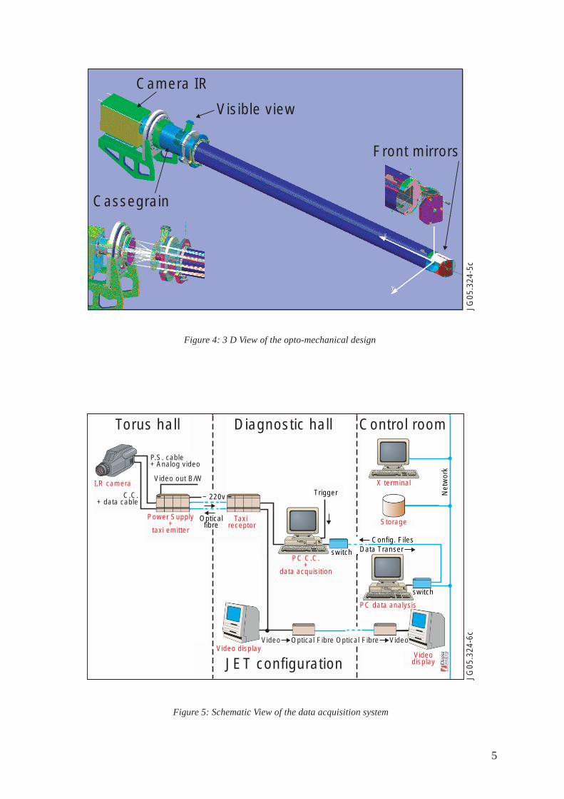
REMOTE CONTROL AND DATA ACQUISITION SYSTEM
The diagnostic should be able to measure from operating temperature of 200oC up to a maximum
temperature of 2000oC. Nevertheless, the photon flux follows a non linear dependence with the
surface temperature (ϕ = σT4 over the full spectral range), limiting the dynamic range of the
temperature measurements. In our case, the dynamic range is enhanced by using a multi integration
time : three integration time are used and the corresponding frames are combined in a single thermal
image. The acquisition of the raw data is performed in 14 bits and the reconstructed frame, with the
full dynamic range, is stored in 16 bits. The pixel clock is set at 10MHz and with four parallel
readout systems, we can achieve a frame rate of 100Hz with a full image size. The maximum frame
rate can be increased up to 10kHz by reducing the image size to 128×8 pixels, located at any
position in the field of view. With an image of 640×512 pixels and a frame rate of 100Hz, the data
flux is about 65MB/s. The storage capability has been limited to 1GB per shot (~15s of acquisition).
Data are first written locally on the diagnostic PC and then transmitted at the end of the pulse to
Codas for storage. Additionally to the numerical data, an analog video output is available in real

3
time in the JET control room. Both digital data and video signal are transmitted from the torus hall
to the diagnostic hall through optical fibres (Fig.6). Control of the camera (integration time, duration,
size and location of the image, etc) is performed from the control room by using an HTTP server
protocol.
CONCLUSION
In the framework of the JET-EP program, a new infrared thermography and visible view diagnostic
has been designed using mainly reflective optics. The wide-angle field of view will permit to observe
a large fraction of the Plasma Facing Components (divertor, ITER-like ICRH antenna, inner, outer
and top limiters). The endoscope and the infrared camera are in manufacturing phase and should be
delivered at JET in summer 2005.
REFERENCES :
[1]. A.E. Costley et al, Diagnostics for ITER, Varenna, Aug. 1995
[2]. J.B. Migozzi, E. Gauthier, internal note CEA, DIAG/NTT-2004.017, CEA Cadarache
Figure 1: Field of view in the infrared and visible range
Detector edge
Detector edge
The "Hole"
Edge of the head’s mirrortruncated by the tube wall
Tube’s wall truncation
Detector’s edge bent by distortion
JG05.324-1c
9
8
1
10¡
20¡
30¡
35¡40¡
2
67 5
4
3

4
Figure 2: Optical design of the front mirrors (a),Cassegrain (b) and relay group lenses (c)
Figure 3: MTF curves of 9 points in the FOV
(a)
JG05
.324
-2a
Axis of the spheric mirror
The hole in the mirroris to be minimized
115m
m
40o
(b)
JG05
.324
-2b
Sapphire window holding the secondary mirror
Mirror for visible way
Fieldgroup
sapphire vacuum window
Primary mirrorVisible rays
Telecentric interface imageplane (close to the lense face )
(c)
6.38mm is the decentrationCassegrain vs. Relay
Cassegrain axis
Anti-ghostship
Relay axis
JG05
.324
-2c
0.1
0.2
0.3
0.4
0.5
0.6
0.7
0.8
0.9
0
1.0
28.710 57.42
Mod
ulus
of t
h O
TF
Spatial frequency in cycles per mmPolychromatic diffraction modulation transfer function
JG05
.324
-4c
TS 0.00, -20.0 DEGTS 0.00, 0.0 DEGTS 0.00, 27.0 DEGTS 0.00, -27.0 DEG
TS 35.5, 0.0 DEGTS 25.0, 28.9 DEGTS 28.5, -26.5 DEG
5
Figure 5: Schematic View of the data acquisition system
Figure 4: 3 D View of the opto-mechanical design
Cassegrain
Camera IR
Visible view
Front mirrors
JG05
.324
-5c
Torus hall Diagnostic hall
JET configuration
Control room
JG05
.324
-6c
P.S. cable+ Analog video
C.C.+ data cable
Power Supply+
taxi emitter
PC C.C.+
data acquisition
X terminal
Storage
PC data analysis
Videodisplay
Video display
Config. FilesData Transer
switch
Taxi receptor
Opticalfibre
switch
Trigger Net
wor
k
~ 220v
I.R cameraVideo out B/W
Video VideoOptical FibreOptical Fibre