DESIGN OF A VERSATILE, - NASA
108
DESIGN OF A VERSATILE, TELEOPERABLE, TOWABLE LIFTING MACHINE WITH ROBOTIC CAPABILITIES FOR USE IN NASA'S LUNAR BASE OPERATIONS Submitted to: Mr. James A. Aliberti NATIONAL AERONAUTICS AND SPACE ADMINISTRATION Advanced Projects, Technology, and Commercialization Office Prepared by: Elizabeth Harris James Ogle, Team Leader Dean Schoppe Mechanical Engineering Department THE UNIVERSITY OF TEXAS AT AUSTIN Austin, Texas Fall 1989 (NASA-CR-I_6_) _ESIGN _F A VERSAT[L£, TFLFOPERAnL_t TnWAELE LIFTING MACHINE WITH R_OIIC CAPAuILIIIES FGR tJS_! IN NASA'S LUNAR _AS_ _PCRATTi_S (texas Univ.) LOS p CSCL I3I G3/37 _90-25_45
Transcript of DESIGN OF A VERSATILE, - NASA

DESIGN OF A VERSATILE,
TELEOPERABLE, TOWABLE LIFTING
MACHINE WITH ROBOTIC
CAPABILITIES FOR USE IN NASA'S
LUNAR BASE OPERATIONS
Submitted to:
Mr. James A. Aliberti
NATIONAL AERONAUTICS AND SPACE ADMINISTRATION
Advanced Projects, Technology, and Commercialization Office
Prepared by:
Elizabeth Harris
James Ogle, Team LeaderDean Schoppe
Mechanical Engineering DepartmentTHE UNIVERSITY OF TEXAS AT AUSTIN
Austin, TexasFall 1989
(NASA-CR-I_6_) _ESIGN _F A VERSAT[L£,
TFLFOPERAnL_t TnWAELE LIFTING MACHINE WITH
R_OIIC CAPAuILIIIES FGR tJS_! IN NASA'S LUNAR
_AS_ _PCRATTi_S (texas Univ.) LOS p
CSCL I3I G3/37
_90-25_45

MECHANICAL ENGINEERING DESIGN PROJECTS PROGRAM
_\i:, THE UNIVERSITY OF TEXAS AT AUSTIN
ETC 4.102" Austin, Texas 78712-1063" (512) 471-3900
November 15, 1989
James A. Aliberti, Manager of Research Programs
Mail Stop PT-PMO
Kennedy Space Center, F1 32899
Dear Mr. Aliberti:
Attached please find our final report entitled "Design of a Versatile,
Teleoperable, Towable Lifting Machine with Robotic Capabilities for
use in NASA'S Lunar Base Operations". The report contains a
discussion of alternate designs developed by the design team, the
final design solution, and our conclusions and recommendations. The
final design solution is a variable angle crane with a telescoping
boom, a cable and hook for heavy lifts, and a robot arm with a three
jaw gripper for light, dextrous lifts.
The design team appreciated the opportunity to work on this project
and looks forward to seeing you at our design presentation. The
presentation will take place on Tuesday, December 5, 1989, at
ll:00am in the Engineering Teaching Center II, ETC 4.110, on the
campus of The University of Texas at Austin. A catered luncheon
will follow the presentation.
Thank you for your support.
Sincerely,
Elizabeth Harris Dean Schoppe
_gl_,_Team Leader

ACKNOWLEDGEMENTS
The design team would like to thank the Universities Space
Research Administration and Mr. James A. Aliberti from the
Advanced Projects, Technology, and Commercialization Office of the
National Aeronautics and Space Administration for sponsoring this
project.
Special thanks goes to Dr. Robert Freeman from the Mechanical
Engineering Department at The University of Texas at Austin for
serving as faculty advisor to the design team and providing guidance.
Thanks also goes to Dr. Wallace Fowler, Mr. George Davis, and
Ms. Barbara Kozel from the Aerospace Department at The University
of Texas at Austin for providing much needed information and advice
throughout the project.
We would also like to thank Mr. Wendell Dean at The University
of Texas at Austin for his lectures and graphics help.
We thank Mr. Bert Herigstad at The University of Texas at
Austin for his suggestions, clerical help, and assistance with
preparing the written report.
Thanks also go to Mr. Rick Connell, our teaching assistant at
The University of Texas at Austin, for all of the help, suggestions,
and inspiration in planning and preparing the report.
And finally, special thahks also go to Dr. Stephen P. Nichols,
Professor of Mechanical Engineering at The University of Texas at
Austin, for overseeing the Senior Design Projects Program and for
his lectures throughout the semester.
ii

ABSTRACT
DESIGN OF A VERSATILE, TELEOPERABLE, TOWABLELIFTING MACHINE WITH ROBOTIC CAPABILITIES
FOR USE IN NASA'S LUNAR BASE OPERATIONS
The Universities Space Research Association (USRA) in
conjunction with NASA has requested the design team to design a
versatile lifting machine for lunar base surface operations. The
lifting machine will assist in lifting cargo off of landers sent to themoon and in the construction of a lunar base.
The design team considered three possible designs for theoverall configuration of the lifting machine: the variable angle
crane, the tower crane, and the gantry crane. The design team also
developed alternate designs for the major components of the liftingmachine.
The design team chose a teleoperable, variable angle crane as
its final design. The design consists of a telescoping boom mounted
to a chassis that is supported by two conical wheels for towing and
four outriggers for stability. Attached to the end of the boom is a
seven degree of freedom robot arm for light, dexterous, lifting
operations. A cable and hook suspends from the end of the boom for
heavy, gross, lifting operations.
The design team determined approximate structural sizes forthe lifter and its components. However, further analysis is needed
to determine the optimum design dimensions.
Lastly, the design team constructed a model of the design
which demonstrates its features and operating principals. This
model is capable of integration with the modets_ built by the otherNASA teams in The University of Texas at Austin Mechanical
Engineering Design Projects Program.
KEY WORDS:
ElizaT:}eth Harris
Dean Schoppe
CRANE, LIFTER, ROBOTIC, LUNAR, TELEOPERATED
"James Ogle, Team Leader
iii

TABLE OF CONTENTS
ACKNOWLEDGEMENTS ............................................................................. i i
ABSTRACT ..................................................................................................... iii
LIST OF FIGURES ....................................................................................... vii
1. INTRODUCTION ...................................................................................... 1
1.1 Background ................................................................................. 2
1.2 Project Requirements ........................................................... 31.3 Design Criteria ......................................................................... 3
1.4 Design Methodology ................................................................ 4
2. ALTERNATE DESIGNS OF THE LUNAR LIFTER AND
ITS COMPONENTS ................................................................................ 6
2.1 Overall Configuration for the Lunar Lifter .................. 7
2.1.1 Variable Angle Crane ................................................. 72.1.2 Tower Crane ................................................................... 9
2.1.3 Gantry Lifter ................................................................. 11
2.2 Components of the Lunar Lifter Design ......................... 13
2.2.1 Boom Component .......................................................... 14
2.2.1.1 Plain Truss Boom ........................................ 14
2.2.1.2 Folding Boom ................................................. 16
2.2.1.3 Telescoping Boom ....................................... 18
2.2.1.4 Tong Boom ...................................................... 18
2.2.2 Lifting Mechanism Component ............................... 20
2.2.2.1 Robot Arm End Effector ............................ 21
2.2.2.1.1 Parallel Gripper ......................... 22
iv

TABLE OF CONTENTS (cont.)
2.2.3
2.2.4
2.2.5
2.2.2.1.2 Three Jaw Gripper .................... 22
2.2.2.1.3 Bayonet Mount ............................. 25
2.2.2.2 Cable End Effector ...................................... 27
2.2.2.2.1 Hook ................................................. 27
2.2.2.2.2 Ball .................................................. 29
2.2.2.2.3 Electromagnet ............................ 29
Stabilizer Component ................................................ 30
2.2.3.1
2.2.3.2
2.2.3.3
2.2.3.4
2.2.3.5
Counter Balance Boom ............................... 31
Outriggers ...................................................... 31Anchors ............................................................ 33
Hook Lifter to Solid StationaryStructure ........................................................ 35
Trough of Regolith (Lunar Soil) ............ 36
Transport Media Component .................................... 36
2.2.4.1
2.2.4.2
2.2.4.3
2.2.4.4
2.2.4.5
Conventional Wheels .................................. 38
Conical Wheels ............................................. 38
Track ................................................................. 40
Tri-star Assembly ...................................... 42
Walking/Trailer Combination ................ 42
Energy Conversion and Storage Mechanism
Component ...................................................................... 44
2.2.5.1
2.2.5.2
2.2.5.3
2.2.5.4
Motor/generator .......................................... 45
Flywheel .......................................................... 46Dual Boom ....................................................... 46
Spring ............................................................... 47
V

TABLE OF CONTENTS (cont.)
2.3 Summary of Alternate Designs .......................................... 48
3. DESIGN SOLUTION ............................................................................. 50
3.1 Overall Configuration for the Lifter ................................. 50
3.2 Components of the Lifter ..................................................... 55
3.2.1 Telescoping Boom ........................................................ 55
3.2.2 Three Jaw Gripper ....................................................... 573.2.3 Hook .................................................................................. 59
3.2.4 Outriggers ....................................................................... 593.2.5 Conical Wheels .............................................................. 61
3.2.6 Motor/generator .......................................................... 61
3.3 Other Design Considerations ............................................... 64
3.3.1 Protection System ....................................................... 64
3.3.2 Teleoperation System ................................................ 663.3.3 Dismount from Lander .............................................. 66
3.4 Summary of Design Solution ................................................ 69
4. CONCLUSIONS AND RECOMMENDATIONS ........................... 70
BIBLIOGRAPHY .......................................................................................... 72
APPENDICES
A. Physical Characteristics of the Earth and Moon ......... A1B. Decision Matrices ..................................................................... B1
C. Boom Analysis .......................................................................... C1
D. Outrigger Analysis .................................................................. D1
E. Lifter Specifications ................................................................ E1
vi

Figure No,
LIST OF FIGURES
2.1
2.2
2.3
2.4
2.5
2.6
2.7
2.8
2.9
2.10
2.11
2.12
2.13
2.14
2.15
2.16
2.17
2.18
2.19
2.20
Variable Angle Crane ....................................................
Tower Crane ......................................................................
Gantry Lifter ....................................................................
Plain Truss Boom ............................................................
Folding Boom ....................................................................
Telescoping Boom ...........................................................
Tong Boom ..........................................................................
Parallel Gripper ..............................................................
3 Jaw Griiper and Receptacle ...................................
Bayonet Connector .........................................................
Hook ......................................................................................
Ball .......................................................................................
Counter Balance Boom ..................................................
Outriggers ..........................................................................
Anachor Stabilizer .........................................................
Hook Lifter to Object ....................................................
Trough of Regolith .........................................................
Conventional Wheels .....................................................
Conical Wheels ................................................................
Track ....................................................................................
8
10
12
15
17
19
19
23
24
26
28
28
32
32
34
34
37
39
39
41
vii

LIST OF FIGURES (cont.)
Figure No. Pa_a
2.21
2.22
3.1
3.2
3.3
3.4
35
36
37
38
39
310
311
Tri-Star Wheels .............................................................. 41
Walking/Trailer .............................................................. 44
Overall Design .................................................................. 51
Seven DOF Robot Arm .................................................... 53
Turntable ............................................................................ 54
Boom and Outrigger Telescoping Sections .......... 56
Three Jaw Gripper .......................................................... 58
Hook Detail ........................................................................ 60
Outrigger Footpad Detail ............................................. 62
Wheels and Suspension ................................................ 63
Protection System ......................................................... 65
Teleoperations Schematic .......................................... 67
Dismount from Lander .................................................. 68
viii

INTRODUCTION
The sponsors for this design project are the Universities Space
Research Association (USRA) and the United States National
Aeronautics and Space Administration (NASA). USRA is a private,
non-profit corporation organized in 1969 by the National Academy of
Sciences. Its membership includes 58 universities across the United
States. USRA assists universities and other research institutions in
developing space science and technology. Presently, USRA directs
several programs and institutes for NASA. In one of the programs,
called the Advanced Design Program, USRA provides money to
universities allowing senior engineering design classes to work on
design projects related to space engineering. Through this program,
The University of Texas at Austin Mechanical Engineering Design
Projects Program will design a versatile lifting machine for lunar
base operations.
This report contains the development of a versatile,
teleoperable, towable lifting machine with robotic capabilities for
use in NASA'S lunar base operations. The first chapter of this report
describes the alternate designs for the overall configuration of the
lunar lifter and its components. The next chapter describes the final
design chosen by the design team. The remaining chapters are the
conclusions and recommendations of the design team and the
appendices.

2
1,1 BACKGROUND
NASA studied the feasibility of a manned lunar base through
the early 1970's, but the study was curtailed in the mid-1970's.
Currently, NASA is conducting a study of a manned lunar base to
determine what equipment must be developed prior to the landing of
the first mission. In the present scenario, missions will occur every
six months and will alternate between cargo and manned missions.
The first cargo lander will be sent to the moon by the year 2001 and
the first manned mission will be sent approximately six months
afterward.
The primary commercial benefit for establishing a lunar base
is the extraction of oxygen from the lunar soil. The feasibility of
future space exploration is enhanced by the availability of lunar
oxygen (LUNOX) to provide life support and to oxidize the fuel needed
for propulsion. LUNOX can be put into low lunar orbit (LLO) with less
energy than oxygen obtained on Earth thus reducing costs of future
missions. One goal of the lunar base is that the moon can serve as
an oxygen supply station.
The establishment of a lunar base will require the development
of specialized equipment. There is a need for a versatile lifting
machine capable of performing a variety of lifting and robotic
operations. This lunar lifter design project was submitted with the
following requirements and criteria.

3
1.2 PROJECT REQUIREMENTS
The design team has been asked to perform the tasks listed
below:
1. Design a versatile lifting machine for lunar base
surface operations.
2. Construct a model which demonstrates features
and operating principles.
1.3 DESIGN CRITERIA
The criteria for the lifting machine are as follows:
1, Capable of heavy and light, dextrous lift operations.
2. Configured for towing on the lunar surface.
3. Capable of being operated by teleoperations
(remote control) from within a pressurized vehicle
or by a person in an extravehicular activity (EVA)suit.
4. Powered by a separate energy source.
5. Capable of employing energy storage devices to
minimize power consumption.
6. Be lightweight to minimize the cost of transporting tothe moon.
7. Be of compact design to consume minimal cargo
space.
8. Operated with minimal manpower.
9. Designed for operation in the lunar environment.

4
1,4 DESIGN METHODOLOGY
The design team conducted a survey of literature to locate
work already done on lunar lifting machines or similar devices on
the Earth or moon. The characteristics of the lunar environment
were determined to identify factors that influenced the design of
the lifting machine (see Appendix A). Throughout the design process,
the team consulted with the three other teams from The University
of Texas Mechanical Engineering Design Projects Program working on
NASA projects, engineering professors, their faculty advisor, Dr.
Robert Freeman, and others.
Due to the complex nature of the lunar lifter design, the design
team identified the major components required for the lunar lifter.
The design team generated and evaluated several alternate designs
for the overall configuration of the lunar lifting device as well as
for its individual components.
Using a decision matrix, the design team chose the best design
for the overall configuration of the lunar lifting device and for its
components. The final overall configuration for the lunar lifter was
developed by optimizing the individual components of the overall
design.
Computer Aided Design (CAD) was used to create drawings of
the chosen design as well as the alternates. Finally, the team
constructed a model that demonstrates the operations and features
of the chosen lifter design solution. The model is capable of
integration with the other NASA models built by the above

5
mentioned Mechanical Engineering teams to form a composite
demonstration model.

ALTERNATE DESIGNS OF THE
LUNAR LIFTER AND ITS COMPONENTS
The brainstorming sessions conducted by the design team
resulted in three alternate designs for the overall configuration of
the lunar lifter. A description of each design along with the
advantages and disadvantages of each is given in this section.
These designs are as follows:
1. Variable angle crane,
2. Tower crane, and
3. Gantry lifter.
Due to the complex nature of the possible lunar lifter designs,
the design team identified the major components required for each
lifter design. The components of the lunar lifter designs were
considered individually in order to simplify the design process. A
description of each component along with its alternate designs are
presented later in this section. The components involved in the
design of the previously mentioned alternates are as follows:
1 . Boom,
2. Lifting Mechanism,
3. Stabilizers,
4. Transport media, and
5. Energy conversion and storage mechanism.
6

7
The team also considered possible materials for the structural
components of the lifter. As stated in the project criteria, the
materials used in the lifter design must be lightweight, strong, and
compatible with the lunar environment. These materials must resist
or be protected from the damaging effects of ultraviolet radiation
and thermal expansion due to extreme temperature variations (-175
to 150 degrees Celsius). The three materials for further
consideration are as follows:
1. Kevlar and/or graphite epoxy or resin composite structures,
2. Aluminum alloys, and
3. Magnesium alloys.
2.1 OVERALL CONFIGURATIONS FOR THE LUNAR LIFTER
This section considers designs for the overall configuration of
the lunar lifter. The design team generated three alternate designs
based on the design criteria for the project. The three alternate
designs are the variable angle crane, the tower crane, and the gantry
lifter.
2.1.1 Variable Anale Crane
The first idea considered for the overall design of the lunar
lifter is the variable angle crane (see Figure 2.1). This design

8
BOOM PIVOT
STABILIZERS
LIFTING
MECHRNISM
TRANSPORT MEDIR_R_
Figure P. I: VARIABLE ANGLE CRANE

consists of a boom attached to a chassis.
varying its angle horizontally as well as vertically.
manipulator is attached to the end of the boom for
operations and possibly
heavy vertical lifting.
insure stability.
9
The boom is capable of
A robot
dextrous
This design will require a mechanism to
The advantages of the variable angle crane are as follows:
1. Versatile design; boom angle may vary in pitch and
yaw.2. Has a low boom pivot point which allows the robot arm
to perform ground level operations.
The disadvantages of the variable angle crane are as follows:
1. Requires a stabilizing mechanism.
2. Relatively complex design.
2.1.2 Tower Crane
The second idea considered for the overall design of the lunar
lifter is the tower crane (see Figure 2.2). This design consists of a
boom attached to a vertical column which is connected to a chassis.
Attached to one end of the boom is a robot manipulator for lifting
operations. The opposite end supports a positionable counter ballast
weight for stability. The boom is capable of angular movement in

10
BOOM
/
/BRLLRST
TRRNSPORT
WEIGHT
MEDIR S
TELESCOPINGCOLUMN
LIFTING /
MECHRNISM
F;gur• 2.2: TOWER CRRNE

11
the horizontal plane only. Gross vertical positioning is provided by
extension or contraction of the vertical column.
The advantages of the tower crane are as follows:
1. Relatively simple design.
2. Counter ballast mechanism reduces moment loading on
chassis.
The disadvantages of the tower crane are as follows:
1. Limited to flat surfaces or inclined surfaces of small
angles.
2. May require knowledge of weight to be lifted in order
to position the counter ballast weight.
2.1.3 Gantry Lifter
The third idea considered for the overall design of the lunar
lifter is the gantry lifter (see Figure 2.3). The gantry lifter has a
robot manipulator that suspends vertically in a rectangular truss
structure. The truss structure is supported by four legs. The
position of the manipulator within the rectangular truss is
controlled by movable support beams that cross to form right angles.
Wheels or other transport mechanisms allow gross movement of the
lifted cargo.

12
CROSS MEMBERS
/
//
\! /
TRRNSPORT IIEDIR
7
\
?
/
F;gure 2.3: GANTRY LIFTER

13
The advantages of the gantry lifter are as follows:
1. Simple design.
2. Few moving parts.
3. Self stabilizing; does not require ballast weights.
The disadvantages of the gantry lifter are as follows:
1. Lack of versatility; the lifter must be positioned over
the object. This may not always be possible.
2. Not a compact design; bulky for towing or transport to
the moon.
2.2 COMPONENTS OF THE LUNAR LIFTER DESIGN
This section describes the individual components required for
the design of the lunar lifter. These components are as follows:
boom, lifting mechanism, stabilizers, transport media, and energy
conversion and storage mechanism. The alternate designs of the
components are described in this section along with the advantages
and disadvantages of each.
The boom component is not utilized in the gantry lifter design.
Also, the fixed angle crane and the gantry crane are inherently self
stabilizing, therefore the stabilizers are designed for the variable
angle crane only.

14
2.2.1 Boom Comoonent
One of the components of the lunar lifter design is the boom.
The boom enables the varying and fixed angle designs to extend a
lifting mechanism over the object to be lifted. The boom and lifting
mechanism can then provide a lifting force to elevate the cargo.
Several ideas were generated for the boom design and from these,
four alternate designs were considered. These designs are as
follows:
1. Plain truss boom,
2. Folding boom,
3. Telescoping boom, and
4. Tong boom.
2.2.1,1 Plain Truss Boom, The plain truss boom consists of
many rigidly attached links that are assembled into a truss
structure (see Figure 2.4). The boom has a shape similar to a tall,
slender pyramid.
The advantages of the plain truss boom are as follows:
1. Simple, proven technology.
2. Requires no additional energy for extension or
retraction of the boom.
3. Easy to maintain.

15
F;gure 2.4: PLAIN TRUSS BOOM

16
The disadvantages of the plain truss boom are as follows:
1. Not versatile; unable to extend or retract.
2. Bulky; would take up a lot of cargo space.
3. Unstable during towing over rough terrain due to the
bouncing of the extended boom.
2.2.1.2 Foldina Boom. The folding boom consists of several
hinged sections that enable the boom to fold to a compact form or be
extended to various lengths (see Figure 2.5). The variability in
length makes the folding boom useful for various lifting and robotic
operations. The hinges could be arranged so that the boom could
unfold vertically or horizontally.
The advantages of the folding boom are as follows:
1. Relatively simple design.
2. Capable of becoming compact for transport to the
moon and for stability during towing on the lunar
s u rface.
3. Easy to maintain and repair because all parts are
external and accessible.
4. Versatile because of adjustability of length.
The disadvantages of the folding boom are as follows:
1. Not able to extend or contract continuously.
2. Requires energy to fold and unfold.

17
EXTENDED
FOLDED
HINGE
Flour• 2.5: FOLDING BOOM

18
3. Requires development of a system to operate and lock
the hinged sections.
2.2.1.3 Telescor)ing Boom. The telescoping boom would extend
similar to the way a radio antenna extends (see Figure 2.6). Some
possible cross-sectional shapes are cylindrical and rectangular.
The advantages of the telescoping boom are as follows:
1. Capable of becoming compact for transport to the
moon and for stability during towing on the lunar
surface.
2. Versatile; able to extend or contract.
The disadvantages of the telescoping boom are as follows:
1. Relatively complex design.
2. Difficult to repair and replace internal parts.
3. Requires energy to extend or retract.
4. Requires additional controls to operate the extension
and retraction of the boom.
5. Tolerance problems exist due to the large thermal
expansion effects on the moon.
2.2.1.4 Tong Boom. The tong boom has characteristics similar
to a pair of fireplace tongs (see Figure 2.7). The boom assembly
consists of two tongs that are parallel to each other and connected

SECTION AR
©
19
R
RLTERNRTE
SECTION RR
Figure 2, B: TELESCOPING BOOM
LINER R
R
RCTURTOR
RT JOINT
Figur• 2.?: TONG BOOM

20
by links at each identical joint. The boom would operate in a
relatively simple manner. As the linear actuator retracts, the boom
extends and as the linear actuator extends, the boom retracts.
Vertical positioning of the end of the boom is accomplished by using
both the joint actuator and the linear actuator.
The advantages of the tong boom are as follows:
1. Capable of becoming compact for transport to the
moon and for stability during towing on the lunar
su rface.
2. Versatile; able to extend or contract.
3. Relatively simple design.
4. Easy to maintain and operate because all parts are
external and accessible.
The disadvantages of the tong boom are as follows:
1. Requires energy for extension and contraction.
2. Requires movement of several parts when in
operation.
3. High loads in joints may exist.
2.2.2 Liftina Mechanism Component
The second component of the lunar lifter design considered is
the lifting mechanism component. The lifting mechanism connects
the cross member box of the gantry lifter or the boom of the other
designs to the object being lifted. The Gifting mechanism is located

21
at the end of the variable and fixed angle crane booms and at the
cross member box. The payload will be secured to the lifting
mechanism by a combination of an end effector and either a robot
arm or cable powered by a winch.
One possible lifting configuration is to use the cable and robot
arm in conjunction with each other. In this configuration the cable
would be used for heavy lift operations. For cable use a method for
stabilizing the payload during lifting would have to be developed.
The robot arm would be used for light dexterous lifting and as an aid
for the placement of the cable's end effector. Another possible
lifting configuration is to use the robot arm exclusively for heavy
and light lift operations.
2.2.2.1 Robot Arm End Effectors. The end effector on the robot
arm is used for light dextrous lifting and possibly as an aid for
positioning the cable end effector and the cargo tag lines. Several
ideas were generated for the end effector for the robot arm and from
these, three alternate designs were generated. These designs are as
follows:
1. Parallel gripper,
2. Three jaw gripper, and
3. Bayonet mount.

22
2.2.2. 1.1 Parallel Griooer, The parallel gripper operates by
grasping an object between two parallel plates (see Figure 2.8). The
parallel gripper would be connected to a robot arm that would be
attached to the boom.
The advantages of the parallel gripper are as follows:
1. Multifunctional; can grasp various shaped objects.
2. Simple design.
The disadvantages of the parallel gripper are as follows:
1. Objects slip out of grasp easily,
2. Cannot handle heavy loads.
2.2.2.1.2 Three Jaw Griooer. The three jaw gripper has three
individually rotatable jaws that would be inserted into or around a
receptacle on the object to be lifted (see Figure 2.9). The jaws
would then expand or contract into the slots on the receptacle to
make a secure connection. The jaws would also be capable of
grasping other objects without receptacles such as tubular shapes
or objects with a protrusion. The three jaw gripper would be
connected to a robot arm that would be attached to the boom.

23
F ROBOT RRM
PRRRLLELPLRTES
F;gur• 2.8: PRRRLLEL GRIPPER

24
ROBOT RRM 7
RBLE JRW
SLOT
RECEPTRCLE 7
E:",, E:l
F;gure 2.9: 3 ,JRU GRIPPER RND
RECEPTRCLE

The advantages of the the three jaw gripper are as follows:
1. Provides a secure connection with no slipping,
turning, or pivoting.
2. Capable of grasping various shaped lightweight
objects without a receptacle.
3. Capable of heavy vertical lifting operations.
4. Capable of lifting and positioning lighter objects in
any orientation (objects that have a mating
receptacle).
The disadvantages of the three jaw are as follows:
1. More complex design.
2. Requires special fittings for secure connections.
3. Tolerances difficult to maintain due to thermal
expansion effects.
25
2.2.2.!.3 Bayonet mount. This gripper would connect to the
payload similar to the way an automobile brake light is put into
position (see Figure 2.10). The gripper would be inserted into a
receptacle, pushed forward against a spring force, turned, and
released so that it is locked into position. The Bayonet mount would
be connected to a robot arm that would be attached to the boom.
The advantages of the bayonet mount are as follows:
1. Provides a solid connection with no slipping, turning,
or pivoting.

26
ROBOT ARM
OUND
PIN
SPRING
SLO
MALE CONNECTOR FEMALE RECEPTRCLE
Figur• e. lO: BAYONET CONNECTOR

2. Capable of vertical heavy lift operations.
3. Capable of lifting and positioning lighter objects in
any orientation.
4. Simple design with no moving parts.
27
The disadvantages of the bayonet mount are as follows:
1. Not versatile; cannot lift objects without a mating
receptacle.
2. Maintenance of tolerances could be a problem.
2.2.2.2 Cable End Effectors. The end effectors on the end of the
cable are used for heavy vertical lifting. Several ideas were
generated for the end effector for the cable and from these, three
alternate designs were generated. These designs are as follows:
1. Hook,
2. Ball, and
3. Electromagnet.
2.2.2.2. 1. Hook. A hook would be attached to the end of the
cable and would fit into a receptacle attached to an object being
lifted (see Figure 2.11).
The advantages of the hook are as follows:
1. Simple; proven technology.

CflBLE
CRRGO
SURFRCETRCLE
28
Figure 2. 11" HOOK
CRRGO SURFRCESPHERE
TRIRNGULRR
SLOT
Figure 2. 12: BRLL

29
2. Reliable; no moving parts.
The disadvantages of the hook are as follows:
1. Difficult to connect to receptacle because it requires
guidance to hook onto objects.
2. Only hooks into rings or loops.
2.2.2.2.2. Ball. A ball would be attached to the end of the cable
and would fit into a triangular receptacle attached or built into an
object being lifted (see Figure 2.12).
The advantages of the ball are as follows:
1. Simple; proven technology.
2. Reliable; no moving parts.
3. Easily connected to receptacle.
The disadvantages of the ball are as follows:
1. Possibility of ball getting lodged in receptacle.
2. Requires a complex receptacle.
3. Unreliable, ball could come out of socket if payload
hangs up.
2.2.2.2.3 Electromaenet. An electromagnet would be
attached to the cable and would electromagnetically connect to a
smooth surface receptacle on the object being lifted.

The advantages of the electromagnet are as follows:
1. Easy to connect.
2. Utilizes an nonprotruding receptacle.
3. Simple design; no moving parts.
The disadvantages of the electromagnet are as follows:
1. Requires a large amount of energy to operate.
2. Must be made of a magnetic material (most are
heavy).
3. Unsafe; loss of energy results in the payload being
dropped.
3O
2.2.3 Stabilizer Comc}onent
The third component of the lunar lifter design considered is
the stabilizers. Stabilizers will keep the lifter from becoming
unbalanced and tipping over when lifting a load. Several ideas were
generated for the stabilizers and from these, five alternate designs
were considered. These designs are as follows:
1. Counter balance boom,
2. Outriggers,
3. Anchors,
4. Hooking lifter to solid stationary structure, and
5. Trough of regolith.
31
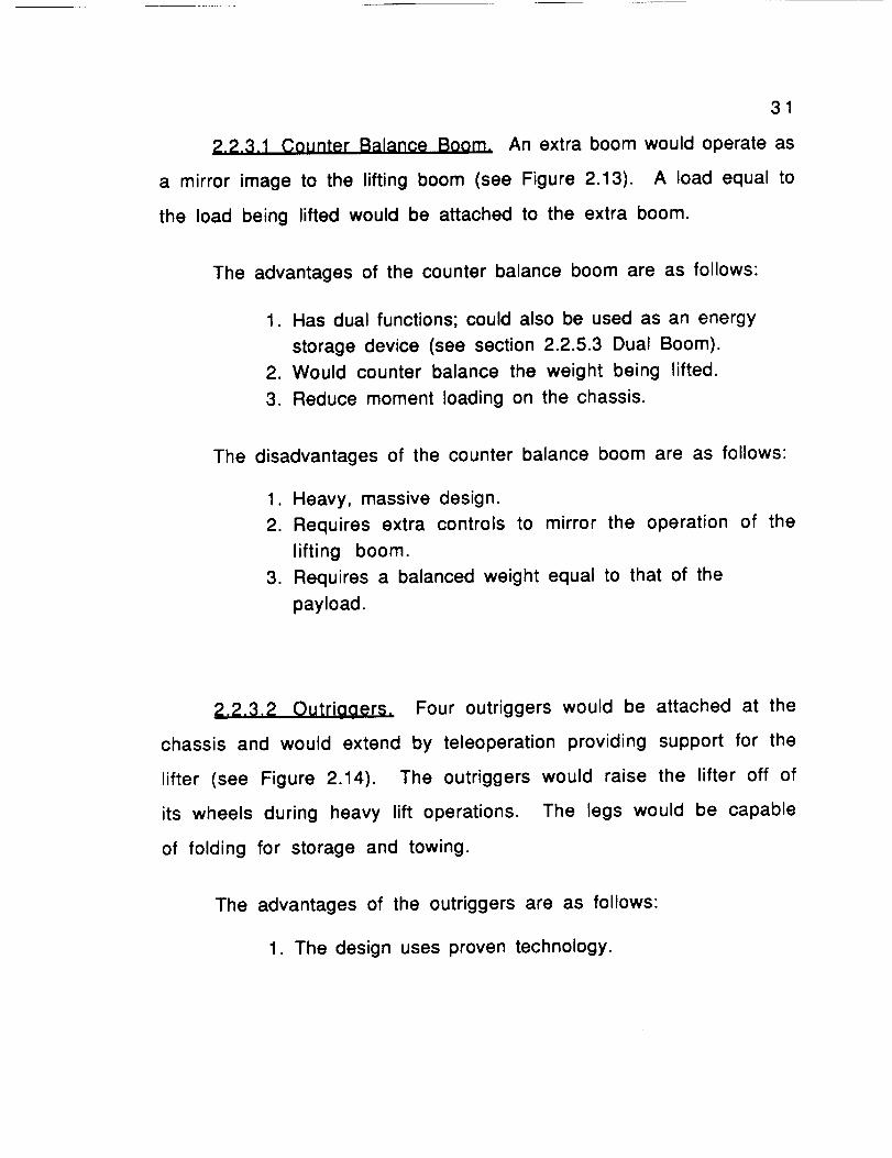
2.2.3.1 Counter Balance Boom. An extra boom would operate as
a mirror image to the lifting boom (see Figure 2.13). A load equal to
the load being lifted would be attached to the extra boom.
The advantages of the counter balance boom are as follows:
1. Has dual functions; could also be used as an energy
storage device (see section 2.2.5.3 Dual Boom).
2. Would counter balance the weight being lifted.
3. Reduce moment loading on the chassis.
The disadvantages of the counter balance boom are as follows:
1. Heavy, massive design.
2. Requires extra controls to mirror the operation of the
lifting boom.
3. Requires a balanced weight equal to that of the
payload.
2,2.3.20utrigaers. Four outriggers would be attached at the
chassis and would extend by teleoperation providing support for the
lifter (see Figure 2.14). The outriggers would raise the lifter off of
its wheels during heavy lift operations. The legs would be capable
of folding for storage and towing.
The advantages of the outriggers are as follows:
1. The design uses proven technology.

32
Figure 2.13: COUNTER BALANCE BOOM
RCTURTED
Figure 2. 14: OUTRIGGERS

33
2. Versatile design; capable of being used on rough
terrain.
3. Does not require a weight to balance load being lifted.
4. Wheels do not have to carry the load of the heavy lift
operations.
The disadvantages of the outriggers are as follows:
1. Requires actuators for each foot thus increasing the
weight of the design.
2. Requires energy to set up the outriggers.
2.2.3.3 Anchors, Four anchors would be inserted into the
ground and attached to each side of the chassis by a cable (see
Figure 2.15). The anchors would be in the shape of an arrow head
spike. A procedure for inserting the anchors securely in the ground
would have to be determined.
The advantages of the anchor are as follows:
1. Relatively simple design.
2. Requires minimal space and weight.
3. Good for a permanent lifting site.
4. Does not require a weight to balance the load being
lifted.
The disadvantages of the anchor are as follows:
1. Requires energy to insert anchors into ground.
2. Unreliable; not sure if anchor will hold in the ground.

34
ANCHOR
Figur• 2.15: ANCHOR STABILIZER
RIGID
RTTRCHMENT
\
Figur• e. 18: HOOK LIFTER TO OBJECT

3. Wasteful; the anchor could not be removed from
the ground and reused.
35
2.2.3,4 Hook Lifter to Solid Stationary Structure. The design
involves attaching the lifter's chassis to a solid stationary
structure such as the lander (see Figure 2.16). The lifter would
attach to the structure by a rigid attachment mechanism.
The advantages of hooking the lifter to a solid stationary
structure are as follows:
1. Utilizes existing structures on the moon, such as the
lander, therefore reducing the amount of extra
equipment taken to the moon.
2. Does not require a weight to balance load being lifted.
The disadvantages of hooking the lifter to a solid stationary
structure are as follows:
1. Not versatile; a solid stationary structure must be
present to stabilize the lifter.
2. Requires energy to set up the connections between the
lifter and the structure.

36
2.2.3.5 Trouah of Reaolith (Lunar Soil_. A trough surrounds the
chassis and is filled with regolith (see Figure 2.17). A procedure for
filling and emptying the trough of regolith would be developed.
Possible procedures might be a human in an EVA suit or a
teleoperated shovel operation.
The advantages of the trough of regolith are as follows:
1. Relatively simple design.
2. Lightweight when empty.
3. Utilizes materials on the moon (regolith).
The disadvantages of the trough of regolith are as follows:
1. Requires knowledge of weight needed to balance
the load being lifted.
2. Requires energy to insert the regolith.
2.2,4 Transport Media Comoonent
The fourth component of the lunar lifter design considered is
the transport media. The lifter will need a transport media to allow
towing on the lunar surface. Several ideas were generated for the
transport media and from these, five alternate designs were
considered. These designs are as follows:
1. Conventional wheels,
2. Conical wheels,

37
F;gure 2.17: TROUGH OF REGOLITH

3. Track,
4. Walking/trailer combination, and
5. Tri-star assembly.
38
2.2.4.1 Conventional Wheel_, Four wheels, similar in design to
automobile wheels on Earth, would be attached to the chassis for
towing behind a separate vehicle (see Figure 2.18). The wheels could
be inflatable or made from wire mesh. On the Apollo mission, the
wheels of the lunar rover were made of wire mesh.
The advantages of the conventional wheels are as follows:
1. Simple design; uses proven technology on Earth.
2. Suitable for use on the lunar surface.
The disadvantages of the conventional wheels are as follows:
1. The inflatable wheels are subject to punctures and
adverse effects of thermal expansion.
2. Difficult to repair.
2.2.4.2 Conical Whe_l_. The conical wheels have a gradual
tapering towards the axle (see Figure 2.19). The wheels could be
inflatable or made of wire mesh.

AXLE
=l ii
| i
i
i, i
i
L
39TRERD
F;guee 2. 18: CONVENTIOHRL WHEELS
F;gure 2. 19: CONICRL WHEELS
4O
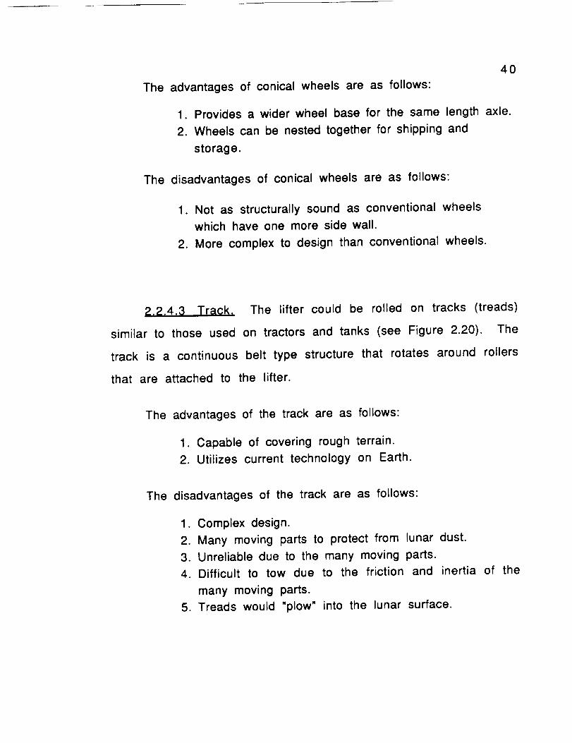
The advantages of conical wheels are as follows:
1. Provides a wider wheel base for the same length axle.
2. Wheels can be nested together for shipping and
storage.
The disadvantages of conical wheels are as follows:
1. Not as structurally sound as conventional wheels
which have one more side wall.
2. More complex to design than conventional wheels.
2.2.4.3 Track, The lifter could be rolled on tracks (treads)
similar to those used on tractors and tanks (see Figure 2.20). The
track is a continuous belt type structure that rotates around rollers
that are attached to the lifter.
The advantages of the track are as follows:
1. Capable of covering rough terrain.
2. Utilizes current technology on Earth.
The disadvantages of the track are as follows:
1. Complex design.
2. Many moving parts to protect from lunar dust.
3. Unreliable due to the many moving parts.
4. Difficult to tow due to the friction and inertia of the
many moving parts.
5. Treads would "plow" into the lunar surface.

41
F ;gure 2.20: TRACK
WHEELS
L LUNRR SURFRCE
Figure 2.21: TRI-STRR WHEELS

42
2.2.4.4 Tri-star Assembly. A Tri-star assembly is composed of
three wheels (see Figure 2.21) Two wheels are always in contact
with the ground and the third wheel is idle. If one of the wheels hits
an obstruction the assembly rotates over the obstruction. The idle
wheel comes in contact with the ground and the back wheel rotates
out of contact with the ground and becomes the idle wheel.
The advantages of a tri-star assembly are as follows:
1. Capable of covering rough terrain.
2. Lifter is still towable if one of the three tires on each
assembly fails since only two tires are needed.
The disadvantages of a tri-star assembly are as follows:
1. Complex design.
2. Assembly becomes large as wheel diameter increases.
3. Rotation of assembly upon hitting an obstruction could
cause lifter and/or payload damage due to shock
loading.
2.2.4.5 Walkin0/Trailer Combination. The lifter is supported
by teleoperable support legs extending from each corner of the
chassis (see Figure 2.22). This gives the lifter the ability to make
minor position adjustments by walking on the legs. Long distance
transportation would be provided by a separate trailer.

43
BOOM
\
TELEOPERRTED
LEGS
REMOVRBLE TRRILER
Figure 2.22: URLKING/TRRILER

44
The advantages of the walking/trailer combination are asfollows:
1. Capable of operating on rough terrain.
2. Can adjust its position easily.
3. Could be self stabilizing if leg span is wide enough.
4. Trailer could be designed and utilized for various uses
at the lunar base.
The disadvantages of the walking/trailer combination are asfollows:
1. Complex design; requires a separate system to control
movement of support legs.
2. More material since trailer is not an integral part
of lifter.
3. Higher energy consumption than static designs due to
the movement of the support legs.
2.2.5 Energy Conversion and Storage Mechanism
Component
The last component of the lifter considered was the energy
conversion and storage mechanism. An energy conversion and
storage mechanism would enable the lifter to utilize the potential
energy of the elevated cargo upon lowering it from the lander.
Several ideas were generated for the energy conversion and storage
mechanism and from these, four alternate designs were considered.

These designs are as follows:
45
1. Motor/generator,2. Flywheel,3. Dual boom, and
4. Spring.
2.2.5.1 Motor/aenerator. The motor/generator is a single
device that has two separate functions. The motor is used for
lifting operations and the generator is used for conversion of the
potential energy to electrical energy.
The advantages of the motor/generator are as follows:
1. Dual purpose device.
2. Readily available.
3. Reduces lifter weight due to the integration of two
functions if a motor is to be used as the driving
mechanism.
The disadvantages of the motor/generator are as follows:
1. A motor/generator cannot be used if a motor is not
being used as the driving mechanism.
2. Efficiency may be low for short, infrequent lifts.

46
2.2.5.2 Flywheel. A flywheel is a large disk that stores the
potential energy of the raised cargo. The potential energy of the
cargo is stored as rotational kinetic energy in the flywheel. The
energy can be transferred to and from the flywheel via a clutch
mechanism.
The advantages of the flywheel are as follows:
1. Common; readily available.
2. Simple; standard technology.
The disadvantages of the flywheel are as follows:
1. Must have large mass to store significant amounts of
energy if low angular velocities are desired.
2. Dangerous if a lightweight high angular velocity
flywheel is used.
3. Takes up large volume of space.
2.2.5.3 Dual Boom. The resulting energy gained from lowering
the cargo off of the lander could be stored as potential energy in the
dual boom's box of regolith (see Figure 2.13). As the cargo is
lowered, the box of regolith is lifted and as the cargo is lifted, the
box of regolith is lowered The cargo is attached to the box of
regolith via a cable network.

47
The advantages of the dual boom are as follows:
1. Utilizes existing moon resources (regolith).
2. Has dual functions; also used as stabilizer (see 2.2.3.1
Counter Balance Boom).
The disadvantages of the dual boom are as follows:
1. Requires energy to fill the box with regolith.
2. Requires additional control procedures to coordinate
the motion of the two booms and the box of regolith.
2.2.5.4 Spring. Springs would be attached at several locations
on the lifter. The springs store the cargo's potential energy when
the cargo is being lowered. This energy, stored in a compressional,
pneumatic, or torsional spring, may be used to aid the lifting of the
cargo.
The advantages of the spring are as follows:
1. Simple; standard technology.
2. Readily available.
The disadvantages of the spring are as follows:
1. Requires additional space to implement spring into
design.

48
2. Design may require several different spring sizes and
shapes.
3. Dangerous; failure could be harmful and catastrophic.
2.3 SUMMARY OF ALTERNATE DESIGNS
In summary, the design team's brainstorming sessions resulted
in three alternate designs of the lunar lifter. These designs are the
variable angle boom, the fixed angle boom, and the gantry lifter.
Upon further consideration, the team decided to examine the
individual components of the lifter separately. These components
are the boom, lifting mechanism, stabilizers, transport media, and
the energy conversion and storage mechanism. Several alternate
designs for each component were generated and evaluated. Moreover,
the team considered possible materials for the construction of the
lifter.
For the next step in the design process, the team utilized
decision matrix techniques to select the most desirable alternate
from the lifter design and each of the component designs. The team
then integrated these components into the chosen lifter design.

SUMMARY PAGE
49
ALTERNATE DESIGNS OF THE
LUNAR LIFTER AND ITS COMPONENTS
2.1 OVERALL CONFIGURATIONS FOR THE LUNAR LIFTER
2.1.1 Variable Angle Crane2.1.2 Tower Crane
2.1.3 Gantry Lifter
2.2 COMPONENTS OFTHE LUNAR LIFTER DESIGNS
2.2.1 Boom Component2.2.1.1 Plain Truss Boom2.2.1.2 Folding Boom2.2.1.3 Telescoping Boom2.2.1.4 Tong Boom
2.2.2 Lifting2.2.2.1
2.2.2.2
Mechanism ComponentRobot Arm End Effector
2.2.2.1.1 Parallel Gripper2.2.2.1.2 Three Jaw Gripper2.2.2.1.3 Bayonet MountCable End Effector2.2.2.2.1 Hook2.2,2.2.2 Ball2.2,2.2.3 Electromagnet
2.2.3 Stabilizer Component2.2.3.1 Counter Balance Boom2.2.3.2 Outriggers2.2.3.3 Anchors2.2.3.4 Hooking Lifter to Solid Stationary Structure2,2.3.5 Trough of Regolith (Lunar Soil)
2.2.4 Transport Media Component2.2.4.1 Conventional Wheels2.2.4.2 Coned Shaped Wheels2.2.4.3 Track2.2.4.4 Walking/Trailer Combination2.2.4.5 Tri-star Assembly
2.2.5 Energy2.2.5.12.2.5.22.2.5.32.2.5.4
Conversion and Storage Mechanism ComponentMotor/generatorFlywheelDual BoomSpring

DESIGN SOLUTION
This section presents the selection and design of the lunar
lifter and its components. The best designs were selected from the
alternate designs using a decision matrix process (see Appendix B).
The criteria for the decision matrix include the following factors:
safety, reliability, versatility, weight, energy usage, simplicity of
operation, compactibility, simplicity of design, and durability. The
following description of the final design is the result of two months
of research and design.
:_,1 OVERALL CONFIGURATION OF THE LIFTER
The design team chose the variable angle crane as the final
design solution for the overall configuration (see Figure 3.1). A
primary factor influencing the selection of the variable angle crane
was its versatility. The boom of the variable angle crane has
adjustable yaw (horizontal) and pitch (vertical); thus it has a large
work space.
For heavy lifting, a cable and winch system is used. The
winch, located on the chassis, controls a cable that extends through
the center of the boom out through the end where it hangs freely. At
the end of the cable is a hook that will be attached to the cargo to be
lifted. To prevent the lifted cargo from becoming unstable (e.g.
5O

/
/0
Q.
00U.
51
52
turning or swaying), tag lines extending from the chassis will be
connected to the cargo prior to lifting.
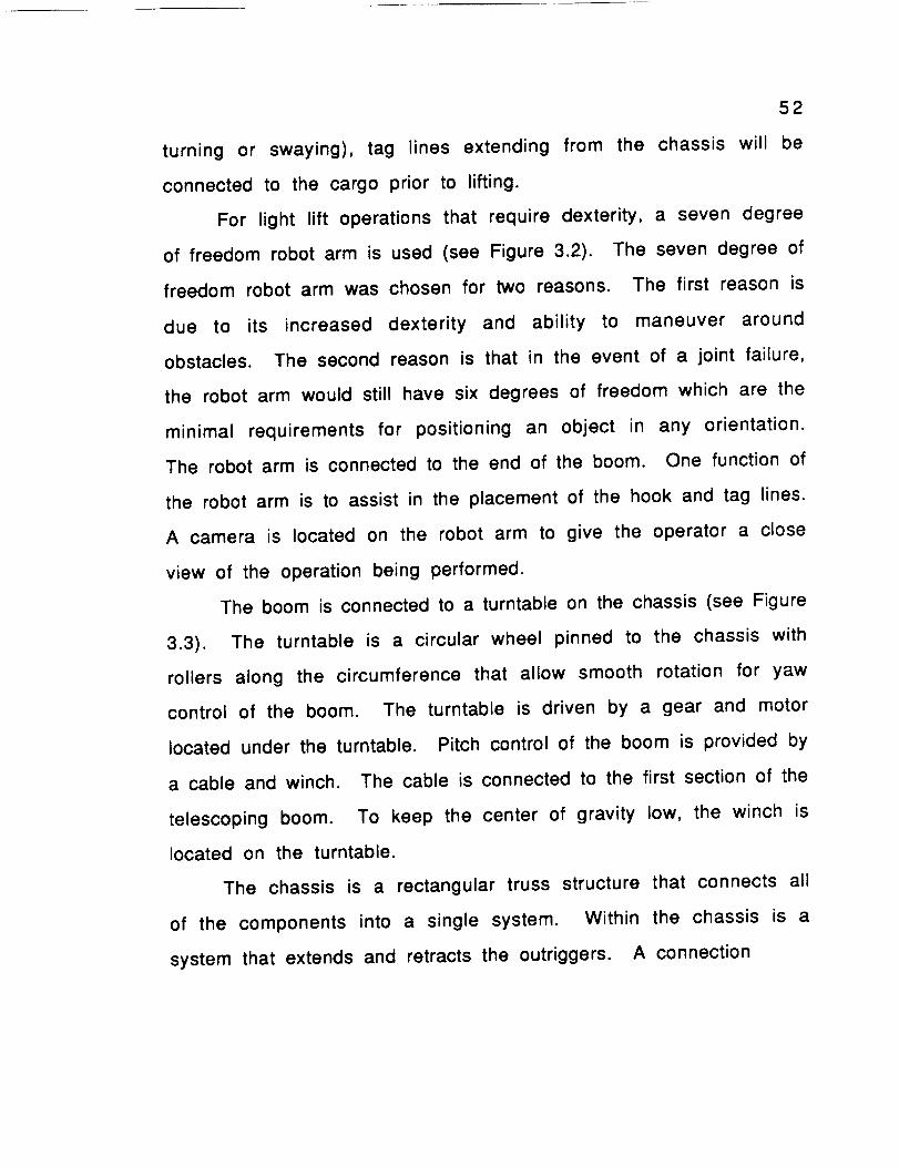
For light lift operations that require dexterity, a seven degree
of freedom robot arm is used (see Figure 3.2). The seven degree of
freedom robot arm was chosen for two reasons. The first reason is
due to its increased dexterity and ability to maneuver around
obstacles. The second reason is that in the event of a joint failure,
the robot arm would still have six degrees of freedom which are the
minimal requirements for positioning an object in any orientation.
The robot arm is connected to the end of the boom. One function of
the robot arm is to assist in the placement of the hook and tag lines.
A camera is located on the robot arm to give the operator a close
view of the operation being performed.
The boom is connected to a turntable on the chassis (see Figure
3.3). The turntable is a circular wheel pinned to the chassis with
rollers along the circumference that allow smooth rotation for yaw
control of the boom. The turntable is driven by a gear and motor
located under the turntable. Pitch control of the boom is provided by
a cable and winch. The cable is connected to the first section of the
telescoping boom. To keep the center of gravity low, the winch is
located on the turntable.
The chassis is a rectangular truss structure that connects all
of the components into a single system. Within the chassis is a
system that extends and retracts the outriggers. A connection

53
©
ROBOTICS RESERRCH
K SERIES ROBOT RRM
SEVEN DEGREES OF FREEDOM (DOF)
F;our• 3.2: SEVEN DOF ROBOT RRM

54
R
\
©
ROLLER_
INTERVRLS
R
BOOM ATTACHMENT POINT
GERRS
CHRSSIS
SECTION RR
Figur• 3.3: TURNTRBLE

55
mechanism is included on the chassis for towing. Also located on
the chassis are two small motors that control retraction of the tag
lines.
3.2 COMPONENTS OF THE LIFTER
As a result of the decision matrices performed, the following
components have been selected to be incorporated into the final
design:
Table 1. Final Chosen Components
COMPONENTS
Boom
Robot Liftin 9 Mechanism
Cable Lifting MechanismStabilizers
Transport MediaEnergy Conversion Mechanism
CHOSEN DESIGNS
Telescopin 9
Three Jaw GripperHook
Outricjgers
Conical Shaped WheelsMotor/Generator
3.2.1 Teles_tonin_a Boom
The telescoping boom consists of three rectangular truss
sections nested within each other (see Figure 3.4). Telescoping
between the sections is provided by rollers that are located along

LU
Z0
I--0LU
5G
0'}ZO
l--(JW03
Z
(I.O(_}03W_JWI-.
r_i-
o
r'_ZE:
00O2
Qm
CO
(.
O)
L_.

57
the corner members. Extension of the sections is provided by a cable
and pulley system driven by a winch located within the chassis. A
locking mechanism is located on each section so that the extension
of each section can be controlled and the sections will be held
securely during lifting operations. Retraction of the boom will be
accomplished by the retrieval of the main lifting cable. When the
hook is drawn to the end of the boom, it will hit a stop and cause the
sections to be pulled into the retracted position. Design and
analysis of the boom is found in Appendix C.
_,2.2 Three Jaw Gripper
A simplified three jaw gripper was chosen as the end effector
for the robot arm for light dextrous lifting (see Figure 3.5).
Contrary to the gripper proposed in Section 2.2.2.1.2, the jaws are
not individually rotatable. The jaws are inserted into a receptacle
and expand radially outward into slots in the receptacle wall
providing a secure connection. The jaw positions are controlled by a
motor and threaded disk system similar to a lathe chuck. The jaws
are also capable of grasping other objects without receptacles such
as tubular shapes or objects with a protrusion.

al
,II/ (I;
X I/
_ O
I" I_1 " 7 (.I
C.I _ ii i,i
-,T
[_ '" .,,-4
58
WO.O.
--j
bJW
II--
I ¸
im
in
o
ml

59
A hook was chosen as the end effector for the cable for heavy
lift operations (see Figure 3.6). The hook consists of a laminated
plate construction. This construction increases the reliability of
the hook because a crack in one plate will not propagate through to
the next plate. The hook requires a receptacle on the object to be
lifted.
3.2.4 Qutriqqers
Four telescoping outriggers are used as the stabilizing
mechanism for the lunar lifter. The lifter is stabilized by extending
the outriggers and foot pads causing the chassis to lift off of the
lunar surface.
Each outrigger consists of three rectangular truss sections
nested within each other located at each corner of the chassis. The
outriggers extend at 135 degree angles from the chassis walls.
Extension and retraction of the outriggers is provided by a pulley and
cable system that operates in the same way as the boom's (see
Figure 3.4). This pulley and cable system is located within the
chassis. A separate motor for each outrigger will power the pulley
and cable system. In case of motor failure, the outriggers may be
operated manually by a hand crank.
Telescoping between the chassis and outriggers is provided by
rollers that are located on guides within the chassis. Solenoid

,= - 60
CABLE
SPHERE
SWIVELING
CONNECTION
\0
0
BOLTS OR RIVETS
LRnINRTED
PLRTE
CONSTRUCTION
Figure 3.6: HOOK DETAIL

61
operated locking mechanisms are located on the guides and are used
to lock the outriggers at desired locations.
Attached to the ends of the outriggers are foot pads (see
Figure 3.7). The foot pads extend and retract vertically via a motor
and worm gear system. An sensor will provide feedback to the
operator to check that the chassis is level before the lifting
operation begins. Analysis of the outriggers is found in Appendix D.
3.2.5 Conical Wheels
Conical shaped wheels were selected to permit the lifter to be
towed on the lunar surface (see Figure 3.8). The wheels are a non-
inflatable design with hollow rims and have a suitable tread
covering the surfaces that will contact the ground. Two wheels are
connected to the chassis via an axle and spring damper suspension
system. The wheels are covered by fenders attached to the chassis
to protect the lifter from regolith.
3.2.6 Motor/Generator
The motors described in this section will also act as
generators to convert the potential energy of the raised payload to
electrical energy that can be stored in the energy supply vehicle.
Two motor/generators are connected to the chassis next to the base
of the boom. One of these motors powers the cable and hook system
that lifts the cargo. This motor/generator has an output of six

62
END OF TELESCOPING
SECTIONS 7
/SCREWJRCK OPERRTIOH
FOOTPRD
WORM
GERR
MOTOR
KEYWRY
-/GERR
-iI
Figure 3.7: OUTRIGGER FOOTPAD DETAIL

o
_tmJO0I- XWW_b6
-r-r
0
rW m.mQ. _-.
m-e
b
Z hi
n,, (/)a. 3(/) (/)
/
d
IIIIII
Z0I--I
(,0ZLI.JO.(,0::3(,0
QZ0::
O0,_1LI.IILl"r"
IIQ
OO
CO
(.:1
_m
LL
63

64
horsepower and is capable of lifting cargo at a rate of one meter per
second. The other motor/generator powers the boom. It has an
output of 5 horsepower and is capable of lifting the boom at an
average rate of one half a degree per second.
3.3 OTHER DESIGN CONSIDERATIONS
3.3.1 Protection System
The lifter is protected from the harsh lunar environment (e.g.
thermal effects and micrometeorite bombardment) by a protection
system (see Figure 3.9). This protection system is intended for
short term exposures. For long term storage of the lunar lifter, a
protective shelter is assumed to be available. A possible material
for the protection system is multilayered insulation covered with
layers of aluminized mylar. This protective material was chosen by
the NASA team working on the design of a micrometeorite and
thermal protection system. The protection system covering the
boom, outriggers, and boom lifting cable is of an accordion design to
allow for boom extension and retraction and is capable of being
opened at the seam to allow for maintenance of the boom. The
chassis, wheels, and outriggers are also protected by nearly the
same protection system as the boom. The only major difference is
that this protection system lacks the accordion design.

RETRRCTED _ 65
OUTRIGGER 7
RETRRCTED
Figure 3.9: PROTECTION SYSTEM

66
3.3.2 Tel_ooeratiorl System
In compliance with the design criteria, the lifter is controlled
by teleoperations by a person either in a pressurized vehicle, in a
extravehicular activity (EVA) suit, or at the lunar base. All
teleoperations are performed via a control pad and radio network
(see Figure 3.10). The control pad is a device separate from the
lifter that contains joysticks. By movement of the joysticks, a crew
member is able to control the operations of the lunar lifter.
Separate joysticks control each component of the lifter. The radio
network transmits the commands induced by the joysticks to a radio
receiving network located within the lifter. The radio receiving
network transmits the commands to the separate lifter components.
3.3.3 Dismount from Lander
The lunar lifter will be one of the first pieces of equipment
sent to the moon. Without a lunar lifter already present on the
lunar surface, the lifter must be capable of dismounting itself from
the lunar lander. The lifter will dismount on a ramp incorporated
onto the lander (see Figure 3.11). The robot arm is used in
conjunction with the tag lines to lower the lifter down the ramp to
the lunar surface.

VIDEO CRMERR
TRRNSMZTER
BOOMRCTURTORS
ROBOT
ROBOTCONTROLLER
?FORCE FEEDBRCK
TRRNSMITTER
67
FOOTPRD
RCTURTORS
CRBLEWINCH
RCTURTOR
RECEIVER
OUTRIGGER
RCTURTORS
?TRRNSMITER
CONTROL
I RECIEVER
BOX J
F;our• 3. 10: TELEOPERRTIONS SCHErlRTIC

68
a¢wQz
..i
0rip,i,
k-Z
0s'-O_
Q
SO
L
l,

69
3.4 SUMMARY OF DESIGN SOLUTION
Resulting from the decision matrices, the team selected an
overall design as well as its major components. The overall design
is a variable angle crane and the major components are the
telescoping boom, the robotic arm with three jaw gripper, the cable
with hook, the stabilizing outriggers, the conical wheels, and the
motor/generator. The specifications for the lunar lifter and its
components are in Appendix E.

CONCLUSION AND RECOMMENDATIONS
USRA and NASA are sponsoring the development of specialized
equipment that will assist in the establishment of a manned lunar
base. Our design team was asked to design a versatile lifting
machine for lunar base operations.
alternate designs for the overall
machine and for its major components.
The team developed several
configuration of the lifting
The final chosen design is a variable angle crane with a
compactable, telescoping boom. This final design meets the stated
design requirements and criteria as explained below.
The crane is capable of lifting heavy loads by a cable and hook
suspended from the end of the boom. The crane is also capable of
light, dextrous lifts by a robot arm with a three jaw gripper. The
robot arm has a camera to give visual feedback to the operator. Two
conical shaped wheels attached to the chassis allow the crane to be
towed on the lunar surface by a separate vehicle. Power for the
lifter is supplied by a separate energy source.
Four retractable outriggers extend from the chassis to
stabilize the crane during lifting operations. The outriggers, as well
as the boom and chassis, are truss structures to minimize weight
and to increase accessibility of internal components for
maintenance or repair. Motor/generators are used to minimize
7O

71
power consumption. The lifter is teleoperated by one person using
joysticks and a video monitor.
The design team has developed an overall design for the lunar
lifter and its components. The structural sizes determined by the
design team are approximate. Further analysis is needed to
determine the optimum design dimensions of the lifter and its
components•
The design team recommends that following steps for further
design of the lifter and its components:
•
2.
3.
4.
5.
6.
7.
8.
9.
detailed stress analysis,
materials selection process,
design or selection of suitable teleoperations hardware,
design of a protection system,
design of a suspension system,
selection of more precise motor sizings,
gear train analysis,
design of the robot arm,
development of motion programming, and
10. development of a force feedback control system.

BIBLIOGRAPHY
72
1. "Lunar Base Environment Report", Eagle Engineering Incorporated;
Kennedy Space Center, July 1989.
2. "Design of a Lunar Colony", University of Houston, MSC and Rice
University; NASA/ASEE System Design Institute, 1972.
3. Gere, James M., Mechanics 9f Materials, second edition, PWS
Engineering, Boston, Massachusetts, 1984, pp. 200-210, 350-390.
4. "Lunar Lander Conceptual Design", Eagle Engineering, Inc.,
Houston, Texas, NASA Contract NAS9-17878.
5. Land, Peter, "Lunar Base Design", Lunar Bases and Space Activities
of the 21st Century, Mendell, W.W. (ed), Lunar and Planetary
Institute, Houston, TX, 1985.
6. Eismann, P.H., Farrell J.D., Karlen, J.P., Thompson, J.M., Vold, H.I., "A
17 Degree of Freedom Anthropomorphic Manipulator", Robotics
Research Corporation.

73
7. Bryant, C., Davis, G.W., Hooker, M., Lebigot, N., Wordtvedt, B., "The
Lunar Split Mission: A Robot Constructed Lunar Base Scenario",
NASA/USRA Advanced Space Design Program, August, 1988.
8. Freeman, R., Professor of Mechanical Engineering, The University
of Texas at Austin, (512) 471-6546.
9. Gere and Timoshenko, M¢¢hani¢_ 9f Materials. second edition,
Brooks/Cole Engineering Division, 1984.
10. Robotics Research Group, "The Development and Demonstration
of a Class of Modular, Dextrous, Medium Capacity, Force
Reflecting Manipulator Structures", The University of Texas at
Austin, August, 1989.
11. Kogan, Josef, Crane Design Theory and Ci_lculation_ of Reliability,
John Wiley and Sons, New York, 1976.

APPENDICES

APPENDIX A
PHYSICAL CHARACTERISTICS OF
THE EARTH AND MOON

A1
PHYSICAL CHARACTERISTICS OF THE EARTH AND MOON
CHARACTERISTICS MOON EARTH
Diameter 3476 km 12756 km
Mass
Density
Gravity
Escape Velocity
Length of Day
Mean Surface Temp.
Magnetic Field
Seismic Energy
7.4 x 10²² kg
3.34 g/cm 3
1.62 m/s 2
6.0 x 1024 kg
5.11 g/cm 3
9.81 m/s 2
2.38 km/s 11.18 km/s
27 days, 7 hrs, 27 min
108 ° C (day)
-150oc (night)
negligible
2 x 10⁶ joules/yr
23 hrs, 56 min
22 ° C
0.5 gauss
5 x 10 7 ]oules/yr

APPENDIX B
DECISION MATRICES

DECISIONB1
MATRIXCRITERIAWEIGHTINGFACTORS
CRITERIA • - -CONSIDEREOFALLY_ARKSI0FALWEIGHINGFACFOR
RELIABILITY ******** 8 e/45 : o.i_7s
COMPACTNESS* 1 4/4s - e.eeea
WE I GHT ***** 5 5/45 - O. 1111
SAFETY ********* 9 9/45 = e.eeoo
SIMPLICITY OFOPERATION *** 3 s/4s : e.ess?
SIMPLICITY OFDES I GN * 1 1/45 : 8.8222
im
ENERGY• *** 4 4/45 : 8. 8889
!EFFICIENCY
DURABILITY . I 1/45 = e.ea2aL, ,,
VERSATILITY ****** 6 8/45 = 0. 1333
REPAIRABILITY ******* 7 ?/45 : o. 1556
ml i
45 TOTAL SUM : 1.880

B2
OVERALLDESIGNDECISIONMATRIXOES IGN PARAMETERS
_x, _ALTERNATES _
\>.\
RELIABILITY
COMPACTNESS
WEIGHT
SAFETY
SIMPLICITY OF
OPERATION
SIMPLICITY OFDESIGN
ENERGY
EFFICIENCY
BURRBILITY,L
VERSRTILITYi
REPAIRABILITY
SUM owPRODUCTS [
• ?e?/. 942/I_ . ?eT_.-"
•178 ,/s.e/8.ej/6.e
.822 ../s.e / 3.e /s.e88?/ _t44/. 558/
•111/_._ _/,._ _/_._i1.6_ f1" / 1 8e
• 022 i/e.o _./10.0/s.o
• 534/.667// SOe/
• 067 ._/e.e _/te e_/s.e
e22 _ee/ 222/!. 2oe//"/ze. s
.711/ .711/• _/18.0
• 133 _, /3.e /s.e
• 156 ,'/S'e r,,/3.e ,,,,_, e
• 000 T. esa s.sTs 4.'t-t3

BOOM DECISION MSTRIX
B3
_RLTERNRTES
RELIABILITY
COMPACTNESS
WEIGHT
SAFETY
$1gPLICITYOF;
OPERATION
SIMPLICITYOFDESIGN
ENERGY
EFFICIENCY
DURABILITY
VERSATILITY
REPAIRABILITY
SUM OFPRODUCTS
DESIGN PARAMETERS
(j")CO
r"v"
Z
___JC_L.i_
Z
r_L.J..I..__.Jl_J_JF.----
• 118 / s.e / e.e / e.s/ e.e
. e_a/,/ t 33_'" 178_., -/
• 2ee /?.e / s.e ,,/e.e
089 ._/s.e _/s.e / ?.e ,_/e.e133 / z.e _,/?.e / s.e ,/s.s
156_/?.0 ,,/6.e ,,/#.e ,/5.0
L,008 T,336 T.202 T.35T ?.298

B4
ROBOTENDEFFECTORDECISIONMRTRI×
'_RLTERHRTES
%\--.
DES I GI_ _;>_ ,,"_\
, \ \RELIABILITY• I?8
COMPRCTNESS. g22
WEIGHT
SAFETY
SlflPLIC[TY OF
OPERRTION
S[_L[C[TY OFDESIGN
ENERGY
EFFICIENCY
OURR8[LITY
VERSRTILITY
REPRIRRBILITY
SUM OFPRODUCTS
DESIGN PRRRMETERS
..__lL..LJ.._.J__JCIZ
CE:
C]:Z
L..L.JL..L_I
...J_I-----
I.-..----IIIZC:::)
C]::::1:::l:3
I. gee 5.846 ?.sqs s.?s3
1,2_ 1.q_ 1,6e2_ ,/
• l?y
• 111 .e /7. a
._/I I. 6ee//1. see//• 2ee e ,,,/e.e/s.e
• _9,0
• '467/// . ttgg/. 6gg/
if"
• g67 ,,/-v.e/6.e i/s.e
L?_ t788_,6. L78_""• 8..:•__ -__ ._/-
• ,..//" 9,0
• 133 _/9.e
.156 _ :__

B5
CABLEENDEFFECTORDECISIONMATRIX
_,ALTERNATES
DESIGN PARAMETERS
CZ)(ZZ)-T-
.___I___I
rnr-_
El I
I---i.
I---I--I
L..L.I
RELIRBILITY
COMPRCTNESS
WEIGHT
SRFETY
SIflPLICITY OF
OPERRTION
S[flPLICITY OFDESIGN
ENERGY
EFFICIENCY
DURRBILITY
VERSRTILITY
IEPAIRABILITY
SUM OF
PRODUCTS
.17B
.022
.III
.200
.022
.067
.022
.089
.133
.156
8. 958 ½.734

B6
STABILIZERDECISIONMRTRI×
R,_,,ALTERNATES
DESIGN PARAMETERS
n , n
z
C.r"3
I----
C_
"i--"
Z
n , t
z
--r--
l-..-
IELIRBILITY. 178
:OMPACTNESS.022
JE IGHT .111
;AFETY .200
SII1M.ICITYOF
OPERATION •022
SI_LICITY OFDES I GH .06?
ENERGY
EFFICIENCY .022
DURABILITY • 089
VERSBTILITY • 133
IEPRIRABILITY. 156
;UM OFPRODUCTS • S. SSe 8. 290 5. 112 7.62q ?. 158

B7
TRANSPORTMEDIA DECISION MATRIX
'_RLTERNATES
%\---*
DESIGN PARAMETERS
.___J
Z
I-----ZL..J._I
Z
L_2_JZCZZ_
C2ZZ
I----
tELIRBILITY • 178
COflPflCTNESS• 822
WEIGHT .111
SRFETY .288
SInPLICIW OF
OPERRTION , 822
S[flPLICITY OFDESIGN .0S7
ENERGY
EFFICIENCY .822
OURflBILITY . 889
VERSRTIL]TY . 133
REPAIRABILITY. 156
SUM OF
PROOUCTS 5.q89
l_.¢..J.__._J
z
__...J
p---
I------

B8
ENERGYCONVERSIONDECISIONMATRIX
DESI
CRITER
ALTERNATES
DESIGN PARAMETERS
RELIABILITY. I?8
COMPACTNESS. 022
WE IGHT . I I I
SAFETY .288
SINPLICITYOFOPERATION .022
SIMPLICITY OFDESIGN .067
ENERGY
EFFICIENCY ,022
DURABILITY .089
VERSRTILITY. 133
178
5.739
EPAIRABILITY. 15G
SUM OFPRODUCTS . B 0 6.668

APPENDIX C
BOOM ANALYSIS

BOOM LENGTH
CI
ASSUME
5X5 CHRSSIS
\
'\_/_// I-_ j_. \
2.5 I 7
8,4
fL"'_/18.5 2+ 9.4 2
L:I4 m
_---- ___ SRY
I
5
Ii
15 METERS
5
dEZ-_-ZT:-2L_-q
->ILl
5
COMPRCTED
G
----7
FJII
i
O--:,,-,,,'-:"_ P_qE L,,3
OF POOR QUALITY

BOOM LORD ANALYSISC2
T
A
I
T - VERTICAL COMPONENT
OF CABLE FORCE
P - WEIGHT OF LIFTEDCARGO
I
P
TO SIMPLIFY CALCULATIONS THE BOOM WAS
CONSIDERED TO BE ONE SECTION
LOADED AS SHOWN
, ! I
T
#l p At
THE MAXIMUM DEFLECTION IN THE BOOM
IS DETERMINED BY THE FOLLOWING FORMULA:
= PB(_ - Be) _
9:P_LEI
E - YOUNGS MODULUS
I - MOMENT OF INERTIA
P CAN BE DEFINED IN TERMS OF T
BY SUMMING THE MOMENTS ABOUT THE LEFT END.
P=TR/L L - OVERRLL LENGTH
ORIGINAL PAGE IS
OF POOR QUALITY

ESTIMATION OF MOMENT OF INERTIA FOR THE TRUSS
STRUCTURE BOOM,
C3
BOOM CROSS SECTION
IGNORING ANGLED
MEMBERS OF TRUSS
( CONSERVATIVE )
THE MOMENT OF INERTIA OF R CROSS SECTION
OF THE BOOM WAS DETERMINED BY USING
THE METHOD OF COMPOSITES AND THE PARALLEL
AXIS THEOREM.W
F 7_- r---7u
H ....... _ X
L-dT
I=x= Itx- Iex
•-(_"+ Ao_)-1"n'R"\Iz F_
= T4 - frR4_- T_
SHAPE 3 IS THEN MOVED BY PARALLEL AXIS THEOREM
I3 =[T*-ITR41+ F_
_- IT 4(_q' I-_)+( Te- Ir_I_e)(_-T>2
ITmrm.= 4 18

C4
ESTIMATION OF MASS OF BOOM
ASSUME: ANGLED MEMBERS OF TRUSS ARE AT ½5 DEGREES
W
L_J__i
SECTION RA
# ANGLED MEMBERS
: LX½1H
# VERTICAL MEMBERS
: LX#IH
FOR THE WEIGHT ESTIMATION THE BOOM WAS
CONSIDERED WHOLE (NOT IN SECTIONS) WITH THE
ABOVE LISTED NUMBER OF MEMBERS.
FOR LEGTHWISE MEMBERS;
VOLUME: LT2-_R2L
FOR ANGLED AND VERTICAL MEMBERS;
VOLUME=LXWXT
THE MASS OF THE BOOM IS THEN THE TOTAL
VOLUME OF MATERIAL TIMES ITS DENSITY
FOR THE ESTIMATION, ALUMINUM WAS CHOSEN.
A BASIC PROGRAM WAS WRITTEN TO DETERMINE
THE MAXIMUM DEFLECTION AND THE MASS OF THE BOOM.

C5

C8
USING THIS PROGRAM, ITERATION OF THE CROSS
SECTION DIMENSIONS WERE PERFORMED UNTIL R
DESIREABLE DEFLECTION AND MASS _RS OBTAINED.
THE FOLLOWING VALUES WERE CHOSEN:
H = 8.75m
N -- 0.5 m
T = 0.08m
R = 0.8?5 m
THESE VALUES RESULTED IN THE FOLLONING:
MAX DEFLECTION = 8C,I_MAX STRESS = 2.13 ,-, 0 P(,
MASS = _20 Kg
THE RESULTING DEFLECTION WAS ACCEPTED
FOR TWO MAIN REASONS:
I •
2.
IT IS SMALL COMPARED TO THE LENGTH
THE ACTUAL DEFLECTION WOULD BE LESS
SINCE THE ESTIMATED MOMENT OF INERTIA IS
BELIEVED TO BE LOWER THAN THE ACTUAL

APPENDIX D
OUTRIGGER ANALYSIS

OUTRIGGER SIZING
DI
IN ORDER TO PERFORM THE OUTRIGGER SIZING
CALCULATIONS, THE OVERRLL WEIGHT OF THE LIFTER
HRD TO BE ESTIMRTED.
BELOW ARE APPROXIMATE VALUES OF MASS FOR SEVERAL
COMPONENTS,
BOOM AND ITS RIGGING
CHASSIS
OUTRIGGERS _ FOOTPADS
ALL MOTORS
TURNTABLE
WHEELS
ROBOT ARM
TOTAL MASS
G88 Kg
G00 Kg
2488 K9
388 K@
280 K_
288 Kg
108 K9
4488 Ke
ASSUMING THE CENTER OF GRAVITY TO BE
IN THE GEOMETRIC CENTER OF THE LIFTER, THE
ANALYSIS IS AS FOLLOWS:
TO MINIMIZE MOMENT LORDING, THE LIFTER
IS POSITIONED AS CLOSE AS POSSIBLE TO LANDER,
THE DISTANCE FROM R TO B
IS ABOUT 10.5 mGIVEN R 5m SQUARE CHASSISAND Im CLEARANCEBETWEEN LIFTER CHASSISAND LANDER FOOT,
GL E)"-, /
13 -.e--- LANDER
///,,, _
(_ ',- ..... LIFTER

D2
B
BOOM
L ,i
,f
.Jr"
/
J
/"
10.5m
i
JiA
IW P
W - WEIGHT OF LIFTER
P - RERCTION RT FOOTPRD
L - DISTRNCE TO FOOTPRD
F - WEIGHT OF HRBITRTION MODULE
SUMMING THE MOMENTS RBOUT PT R. RND B.
L : 10.5F/(W+F) P : 10.5F/L
RTURL OUTRIGGER LENGTH BY GEOMETRY IS:
L/COS(45)-3.5
_k-1/2 CHRSSIS DIRGONRL
THE CROSS SECTIONRL SHRPE OF THE OUTRIGGERS
WRS CHOSEN TO BE THE SRME RS THE BOOM.
INITIRL CRLCULRTIONS REVERLED THE OUTRIGGERS
WOULD EXTEND RS FAR RS TEN METERS.
THEREFORE, THEY WERE DESIGNED TO TELESCOPE
£S THE BOOM.

D3

D4
BECRUSE THE SIZE OF THE OUTRIGGERS RFFECTS THE
OVERRLL MRSS OF THE LIFTER, THE CRLCULRTIONS FOR
THE OUTRIGGER LENGTH WERE ITERRTIVELY PERFORMED
BY R BRSIC PROGRRM. (LISTING ON NEXT PRGE)
RS WITH THE BOOM, THE OUTRIGGERS WERE NOT
CONSIDERED RS SECTIONED.
THE OUTRIGGERS WERE MODELED RS R CRTILEVER BERM
LORDED RT THE END.
THE RESULTING OUTRIGGER DIMENSIONS RND LORD RESPONSE
RRE RS FOLLOWS:
LENGTH
CROSS SECTION HEIGHT
CROSS SECTION WIDTH
FLRNGE WIDTH (T)
MR×IMUM DEFLECTION
9 m
0.75 m
0.5 m
0.1 m
0.1 m
THE RESULTING DEFLECTION WRS RCCEPTED FOR
THE SRME RERSONS RS MENTIONED IN THE BOOM RNRLYSIS
IN RPPENDIX 0.

APPENDIX E
LIFTER SPECIFICATIONS

LIFTER SPECIFICRTIONS El
LIFTING CAPACITY 41,000 NEWTONS
MASS 4408 Kg
EXTENDED BOOM LENGTH 15 METERS
RETRACTED BOOM LENGTH B METERS
BOOM CROSS SECTION HEIGHT 8.75 METERS
BOOM CROSS SECTION WIDTH 0.5 METERS
CHASSIS LENGTH 5 METERS
CHASSIS WIDTH 5 METERS
CHASSIS DEPTH 0.85 METERS
EXTENDED OUTRIGGER LENGTH 10 METERS
OPERATION TERRAIN
DEPENDENT UPON WEIGHT AND ELEVATION OF CARGO
NO LORD: LIFTER WILL SLIDE BEFORE TIPPING
FULLY EXTENDED BOOM
LIFTING 41,080 N OFF A LANDER: FLAT TERRAIN