Design of a novel wheeled tensegrity robot: a comparison ... · Carreño and Post Robot.Biomim....
24
Carreño and Post Robot. Biomim. (2018) 5:1 https://doi.org/10.1186/s40638-018-0084-8 RESEARCH Design of a novel wheeled tensegrity robot: a comparison of tensegrity concepts and a prototype for travelling air ducts Francisco Carreño and Mark A. Post * Abstract Efforts in the research of tensegrity structures applied to mobile robots have recently been focused on a purely tensegrity solution to all design requirements. Locomotion systems based on tensegrity structures are currently slow and complex to control. Although wheeled locomotion provides better efficiency over distances there is no litera- ture available on the value of wheeled methods with respect to tensegrity designs, nor on how to transition from a tensegrity structure to a fixed structure in mobile robotics. This paper is the first part of a larger study that aims to combine the flexibility, light weight, and strength of a tensegrity structure with the efficiency and simple control of a wheeled locomotion system. It focuses on comparing different types of tensegrity structure for applicability to a mobile robot, and experimentally finding an appropriate transitional region from a tensegrity structure to a conven- tional fixed structure on mobile robots. It applies this transitional structure to what is, to the authors’ knowledge, the design of the world’s first wheeled tensegrity robot that has been designed with the goal of traversing air ducts. Keywords: Bio-inspired robots, Tensegrity, Wheeled mobility © The Author(s) 2018. This article is distributed under the terms of the Creative Commons Attribution 4.0 International License (http://creativecommons.org/licenses/by/4.0/), which permits unrestricted use, distribution, and reproduction in any medium, provided you give appropriate credit to the original author(s) and the source, provide a link to the Creative Commons license, and indicate if changes were made. Background A tensegrity structure is comprised of elastic elements and rigid elements that interact so the structure extends over a space larger than the space of its individual parts. e sum of the forces between all its parts is zero; there- fore, the structure is in equilibrium without the need of external forces. All elastic elements bear exclusively ten- sional force, but not all tensional elements are elastic. e most spread-out use of rigid and elastic elements is struts and cables, respectively. e “Needle Tower” (Fig. 1) is made of aluminium struts and steel cables. e struts are suspended in the air held only by these cables. e structure rises with its internal energy compensating its potential energy. e first tensegrity structure was made by Latvian artist Karl Ioganson. It was shown in an exhi- bition in 1921 as part of his “Cold Structures” in the early Constructivism movement. Categorised at the time as a “Spatial Construction” (Fig. 2), the structure made is currently known as a 3-strut prism or triangular prism. Unfortunately, there was no further development of the novel structural principle [1]. Tensegrity structures were rediscovered by sculptor Kenneth Snelson who created “X Piece” (also known as “Early X piece”) in 1948 when he was still a student [2]. His professor, Buckminster Fuller, “asked Mr. Snelson to make a variation on “Early X Piece”, which he later exhibited—without crediting his student—at an important exhibition at the Museum of Modern Art in 1959” [3]. ey both ended up fill- ing patents to claim authorship in 1959 (patent number 3.063.521 granted on 1962 to Fuller) and 1960 (patent number 3.169.611 granted in 1965 to Snelson). ere is also a patent (number 1.377.290) granted to Emmerich in France in 1963 [4]. e word tensegrity originated as the hyphenated word tensile-integrity structure, coined by Fuller in his patent. Similarly, Snelson coined the name continuous tension, discontinuous compression struc- tures in his own patent. Tensegrity structures eventually expanded beyond art into engineering. Many studies have been done in stat- ics, kinematics, dynamics, and biology. e main fields Open Access *Correspondence: [email protected] Department of Design, Manufacture, and Engineering Management, University of Strathclyde, 75 Montrose Street, Glasgow G1 1XJ, UK
-
Upload
vuongquynh -
Category
Documents
-
view
221 -
download
0
Transcript of Design of a novel wheeled tensegrity robot: a comparison ... · Carreño and Post Robot.Biomim....
Carreño and Post Robot. Biomim. (2018) 5:1 https://doi.org/10.1186/s40638-018-0084-8
RESEARCH
Design of a novel wheeled tensegrity robot: a comparison of tensegrity concepts and a prototype for travelling air ductsFrancisco Carreño and Mark A. Post*
Abstract
Efforts in the research of tensegrity structures applied to mobile robots have recently been focused on a purely tensegrity solution to all design requirements. Locomotion systems based on tensegrity structures are currently slow and complex to control. Although wheeled locomotion provides better efficiency over distances there is no litera-ture available on the value of wheeled methods with respect to tensegrity designs, nor on how to transition from a tensegrity structure to a fixed structure in mobile robotics. This paper is the first part of a larger study that aims to combine the flexibility, light weight, and strength of a tensegrity structure with the efficiency and simple control of a wheeled locomotion system. It focuses on comparing different types of tensegrity structure for applicability to a mobile robot, and experimentally finding an appropriate transitional region from a tensegrity structure to a conven-tional fixed structure on mobile robots. It applies this transitional structure to what is, to the authors’ knowledge, the design of the world’s first wheeled tensegrity robot that has been designed with the goal of traversing air ducts.
Keywords: Bio-inspired robots, Tensegrity, Wheeled mobility
© The Author(s) 2018. This article is distributed under the terms of the Creative Commons Attribution 4.0 International License (http://creat iveco mmons .org/licen ses/by/4.0/), which permits unrestricted use, distribution, and reproduction in any medium, provided you give appropriate credit to the original author(s) and the source, provide a link to the Creative Commons license, and indicate if changes were made.
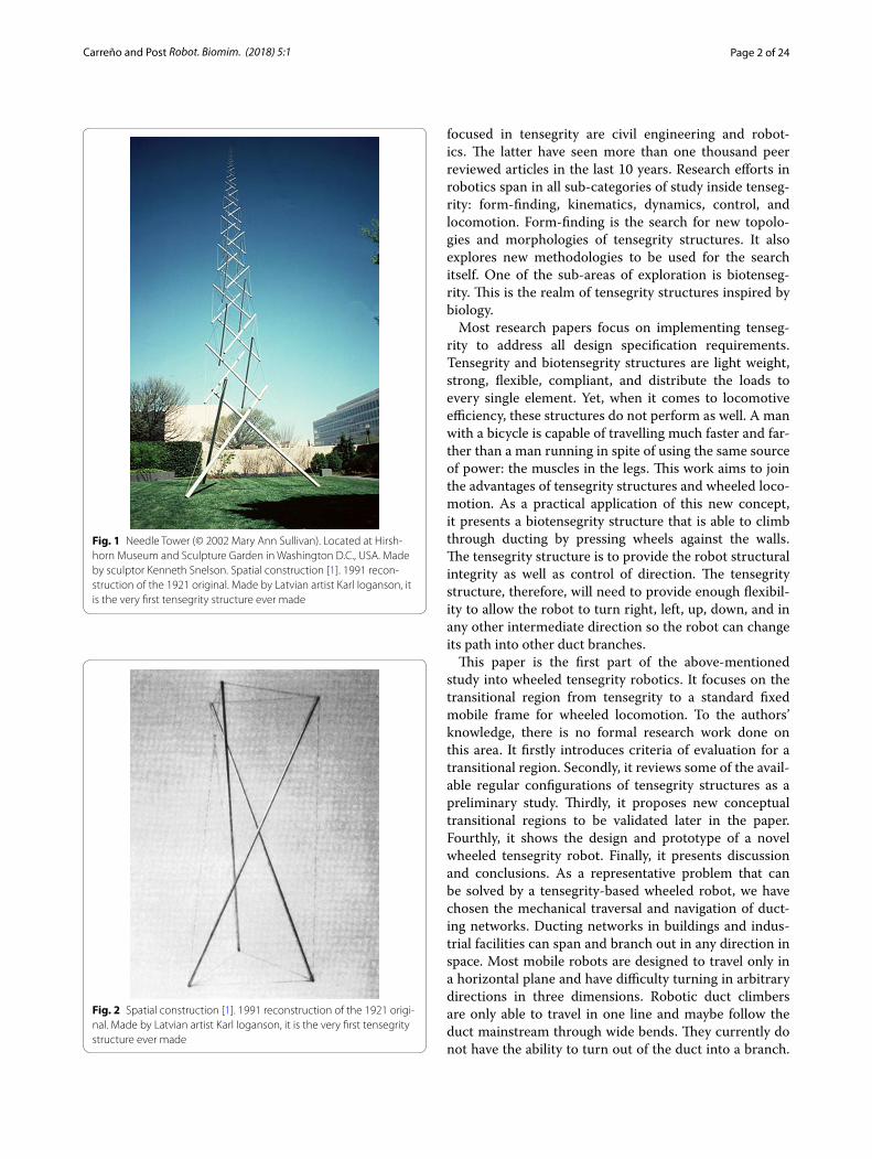
BackgroundA tensegrity structure is comprised of elastic elements and rigid elements that interact so the structure extends over a space larger than the space of its individual parts. The sum of the forces between all its parts is zero; there-fore, the structure is in equilibrium without the need of external forces. All elastic elements bear exclusively ten-sional force, but not all tensional elements are elastic. The most spread-out use of rigid and elastic elements is struts and cables, respectively. The “Needle Tower” (Fig. 1) is made of aluminium struts and steel cables. The struts are suspended in the air held only by these cables. The structure rises with its internal energy compensating its potential energy. The first tensegrity structure was made by Latvian artist Karl Ioganson. It was shown in an exhi-bition in 1921 as part of his “Cold Structures” in the early Constructivism movement. Categorised at the time as a “Spatial Construction” (Fig. 2), the structure made is
currently known as a 3-strut prism or triangular prism. Unfortunately, there was no further development of the novel structural principle [1]. Tensegrity structures were rediscovered by sculptor Kenneth Snelson who created “X Piece” (also known as “Early X piece”) in 1948 when he was still a student [2]. His professor, Buckminster Fuller, “asked Mr. Snelson to make a variation on “Early X Piece”, which he later exhibited—without crediting his student—at an important exhibition at the Museum of Modern Art in 1959” [3]. They both ended up fill-ing patents to claim authorship in 1959 (patent number 3.063.521 granted on 1962 to Fuller) and 1960 (patent number 3.169.611 granted in 1965 to Snelson). There is also a patent (number 1.377.290) granted to Emmerich in France in 1963 [4]. The word tensegrity originated as the hyphenated word tensile-integrity structure, coined by Fuller in his patent. Similarly, Snelson coined the name continuous tension, discontinuous compression struc-tures in his own patent.
Tensegrity structures eventually expanded beyond art into engineering. Many studies have been done in stat-ics, kinematics, dynamics, and biology. The main fields
Open Access
*Correspondence: [email protected] Department of Design, Manufacture, and Engineering Management, University of Strathclyde, 75 Montrose Street, Glasgow G1 1XJ, UK
Page 2 of 24Carreño and Post Robot. Biomim. (2018) 5:1
focused in tensegrity are civil engineering and robot-ics. The latter have seen more than one thousand peer reviewed articles in the last 10 years. Research efforts in robotics span in all sub-categories of study inside tenseg-rity: form-finding, kinematics, dynamics, control, and locomotion. Form-finding is the search for new topolo-gies and morphologies of tensegrity structures. It also explores new methodologies to be used for the search itself. One of the sub-areas of exploration is biotenseg-rity. This is the realm of tensegrity structures inspired by biology.
Most research papers focus on implementing tenseg-rity to address all design specification requirements. Tensegrity and biotensegrity structures are light weight, strong, flexible, compliant, and distribute the loads to every single element. Yet, when it comes to locomotive efficiency, these structures do not perform as well. A man with a bicycle is capable of travelling much faster and far-ther than a man running in spite of using the same source of power: the muscles in the legs. This work aims to join the advantages of tensegrity structures and wheeled loco-motion. As a practical application of this new concept, it presents a biotensegrity structure that is able to climb through ducting by pressing wheels against the walls. The tensegrity structure is to provide the robot structural integrity as well as control of direction. The tensegrity structure, therefore, will need to provide enough flexibil-ity to allow the robot to turn right, left, up, down, and in any other intermediate direction so the robot can change its path into other duct branches.
This paper is the first part of the above-mentioned study into wheeled tensegrity robotics. It focuses on the transitional region from tensegrity to a standard fixed mobile frame for wheeled locomotion. To the authors’ knowledge, there is no formal research work done on this area. It firstly introduces criteria of evaluation for a transitional region. Secondly, it reviews some of the avail-able regular configurations of tensegrity structures as a preliminary study. Thirdly, it proposes new conceptual transitional regions to be validated later in the paper. Fourthly, it shows the design and prototype of a novel wheeled tensegrity robot. Finally, it presents discussion and conclusions. As a representative problem that can be solved by a tensegrity-based wheeled robot, we have chosen the mechanical traversal and navigation of duct-ing networks. Ducting networks in buildings and indus-trial facilities can span and branch out in any direction in space. Most mobile robots are designed to travel only in a horizontal plane and have difficulty turning in arbitrary directions in three dimensions. Robotic duct climbers are only able to travel in one line and maybe follow the duct mainstream through wide bends. They currently do not have the ability to turn out of the duct into a branch.
Fig. 1 Needle Tower (© 2002 Mary Ann Sullivan). Located at Hirsh-horn Museum and Sculpture Garden in Washington D.C., USA. Made by sculptor Kenneth Snelson. Spatial construction [1]. 1991 recon-struction of the 1921 original. Made by Latvian artist Karl Ioganson, it is the very first tensegrity structure ever made
Fig. 2 Spatial construction [1]. 1991 reconstruction of the 1921 origi-nal. Made by Latvian artist Karl Ioganson, it is the very first tensegrity structure ever made
Page 3 of 24Carreño and Post Robot. Biomim. (2018) 5:1
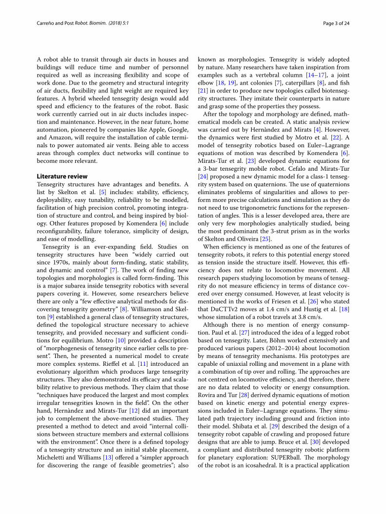
A robot able to transit through air ducts in houses and buildings will reduce time and number of personnel required as well as increasing flexibility and scope of work done. Due to the geometry and structural integrity of air ducts, flexibility and light weight are required key features. A hybrid wheeled tensegrity design would add speed and efficiency to the features of the robot. Basic work currently carried out in air ducts includes inspec-tion and maintenance. However, in the near future, home automation, pioneered by companies like Apple, Google, and Amazon, will require the installation of cable termi-nals to power automated air vents. Being able to access areas through complex duct networks will continue to become more relevant.
Literature reviewTensegrity structures have advantages and benefits. A list by Skelton et al. [5] includes: stability, efficiency, deployability, easy tunability, reliability to be modelled, facilitation of high precision control, promoting integra-tion of structure and control, and being inspired by biol-ogy. Other features proposed by Komendera [6] include reconfigurability, failure tolerance, simplicity of design, and ease of modelling.
Tensegrity is an ever-expanding field. Studies on tensegrity structures have been “widely carried out since 1970s, mainly about form-finding, static stability, and dynamic and control” [7]. The work of finding new topologies and morphologies is called form-finding. This is a major subarea inside tensegrity robotics with several papers covering it. However, some researchers believe there are only a “few effective analytical methods for dis-covering tensegrity geometry” [8]. Williamson and Skel-ton [9] established a general class of tensegrity structures, defined the topological structure necessary to achieve tensegrity, and provided necessary and sufficient condi-tions for equilibrium. Motro [10] provided a description of “morphogenesis of tensegrity since earlier cells to pre-sent”. Then, he presented a numerical model to create more complex systems. Rieffel et al. [11] introduced an evolutionary algorithm which produces large tensegrity structures. They also demonstrated its efficacy and scala-bility relative to previous methods. They claim that those “techniques have produced the largest and most complex irregular tensegrities known in the field”. On the other hand, Hernàndez and Mirats-Tur [12] did an important job to complement the above-mentioned studies. They presented a method to detect and avoid “internal colli-sions between structure members and external collisions with the environment”. Once there is a defined topology of a tensegrity structure and an initial stable placement, Micheletti and Williams [13] offered a “simpler approach for discovering the range of feasible geometries”; also
known as morphologies. Tensegrity is widely adopted by nature. Many researchers have taken inspiration from examples such as a vertebral column [14–17], a joint elbow [18, 19], ant colonies [7], caterpillars [8], and fish [21] in order to produce new topologies called biotenseg-rity structures. They imitate their counterparts in nature and grasp some of the properties they possess.
After the topology and morphology are defined, math-ematical models can be created. A static analysis review was carried out by Hernàndez and Mirats [4]. However, the dynamics were first studied by Motro et al. [22]. A model of tensegrity robotics based on Euler–Lagrange equations of motion was described by Komendera [6]. Mirats-Tur et al. [23] developed dynamic equations for a 3-bar tensegrity mobile robot. Cefalo and Mirats-Tur [24] proposed a new dynamic model for a class-1 tenseg-rity system based on quaternions. The use of quaternions eliminates problems of singularities and allows to per-form more precise calculations and simulation as they do not need to use trigonometric functions for the represen-tation of angles. This is a lesser developed area, there are only very few morphologies analytically studied, being the most predominant the 3-strut prism as in the works of Skelton and Oliveira [25].
When efficiency is mentioned as one of the features of tensegrity robots, it refers to this potential energy stored as tension inside the structure itself. However, this effi-ciency does not relate to locomotive movement. All research papers studying locomotion by means of tenseg-rity do not measure efficiency in terms of distance cov-ered over energy consumed. However, at least velocity is mentioned in the works of Friesen et al. [26] who stated that DuCTTv2 moves at 1.4 cm/s and Hustig et al. [18] whose simulation of a robot travels at 3.8 cm/s.
Although there is no mention of energy consump-tion. Paul et al. [27] introduced the idea of a legged robot based on tensegrity. Later, Böhm worked extensively and produced various papers (2012–2014) about locomotion by means of tensegrity mechanisms. His prototypes are capable of uniaxial rolling and movement in a plane with a combination of tip over and rolling. The approaches are not centred on locomotive efficiency, and therefore, there are no data related to velocity or energy consumption. Rovira and Tur [28] derived dynamic equations of motion based on kinetic energy and potential energy expres-sions included in Euler–Lagrange equations. They simu-lated path trajectory including ground and friction into their model. Shibata et al. [29] described the design of a tensegrity robot capable of crawling and proposed future designs that are able to jump. Bruce et al. [30] developed a compliant and distributed tensegrity robotic platform for planetary exploration: SUPERball. The morphology of the robot is an icosahedral. It is a practical application
Page 4 of 24Carreño and Post Robot. Biomim. (2018) 5:1
of tensegrity robotics that NASA sponsors. The paper does not focus on the locomotive part of the robot, only design. Sabelhaus et al. [31] show the construction aspect of SUPERball prototype. Friesen et al. [32] developed another practical application, a tensegrity robot capable of climbing vertical ducts. Friesen’s robot, called DuCTT (duct climbing tetrahedral tensegrity), comprises two tetrahedral frames connected by eight actuated cables. The robot holds to the duct by applying pressure against the wall with one linear actuator in each tetrahedron. It advances by moving one frame relative to the other. Researchers discuss in the paper the inverse kinematic control strategy used to actuate the robot. They point out that wheeled duct climbers can move quickly but “have difficulty overcoming sharp corners or other irregu-larities” [32] and that the use of rigid joint legs requires heavy actuators to achieve vertical ascent. Tests on this robot were included in an updated paper, but the robot is still not able to turn into a new branch. Friesen showed computer simulated work on NTRT (NASA Tensegrity Robotics Toolkit) developed by NASA to facilitate rapid design and control of tensegrity robots. Hustig et al. [18], Mirletz et al. [16], Lessard et al. [20], SunSpiral et al. [33], Bruce et al. [30], and Sabelhaus et al. [31] have also used NTRT. This software has been validated with prototypes.
Criteria of evaluationDesigning a hybrid wheeled tensegrity robot, to the authors’ knowledge, has never been attempted before. Therefore, some criteria of evaluation need to be estab-lished beforehand in order to be able to interpret the results of this study.
Antagonistic tensional elementsThe first criteria developed were meant to classify ten-sional elements in two groups: elements that produce contraction of the structure and elements that produce Expansion.
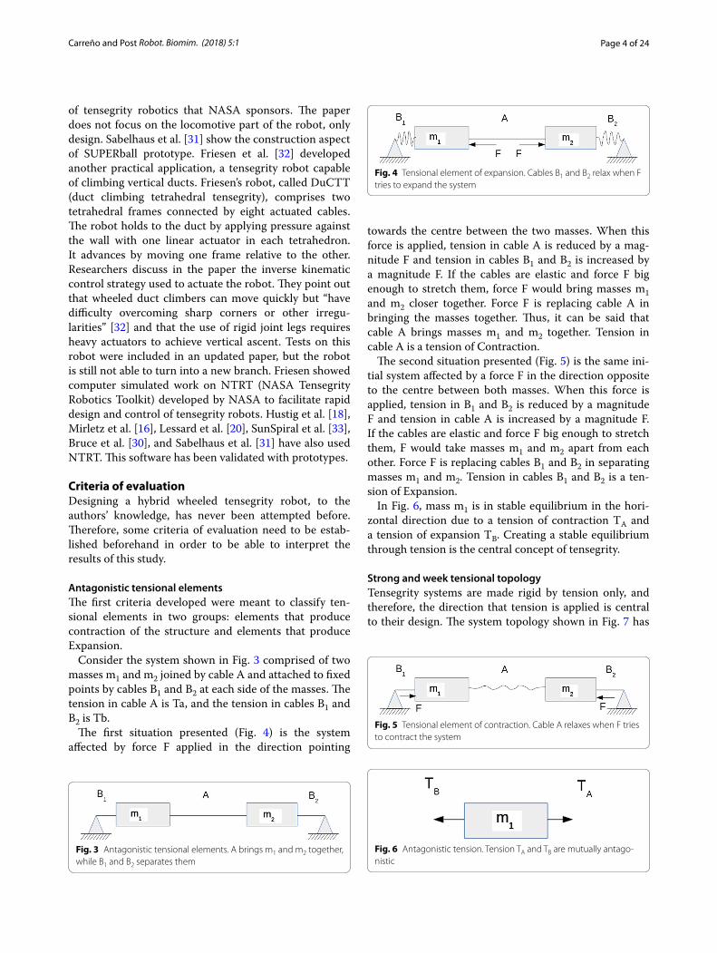
Consider the system shown in Fig. 3 comprised of two masses m1 and m2 joined by cable A and attached to fixed points by cables B1 and B2 at each side of the masses. The tension in cable A is Ta, and the tension in cables B1 and B2 is Tb.
The first situation presented (Fig. 4) is the system affected by force F applied in the direction pointing
towards the centre between the two masses. When this force is applied, tension in cable A is reduced by a mag-nitude F and tension in cables B1 and B2 is increased by a magnitude F. If the cables are elastic and force F big enough to stretch them, force F would bring masses m1 and m2 closer together. Force F is replacing cable A in bringing the masses together. Thus, it can be said that cable A brings masses m1 and m2 together. Tension in cable A is a tension of Contraction.
The second situation presented (Fig. 5) is the same ini-tial system affected by a force F in the direction opposite to the centre between both masses. When this force is applied, tension in B1 and B2 is reduced by a magnitude F and tension in cable A is increased by a magnitude F. If the cables are elastic and force F big enough to stretch them, F would take masses m1 and m2 apart from each other. Force F is replacing cables B1 and B2 in separating masses m1 and m2. Tension in cables B1 and B2 is a ten-sion of Expansion.
In Fig. 6, mass m1 is in stable equilibrium in the hori-zontal direction due to a tension of contraction TA and a tension of expansion TB. Creating a stable equilibrium through tension is the central concept of tensegrity.
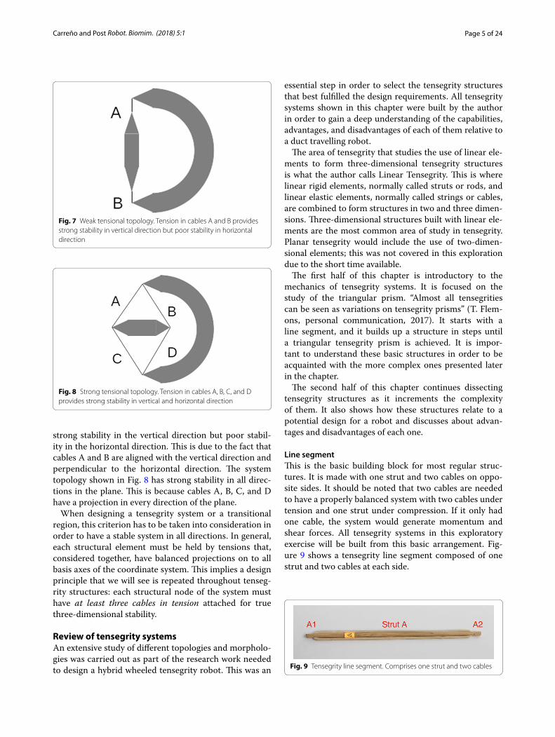
Strong and week tensional topologyTensegrity systems are made rigid by tension only, and therefore, the direction that tension is applied is central to their design. The system topology shown in Fig. 7 has
Fig. 3 Antagonistic tensional elements. A brings m1 and m2 together, while B1 and B2 separates them
Fig. 4 Tensional element of expansion. Cables B1 and B2 relax when F tries to expand the system
Fig. 5 Tensional element of contraction. Cable A relaxes when F tries to contract the system
Fig. 6 Antagonistic tension. Tension TA and TB are mutually antago-nistic
Page 5 of 24Carreño and Post Robot. Biomim. (2018) 5:1
strong stability in the vertical direction but poor stabil-ity in the horizontal direction. This is due to the fact that cables A and B are aligned with the vertical direction and perpendicular to the horizontal direction. The system topology shown in Fig. 8 has strong stability in all direc-tions in the plane. This is because cables A, B, C, and D have a projection in every direction of the plane.
When designing a tensegrity system or a transitional region, this criterion has to be taken into consideration in order to have a stable system in all directions. In general, each structural element must be held by tensions that, considered together, have balanced projections on to all basis axes of the coordinate system. This implies a design principle that we will see is repeated throughout tenseg-rity structures: each structural node of the system must have at least three cables in tension attached for true three-dimensional stability.
Review of tensegrity systemsAn extensive study of different topologies and morpholo-gies was carried out as part of the research work needed to design a hybrid wheeled tensegrity robot. This was an
essential step in order to select the tensegrity structures that best fulfilled the design requirements. All tensegrity systems shown in this chapter were built by the author in order to gain a deep understanding of the capabilities, advantages, and disadvantages of each of them relative to a duct travelling robot.
The area of tensegrity that studies the use of linear ele-ments to form three-dimensional tensegrity structures is what the author calls Linear Tensegrity. This is where linear rigid elements, normally called struts or rods, and linear elastic elements, normally called strings or cables, are combined to form structures in two and three dimen-sions. Three-dimensional structures built with linear ele-ments are the most common area of study in tensegrity. Planar tensegrity would include the use of two-dimen-sional elements; this was not covered in this exploration due to the short time available.
The first half of this chapter is introductory to the mechanics of tensegrity systems. It is focused on the study of the triangular prism. “Almost all tensegrities can be seen as variations on tensegrity prisms” (T. Flem-ons, personal communication, 2017). It starts with a line segment, and it builds up a structure in steps until a triangular tensegrity prism is achieved. It is impor-tant to understand these basic structures in order to be acquainted with the more complex ones presented later in the chapter.
The second half of this chapter continues dissecting tensegrity structures as it increments the complexity of them. It also shows how these structures relate to a potential design for a robot and discusses about advan-tages and disadvantages of each one.
Line segmentThis is the basic building block for most regular struc-tures. It is made with one strut and two cables on oppo-site sides. It should be noted that two cables are needed to have a properly balanced system with two cables under tension and one strut under compression. If it only had one cable, the system would generate momentum and shear forces. All tensegrity systems in this exploratory exercise will be built from this basic arrangement. Fig-ure 9 shows a tensegrity line segment composed of one strut and two cables at each side.
Fig. 7 Weak tensional topology. Tension in cables A and B provides strong stability in vertical direction but poor stability in horizontal direction
Fig. 8 Strong tensional topology. Tension in cables A, B, C, and D provides strong stability in vertical and horizontal direction
Fig. 9 Tensegrity line segment. Comprises one strut and two cables
Page 6 of 24Carreño and Post Robot. Biomim. (2018) 5:1
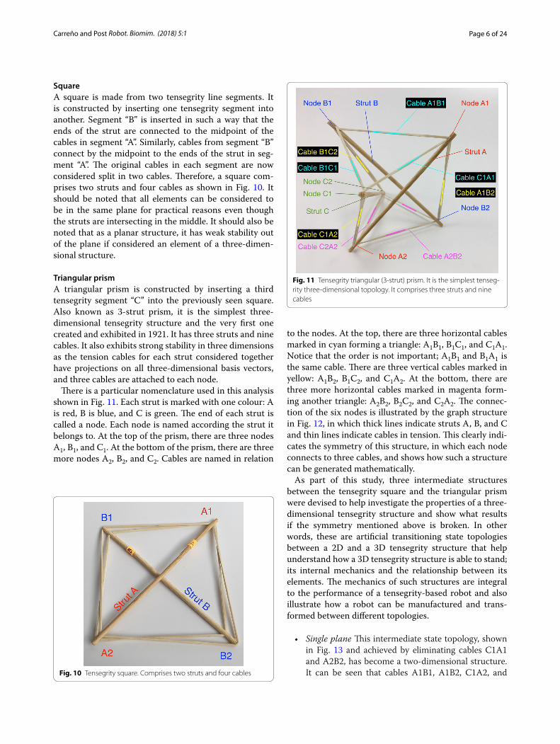
SquareA square is made from two tensegrity line segments. It is constructed by inserting one tensegrity segment into another. Segment “B” is inserted in such a way that the ends of the strut are connected to the midpoint of the cables in segment “A”. Similarly, cables from segment “B” connect by the midpoint to the ends of the strut in seg-ment “A”. The original cables in each segment are now considered split in two cables. Therefore, a square com-prises two struts and four cables as shown in Fig. 10. It should be noted that all elements can be considered to be in the same plane for practical reasons even though the struts are intersecting in the middle. It should also be noted that as a planar structure, it has weak stability out of the plane if considered an element of a three-dimen-sional structure.
Triangular prismA triangular prism is constructed by inserting a third tensegrity segment “C” into the previously seen square. Also known as 3-strut prism, it is the simplest three-dimensional tensegrity structure and the very first one created and exhibited in 1921. It has three struts and nine cables. It also exhibits strong stability in three dimensions as the tension cables for each strut considered together have projections on all three-dimensional basis vectors, and three cables are attached to each node.
There is a particular nomenclature used in this analysis shown in Fig. 11. Each strut is marked with one colour: A is red, B is blue, and C is green. The end of each strut is called a node. Each node is named according the strut it belongs to. At the top of the prism, there are three nodes A1, B1, and C1. At the bottom of the prism, there are three more nodes A2, B2, and C2. Cables are named in relation
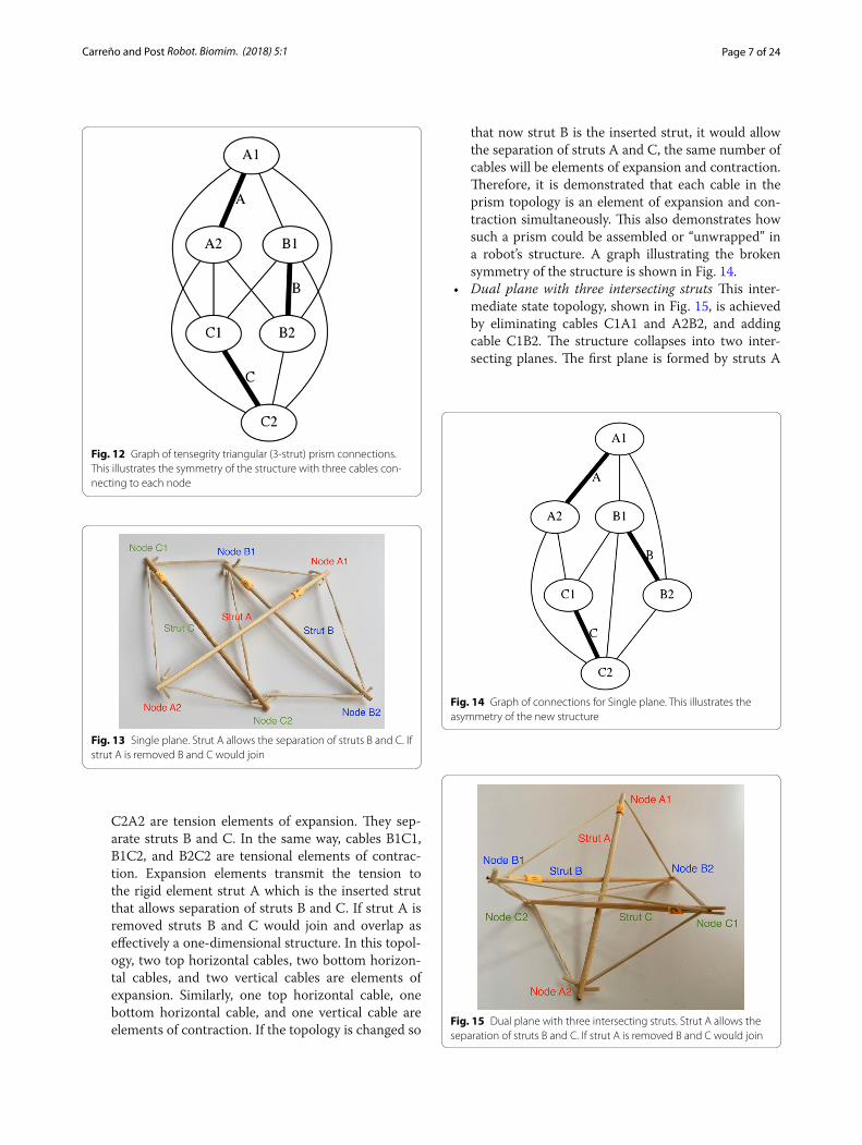
to the nodes. At the top, there are three horizontal cables marked in cyan forming a triangle: A1B1, B1C1, and C1A1. Notice that the order is not important; A1B1 and B1A1 is the same cable. There are three vertical cables marked in yellow: A1B2, B1C2, and C1A2. At the bottom, there are three more horizontal cables marked in magenta form-ing another triangle: A2B2, B2C2, and C2A2. The connec-tion of the six nodes is illustrated by the graph structure in Fig. 12, in which thick lines indicate struts A, B, and C and thin lines indicate cables in tension. This clearly indi-cates the symmetry of this structure, in which each node connects to three cables, and shows how such a structure can be generated mathematically.
As part of this study, three intermediate structures between the tensegrity square and the triangular prism were devised to help investigate the properties of a three-dimensional tensegrity structure and show what results if the symmetry mentioned above is broken. In other words, these are artificial transitioning state topologies between a 2D and a 3D tensegrity structure that help understand how a 3D tensegrity structure is able to stand; its internal mechanics and the relationship between its elements. The mechanics of such structures are integral to the performance of a tensegrity-based robot and also illustrate how a robot can be manufactured and trans-formed between different topologies.
• Single plane This intermediate state topology, shown in Fig. 13 and achieved by eliminating cables C1A1 and A2B2, has become a two-dimensional structure. It can be seen that cables A1B1, A1B2, C1A2, and Fig. 10 Tensegrity square. Comprises two struts and four cables
Fig. 11 Tensegrity triangular (3-strut) prism. It is the simplest tenseg-rity three-dimensional topology. It comprises three struts and nine cables
Page 7 of 24Carreño and Post Robot. Biomim. (2018) 5:1
C2A2 are tension elements of expansion. They sep-arate struts B and C. In the same way, cables B1C1, B1C2, and B2C2 are tensional elements of contrac-tion. Expansion elements transmit the tension to the rigid element strut A which is the inserted strut that allows separation of struts B and C. If strut A is removed struts B and C would join and overlap as effectively a one-dimensional structure. In this topol-ogy, two top horizontal cables, two bottom horizon-tal cables, and two vertical cables are elements of expansion. Similarly, one top horizontal cable, one bottom horizontal cable, and one vertical cable are elements of contraction. If the topology is changed so
that now strut B is the inserted strut, it would allow the separation of struts A and C, the same number of cables will be elements of expansion and contraction. Therefore, it is demonstrated that each cable in the prism topology is an element of expansion and con-traction simultaneously. This also demonstrates how such a prism could be assembled or “unwrapped” in a robot’s structure. A graph illustrating the broken symmetry of the structure is shown in Fig. 14.
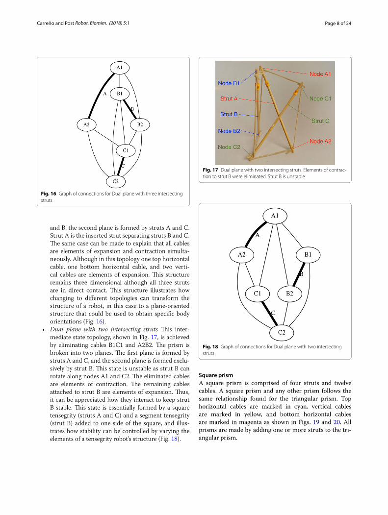
• Dual plane with three intersecting struts This inter-mediate state topology, shown in Fig. 15, is achieved by eliminating cables C1A1 and A2B2, and adding cable C1B2. The structure collapses into two inter-secting planes. The first plane is formed by struts A
Fig. 12 Graph of tensegrity triangular (3-strut) prism connections. This illustrates the symmetry of the structure with three cables con-necting to each node
Fig. 13 Single plane. Strut A allows the separation of struts B and C. If strut A is removed B and C would join
Fig. 14 Graph of connections for Single plane. This illustrates the asymmetry of the new structure
Fig. 15 Dual plane with three intersecting struts. Strut A allows the separation of struts B and C. If strut A is removed B and C would join
Page 8 of 24Carreño and Post Robot. Biomim. (2018) 5:1
and B, the second plane is formed by struts A and C. Strut A is the inserted strut separating struts B and C. The same case can be made to explain that all cables are elements of expansion and contraction simulta-neously. Although in this topology one top horizontal cable, one bottom horizontal cable, and two verti-cal cables are elements of expansion. This structure remains three-dimensional although all three struts are in direct contact. This structure illustrates how changing to different topologies can transform the structure of a robot, in this case to a plane-oriented structure that could be used to obtain specific body orientations (Fig. 16).
• Dual plane with two intersecting struts This inter-mediate state topology, shown in Fig. 17, is achieved by eliminating cables B1C1 and A2B2. The prism is broken into two planes. The first plane is formed by struts A and C, and the second plane is formed exclu-sively by strut B. This state is unstable as strut B can rotate along nodes A1 and C2. The eliminated cables are elements of contraction. The remaining cables attached to strut B are elements of expansion. Thus, it can be appreciated how they interact to keep strut B stable. This state is essentially formed by a square tensegrity (struts A and C) and a segment tensegrity (strut B) added to one side of the square, and illus-trates how stability can be controlled by varying the elements of a tensegrity robot’s structure (Fig. 18).
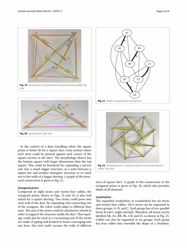
Square prismA square prism is comprised of four struts and twelve cables. A square prism and any other prism follows the same relationship found for the triangular prism. Top horizontal cables are marked in cyan, vertical cables are marked in yellow, and bottom horizontal cables are marked in magenta as shown in Figs. 19 and 20. All prisms are made by adding one or more struts to the tri-angular prism.
Fig. 16 Graph of connections for Dual plane with three intersecting struts
Fig. 17 Dual plane with two intersecting struts. Elements of contrac-tion to strut B were eliminated. Strut B is unstable
Fig. 18 Graph of connections for Dual plane with two intersecting struts
Page 9 of 24Carreño and Post Robot. Biomim. (2018) 5:1
In the context of a duct travelling robot, the square prism is better fit for a square duct cross section where each strut could be pressed against each corner of the square section in the duct. The morphology shown has the bottom square with larger dimensions than the top square. This could be beneficial for expanding a narrow axle into a much bigger structure, as a joint between a square bar and another tensegrity structure or to reach out to the walls of a bigger ducting. A graph of the struc-tural connections is given in Fig. 21.
Octagonal prismComprised of eight struts and twenty-four cables, the octagonal prism, shown in Figs. 22 and 23, is also well suited for a square ducting. Two struts could press into each wall of the duct. By expanding and contracting one of the octagons, the robot could adapt to different duct sizes. The end of the struts could be attached to wheels in order to support the structure inside the duct. This topol-ogy could also be used as a vacuuming tool. If the struts are made of piping and hooked to hoses converging into one hose, this tool could vacuum the walls of different
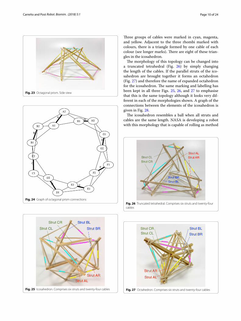
sizes of square duct. A graph of the connections in the octagonal prism is given in Fig. 24, which also provides labels of all elements.
IcosahedronThe expanded octahedron or icosahedron has six struts and twenty-four cables. All 6 struts can be organised in three groups: A, B, and C. Each group has of two parallel struts R and L (right and left). Therefore, all struts can be labelled AR, AL, BR, BL, CR, and CL as shown in Fig. 25. Cables can also be organised in six groups. Each group has four cables that resemble the shape of a rhombus.
Fig. 19 Square prism. Comprises four struts and twelve cables. Top view
Fig. 20 Square prism. Side view
Fig. 21 Graph of square prism connections
Fig. 22 Octagonal prism. Comprises eight struts and twenty-four cables. Top view
Page 10 of 24Carreño and Post Robot. Biomim. (2018) 5:1
Three groups of cables were marked in cyan, magenta, and yellow. Adjacent to the three rhombi marked with colours, there is a triangle formed by one cable of each colour (see longer marks). There are eight of these trian-gles in the icosahedron.
The morphology of this topology can be changed into a truncated tetrahedral (Fig. 26) by simply changing the length of the cables. If the parallel struts of the ico-sahedron are brought together it forms an octahedron (Fig. 27) and therefore the name of expanded octahedron for the icosahedron. The same marking and labelling has been kept in all three Figs. 25, 26, and 27 to emphasise that this is the same topology although it looks very dif-ferent in each of the morphologies shown. A graph of the connections between the elements of the icosahedron is given in Fig. 28.
The icosahedron resembles a ball when all struts and cables are the same length. NASA is developing a robot with this morphology that is capable of rolling as method
Fig. 23 Octagonal prism. Side view
Fig. 24 Graph of octagonal prism connections
Fig. 25 Icosahedron. Comprises six struts and twenty-four cables
Fig. 26 Truncated tetrahedral. Comprises six struts and twenty-four cables
Fig. 27 Octahedron. Comprises six struts and twenty-four cables
Page 11 of 24Carreño and Post Robot. Biomim. (2018) 5:1
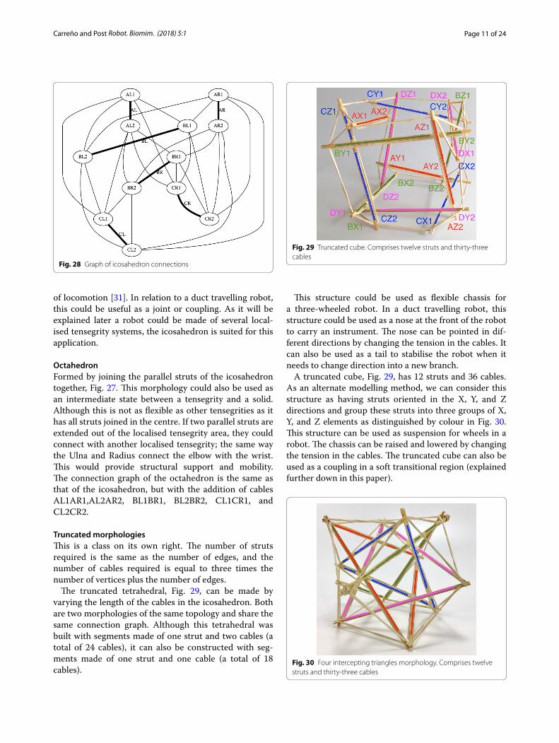
of locomotion [31]. In relation to a duct travelling robot, this could be useful as a joint or coupling. As it will be explained later a robot could be made of several local-ised tensegrity systems, the icosahedron is suited for this application.
OctahedronFormed by joining the parallel struts of the icosahedron together, Fig. 27. This morphology could also be used as an intermediate state between a tensegrity and a solid. Although this is not as flexible as other tensegrities as it has all struts joined in the centre. If two parallel struts are extended out of the localised tensegrity area, they could connect with another localised tensegrity; the same way the Ulna and Radius connect the elbow with the wrist. This would provide structural support and mobility. The connection graph of the octahedron is the same as that of the icosahedron, but with the addition of cables AL1AR1,AL2AR2, BL1BR1, BL2BR2, CL1CR1, and CL2CR2.
Truncated morphologiesThis is a class on its own right. The number of struts required is the same as the number of edges, and the number of cables required is equal to three times the number of vertices plus the number of edges.
The truncated tetrahedral, Fig. 29, can be made by varying the length of the cables in the icosahedron. Both are two morphologies of the same topology and share the same connection graph. Although this tetrahedral was built with segments made of one strut and two cables (a total of 24 cables), it can also be constructed with seg-ments made of one strut and one cable (a total of 18 cables).
This structure could be used as flexible chassis for a three-wheeled robot. In a duct travelling robot, this structure could be used as a nose at the front of the robot to carry an instrument. The nose can be pointed in dif-ferent directions by changing the tension in the cables. It can also be used as a tail to stabilise the robot when it needs to change direction into a new branch.
A truncated cube, Fig. 29, has 12 struts and 36 cables. As an alternate modelling method, we can consider this structure as having struts oriented in the X, Y, and Z directions and group these struts into three groups of X, Y, and Z elements as distinguished by colour in Fig. 30. This structure can be used as suspension for wheels in a robot. The chassis can be raised and lowered by changing the tension in the cables. The truncated cube can also be used as a coupling in a soft transitional region (explained further down in this paper).
Fig. 28 Graph of icosahedron connections
Fig. 29 Truncated cube. Comprises twelve struts and thirty-three cables
Fig. 30 Four intercepting triangles morphology. Comprises twelve struts and thirty-three cables
Page 12 of 24Carreño and Post Robot. Biomim. (2018) 5:1
When the ends of the struts on each side of the cube are joined closer together a different morphology com-prised of four intersecting triangles is made as shown in Fig. 30. Both Figs. 29 and 30 were colour marked to appreciate how the same struts have been displaced, and Fig. 31 shows a graph of connections.
Following the same pattern, a truncated dodecahedral, Fig. 32, can be built with 30 struts, 90 cables and having five-sided faces. This structure behaves essentially as a ball and is very complex to model and not of practical use for the purposes of the duct climbing robot in this paper.
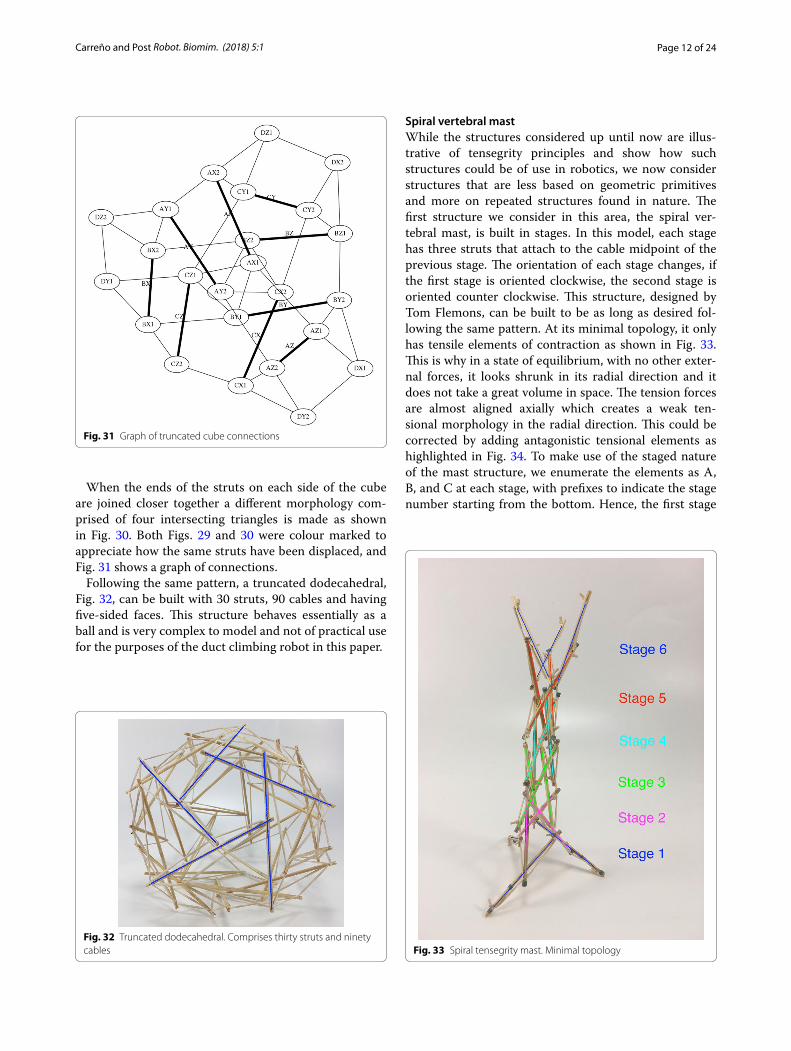
Spiral vertebral mastWhile the structures considered up until now are illus-trative of tensegrity principles and show how such structures could be of use in robotics, we now consider structures that are less based on geometric primitives and more on repeated structures found in nature. The first structure we consider in this area, the spiral ver-tebral mast, is built in stages. In this model, each stage has three struts that attach to the cable midpoint of the previous stage. The orientation of each stage changes, if the first stage is oriented clockwise, the second stage is oriented counter clockwise. This structure, designed by Tom Flemons, can be built to be as long as desired fol-lowing the same pattern. At its minimal topology, it only has tensile elements of contraction as shown in Fig. 33. This is why in a state of equilibrium, with no other exter-nal forces, it looks shrunk in its radial direction and it does not take a great volume in space. The tension forces are almost aligned axially which creates a weak ten-sional morphology in the radial direction. This could be corrected by adding antagonistic tensional elements as highlighted in Fig. 34. To make use of the staged nature of the mast structure, we enumerate the elements as A, B, and C at each stage, with prefixes to indicate the stage number starting from the bottom. Hence, the first stage
Fig. 31 Graph of truncated cube connections
Fig. 32 Truncated dodecahedral. Comprises thirty struts and ninety cables Fig. 33 Spiral tensegrity mast. Minimal topology
Page 13 of 24Carreño and Post Robot. Biomim. (2018) 5:1
is composed of struts 1A, 1B, and 1C, while the second stage is ordered in the opposite direction as 2A, 2B, and 2C to reflect the dual-spiral structure. The spiral ver-tebral mast can be collapsed along its axial direction as shown in Fig. 35 and will recover its original form when the external force applied is eliminated. The structure can be built with three or more struts in each state following the same pattern. Figure 36 shows a graph of the connec-tions for two complete stages of the structure connected to a third, with additional stages being added following the same pattern. Note that nodes 1A1, 1B1, and 1C1 are supporting the structure on the ground and nodes 3A1, 3B1, and 3C1 represent connection points to the next stage of the structure, hence the low number of cable connections.
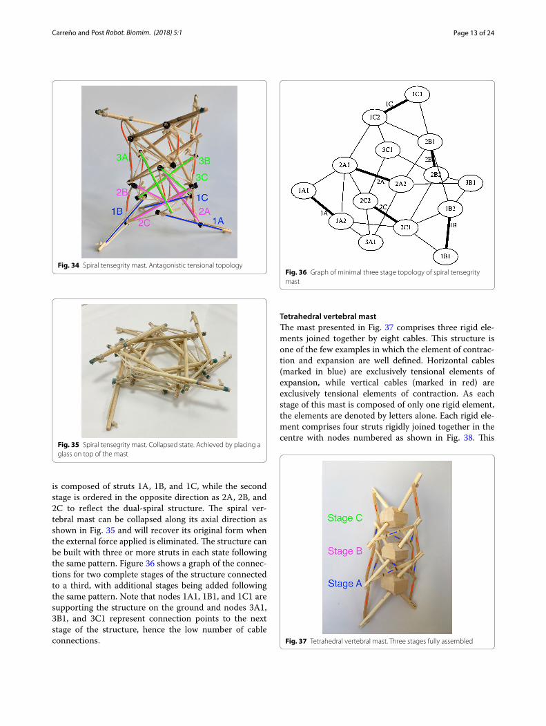
Tetrahedral vertebral mastThe mast presented in Fig. 37 comprises three rigid ele-ments joined together by eight cables. This structure is one of the few examples in which the element of contrac-tion and expansion are well defined. Horizontal cables (marked in blue) are exclusively tensional elements of expansion, while vertical cables (marked in red) are exclusively tensional elements of contraction. As each stage of this mast is composed of only one rigid element, the elements are denoted by letters alone. Each rigid ele-ment comprises four struts rigidly joined together in the centre with nodes numbered as shown in Fig. 38. This
Fig. 34 Spiral tensegrity mast. Antagonistic tensional topology
Fig. 35 Spiral tensegrity mast. Collapsed state. Achieved by placing a glass on top of the mast
Fig. 36 Graph of minimal three stage topology of spiral tensegrity mast
Fig. 37 Tetrahedral vertebral mast. Three stages fully assembled
Page 14 of 24Carreño and Post Robot. Biomim. (2018) 5:1
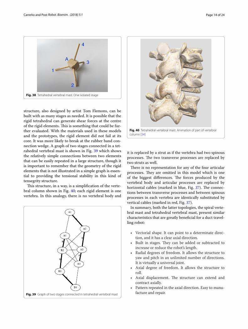
structure, also designed by artist Tom Flemons, can be built with as many stages as needed. It is possible that the rigid tetrahedral can generate shear forces at the centre of the rigid elements. This is something that could be fur-ther evaluated. With the materials used in these models and the prototypes, the rigid element did not fail at its core. It was more likely to break at the rubber band con-nection wedge. A graph of two stages connected in a tet-rahedral vertebral mast is shown in Fig. 39 which shows the relatively simple connections between two elements that can be easily repeated in a large structure, though it is important to remember that the geometry of the rigid elements that is not illustrated in a simple graph is essen-tial to providing the tensional stability in this kind of tensegrity structure.
This structure, in a way, is a simplification of the verte-bral column shown in Fig. 40; each rigid element is one vertebra. In this analogy, there is no vertebral body and
it is replaced by a strut as if the vertebra had two spinous processes. The two transverse processes are replaced by two struts as well.
There is no representation for any of the four articular processes. They are omitted in this model which is one of the biggest differences. The forces produced by the vertebral body and articular processes are replaced by horizontal cables (marked in blue, Fig. 37). The connec-tions between transverse processes and between spinous processes in each vertebra are identically substituted by vertical cables (marked in red, Fig. 37).
In summary, both the latter topologies, the spiral verte-bral mast and tetrahedral vertebral mast, present similar characteristics that are greatly beneficial for a duct travel-ling robot:
• Vectorial shape. It can point to a determinate direc-tion, and it has a clear axial direction.
• Built in stages. They can be added or subtracted to increase or reduce the robot’s length.
• Radial degrees of freedom. It allows the structure to yaw and pitch in an unlimited number of directions. It is virtually a universal joint.
• Axial degree of freedom. It allows the structure to roll.
• Axial displacement. The structure can extend and contract axially.
• Pattern repeated in the axial direction. Easy to manu-facture and repair.
Fig. 38 Tetrahedral vertebral mast. One isolated stage
Fig. 39 Graph of two stages connected in tetrahedral vertebral mast
Fig. 40 Tetrahedral vertebral mast. Animation of part of vertebral column [34]
Page 15 of 24Carreño and Post Robot. Biomim. (2018) 5:1
Transitional regionsThere are studies, like Motro [35], that address the prob-lem of joining together various tensegrity structures to form more complex and bigger ones. However, to the authors’ knowledge, there are no studies that address the problem of joining together a tensegrity structure with a fixed one. Therefore, in order to connect a tensegrity structure with a traditional mobile fixed structure, a new methodology will need to be developed. The following is a series of concepts that need to be formalised in the area of tensegrity and robotics.
Localised tensegrityTypical tensegrity structures have cables attached to struts at their endpoints. It should be noticed that this is common to see but not a requirement that defines a tensegrity system. This arrangement is so spread among the research community that limits the creativity in the development of new topologies.
When observing the musculoskeletal systems of ani-mals, it can be noticed that groups of muscles and ten-dons are localised into regions (i.e., shoulders, hips). Bones are the only elements to transcend those limits. It can be observed that the humerus extends beyond the shoulder and, similarly, the muscles in the shoulder area a located on one end of the humerus and do not extend up to the other end of it. In this case it can be considered that the rigid body acts as the transitional region between two localised tensegrity regions.
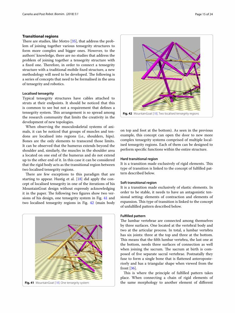
There are few exceptions to this paradigm that are starting to appear. Hustig et al. [18] did apply the con-cept of localised tensegrity in one of the iterations of his MountainGoat design without expressly acknowledging it in the paper. The following two figures show two ver-sions of his design, one tensegrity system in Fig. 41 and two localised tensegrity regions in Fig. 42 (main body
on top and foot at the bottom). As seen in the previous example, this concept can open the door to new more complex tensegrity systems comprised of multiple local-ised tensegrity regions. Each of them can be designed to perform specific functions within the entire structure.
Hard transitional regionIt is a transition made exclusively of rigid elements. This type of transition is linked to the concept of fulfilled pat-tern described below.
Soft transitional regionIt is a transition made exclusively of elastic elements. In order to be stable, it needs to have an antagonistic ten-sional setting: elements of contraction and elements of expansion. This type of transition is linked to the concept of unfulfilled pattern described below.
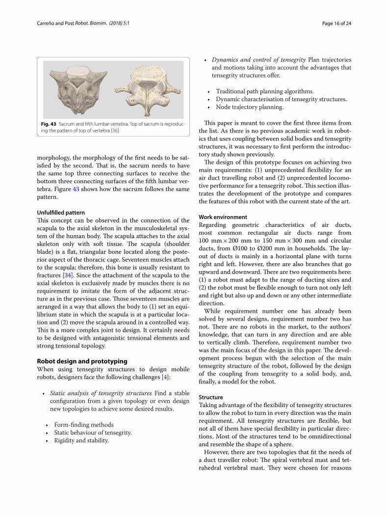
Fulfilled patternThe lumbar vertebrae are connected among themselves by three surfaces. One located at the vertebral body and two at the articular process. In total, a lumbar vertebra has six joints: three at the top and three at the bottom. This means that the fifth lumbar vertebra, the last one at the bottom, needs three surfaces of connection as well when joining the sacrum. The sacrum at birth is com-posed of five separate sacral vertebrae. Postnatally they fuse to form a single bone that is flattened anteroposte-riorly and has a triangular shape when viewed from the front [36].
This is where the principle of fulfilled pattern takes place. When connecting a chain of rigid elements of the same morphology to another element of different Fig. 41 MountainGoat [18]. One tensegrity system
Fig. 42 MountainGoat [18]. Two localised tensegrity regions
Page 16 of 24Carreño and Post Robot. Biomim. (2018) 5:1
morphology, the morphology of the first needs to be sat-isfied by the second. That is, the sacrum needs to have the same top three connecting surfaces to receive the bottom three connecting surfaces of the fifth lumbar ver-tebra. Figure 43 shows how the sacrum follows the same pattern.
Unfulfilled patternThis concept can be observed in the connection of the scapula to the axial skeleton in the musculoskeletal sys-tem of the human body. The scapula attaches to the axial skeleton only with soft tissue. The scapula (shoulder blade) is a flat, triangular bone located along the poste-rior aspect of the thoracic cage. Seventeen muscles attach to the scapula; therefore, this bone is usually resistant to fractures [34]. Since the attachment of the scapula to the axial skeleton is exclusively made by muscles there is no requirement to imitate the form of the adjacent struc-ture as in the previous case. Those seventeen muscles are arranged in a way that allows the body to (1) set an equi-librium state in which the scapula is at a particular loca-tion and (2) move the scapula around in a controlled way. This is a more complex joint to design. It certainly needs to be designed with antagonistic tensional elements and strong tensional topology.
Robot design and prototypingWhen using tensegrity structures to design mobile robots, designers face the following challenges [4]:
• Static analysis of tensegrity structures Find a stable configuration from a given topology or even design new topologies to achieve some desired results.
• Form-finding methods• Static behaviour of tensegrity.• Rigidity and stability.
• Dynamics and control of tensegrity Plan trajectories and motions taking into account the advantages that tensegrity structures offer.
• Traditional path planning algorithms.• Dynamic characterisation of tensegrity structures.• Node trajectory planning.
This paper is meant to cover the first three items from the list. As there is no previous academic work in robot-ics that uses coupling between solid bodies and tensegrity structures, it was necessary to first perform the introduc-tory study shown previously.
The design of this prototype focuses on achieving two main requirements: (1) unprecedented flexibility for an air duct travelling robot and (2) unprecedented locomo-tive performance for a tensegrity robot. This section illus-trates the development of the prototype and compares the features of this robot with the current state of the art.
Work environmentRegarding geometric characteristics of air ducts, most common rectangular air ducts range from 100 mm × 200 mm to 150 mm × 300 mm and circular ducts, from Ø100 to Ø200 mm in households. The lay-out of ducts is mainly in a horizontal plane with turns right and left. However, there are also branches that go upward and downward. There are two requirements here: (1) a robot must adapt to the range of ducting sizes and (2) the robot must be flexible enough to turn not only left and right but also up and down or any other intermediate direction.
While requirement number one has already been solved by several designs, requirement number two has not. There are no robots in the market, to the authors’ knowledge, that can turn in any direction and are able to vertically climb. Therefore, requirement number two was the main focus of the design in this paper. The devel-opment process begun with the selection of the main tensegrity structure of the robot, followed by the design of the coupling from tensegrity to a solid body, and, finally, a model for the robot.
StructureTaking advantage of the flexibility of tensegrity structures to allow the robot to turn in every direction was the main requirement. All tensegrity structures are flexible, but not all of them have special flexibility in particular direc-tions. Most of the structures tend to be omnidirectional and resemble the shape of a sphere.
However, there are two topologies that fit the needs of a duct traveller robot: The spiral vertebral mast and tet-rahedral vertebral mast. They were chosen for reasons
Fig. 43 Sacrum and fifth lumbar vertebra. Top of sacrum is reproduc-ing the pattern of top of vertebra [36]
Page 17 of 24Carreño and Post Robot. Biomim. (2018) 5:1
explained in “Transitional regions”. There was a slight modification to the original spiral mast: the structure constructed for the prototype was built with four struts on each stage for two reasons: (1) the robot will mainly turn up, down, right, and left, and (2) the robot fixed rigid body is a square bar. Therefore, four struts accom-modate the geometric requirements better.
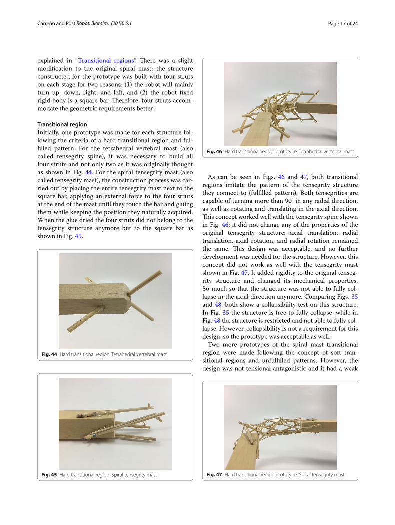
Transitional regionInitially, one prototype was made for each structure fol-lowing the criteria of a hard transitional region and ful-filled pattern. For the tetrahedral vertebral mast (also called tensegrity spine), it was necessary to build all four struts and not only two as it was originally thought as shown in Fig. 44. For the spiral tensegrity mast (also called tensegrity mast), the construction process was car-ried out by placing the entire tensegrity mast next to the square bar, applying an external force to the four struts at the end of the mast until they touch the bar and gluing them while keeping the position they naturally acquired. When the glue dried the four struts did not belong to the tensegrity structure anymore but to the square bar as shown in Fig. 45.
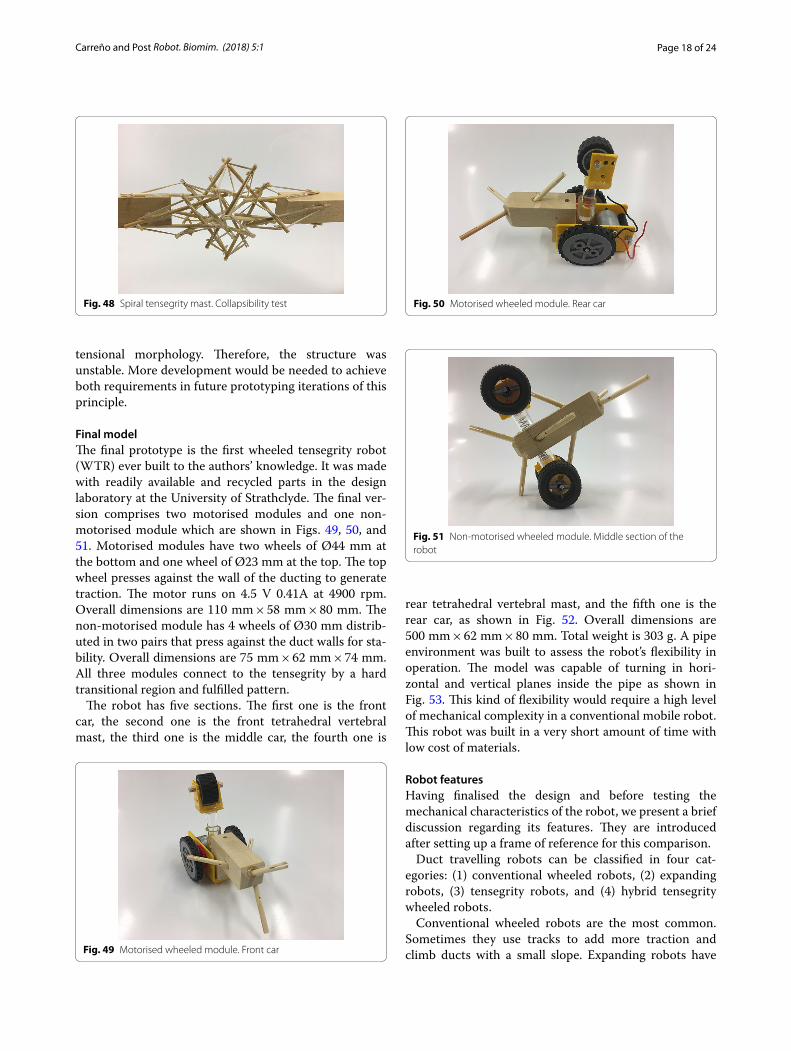
As can be seen in Figs. 46 and 47, both transitional regions imitate the pattern of the tensegrity structure they connect to (fulfilled pattern). Both tensegrities are capable of turning more than 90° in any radial direction, as well as rotating and translating in the axial direction. This concept worked well with the tensegrity spine shown in Fig. 46; it did not change any of the properties of the original tensegrity structure: axial translation, radial translation, axial rotation, and radial rotation remained the same. This design was acceptable, and no further development was needed for the structure. However, this concept did not work as well with the tensegrity mast shown in Fig. 47. It added rigidity to the original tenseg-rity structure and changed its mechanical properties. So much so that the structure was not able to fully col-lapse in the axial direction anymore. Comparing Figs. 35 and 48, both show a collapsibility test on this structure. In Fig. 35 the structure is free to fully collapse, while in Fig. 48 the structure is restricted and not able to fully col-lapse. However, collapsibility is not a requirement for this design, so the prototype was acceptable as well.
Two more prototypes of the spiral mast transitional region were made following the concept of soft tran-sitional regions and unfulfilled patterns. However, the design was not tensional antagonistic and it had a weak
Fig. 44 Hard transitional region. Tetrahedral vertebral mast
Fig. 45 Hard transitional region. Spiral tensegrity mast
Fig. 46 Hard transitional region prototype. Tetrahedral vertebral mast
Fig. 47 Hard transitional region prototype. Spiral tensegrity mast
Page 18 of 24Carreño and Post Robot. Biomim. (2018) 5:1
tensional morphology. Therefore, the structure was unstable. More development would be needed to achieve both requirements in future prototyping iterations of this principle.
Final modelThe final prototype is the first wheeled tensegrity robot (WTR) ever built to the authors’ knowledge. It was made with readily available and recycled parts in the design laboratory at the University of Strathclyde. The final ver-sion comprises two motorised modules and one non-motorised module which are shown in Figs. 49, 50, and 51. Motorised modules have two wheels of Ø44 mm at the bottom and one wheel of Ø23 mm at the top. The top wheel presses against the wall of the ducting to generate traction. The motor runs on 4.5 V 0.41A at 4900 rpm. Overall dimensions are 110 mm × 58 mm × 80 mm. The non-motorised module has 4 wheels of Ø30 mm distrib-uted in two pairs that press against the duct walls for sta-bility. Overall dimensions are 75 mm × 62 mm × 74 mm. All three modules connect to the tensegrity by a hard transitional region and fulfilled pattern.
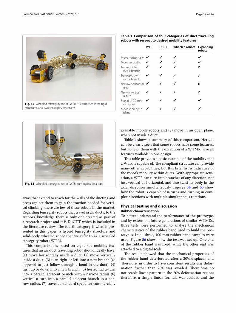
The robot has five sections. The first one is the front car, the second one is the front tetrahedral vertebral mast, the third one is the middle car, the fourth one is
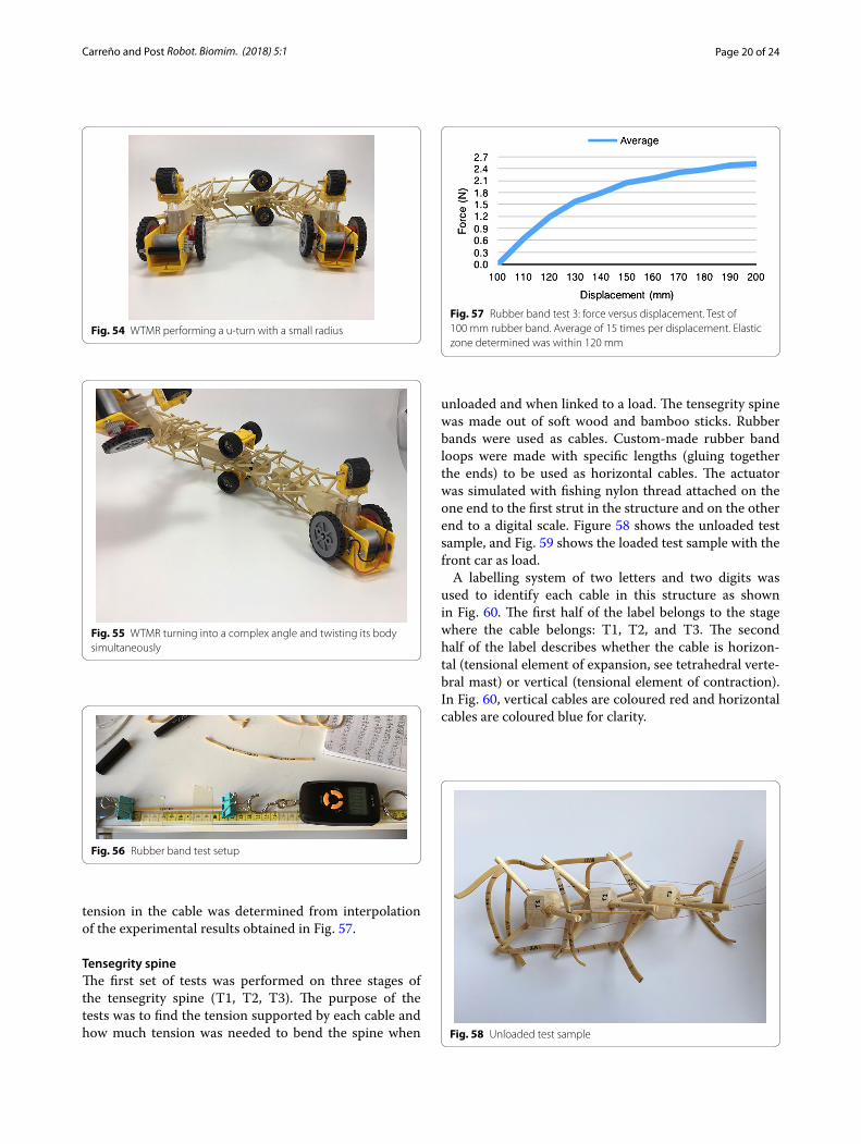
rear tetrahedral vertebral mast, and the fifth one is the rear car, as shown in Fig. 52. Overall dimensions are 500 mm × 62 mm × 80 mm. Total weight is 303 g. A pipe environment was built to assess the robot’s flexibility in operation. The model was capable of turning in hori-zontal and vertical planes inside the pipe as shown in Fig. 53. This kind of flexibility would require a high level of mechanical complexity in a conventional mobile robot. This robot was built in a very short amount of time with low cost of materials.
Robot featuresHaving finalised the design and before testing the mechanical characteristics of the robot, we present a brief discussion regarding its features. They are introduced after setting up a frame of reference for this comparison.
Duct travelling robots can be classified in four cat-egories: (1) conventional wheeled robots, (2) expanding robots, (3) tensegrity robots, and (4) hybrid tensegrity wheeled robots.
Conventional wheeled robots are the most common. Sometimes they use tracks to add more traction and climb ducts with a small slope. Expanding robots have
Fig. 48 Spiral tensegrity mast. Collapsibility test
Fig. 49 Motorised wheeled module. Front car
Fig. 50 Motorised wheeled module. Rear car
Fig. 51 Non-motorised wheeled module. Middle section of the robot
Page 19 of 24Carreño and Post Robot. Biomim. (2018) 5:1
arms that extend to reach for the walls of the ducting and press against them to gain the traction needed for verti-cal climbing; there are few of these robots in the market. Regarding tensegrity robots that travel in air ducts, to the authors’ knowledge there is only one created as part of a research project and it is DuCTT which is included in the literature review. The fourth category is what is pre-sented in this paper: a hybrid tensegrity structure and solid-body wheeled robot that we refer to as a wheeled tensegrity robot (WTR).
This comparison is based on eight key mobility fea-tures that an air duct travelling robot should ideally have: (1) move horizontally inside a duct, (2) move vertically inside a duct, (3) turn right or left into a new branch (as opposed to just follow through a bend in the duct), (4) turn up or down into a new branch, (5) horizontal u-turn into a parallel adjacent branch with a narrow radius (6) vertical u-turn into a parallel adjacent branch in a nar-row radius, (7) travel at standard speed for commercially
available mobile robots and (8) move in an open plane, when not inside a duct.
Table 1 shows a summary of this comparison. Here, it can be clearly seen that some robots have some features, but none of them with the exception of a WTMR have all features available in one design.
This table provides a basic example of the mobility that a WTR is capable of. The compliant structure can provide many other capabilities, but this brief list is indicative of the robot’s mobility within ducts. With appropriate actu-ation, a WTR can turn into branches of any direction, not just vertical or horizontal, and also twist its body in the axial direction simultaneously. Figures 54 and 55 show how the robot is capable of u-turns and turning in com-plex directions with multiple simultaneous rotations.
Physical testing and discussionRubber characterisationTo better understand the performance of the prototype, and by extension, future generations of similar WTMRs, three tests were performed to analyse the mechanical characteristics of the rubber band used to build the pro-totypes. In all three, 100 mm rubber band samples were used. Figure 56 shows how the test was set up. One end of the rubber band was fixed, while the other end was attached to a digital scale.
The results showed that the mechanical properties of the rubber band deteriorated after a 20% displacement. Therefore, in order to have consistent results any defor-mation further than 20% was avoided. There was no noticeable linear pattern in the 20% deformation region; therefore, a simple linear formula was avoided and the
Fig. 52 Wheeled tensegrity robot (WTR). It comprises three rigid structures and two tensegrity structures
Fig. 53 Wheeled tensegrity robot (WTR) turning inside a pipe
Table 1 Comparison of four categories of duct travelling robots with respect to desired mobility features
WTR DuCTT Wheeled robots Expanding robots
Move horizontally ✔ ✔ ✔ ✔Move vertically ✔ ✔ ✗ ✔Turn right/left
into a branch✔ ✔ ✔ ✗
Turn up/down into a branch
✔ ✔ ✗ ✗
Narrow horizontal u-turn
✔ ✗ ✔ ✗
Narrow vertical u-turn
✔ ✗ ✗ ✗
Speed of 0.7 m/s or higher
✔ ✗ ✔ ✔
Move in an open plane
✔ ✗ ✔ ✔
Page 20 of 24Carreño and Post Robot. Biomim. (2018) 5:1
tension in the cable was determined from interpolation of the experimental results obtained in Fig. 57.
Tensegrity spineThe first set of tests was performed on three stages of the tensegrity spine (T1, T2, T3). The purpose of the tests was to find the tension supported by each cable and how much tension was needed to bend the spine when
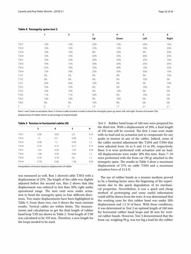
unloaded and when linked to a load. The tensegrity spine was made out of soft wood and bamboo sticks. Rubber bands were used as cables. Custom-made rubber band loops were made with specific lengths (gluing together the ends) to be used as horizontal cables. The actuator was simulated with fishing nylon thread attached on the one end to the first strut in the structure and on the other end to a digital scale. Figure 58 shows the unloaded test sample, and Fig. 59 shows the loaded test sample with the front car as load.
A labelling system of two letters and two digits was used to identify each cable in this structure as shown in Fig. 60. The first half of the label belongs to the stage where the cable belongs: T1, T2, and T3. The second half of the label describes whether the cable is horizon-tal (tensional element of expansion, see tetrahedral verte-bral mast) or vertical (tensional element of contraction). In Fig. 60, vertical cables are coloured red and horizontal cables are coloured blue for clarity.
Fig. 54 WTMR performing a u-turn with a small radius
Fig. 55 WTMR turning into a complex angle and twisting its body simultaneously
Fig. 56 Rubber band test setup
Fig. 57 Rubber band test 3: force versus displacement. Test of 100 mm rubber band. Average of 15 times per displacement. Elastic zone determined was within 120 mm
Fig. 58 Unloaded test sample
Page 21 of 24Carreño and Post Robot. Biomim. (2018) 5:1
The test consisted on measuring final length of 10 mm marks made on each cable. By measuring the displace-ment, the tension on the cables could be approximated. Tension in the actuator was measured with a digital scale.
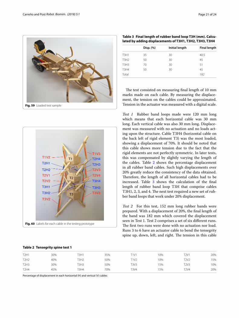
Test 1 Rubber band loops made were 120 mm long which means that each horizontal cable was 30 mm long. Each vertical cable was also 30 mm long. Displace-ment was measured with no actuation and no loads act-ing upon the structure. Cable T3H4 (horizontal cable on the back left of rigid element T3) was the most loaded, showing a displacement of 70%. It should be noted that this cable shows more tension due to the fact that the rigid elements are not perfectly symmetric. In later tests, this was compensated by slightly varying the length of the cables. Table 2 shows the percentage displacement in all rubber band cables. Such high displacements over 20% greatly reduce the consistency of the data obtained. Therefore, the length of all horizontal cables had to be increased. Table 3 shows the calculation of the final length of rubber band loop T3H that comprise cables T3H1, 2, 3, and 4. The next test required a new set of rub-ber band loops that work under 20% displacement.
Test 2 For this test, 152 mm long rubber bands were prepared. With a displacement of 20%, the final length of the band was 182 mm which covered the displacement seen in Test 1. Test 2 comprises a set of six different runs. The first two runs were done with no actuation nor load. Runs 3 to 6 have an actuator cable to bend the tensegrity spine up, down, left, and right. The tension in this cable
Fig. 59 Loaded test sample
Fig. 60 Labels for each cable in the testing prototype
Table 2 Tensegrity spine test 1
Percentage of displacement in each horizontal (H) and vertical (V) cables
T2H1 30% T3H1 35% T1V1 10% T2V1 20%
T2H2 40% T3H2 50% T1V2 10% T2V2 15%
T2H3 30% T3H3 50% T3V3 15% T2V3 10%
T2H4 45% T3H4 70% T3V4 15% T2V4 20%
Table 3 Final length of rubber band loop T3H (mm). Calcu-lated by adding displacements of T3H1, T3H2, T3H3, T3H4
Disp. (%) Initial length Final length
T3H1 35 30 40.5
T3H2 50 30 45
T3H3 70 30 51
T3H4 50 30 45
Total 182
Page 22 of 24Carreño and Post Robot. Biomim. (2018) 5:1
was measured as well. Run 1 showed cable T3H3 with a displacement of 25%. The length of the cable was slightly adjusted before the second run. Run 2 shows that this displacement was reduced to less than 20%; right under operational range. The next runs were under actua-tion to bend the tensegrity spine in four different direc-tions. Two major displacements have been highlighted in Table 4. From these two, run 4 shows the most extreme results. Vertical cables are within limits. The measure-ments and calculations to get the final length of rubber band loop T3H are shown in Table 2. Total length of T3H was calculated to be 193 mm. Therefore, a new length for the loops needed to be used.
Test 3 Rubber band loops of 160 mm were prepared for the third test. With a displacement of 20%, a final length of 192 mm will be covered. The first 2 runs were made with no load and no actuation just to compensate for any peaks in tension in any of the cables. Indeed, some of the cables needed adjustment like T2H4 and T3H4 that were adjusted from 16 to 6 and 13 to 8%, respectively. Runs 3–6 were performed with actuation and no load. All displacements were under 20% this time. Runs 7–10 were performed with the front car (94 g) attached to the tensegrity spine. The results in Table 5 show a maximum displacement of 27% on cable T3H4 and a maximum actuation force of 12.4 N.
The use of rubber bands as a tension medium proved to be a limiting factor since the beginning of the experi-ments due to the quick degradation of its mechani-cal properties. Nevertheless, it was a quick and cheap method of prototyping and some useful information could still be drawn from the tests. It was determined that the working zone for this rubber band was under 20% displacement and 1.2 N of force. With these conditions, it was determined in Test 2 an optimal length of 160 mm for horizontal rubber band loops and 30 mm for verti-cal rubber bands. However, Test 3 demonstrated that the front car, weighing 94 g, was too big a load for the rubber
Table 4 Tensegrity spine test 2
Runs 1 and 2 have no actuation. Runs 3–6 have a cable actuator in order to bend the tensegrity spine up, down, left, and right. Tension of actuator T(N)
Displacement of rubber shown as percentage of original length
1 2 3 4 5 6
Up Down Left Right
T2H1 10% 10% 20% 10% 20% 10%
T2H2 10% 10% 25% 15% 10% 20%
T2H3 10% 10% 8% 20% 0% 30%
T2H4 10% 10% 30% 30% 40% 20%
T3H1 10% 10% 30% 20% 25% 10%
T3H2 19% 15% 30% 20% 20% 30%
T3H3 25% 18% 20% 40% 10% 35%
T3H4 15% 18% 20% 30% 30% 10%
T1V1 5% 5% 0% 0% 0% 10%
T1V2 0% 0% 0% 0% 10% 0%
T2V1 20% 20% 10% 0% 0% 10%
T2V2 10% 10% 0% 0% 10% 0%
T2V3 10% 10% 0% 10% 0% 0%
T2V4 11% 11% 20% 0% 10% 5%
T3V3 10% 10% 0% 10% 0% 0%
T3V4 9% 9% 10% 0% 0% 0%
T 0 0 1.9 1.7 2.1 2.1
Table 5 Tension in horizontal cables (N)
Interpolation of tension based on displacement of rubber
3 4 5 6
T2H1 0.96 0.06 0.9 0.42
T2H2 1.2 0.3 0.48 1.2
T2H3 0.48 1.2 0.48 1.2
T2H4 0.78 0.72 0.72 0.72
T3H1 1.02 0.36 1.02 0.36
T3H2 1.08 0.54 0.66 1.2
T3H3 0.78 0.78 0.6 1.2
T3H4 0.78 0.96 1.08 0.66
Page 23 of 24Carreño and Post Robot. Biomim. (2018) 5:1
bands. Additionally, it was noticed that in the runs with the 94 g load the tensegrity rigid elements started touch-ing each other. This meant the tensegrity stopped behav-ing as such; cables in the tensegrity structure did not bear all loads anymore. The structure was overwhelmed by the load. Runs 3–6 in Test 3 can be used as an approximated method to calculate the loads on each cable based on the tension in the actuator, displacement, and Fig. 58.
ConclusionsWe have detailed how the very first wheeled tenseg-rity robot was successfully designed and prototyped. It was proven that this robot addressed all design require-ments for a duct traveller mobile robot. This novel design proved to have capabilities not found in just one robot. There are robot designs for vertical climbing, designs for facilitating turns to the right and left, and designs that focus on speed and efficiency of mobility, but none of them group all these requirements into a single structure like the wheeled tensegrity robot does.
This research furthers the knowledge in the ever-grow-ing field of tensegrity mobile robotics. It actually opens a new sub-category of hybrid wheeled tensegrity robot-ics. The project methodology was proven successful as it led to an optimised design that fulfilled all requirements. It had an advantage over simulation and analytical meth-ods in these particular circumstances. It certainly was best to approach the research by broadly study structures and build models to assess their properties. The criteria of evaluation were validated by prototyping. Accepted designs by the criteria were stable. Rejected designs by the criteria were unstable. Furthermore, these criteria need to be expanded. The author sees many more pos-sibilities of growth that were not pursued due to time constraints. Tensegrity robots do not need to address all design requirements with a tensegrity solution. Hybrid approaches have just been proved to be valid. Practi-cal applications should start to appear more in research work. Transition areas should not be constrained to mobile robotics. In civil engineering, they can be applied to add tensegrity structures to fixed structures.
Future work should include testing the locomotive effi-ciency of this design. The weight can be further lowered by reducing the number of cars from three to only two and adding a tail section at the end for stability. It could also include computer simulation to refine the topology and morphology created, building a prototype with metal springs and a metal body (possibly aluminium) and add-ing motorised actuators to control the structure. Flex-inol was also tested on this prototype as actuator, but the amount of actuation was much smaller that the structure required. However, a pulley arrangement is a possibility to be tested. Future work could also include exploring
other topologies applied to wheeled tensegrity robotics and continue developing the criteria and designs for soft transitional regions.
Authors’ contributionsFC performed the formal literature review, built the tensegrity structures, designed and constructed the wheeled tensegrity robot prototype, per-formed the laboratory evaluation of materials and mobility, and wrote the paper. MAP researched and presented the concept for a wheeled tensegrity robot, assembled the literature, supervised the work, and co-wrote the paper. All authors read and approved the final manuscript.
AcknowledgementsFor their support, we thank the DMEM lab technicians including Dino Bertol-accini, Duncan Lindsay, and Jim Mitchell. Many thanks also go to Tom Flemons for sharing the wisdom of many years building tensegrity structures.
Competing interestsThe authors declare that they have no competing interests.
FundingThis research was supported by internal funds from the Department of Design, Manufacture, and Engineering Management at the University of Strathclyde, and by provision by the Department of laboratory resources, materials for prototype construction, and expertise on the part of the labora-tory technicians in constructing the prototypes.
Publisher’s NoteSpringer Nature remains neutral with regard to jurisdictional claims in pub-lished maps and institutional affiliations.
Received: 27 December 2017 Accepted: 30 April 2018
References 1. Gough M. In the laboratory of constructivism: Karl Ioganson’s cold struc-
tures. October. 1998;84:91–117. https ://doi.org/10.2307/77921 0. 2. Snelson K. Letter from Kenneth Snelson to R. Motro. Int J Space Struct.
(1990) http://www.grunc h.net/snels on/rmoto .html. Accessed 19 July 2017.
3. Grimes W. Kenneth Snelson, sculptor who fused art, science and engineering, dies at 89. The New York Times (2016). https ://www.nytim es.com/2016/12/23/arts/desig n/kenne th-snels on-dead-sculp tor.html?smid=tw-nytob its&smtyp =cur. Accessed 25 July 2017.
4. Hernàndez S, Mirats J. Tensegrity frameworks: static analysis review. Mech Mach Theory. 2009;43(7):859–81.
5. Skelton RE, Adhikari R, Pinaud J-P, Chan WL, Helton JW. An introduc-tion to the mechanics of tensegrity structures. IEEE Conf Decis Control. 2001;5:4254–9.
6. Komendera E. A survey of the computational modeling and control of tensegrity robots. Ph.D. Prelim Exam in Computational Modeling Of Com-plex Systems, University of Colorado Department of Computer Science (2012).
7. Chen Y, Feng J, Wu Y. Novel form-finding of tensegrity structures using ant colony systems. J Mech Robot. 2012;4:1–7.
8. Rieffel J, Trimmer B, Lipson H. Mechanism as mind: what tensegrities and caterpillars can teach us about soft robotics. In: Artificial life XI: proceed-ings of the 11th international conference on the simulation and synthesis of living systems, ALIFE 2008, pp. 506–12 (2008).
9. Williamson D, Skelton RE. General class of tensegrity structures: topology and prestress equilibrium analysis. J Guid Control Dyn. 2003;26(5):685–94.
10. Motro R. Structural morphology of tensegrity systems. Asian J Civ Eng Build Hous. 2009;10(1):1–19.
Page 24 of 24Carreño and Post Robot. Biomim. (2018) 5:1
11. Rieffel J, Valero-Cuevas F, Lipson H. Automated discovery and opti-mization of large irregular tensegrity structures. Comput Struct. 2009;87:368–79.
12. Hernàndez S, Mirats J. A method to generate stable, collision free config-urations for tensegrity based robots. In: IEEE/RSJ international conference on intelligent robots and systems, pp. 3769–74 (2008).
13. Micheletti A, Williams WO. A marching procedure for form-finding for tensegrity structures. J Mech Mater Struct. 2007;2(5):857–82.
14. Levin S. The tensegrity-truss as a model for spine mechanics: biotenseg-rity. J Mech Med Biol. 2002;02(03&04):375–88.
15. Tietz BR, Carnahan RW, Bachmann RJ, Quinn RD, SunSpiral V. Tetraspine: robust terrain handling on a tensegrity robot using central patter genera-tors. In: 2013 IEEE/ASME international conference on advanced intelligent mechatronics (AIM) Wollongong, Australia, pp. 261–7 (2013).
16. Mirletz BT, Park I-W, Flemons TE, SunSpiral V. Design and control of modular spine-like tensegrity structures. In: 6th world conference of the international association or structural control and monitoring (2014).
17. Sabelhaus AP, Ji H, Hylton P, Madaan Y, Yang CW, Agogino AM, Friesen J, SunSpiral V. Mechanism design and simulation of the ULTRA spine: a tensegrity robot. In: Volume 5A: 39th mechanisms and robotics confer-ence (2015).
18. Hustig D, SunSpiral V, Teodorescu M. Morphological design for controlled tensegrity quadruped locomotion. IEEE/RSJ Int Conf Intell Robots Syst (IROS). 2016;2016:4714–9.
19. Scarr G. A consideration of the elbow as a tensegrity structure. Int J Osteopath Med. 2012;15(2):53–65.
20. Lessard S, Bruce J, Jung E, Tedorescu M, SunSpiral V, Agogino A. A lightweight, multi-axis compliant tensegrity joint. In: IEEE international conference on robotics and automation (ICRA), pp. 630–5 (2016).
21. Bliss T, Iwasaki T, Bart-Smith H. Central pattern generator control of a tensegrity swimmer. IEEE/ASME Trans Mechatron. 2013;18(2):586–97.
22. Motro R, Najari S, Jouanna P. Static and dynamic analysis of tensegrity systems. In: De Roeck G, Quiroga AS, Van Laethem M, Backx E, editors. Shell and spatial structures: computational aspects. Lecture notes in engineering, vol. 26. Berlin: Springer; 1987. p. 270–9.
23. Mirats-Tur JM, Hernàndez S, Rovira AG. Dynamic equations of motion for a 3-bar tensegrity based mobile robot. In: IEEE international conference on emerging technologies and factory automation, ETFA, pp. 1334–39 (2007).
24. Cefalo M, Mirats-Tur JM. A comprehensive dynamic model for class-1 tensegrity systems based on quaternions. Int J Solids Struct. 2011;48:785–802.
25. Skelton R, Oliveira M. Tensegrity systems. Berlin: Springer; 2009. 26. Friesen JM, Glick P, Fanton M, Manovi P, Xydes A, Bewley T, SunSpiral V.
The second generation prototype of a duct climbing tensegrity robot, DuCTTv2. In: IEEE international conference on robotics and automation (ICRA), pp. 2123–28 (2016).
27. Paul C, Roberts JW, Lipson H, Cuevas FC. Gait production in a tensegrity based robot. In: Advanced robotics, 2005. ICAR ‘05. Proceedings (2005).
28. Rovira AG, Mirats-Tur JM. Control and simulation of a tensegrity-based mobile robot. Robot Auton Syst. 2009;57(5):526–35.
29. Shibata M, Saijyo F, Hirai F. Crawling by body deformation of tensegrity structure robots. In: IEEE international conference on robotics and auto-mation, pp. 4375–80 (2009).
30. Bruce J, Sabelhous AP, Chen YX, Lu DZ, Morse K, Milam S, Caluwaerts K, Agogino AM, Sunspiral V, Cruz S. SUPERball: exploring tensegrities for planetary probes. In: 12th international symposium of artificial intel-ligence, robotics and automation in space (i-SAIRAS) (2014).
31. Sabelhaus AP, Bruce J, Caluwaerts K, Manovi P, Firoozi RF, Dobi S, Agogino AM, SunSpiral V. System design and locomotion of SUPERball, an unteth-ered tensegrity robot. In: 2015 IEEE international conference on robotics and automation (ICRA) (2015).
32. Friesen J, Pogue A, Bewley T, De Olieria M, Skelton R, Sunspiral V. DuCTT: a tensegrity robot for exploring duct systems. In: IEEE international confer-ence on robotics & automation (ICRA), pp. 4222–8 (2014).
33. SunSpiral V, Gorospe G, Bruce J, Iscen A, Korbel G, Milam S, Agogino A, Atkinson D. Tensegrity based probes for planetary exploration: entry, descent, and landing (EDL) and surface mobility analysis. Int J Planet Probes. 2013;7.
34. Complete Anatomy. Software App. Dublin: 3D4Medical Ltd; 2017. 35. Motro R. Tensegrity systems: the state of the art. J Space Struct.
1992;7(2):75–83. 36. Schuenke M, Schulte E, Schumacher U. Thieme atlas of anatomy: general
anatomy and musculoskeletal system. New York: Thieme; 2010.