Design of a Greywater-Fed Hydroponics System
113
Santa Clara University Santa Clara University Scholar Commons Scholar Commons Interdisciplinary Design Senior Theses Engineering Senior Theses Spring 2020 Design of a Greywater-Fed Hydroponics System Design of a Greywater-Fed Hydroponics System Alex Estrada Katya Fairchok Andrew Feldmeth Andrew Jezak Follow this and additional works at: https://scholarcommons.scu.edu/idp_senior Part of the Civil and Environmental Engineering Commons, and the Mechanical Engineering Commons
Transcript of Design of a Greywater-Fed Hydroponics System
Santa Clara University Santa Clara University
Scholar Commons Scholar Commons
Interdisciplinary Design Senior Theses Engineering Senior Theses
Spring 2020
Design of a Greywater-Fed Hydroponics System Design of a Greywater-Fed Hydroponics System
Alex Estrada
Katya Fairchok
Andrew Feldmeth
Andrew Jezak
Follow this and additional works at: https://scholarcommons.scu.edu/idp_senior
Part of the Civil and Environmental Engineering Commons, and the Mechanical Engineering Commons

SANTA CLARA UNIVERSITY
Department of Mechanical Engineering and Department of Civil, Environmental, and Sustainable Engineering Advisor
Date: June 12, 2020
I HEREBY RECOMMEND THAT THE THESIS PREPARED UNDER MY SUPERVISION BY
Alex Estrada, Katya Fairchok, Andrew Feldmeth, Andrew Jezak
ENTITLED
DESIGN OF A GREYWATER-FED HYDROPONICS SYSTEM
BE ACCEPTED IN PARTIAL FULFILLMENT OF THE REQUIREMENTS FOR THE DEGREE OF
BACHELOR OF SCIENCE IN
MECHANICAL ENGINEERING CIVIL, ENVIRONMENTAL, AND SUSTAINABLE ENGINEERING
Dr. Laura Doyle, Civil, Environmental, and Sustainable Engineering Advisor date
Dr. Hohyun Lee, Mechanical Engineering Advisor date
Dr. Drazen Fabris, Mechanical Engineering Department Chair date
Dr. Ed Maurer, Civil, Environmental, and Sustainable Engineering Department Chair date

Design of a Greywater-Fed Hydroponics System
By Alex Estrada
Katya Fairchok Andrew Feldmeth
Andrew Jezak
SENIOR THESIS
Submitted to
the Department of Mechanical Engineering
and the Department of Civil, Environmental, and sustainable Engineering
of
SANTA CLARA UNIVERSITY
in partial fulfillment of the requirements for the degrees of
Bachelor of Science in Mechanical Engineering Bachelor of Science in Civil Engineering
Santa Clara, California
Spring 2020

iii
Abstract
To combat issues of local water insecurity, a hydroponics system was designed in
partnership with LEAP 5 High School in Jane Furse, South Africa. Climate change, increasing
human population, and continued environmental degradation all threaten access to clean drinking
water. Approximately seventy percent of all freshwater is used for agriculture globally, thus
threatening food security especially in developing countries where access to water is potentially
volatile. The hydroponics garden system utilizes sustainable materials, a self-monitoring
temperature controls system, and greywater input, to act as an educational tool for students and
significantly reduce freshwater use compared to traditional, in-ground agriculture. An education
plan accompanies the implementation of the system to provide an avenue for community
engagement and encourage the adoption of alternative, water-saving farming methods. The
hydroponics system was developed by observing the strengths of existing hydroponics
applications in commercial and educational institutions. The successes of established systems
guided rapid prototyping of grow beds, shading structure, and greywater filter. The fully built
system reflected all major subsystems and was used to test the effectiveness of a hydroponics
garden compared to a traditional soil garden, and the growth of lettuce plants confirmed the
benefits of hydroponics. The hydroponics method of farming was found to produce triple the
lettuce per the same volume of water when compared with soil faring. Additionally, 30% less
energy was required to operate the hydroponics system and the cost of materials was decreased
50% compared to past student projects and existing systems commercially available systems.
The greywater-fed hydroponics system proves that an inexpensive, durable design displays
significant advantages over standard, soil farming. Educational assembly manuals and tailored
education modules designed for the LEAP 5 High School will aid in the adoption of a potentially
disruptive farming method to an agriculturally dependent region.

iv
Acknowledgements
We want to thank Santa Clara University School of Engineering, Xilinx, and family
members and friends for their donations to this project. We thank our advisors Dr. Laura Doyle,
Dr. Hohyun Lee for their support for this project. We are also grateful for the help of Allan Baez
Morales, The Frugal Innovation Hub, Dr. Michele Parker, Brent Woodcock, Katharine
Rondthaler, Dr. Aria Amirbahman, Jessica Kuczenski, and Sam Bertram provided us. Finally, we
are grateful to our partner and client LEAP 5 Science and Math Schools of South Africa,
especially Principal Raphael Mukachi for his continual dedication and aid throughout the year.

v
Table of Contents
Abstract ....................................................................................................................................................................... iii
Acknowledgements .................................................................................................................................................. iv
Table of Contents ...................................................................................................................................................... v
List of Figures ........................................................................................................................................................... ix
List of Tables ............................................................................................................................................................. xi
Nomenclature ........................................................................................................................................................... xii
1.Introduction ............................................................................................................................................................. 1
1.1 Water Scarcity ................................................................................................................................................. 1
1.2 LEAP 5 School of Science and Maths ....................................................................................................... 3
1.3 Project Background ........................................................................................................................................ 4
1.3.1 Educational Opportunities in Hydroponics ...................................................................................... 5
1.3.2 Approaches to Constructing a Hydroponics System ...................................................................... 6
1.3.3 Advantages of Greywater-fed Hydroponics Systems .................................................................. 10
2. Design Specifications ......................................................................................................................................... 10
2.1 Customer Needs ............................................................................................................................................ 11
2.2 Functional Analysis Decomposition ........................................................................................................ 12
2.3 Existing System Benchmarking ................................................................................................................ 13
2.4 Rationale for System Specifications ........................................................................................................ 14
2.5 System Configuration .................................................................................................................................. 17
2.6 Project Management .................................................................................................................................... 19
2.6.1 Design Challenges and Goals ............................................................................................................ 19
2.6.2 Budget Consideration .......................................................................................................................... 20
2.6.2.1 Expenses ......................................................................................................................................... 21

vi
2.6.2.2 Income ............................................................................................................................................. 21
2.6.3 Timeline .................................................................................................................................................. 22
2.6.4 Risks and Mitigations .......................................................................................................................... 23
2.6.4.1 Risks ................................................................................................................................................. 24
2.6.4.2 Mitigations ...................................................................................................................................... 24
2.6.5 Team Management ............................................................................................................................... 25
3. Subsystems ........................................................................................................................................................... 26
3.1 Grow Beds ...................................................................................................................................................... 27
3.1.1 Raft Bed .................................................................................................................................................. 27
3.1.2 Wicking Bed .......................................................................................................................................... 30
3.2 Shading Structure .......................................................................................................................................... 32
3.2.1 Design Considerations ......................................................................................................................... 32
3.2.1.1 Design 1: Hand Fan Design ........................................................................................................ 33
3.2.1.2 Design 2: Reinforced Hand Fan Design .................................................................................. 33
3.2.1.3 Design 3: Square Frame Design ................................................................................................ 33
3.2.2 Finalized Detailed Design .................................................................................................................. 34
3.2.3 Manual Consideration ......................................................................................................................... 36
3.2.4 Automatic Consideration .................................................................................................................... 37
3.2.5 Analysis of the Shading Structure .................................................................................................... 37
3.2.5.1 Stress Analysis ............................................................................................................................... 38
3.2.5.2 Thermal Analysis .......................................................................................................................... 42
3.3 Plumbing ......................................................................................................................................................... 45
3.3.1 Pump Selection...................................................................................................................................... 45
3.4 Greywater Filter ............................................................................................................................................ 48
3.4.1 Greywater Filter Design Alternatives Analysis ............................................................................. 48
3.4.1.1 Alternative 1: EcoSense Worm Filter ...................................................................................... 48
3.4.1.2 Alternative 2: Bioretention Filter .............................................................................................. 49
3.4.1.3 Alternative 3: Mulched Surge Tank with Constructed Wetland ........................................ 50
3.4.1.4 Selection of Best Alternative ..................................................................................................... 51
3.4.2 Greywater Filter Final Design ........................................................................................................... 52

vii
3.5 Controls and Data Logging ........................................................................................................................ 53
4. Results .................................................................................................................................................................... 54
4.1 Filtered Greywater Quality ......................................................................................................................... 56
5. Sustainability Analysis....................................................................................................................................... 58
5.1 Water Savings ................................................................................................................................................ 58
5.2 Energy Savings .............................................................................................................................................. 58
5.2.1 Assumptions Related to the Use of Our Project and the Scope of Influence. ........................ 59
5.2.2 Materials Environmental Analysis ................................................................................................... 59
6. Business Plan ....................................................................................................................................................... 61
6.1 Business Plan Executive Summary .......................................................................................................... 61
6.2 Perceived Markets ........................................................................................................................................ 61
6.3 Business Objectives ..................................................................................................................................... 62
6.4 Manufacturing ............................................................................................................................................... 63
6.4.1 Assembly Manuals ............................................................................................................................... 64
6.5 System Pricing ............................................................................................................................................... 65
6.6 Financial Plan (ROI) .................................................................................................................................... 67
6.7 Marketing ....................................................................................................................................................... 68
7. Ethical Analysis ................................................................................................................................................... 68
8. Future Considerations ........................................................................................................................................ 70
9. Conclusion ............................................................................................................................................................ 71
References ................................................................................................................................................................. 73
Appendices ................................................................................................................................................................ 76
Appendix A: Shading Structure Design Options ......................................................................................... 76
Appendix B: Shading Structure Hand and FEA Calculations .................................................................. 79

viii
Appendix C: Pump Selection Calculations ................................................................................................... 86
Appendix D: Temperature Data Logging Materials ................................................................................... 87
Appendix E: Location Photos of LEAP 5 High School ............................................................................. 89
Appendix F: Greywater Filter Hand Calculations and Design ................................................................. 95

ix
List of Figures Figure 1: Map of the projected water scarcity globally by 2025 . ...................................................................... 2
Figure 2: Map of South Africa ............................................................................................................................ 3
Figure 3: Sample lecture slides from the hydroponics curriculum. .................................................................... 5
Figure 4: Schematic depicting basic DWC configuration . ................................................................................ 8
Figure 5: Side by side comparison of the similar drip and ebb & flow systems. ............................................... 9
Figure 6: South Africa hydroponic system layout for LEAP 5. ....................................................................... 19
Figure 7: Overview of project schedule timeline. ............................................................................................. 23
Figure 8: Model of raft bed frame..................................................................................................................... 28
Figure 9: Finite Element Strength Analysis of raft bed frame with simulated water loading .......................... 29
Figure 10: Model depicting the bathtub used to house the soil and the frame. ................................................ 30
Figure 11: Cross section of wicking bed plumbing and layers. ........................................................................ 31
Figure 12: Shading Structure Subsystem. ......................................................................................................... 35
Figure 13: Shading Structure retracted and deployed. ...................................................................................... 36
Figure 14: Rope interwoven between shading material grommets. .................................................................. 37
Figure 15: Stress analysis was conducted on this selected ABS pipe............................................................... 39
Figure 16: FEA of top ABS section where bearing bracket fastens. ................................................................ 41
Figure 17: Non-linear relationship between shading percentage and temperature. .......................................... 44
Figure 18: Pump curves for each of the Active Aqua submersible pumps ideal for hydroponics, with both
systems flow requirements ................................................................................................................................ 46
Figure 19: Pump cost comparison for different pump system setups. .............................................................. 47
Figure 20: The EcoSense Worm Biofilter ........................................................................................................ 49
Figure 21: Displays the sink to the filtered path of the proposed bioretention filter for LEAP 5 .................... 50
Figure 22: Displays the functions of a constructed wetland. ............................................................................ 51
Figure 23: Greywater filter orientation at LEAP 5. .......................................................................................... 53
Figure 24: 50-day growth of butterhead and tri-color romaine lettuce ............................................................. 55
Figure 25: Significant tomato growth in the wicking bed and leafy greens in raft bed .................................... 56
Figure 26: Measured water quality difference between kitchen sink greywater and after it has passed through
the Mulch Retention Filter compared to optimal vegetable growing parameters. ............................................ 57
Figure 27: Graphical representation of the energy use of the South African system compared to the energy
use of a Commercial Setup, retrofitted to produce the same grow space as the project system over the course
of a 1- year use time .......................................................................................................................................... 60

x
Figure 28: Construction sequencing of the raft bed frame included in the manual to be sent to: Construction
sequencing of the raft bed frame included in the manual to be sent to students and teachers at LEAP 5. ....... 64
Figure 29: Construction sequencing of the shading structure included in the manual to be sent to students and
teachers at LEAP 5............................................................................................................................................ 65
Figure 30: The total capital costs broken down per each subsystem. ............................................................... 66
Figure A1: Hand Fan Shading Design .............................................................................................................. 76
Figure A2: Reinforced Hand Fan Design ......................................................................................................... 77
Figure A3: Square Frame Design ..................................................................................................................... 78
Figure B1: Horizontal tubing with equally distributed weight and resultant forces from each bracket. .......... 79
Figure B2: Shear forces observed in bolts on ABS piping. .............................................................................. 80
Figure B3: Diagram depicting solar load experienced by grow bed and shading structure. ............................ 81
Figure B4: Hand calculations for maximum stress in ABS given load of motor and tubing assembly. .......... 82
Figure B5: Calculations to determine the maximum vertical force capable of being withstood by the solar
shade until critical bearing failure occurs in ABS. ........................................................................................... 83
Figure B6: Calculation for surface temperature of grow beds given 50% shading at 68.7 °F ......................... 84
Figure B7: Styrofoam grow bed surface temperature test ................................................................................ 85
Figure C1: Pump Head Loss Calculation Spreadsheet. .................................................................................... 86
Figure D1: Arduino code for Node MCU wifi chip. ........................................................................................ 87
Figure D2: Template of excel spreadsheet for weekly temperature histogram reports. ................................... 88
Figure D3: QR code to access the temperature reading app. ............................................................................ 88
Figure E1: Existing Conditions Photos at LEAP 5 High School in Jane Furse, South Africa. ........................ 89
Figure E2: Bathtubs that will be reused for wicking grow beds. ...................................................................... 90
Figure E3: Scrap metal yard with material at hydroponic team’s disposal. ..................................................... 91
Figure E4: Hydroponic system planned implementation location. ................................................................... 92
Figure E5: LEAP 5 greywater catchment system. ............................................................................................ 93
Figure E6: Location of overflow basin that waters lawn. ................................................................................. 94
Figure F1: Hand Calculations for Sizing of Greywater Filter. ......................................................................... 95
Figure F2: Preliminary Design of Constructed Wetland Greywater Filter. ...................................................... 96
Figure F3: Hand Sketch of Biofilter Design for Greywater Filtration. ............................................................. 97
Figure F4: Sedimentation tank hand drawing reference for design. ................................................................. 98
Figure F5: Biofilter layers shown as a cross-sectional view. ............................................................................ 99
Figure F6: Hand sketch of filtered water reservoir. ........................................................................................ 100

xi
List of Tables
Table 1: Summaries of unique characteristics relative to each considered type of grow bed…….6
Table 2: List of consulted clients and their most critical needs listed…………………………....12
Table 3: Summary of Current Hydroponic Systems on the Market……………………………...13
Table 4: Customer needs………………………………………………………………………....14
Table 5: Metrics table with units………………………………………………………………....16
Table 6: Benchmarking metrics for project’s hydroponic system……………………………….17
Table 7: Design goals for each contributing engineering major…………………………………20
Table 8: Cost of materials used to prototype the system in Forge Garden, Santa Clara…………21
Table 9: Fundraising sources/amounts…………………………………………………………..22
Table 10: Timeline of key tasks………………………………………………………………....23
Table 11: Detail of hazards encountered during manufacturing process……………………..…24
Table 12: Detail of preventative actions to remedy hazards…………………………….....…....25
Table 13: Concept selection matrix for shading system……………………………………..….34
Table 14: Percent solar shade porosity tested compared to the grow bed surface temperature…43
Table 15: Volume and volumetric flow rate requirements and corresponding head loss for each
system.…………………………………………………………………………………………..46
Table 16: Performance of filters based on established criteria…………………………………52
Table 17: Water savings and annual yield comparison between the hydroponics design and a soil
garden baseline with the same growth area…………………………………………………….58
Table 18: Cost-benefit comparisons between the LEAP 5 hydroponics design and raised bed soil
farming with the same grow area……………………………………………………………….67
xii
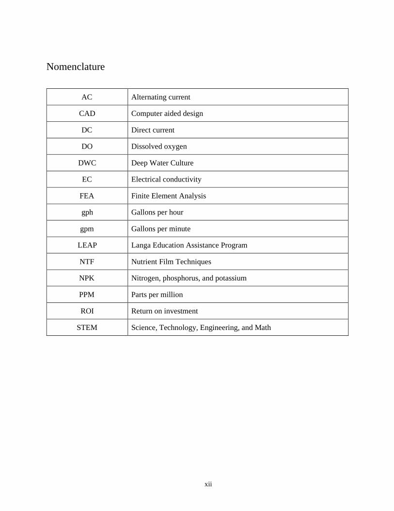
Nomenclature
AC Alternating current
CAD Computer aided design
DC Direct current
DO Dissolved oxygen
DWC Deep Water Culture
EC Electrical conductivity
FEA Finite Element Analysis
gph Gallons per hour
gpm Gallons per minute
LEAP Langa Education Assistance Program
NTF Nutrient Film Techniques
NPK Nitrogen, phosphorus, and potassium
PPM Parts per million
ROI Return on investment
STEM Science, Technology, Engineering, and Math

1
1. Introduction
The effects of climate change and environmental degradation are threatening the world’s
access to its most precious natural resource, freshwater. With a growing human population, it is
essential to grow more food with less water.
Our project is made in partnership with Langa Education Assistance Program 5 (LEAP 5)
high school, a STEM school that caters to economically disadvantaged students located in the
Limpopo Province, South Africa. The implementation of a more water efficient farming method
as an educational tool for students was the main project objective. In collaboration with students
and faculty, a greywater-fed hydroponics garden was designed for the LEAP 5 campus.
Compared to traditional agriculture methods, our system puts more emphasis on
sustainability and water conservation by using sustainable materials and recycling greywater
produced by the LEAP 5 school kitchen. In doing so, the system becomes a benefit not just for
the school, but for the entire Jane Furse community. The system was built to reduce the
environmental impact of growing plants which are associated with traditional farming methods.
To further increase the water efficiency in the system, a kitchen sink greywater filter will supply
the hydroponics garden instead of using freshwater. A successful hydroponics system can
provide both water and food security to agricultural communities in South Africa.
1.1 Water Scarcity
Globally, 70% of all freshwater is used for agriculture [1]. Estimates from the World
Bank predict that, by 2050, “feeding a planet of 9 billion people will require an estimated 50
percent increase in agricultural production and 15 percent increase in water withdrawals” [1].

2
Figure 1: Map of the projected water scarcity globally by 2025 [3].
The overuse of freshwater in agriculture can create food and water insecurity, especially
in developing countries. In sub-saharan Africa, 80.7% of all available fresh water is utilized for
agriculture [1]. This is also the only world region unable to meet the minimum standards for
sustainable safe drinking water, according to the United Nations’ Millennium Development
Goals [2].
South Africa is the wealthiest nation in sub-saharan Africa and has granted citizens the
right to clean water access, yet over one million households suffer from water insecurity [4, 5].
The increasing frequency and severity of droughts, due to climate change, coupled with the
diversion of freshwater to urban areas has significantly reduced the amount of available water to
rural, agricultural communities [6, 7]. Water scarcity in the Limpopo Province, where our project
is located, has forced communities to utilize natural sources of water that are often contaminated
or polluted [7]. Figure 2 shows the map of the country of South Africa.

3
Figure 2: Map of South Africa with the Limpopo Province highlighted in red and LEAP 5 High
School represented with a star [8].
Implementation of this more efficient farming method addresses water scarcity in South
Africa, while still yielding adequate crops for consumption and profit. Hydroponics systems, or
soilless farming, use more than 75% less water per kilogram of produce compared to traditional
in-ground agriculture and increase the amount of produce grown per square meter described in
Section 5.1 [7]. Fifty percent faster harvest times, freedom from pesticide use, the adaptability of
the system to space constraints, and the opportunity to grow year round also make hydroponic
systems a viable alternative for traditional in-ground farming.
1.2 LEAP 5 School of Science and Maths
An education plan was developed to accompany the implementation of the system that
would provide an avenue for community engagement and encourage adoption of alternative,
water saving farming methods in the wider community. With help from the Frugal Innovation
Hub on campus, our team was partnered with LEAP 5 Science and Math Schools in South
Africa. LEAP is a collection of math and science focused schools that caters to economically
disadvantaged students across the country.

4
The fifth LEAP school reached out to the Frugal Innovation Hub in hopes of recruiting a
team like us for their project. A couple of the project team members were interested in designing
an aquaponics system and heard about this opportunity with the Frugal Innovation Hub in the
Civil Engineering Senior Design Class in Spring 2019. The first contact our team made with
LEAP 5 shortly followed. Raphael, the school’s principal, and a handful of eager students came
to us with an idea for an alternative solution to traditional farming. The students led the
discussion with their eagerness to learn and grow peppers and carrots. Weekly progress meetings
were organized for three months and featured constant messaging and communication. This was
the motivating factor throughout our whole project, the high school students enthusiasm for us to
come and teach them. Their three main priorities for a successful project were:
1. Agricultural & Water Conservation Education - this included hands on education and
curriculum-based recommendations in the field of Engineering Design, Biology, and
Business.
2. Fresh Produce Yield and Food Security - used for both the students and faculty at LEAP
5 and in the surrounding communities’ food banks.
3. Replicable Across LEAP School System - LEAP 5 wished to be a catalyst for agricultural
education across the South Africa school system
Our role in the project would be to create a physical learning module which both informs
about water conservative farming methods, promotes food security, and shows that engineering
can be applicable to these students' lives.
1.3 Project Background
Alongside the teachers and students from LEAP 5 High School, a greywater-fed
hydroponics garden was designed and tested in Santa Clara with the intention of implementing
the complete system in South Africa during Spring 2020. To address alternative agriculture,
hydroponics is a method that supports plants’ roots in nutrient rich water instead of traditional
soil farming. To further address freshwater insecurity, the system would employ LEAP’s kitchen

5
sink wastewater (greywater) to supply the garden when water levels drop due to evaporation and
evapotranspiration.
1.3.1 Educational Opportunities in Hydroponics
Implementing alternative farming systems requires community engagement and
ownership to ensure the success and longevity of the technology. One of the central focuses of
this project was STEM education and student involvement. Thus, 15 hours of lectures, activities,
and experiments were designed to connect the fields of Biology, Biochemistry, Environmental
Science, and Engineering to the on-site construction of the hydroponics system. The educational
materials were developed to be implemented over a 5 day period (3 hours instruction/day) with
20 student ambassadors at LEAP 5.
The education piece had three main learning objectives: 1) to understand how climate
change will impact both humans and plant survival, 2) to understand how the hydroponics
system functions and be able to maintain it, 3) to empower students to make a positive impact in
their own local communities. Lessons on plant biology and photosynthesis, biochemistry,
ecosystem ecology, and climate science connected to different aspects of the hydroponics
system. Plant biology, in particular, was a central focus of the education materials shown in
Figure 3.
Figure 3: Sample lecture slides from the hydroponics curriculum.
Each lesson plan included two lab experiments or hands-on activities to practice newly
learned skills and daily interaction with the hydroponics system to achieve the first two learning
objectives. To address the third learning objective, the lesson plans included examples of
student-led movements for climate change, such as speeches by Greta Thunberg, to inspire and

6
empower students to address climate change in their school and larger local community. The
educational materials allow for the learning and application of new science and engineering
concepts, while providing an opportunity for students to improve local agricultural systems.
1.3.2 Approaches to Constructing a Hydroponics System
When starting a hydroponics farm, a specific type or multiple types of hydroponics
systems must be selected. The most prominent types of systems are: Nutrient film techniques
(NFT), Deep water culture (DWC), Drip irrigation systems, ebb & flow, and wicking. There are
other techniques, but this document will not include a discussion of them because they were
deemed unsuitable for our desired product. Table 1 lists styles of hydroponic farming
configurations and their major aspects.
Table 1: Summaries of unique characteristics relative to each considered type of grow bed. Blue
highlighted rows were the systems chosen for the final design.
Type of Grow
Bed
Significant Characteristics
Raft Bed (Deep
Water Culture)
● Plants housed in holes on styrofoam rafts which float in a
large reservoir of nutrient-rich water.
● Requires sturdy construction of frame due to water weight.
Nutrient-Film
Technique
● Plants housed in holes bored into long rails or large
diameter pipes.
● Single stream of nutrient-rich water feeds all plants in series.
Drip Line
Irrigation
● Nutrient-rich water is delivered periodically to plants in a
media through a pressurized flexible rubber drip line.
● Each plant requires at least one thin rubber line resulting in
large networks if the garden is large.
Ebb & Flow
● Plants rest in a media bed and water is delivered to flood the
entire volume of the grow bed -- upon reaching a designated
height, water is removed by a bell siphon. The process repeats.
● If the system is large the fluctuation of each fill-drain cycle is
a significant volume of water
Wicking Bed ● Nutrient rich water is delivered by a buried, perforated pipe.
● A shallow reservoir is maintained below the topsoil and the water is
then “wicked” towards the plants’ roots via capillary action.

7
Nutrient film techniques utilize a simple design consisting of a main reservoir and an
angled grow tray which plants are fitted into. Water rich in minerals and nutrients enters from the
uphill end of the grow tray as it is pumped from the reservoir. The water then flows down the
tray, passing by each individual plant and soaking the root system before departing through the
downhill tray side and returning to the reservoir [7]. Advantages to NFT are that it uses a
continuous flow so no pump timing equipment is necessary. There are few moving parts to an
NFT system and they can be customized and scaled with ease. The depth of water that flows
through the grow tray is very shallow to compensate for the continual flow. The plants are able
to wick water from the stream and draw as much as required. Different plants have different
water needs so this presents a viable system if a diverse garden is desired. The NFT is not
without disadvantages though. These systems are extremely sensitive to power outages and if a
loss of flow due to no power or a clog in the input line occurs, the plants will wilt and die
rapidly. Another negative for this system is the depletion of nutrients as the stream approaches
the return to the reservoir. Plants all need nutrients and will draw from the finite supply as soon
as they encounter the water. The plants growing at the downhill end of the grow tray do not
encounter a stream of water as rich in nutrients and suffer slightly.
Deep water culture systems are extremely simple and are very relevant in the world of
commercial farming. DWC is most effective for quick-growing, leafy greens which have
significant water needs. The setup for a DWC is extremely simple and requires almost no
moving parts and most importantly no water pump to circulate the water[9]. The DWC method
only requires that the water be aerated so that enough oxygen is present for the roots to grow.
Aeration is obtained by an air pump and airstone in most cases, both of which can be purchased
at any aquarium or garden store with hydroponics products. The air pump draws air from the
environment and transports it through flexible piping to an air stone which is a configuration of
orifices that open up to the water tank containing the plants. Figure 4 shows the DWC setup
below.

8
Figure 4: Schematic depicting basic DWC configuration [9].
An advantage of DWC growing operations is the maneuverability of the plants even once
root systems have matured. The plants float on a styrofoam board (raft) which sits unattached to
the water tank. Crops are attached to their own individual substrates which are inserted into holes
bored in the rafts. Plants are easily moved by simply pulling the substrate with the root system
attached. For the low maintenance, low investment market our group is targeting the DWC
method is extremely desirable. These systems are expandable and are only limited by the size of
the water tank which the rafts float in. The DWC systems are suitable for most plants except for
long life plants that require a strong, supportive root base. Plants like squash, zucchini, and
tomatoes are therefore not ideal for a DWC system. The largest and most profitable commercial
hydroponics companies utilize the DWC systems however because of their low entrance costs
and their enormous scalability [9].
The drip systems and the ebb & flow systems are very similar, and are most effective in
smaller applications. They both require the plants to be fixed to individual pots filled with
growing medium. The pots rest in a larger growing tray which water is able to circulate through.
The difference is that drip systems direct the input of water directly to the individual plant pots
by means of drip lines. The ebb & flow systems do not have the same type of individual
watering, but rather fill the large grow tray with water periodically. Once the water level reaches
a height threshold designated by an output valve, the entire system drains back into the reservoir.

9
The drip systems require a significantly greater amount of hardware because of the individual
drip lines and the accessory piping necessary to transport each stream of water. The narrow drip
lines are also prone to clogs if any solid material is encountered, or algae growth occurs. The
conditions our hydroponics system will exist in is outdoors so solid contaminants and algal
growth may present issues for this type of system. A schematic of these two systems is shown
below in Figure 5.
Wicking beds are made possible by a method of water delivery in which a shallow,
water-permeable reservoir is sustained below several layers of soil, mulch, or other media. Water
flows into the wicking bed through a perforated pipe that flows out from a drain placed at a
height approximately 25% up the wall of the structure. It is critical, when constructing a wicking
bed, to ensure that organic matter like soil or mulch does not infiltrate the water in the shallow
reservoir. When organic material enters the anaerobic zone which exists in the reservoir,
malicious bacteria and fungus growth is created and any plants in the wicking bed are negatively
affected. The organic matter can be effectively separated from the reservoir by a landscaping
cloth weighed down by a layer of sand.
Figure 5: Side by side comparison of the similar drip and ebb & flow systems. The
significant difference between the two is the presence of drip lines and drip manifold
on the left image [10].

10
1.3.3 Advantages of Greywater-fed Hydroponics Systems
Hydroponics are preferable to traditional farming methods due primarily to the drastic
water savings and efficient use of space. Additional advantages include low upkeep and
dramatically fewer pests due to the lack of soil and soil harboring insects and fungus. These
advantages are made possible by the recirculating volume of water contained in the walls and
pipes of the system. Once the specified volume of water is added to the system, only miniscule
amounts are needed to comply with the needs of the plants. The source of these small quantities
of water is delegated entirely to the greywater filtration system which requires maintenance no
more than once a year. Certain hydroponics grow beds, especially the raft grow bed, are capable
of supporting a plant density approximately five times greater than traditional agricultural
methods. The increased density is made possible by the immediate availability of nutrients which
are constantly contacting the plants’ roots. In soil, nutrients are dispersed throughout the soil and
plants must compete for a finite supply; in hydroponics, nutrients are abundant and their delivery
to the plant is expedited. The rapid uptake of nutrients through the nutrient rich water also
supports accelerated plant growth.
High entry cost and high-complexity are the two most significant detractors preventing
widespread hydroponics presence in the agricultural industry. In order for hydroponics to
succeed and become a truly disruptive technology the cost to produce such systems and the body
of knowledge which supports a simple construction of these systems must be reinforced. The
greywater-fed hydroponics system is significantly less expensive than systems on the market due
to the frugal selection of materials and utilization of repurposed materials. Many of the frames
and pipes which support the nutrient-rich water can be reused if they are not beyond repair,
which has the potential to drive down the initial price of these farms and decrease the duration of
time before these systems can return their investment.
2. Design Specifications
The design of the hydroponics system was constructed through a largely iterative process
in which physical prototypes were constructed and tested in the Santa Clara University Forge

11
Garden and Civil Engineering Laboratory. Insights from the rapid build and tests provided
critical information about the reliability and manufacturability for specific subsystems. Many
design decisions were sampled from successful, local farms and verified through physical
experimentation at Santa Clara University.
2.1 Customer Needs
The outdoor hydroponics product our group sought to construct featured multiple grow
bed configurations and a self-correcting control system constructed with frugal materials for
home and hobby applications with an educational focus. Hydroponics systems do not require any
soil to grow and have the capability to scale to a large, commercial application, but our group
only examined the smaller scale. Our group has provided educational tools through an output of
monitored variables such as temperature, pH, and electrical conductivity, to a smartphone
through the use of an arduino and the app service Blynk. The monitored variables give the
garden owner opportunity to remotely examine the system and study how altering fertilizers and
flow rates affect the water quality. The system features a deployable solar shade attached to a
rigid frame that activates whenever a thermometer on the grow bed surface reaches a certain high
threshold. The shading system allows outdoor gardeners an opportunity to grow a wide range of
crops even during the hot summer months. Listed below is a table containing the potential
customers we reached out to so that we may better understand the components they find
desirable. Tabulating their needs allows our group to directly relate their recommendations to the
design of our designed system.
12
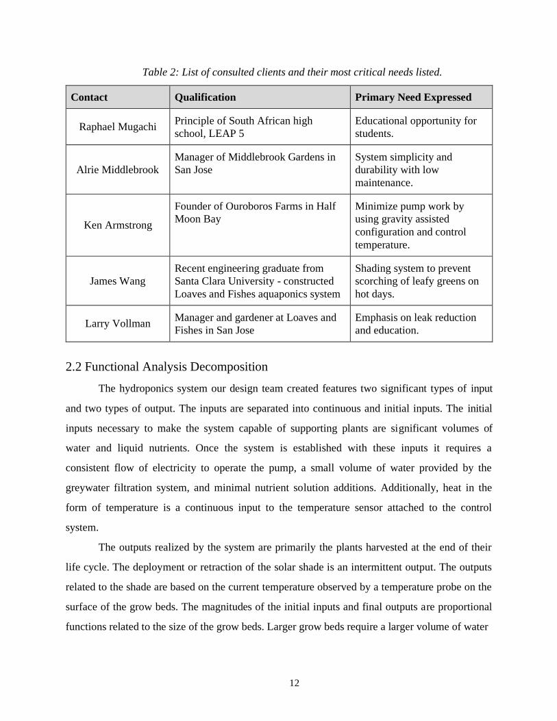
Table 2: List of consulted clients and their most critical needs listed.
Contact Qualification Primary Need Expressed
Raphael Mugachi Principle of South African high
school, LEAP 5
Educational opportunity for
students.
Alrie Middlebrook
Manager of Middlebrook Gardens in
San Jose
System simplicity and
durability with low
maintenance.
Ken Armstrong
Founder of Ouroboros Farms in Half
Moon Bay
Minimize pump work by
using gravity assisted
configuration and control
temperature.
James Wang
Recent engineering graduate from
Santa Clara University - constructed
Loaves and Fishes aquaponics system
Shading system to prevent
scorching of leafy greens on
hot days.
Larry Vollman Manager and gardener at Loaves and
Fishes in San Jose
Emphasis on leak reduction
and education.
2.2 Functional Analysis Decomposition
The hydroponics system our design team created features two significant types of input
and two types of output. The inputs are separated into continuous and initial inputs. The initial
inputs necessary to make the system capable of supporting plants are significant volumes of
water and liquid nutrients. Once the system is established with these inputs it requires a
consistent flow of electricity to operate the pump, a small volume of water provided by the
greywater filtration system, and minimal nutrient solution additions. Additionally, heat in the
form of temperature is a continuous input to the temperature sensor attached to the control
system.
The outputs realized by the system are primarily the plants harvested at the end of their
life cycle. The deployment or retraction of the solar shade is an intermittent output. The outputs
related to the shade are based on the current temperature observed by a temperature probe on the
surface of the grow beds. The magnitudes of the initial inputs and final outputs are proportional
functions related to the size of the grow beds. Larger grow beds require a larger volume of water

13
and liquid nutrients supplied initially. Much like the initial inputs, the single output of harvested
crops varies proportionally to the size of the grow beds. A larger grow bed also requires a larger
pump, but the scaling is not linear in relation to the area occupied by the grow bed like the water
and nutrient volume. Pump sizing is primarily a function of head height observed and length of
pipe which the water must travel before returning to the pump. The intermittent output realized
by the shading system is consistent with the weather patterns of the region and the programmed
deployment and retraction temperature.
2.3 Existing System Benchmarking
There are various hydroponics systems currently on the market ranging in size and cost.
Table 3 summarizes the variety of systems. Each of these commercial systems will be used to
complete a benchmarking analysis.
Table 3: Summary of Current Hydroponic Systems on the Market
Name
Manufacturer
Reservoir
Size
[gal]
Grow Bed
Size [ft2]
Price
Aquasprouts Fountain [11] AquaSprouts 6 0.8 $159.65
Miracle-Gro AeroGarden
Harvest Elite [12]
AeroGarden
1/2
0.6
$169.95
Hydroponics EuroGrower 8 Site
Complete [13]
HTG Supply
6
40
$616.65
Ebb & Flow Hydroponic Flood
Table Kit [14]
ActiveAqua
70
16
$768.95
Hydroponic Drip System Flood
Table Kit [15]
Botanicare
115
32
$1089.95
Aquabundance
Home Aquaponics System [16]
The Aquaponic
Source
200
45
$7,895.00
14
2.4 Rationale for System Specifications
Through the help of research and benchmarking commercial systems, our team set out a
list of aspects that we wanted to include in our final design. Table 4 ranks customer needs is
ranked from 1-5 with 1 corresponding to a low priority and 5 corresponding to a high priority.
Table 4: Customer needs. Higher numbers equates to higher priority.
#
Subsystem
Need
Priority
(1 - 5)
1
Software Simplistic design for both students and teachers to
interact with
5
2 Water Ability to be reuse throughout system 5
3 All Operational in rain and inclement weather 5
4 Structural Design Ability to hold various loads (growth of plants) 5
5
Electronics/ Hardware/
Structural Design
Replacement of parts is seamless and easy to
accomplish for students and teachers alike.
3
6 Structural Design Safety 5
7
Electronics
Arduino operated and connected to sensors
throughout system
5
8 Piping Dependability/Minimal leakage 4
9 Structural Design Weather resistance 5
10 Structural Design Durability 5
11 All Ability to be recreated at other LEAP Schools 2

15
12 Electronics Longevity 4
13
Electronics
Ability to use electrical power from school and is
low power
5
14 All Simple educational training 3
15 All Cost effective 3
16 All Items needed purchased in South Africa 4
17 Structural Design Sun shading system 5
18 Control System Monitor and control surface temperature 4
19
Water Pump
Dependable, suitable for size of system,
submersible
5
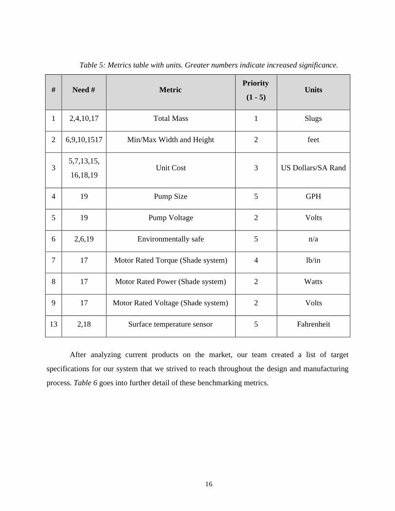
Variables including total mass, pump voltage, and motor ratings were additionally
weighed in a metric to determine their relative importance. The most significant factors were size
of the pump due to power usage and temperature range of the temperature probe so that
environmental conditions could be controlled.
16
Table 5: Metrics table with units. Greater numbers indicate increased significance.
#
Need #
Metric
Priority
(1 - 5)
Units
1 2,4,10,17 Total Mass 1 Slugs
2 6,9,10,1517 Min/Max Width and Height 2 feet
3
5,7,13,15,
16,18,19
Unit Cost
3
US Dollars/SA Rand
4 19 Pump Size 5 GPH
5 19 Pump Voltage 2 Volts
6 2,6,19 Environmentally safe 5 n/a
7 17 Motor Rated Torque (Shade system) 4 lb/in
8 17 Motor Rated Power (Shade system) 2 Watts
9 17 Motor Rated Voltage (Shade system) 2 Volts
13 2,18 Surface temperature sensor 5 Fahrenheit
After analyzing current products on the market, our team created a list of target
specifications for our system that we strived to reach throughout the design and manufacturing
process. Table 6 goes into further detail of these benchmarking metrics.

17
Table 6: Benchmarking metrics for project’s system (Target Specs).
#
Metric
Priority
(1 - 5)
Units
Marginal
Value
Ideal Value
1 Total Mass 3 Slugs >5 <8
2
Min/Max Width and
Height
4
feet
>5x5x5
<7x7x6.5
3
Unit Cost
3
US
Dollars/SA
Rand
<5000
~2000
4 Pump Size 5 GPM >400 ~550
5 Pump Voltage 3 Volts >200 ~230
6 Environmentally safe 5 n/a Yes Yes
7 Motor Rated Torque 4 lb/in >2 ~3
8 Motor Rated Power 4 Watts >1/16 1/12
9 Motor Rated Voltage 4 Volts >100 ~130
13
Surface Temperature
Sensor
5
Fahrenheit
>60
<80
2.5 System Configuration
Our team drafted, designed, and constructed a comprehensive hydroponic system that
would fit within the parameters set out by our partner, LEAP 5 High School. Our system
comprises multiple subsystems that are strategically interconnected in order to provide a
working, viable system. In general, our project employs two different styles of grow beds, a raft

18
bed and a wicking bed, to accomodate a larger range of vegetables in our system. Nutrients are
delivered to the vegetables through a water recirculation system that prevents any unwanted
water runoff that is found in traditional agricultural methods. To protect temperature sensitive
plants, we designed a shading structure that would deploy a greenhouse shading material over
the grow beds. Another aspect of the system layout is our greywater filter. Greywater refers to
any wastewater that does not contain fecal matter. Since one of the primary goals of our project
is to reduce the use of freshwater for agricultural needs, we developed our system around the
reuse of greywater. A greywater filter is installed in the basin of a repurposed bathtub to filter
fine mulch particles in order for the water to be safely introduced to the grow bed system. This
system layout was promoted by the notion of designing a system to ultimately educate, reduce
water waste, and produce vegetables.
The system cycle begins at the 55 gallon water reservoir in the center of the layout, a
submersible pump draws water from the reservoir to the two raft beds on either side. The one
pump supplies the water intake for both smaller cycles. Water slowly flows through the raft beds
until it drains out the opposing end and into the wicking bed. When water reaches this secondary
bed, a porous PVC pipe enables the water to distribute throughout the media. When the water
level reaches a determined height, it then exits the first wicking bed and flows into the second.
Again, the identical water flow process is completed in the second wicking bed compared to the
first. Finally, the water is delivered back to the reservoir for the process to begin again. This
same process is mirrored on both sides of the system.

19
Figure 6: South Africa hydroponic system layout.
2.6 Project Management
The interdisciplinary nature of the project led to considerable overlap between
departments as the holistic goal of delivering a hydroponic system was sought after.
2.6.1 Design Challenges and Goals
The project team came up with a preliminary list of challenges and constraints with our
partners at LEAP 5 High School that were essential to the success of the project. Members from
each department were assigned goals complementing their strengths as shown in Table 7.
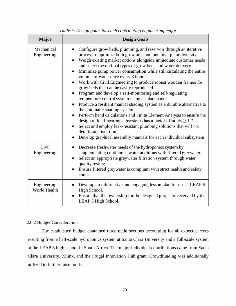
20
Table 7: Design goals for each contributing engineering major
Major Design Goals
Mechanical
Engineering
● Configure grow beds, plumbing, and reservoir through an iterative
process to optimize both grow area and potential plant diversity.
● Weigh existing market options alongside immediate customer needs
and select the optimal types of grow beds and water delivery
● Minimize pump power consumption while still circulating the entire
volume of water once every 3 hours.
● Work with Civil Engineering to produce robust wooden frames for
grow beds that can be easily reproduced.
● Program and develop a self-monitoring and self-regulating
temperature control system using a solar shade.
● Produce a resilient manual shading system as a durable alternative to
the automatic shading system.
● Perform hand calculations and Finite Element Analysis to ensure the
design of load-bearing subsystems has a factor of safety ≥ 1.7.
● Select and employ leak-resistant plumbing solutions that will not
deteriorate over time.
● Develop graphical assembly manuals for each individual subsystem.
Civil
Engineering
● Decrease freshwater needs of the hydroponics system by
supplementing continuous water additions with filtered greywater.
● Select an appropriate greywater filtration system through water
quality testing.
● Ensure filtered greywater is compliant with strict health and safety
codes.
Engineering
World Health
● Develop an informative and engaging lesson plan for use at LEAP 5
High School.
● Ensure that the ownership for the designed project is received by the
LEAP 5 High School.
2.6.2 Budget Consideration
The established budget contained three main sections accounting for all expected costs
resulting from a half-scale hydroponics system at Santa Clara University and a full-scale system
at the LEAP 5 high school in South Africa. The major individual contributions came from Santa
Clara University, Xilinx, and the Frugal Innovation Hub grant. Crowdfunding was additionally
utilized to further raise funds.

21
2.6.2.1 Expenses
Our group has seeked funding from the Undergraduate School of Engineering Program
for the materials total. The materials detailed in our budget has covered the construction and
operational functions of two hydroponics systems - one in Santa Clara, CA and one in Jane
Furse, South Africa. Our Santa Clara prototype allows us to gain hands on experience with the
plumbing, controls system, shading structure, and agriculture components. In doing so, our team
has gained the knowledge required to optimize the system’s growing conditions. Gaining this
knowledge of the complete system has allowed us to replicate the design for LEAP 5 School.
Table 8: Cost of materials used to prototype the system in Forge Garden, Santa Clara.
CATEGORY COST
Raft Bed $363.19
Plumbing $35.94
Wicking Bed $65.36
Greywater Filter $134.45
Shading Structure $278.37
Controls System $19.38
TOTAL: $896.69
2.6.2.2 Income
In addition to seeking funding from Santa Clara University and from the Xilinx grant, we
have set up a funding campaign on the crowdfunding website, GoFundMe. This campaign has
been primarily aimed at obtaining donations from friends and relatives. However, this
crowdfunding page has also been used to advertise our project to the public and to any
organizations who may want to contribute to the cause.

22
Table 9: Fundraising sources/amounts
Fundraising
Source Amount Note
School of Engineering Grant $2,000 Grant for engineering students.
Crowdfunding (GoFundMe) $2,710 Contributions from friends and
relatives.
Xilinx Senior Design Grant $3,500 Enables travel for projects with
remote sites.
Frugal Innovation Hub Grant $3,000 Supports travel expenses.
Engineering World Health Funding $2,000 Funding for Engineering World
Health students
2.6.3 Timeline
Our team succeeded in establishing and complying with an ambitious timeline in order to
ensure the successful completion of our system in South Africa. The planned departure date was
March 20, 2020 and our group accelerated our construction and validation efforts in order to
produce a product which would satisfy the needs of the LEAP 5 High School.
The Gantt chart, shown in Table 10, was created so that project action items were
completed in a timeline conducive to rapid development. A more detailed table provides specific
dates to track planned completion of items against their actual completion. Our team successfully
managed to complete the majority of key milestones on the aggressive schedule which promoted
project completion before the planned deployment at the High School in South Africa.

23
Table 10: Timeline of key tasks
Action Fall 2019 Winter 2020 Spring 2020
Research
Prototyping
Finalizing Design
Manufacturing
Verification & Testing
The initial research and conceptual designs were the most time consuming and under-
scheduled tasks our team encountered. Our team decided to invest our time in research,
prototyping, and conceptual design because of the firm March 20th deadline. Initial testing and
designs were proved effective before major construction occurred. Once the designs were
validated through a prototype, rapid full scale construction was completed with few setbacks.
2.6.4 Risks and Mitigations
It is essential to determine any potential risks that can come about during designing,
manufacturing, and deploying a successful product especially when it comes to an agricultural
system. Below is a list of potential risks that were considered throughout the senior design
project.
Figure 7: Overview of project schedule timeline.

24
2.6.4.1 Risks
Several physical hazards were identified before the construction of our system. The hazards were largely
due to the labor involved in producing hardware constructed of wood, metal, and plastic. Chemical agents
due a pH adjuster and chemical sealants were also cited as potential means for minor injury or irritation.
The operations relevant to the project were deemed to be low risk for injury because of proper hazard
investigation and training.
Table 11: Detail of hazards which may incur during manufacture of project.
Item Physical Hazard or Agent
1
Operation of power tools and equipment to cut, fasten, and drill both wood,
ABS pipe, and PVC pipe. There is a potential to maim oneself with
improper power tool operation.
2
Team members trimming plants and plant-root substrates using snips or
knives could be injured.
3
Use of fertilizers and pH adjusters (phosphoric acid and potassium
hydroxide) since skin contact can cause minor dermal irritation
4
Skin irritation due to sunlight exposure and physical labor in Santa Clara
University Forge garden
2.6.4.2 Mitigations
For every hazard identified, at least one mitigative action incurred. All preventative
actions were confirmed with University officials to ensure that both the safety of the team
members involved in construction in addition to any individuals who may come in contact with
the system would not be injured.

25
Table 12: Detail of preventative actions taken by team to remedy potential hazards.
Item Risk Mitigation Action
1 All team members underwent powertool training and certification at Maker Lab.
2 Extreme caution will be executed with sharp objects.
3
Appropriate street clothing (long pants, closed toed shoes), safety glasses will be used
in working environments when operating any power and hand tools.
4
All team members reviewed safety precautions and know to thoroughly rinse if
irritation occurs.
5 Nitrile gloves will be used when handling fertilizers and pH adjusters.
6
Follow all instructions from Forge Garden Organic managers and maintain compliant
with their rules and regulations when on premises.
2.6.5 Team Management
In order for this project to be successful in this brief time period of six months, each team
member was assigned to manage a specific subsystem. While there was a lead for every
subsystem, our team emphasized collaboration with each other and would always seek others
advice, ideas, and help when it came to complete these sections of the project.
Alex Estrada was tasked with being the lead of the shading structure. After the team’s
concept selection, Alex focused on work with Civil Engineering Lab Manager, Brent Woodcock.
Over the six month course, they collaborated on the construction of the shading frame, stepper
motors operation, building manuals, and the structural integrity of the entire subsystem to
promote safety and effectiveness.
Kathryn (Katya) Fairchok was in charge of pump flow design and calculations. She
calculated flow rate and head loss in the system based on material roughness and geometry, and
she identified the pumps to be used in the system. Additionally, Katya was in charge of the
Blynk app development. She worked on the circuitry for the temperature sensor, the code for the

26
wifi chip transmitting data to the app, and the app interface. Katya also was in charge of all
fundraising efforts, material, and donation management. Finally, Katya performed the CAD
development and graphic design for the system components.
Andrew Feldmeth developed project timelines and led research and construction of
hydroponics grow beds and plumbing orientation. Critical industry contacts were established
through connections made by Andrew Feldmeth. The commercial connections provided useful
insight and feedback on our approaches to creating an effective hydroponics system. Additional
effort was dedicated purely to ensuring that the hydroponics system was easily replicable,
durable, and encouraged learning outcomes for the high school students. A template of assembly
manuals for each subsystem were designed so that system owners could trace the construction of
the system from raw materials to finished product in ten steps or less through clear graphics.
Andrew Jezak was tasked with delivering sufficiently filtered greywater that was suitable
for use in a hydroponics garden. The conceptual design and preliminary prototypes were tested
for water quality by him. Along with assisting in the design and build of the grow beds,
plumbing, and shading structure, Andrew also had a role in tracking expenditures, performing
the cost- benefit analysis, and ordering materials for use in South Africa.
Biology students in the Engineering World Health program support and collaborate with
engineers on their senior design projects. EWH students specifically help the team to create
projects that are frugal, impactful, enduring, and culturally appropriate. For this project, the
EWH students focused on the creation of 15 hours of education materials. This curriculum
included lectures, experiments, activities, and daily interaction with the hydroponics system. The
most important aspects of the education materials were the connection to the hydroponics system
and the empowerment of students to make an impact in their local communities. During the
planned travel to LEAP 5, the EWH students were to implement and oversee all of the education
of LEAP 5 students utilizing the materials mentioned above.
3. Subsystems
The hydroponics system our group has built consists of five principal subsystems: grow
beds, shading structure, data logging, plumbing orientations, greywater filtration system. The

27
details of each subsystem will be discussed in the following sections. Each of the defined
challenges of the project were paired with a specific subsystem to overcome these obstacles.
Every challenge had to be deliberately addressed in a subsystem in order for our project to be
successful.
3.1 Grow Beds
The grow beds are a focal point of the hydroponics system and the success of the
subsystem is the measurement of success for the entire system. Grow beds were required to be
durable and capable of rapid construction. The final designs were largely inspired by and adapted
from observations recorded during visits to successful large-scale hydroponics and aquaponics
farms.
3.1.1 Raft Bed
The raft bed is the grow bed which provides up to 96 plants per 4’ x 8’ module. The
entire frame is built using just 2x4’s 2x6’s and a ½” thick OSB board. It is simple in that it
requires a very basic frame construction with commonly available lumber and no awkward
brackets or fixtures. Many of the large commercial farms used the same beds, but rather than
being in 8’ long sections they were 80’ long. Water is delivered to the raft bed from the nutrient
reservoir by a submersible pump on a timer. The subsystem contains the largest volume of water
in the system and acts as a buffer as the nutrient-rich water cycles through. The water in the bed
is approximately 9 inches deep and on it floats four 2’ x 4’ “rafts” which are ¾” thick styrofoam
insulation boards which contain 24 holes with a small net-pot per hole to house the plant. The
raft bed is a great system for our project because it is extremely low maintenance and very
durable. These were two defining qualifications in our grow bed selection and the raft bed
proved exceptional. The large body of water is very good in summer months too because it acts
as a thermal reservoir due to water’s high capacity for heat which helps keep plants cool.

28
Figure 8: Model of raft bed frame.
The almost 200 gallons of water housed in the raft bed weigh over 1500 lbs. and required
careful analysis to ensure that the frame could support the load. A hand-calculation strength
analysis was performed and indicated that with a beam spacing of 16 in. there would be a factor
of safety of 1.9 -- acceptable for our durability standards. These beams would be supported by
eight cinder blocks, four on each long side. The ground under the cinder blocks was levelled and
tamped to ensure that the raft bed was even and that water would not pool up. In order to validate
our hand-calculations, we devised a Finite Element Analysis, with a mesh refinement placed on
the bottom face of the beams spanning the width of the bed. These beams saw the greatest
moment, yet still remained comfortably under the yield point. The max stress was seen on the
edges which represent the worst-case scenario if the beam was only in contact with a tiny sliver
of area on the cinder block. The high stress at these worst-case edges proved to be above yield so
we could expect to see slight compression failure, but on the observed system there was a larger
contact surface area from beam to cinder block and no compression failure or surface splintering
was observed. The analysis on the raft bed further reinforces the fact that this is a hardy grow
bed and even in worst case scenarios, it can yield crops with little to no impact on its
productivity.

29
Figure 9: Finite Element Strength Analysis of raft bed frame with simulated water loading
The raft bed is the first grow bed to receive nutrients from the nutrient reservoir, before
the water flows into the wicking bed. As seen in the image on the far left, the rafts present the
opportunity to have plants at different stages in their life-cycle growing simultaneously. This
adaptability is key to our objective of providing a system that can grow multiple types of plants
simultaneously. In the photo, you can see colorful romaine lettuce (the largest), Butterhead
lettuce (medium) and arugula (the youngest and smallest). Plants are harvested by removing the
raft and trimming them at the stalk. The old roots are composted and net-pots which anchor the
root of the plant are then reused to house a new seedling. The seeds are sprouted in coco coir -- a
loamy media made from coconut fibers -- placed in propagation trays. The plants spend about
two weeks from seed to seedling before they are transplanted to their final destination in the raft.
Our first harvest of lettuce took approximately 50 days from seed to harvest which is almost two
times faster compared to lettuce that grows in the soil. The raft bed is a very ideal system to fill
the needs identified by our client the LEAP 5 high school. The ability to simultaneously grow a
variety of leafy greens at different life cycles gives the students at LEAP 5 and the gardeners at
the Forge Garden the tools to explore hydroponic growth in a wide variety. The raft bed is a
perfect high-production, high-density grow bed when paired against the more versatile wicking
bed which the water enters next.

30
3.1.2 Wicking Bed
The wicking bed is a crucial piece in our system because it allows the gardeners to grow
longer lived fruiting and flowering vegetables like broccoli, tomatoes, peppers, and even
potatoes. This is the largest strength of the wicking bed and why it compliments the shortcoming
of the raft bed. Because there is no deep, anchoring substrate in the raft bed, lighty leafy greens
are prefered. The deep soil and clay ball aggregate allows long-term plants to receive the support
they need to produce a successful yield. On the surface the wicking bed may appear just like a
normal raised garden bed but it uses a unique water delivery method. Instead of watering from
the top of the soil -- allowing a significant portion of that water to go unused due to surface
evaporation -- water is delivered through a perforated pipe along the entire length of the planter
base and it “wicks” up to the roots. The wicking is a result of the capillary action which delivers
water from the water-saturated lower layers up through the soil to the deepest roots of the plants.
Giving water straight to the roots from the bottom helps the plants grow bigger and faster. When
designing the system our team considered ebb & flow systems and drip line irrigation but found
that wicking beds again were superior due to their simplicity and less maintenance. An
advantage of wicking beds is that a small volume of soil is used, alongside expanded clay balls,
so that compost can be utilized which further boosts the productivity of the plant.
Figure 10: Model depicting the bathtub used to house the soil
and the frame.
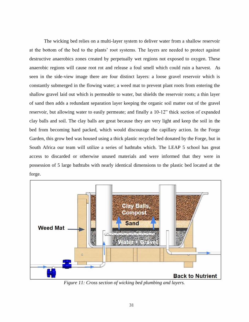
31
The wicking bed relies on a multi-layer system to deliver water from a shallow reservoir
at the bottom of the bed to the plants’ root systems. The layers are needed to protect against
destructive anaerobics zones created by perpetually wet regions not exposed to oxygen. These
anaerobic regions will cause root rot and release a foul smell which could ruin a harvest. As
seen in the side-view image there are four distinct layers: a loose gravel reservoir which is
constantly submerged in the flowing water; a weed mat to prevent plant roots from entering the
shallow gravel laid out which is permeable to water, but shields the reservoir roots; a thin layer
of sand then adds a redundant separation layer keeping the organic soil matter out of the gravel
reservoir, but allowing water to easily permeate; and finally a 10-12” thick section of expanded
clay balls and soil. The clay balls are great because they are very light and keep the soil in the
bed from becoming hard packed, which would discourage the capillary action. In the Forge
Garden, this grow bed was housed using a thick plastic recycled bed donated by the Forge, but in
South Africa our team will utilize a series of bathtubs which. The LEAP 5 school has great
access to discarded or otherwise unused materials and were informed that they were in
possession of 5 large bathtubs with nearly identical dimensions to the plastic bed located at the
forge.
Figure 11: Cross section of wicking bed plumbing and layers.

32
3.2 Shading Structure
While benchmarking and researching for our project, we noticed an outstanding issue
with a previous system. After touring the aquaponic system at Loaves and Fishes (in San Jose),
our team quickly recognized the lack of growth coming from the leafy green raft beds.
Investigating further, the volunteer farmers explained that the lack of growth was due to an
excessive amount of sun exposure and high temperature. Leafy greens can easily bolt due to an
inadequate climate. Therefore, our team set out to solve this issue in these hydroponic
agricultural systems. To ensure that the system we ultimately produce would be able to promote
the growth of leafy greens in raft beds, we decided to implement a shading structure above the
raft beds to keep the leafy greens in the ideal temperature range. Understanding that leafy greens
require both direct sunlight and reasonable climate to grow, our shading structure will be
retractable to provide direct sun exposure for parts of the day while protecting the vegetables
during daily peak temperatures.
3.2.1 Design Considerations
When it came to determining the type of shading structure, it was essential to determine
the best effective design that would work seamlessly among the other subsystems and promote
the growth of the leafy greens. Our group has produced a list of aspects and requirements for the
concepts that we developed: manufactuability, durability, materials, accessibility to grow beds,
aesthetic, effectiveness, and assembly. Once the designs were complete, according to these
aspects and requirements, they were analyzed and rated on a scaling system of 1-5 (with 1 being
the least desirable and 5 being most desirable). Once the scoring was completed, the points were
summed and compared among other design scores to determine which option best fits our system
requirements.
Each of the following shading systems designs utilizes a sun shading cloth that,
depending on the grade, only allows a certain amount of sun to permeate the material. The
selection on the type of material will be discussed in further detail later in this chapter.

33
3.2.1.1 Design 1: Hand Fan Design
This first initial design was inspired by a hand fan (See Appendix A1). Throughout the
day, the ‘fan’, which is constructed of PVC and connected to a motor at the base of the grow bed
system, would expand and retract depending on the temperature reading from the control system.
There are 4 PVC pipes for each grow bed module with each bed having their own individual
shading material coverage. Looking at a single grow bed, 2 of the 4 PVC pipes would remain
vertical while the other 2 PVC pipes will be directly connected to the motor at the base in order
to deploy. The main takeaways from this first design is that there is an accessibility issue. The
grow beds require consistent maintenance, harvesting, and planting to the grow beds because of
the short radius of the shad structure and that this system requires twice the amount of material
due to its nature of 2 ‘fans’.
3.2.1.2 Design 2: Reinforced Hand Fan Design
This second design was a byproduct of the first design concept (See Appendix A2). We
recognized the issue that came about with twice the amount of material needed to operate Design
1. In consequence, we reduced the shading fabric and motor quantity to a single unit. This layout
can be described as acting like a convertible car cover. This design utilizes 10 PVC pipes (5 on
each side of the grow bed) all connected to each other by the shading material and rope. When
deployed, the structure will expand by a rotating motor connected to the PVC pipes. There will
be a total of 3 pipes on either side of the grow beds that will remain above ground level (one
vertical and two at 45 degree angles). In summary, this will be the most aesthetic design and
would guarantee shading over the grow beds but not on the sides. This design option is very
complex and may be difficult to build over the grow beds.
3.2.1.3 Design 3: Square Frame Design
This final design option is unlike the other two previous concepts (See Appendix A3).
This particular shading structure design does not wrap around the entire grow bed but instead is
propped up above the system. This concept consists of piping which is stabilized by footings.
This system will act like a horizontal garage door compared to the classic vertical doors that we
see on houses. The main takeaways are that this design would be accessible on all sides of the
growbed, would be easy to manufacture, and would be simultaneously effective.

34
After analyzing each design, Table 12 was constructed to determine which concept best
fit our set out aspect and requirements.
Table 13: Concept Selection Matrix for Shading System
Consideration Areas Design 1 Design 2 Design 3
Manufacturability 3 2 3
Durability 3 3 4
Materials 3 2 3
Accessibility to Grow Beds 2 1 5
Aesthetic 3 5 1
Effectiveness 2 2 4
Assembly 2 1 2
Total Score 18 16 22
After comparing all three designs shown in Table 12, it was determined that Design 3
would best suit our needs. While Design 1 and 2 were very close in scoring, Design 3 is the
obvious winner due to the grow bed accessibility, durability, and effectiveness.
3.2.2 Finalized Detailed Design
Our team ultimately decided to construct and design two operating systems for our final
design. Both manual and automatic operation will be the driving forces for the deployment of the
shading material. We created the manual system because we wanted to ensure that our South
Africa system could be easily maintained, reducing the amount of electronic components that
were ultimately needed for the automatic system. On the other hand, the automatic system would
be constructed and prototyped here at Santa Clara University. This motorized system alleviates

35
the duty of monitoring the hydroponics system throughout the day. While the automatic system
would be ideal, it was not feasible for manufacturing in South Africa. In both cases, the overall
design and construction of the structure are identical.
Both structures consist of ABS weather resistant pipes which are stabilized through
concrete footings. This frame-like design allows access to the grow bed from all sides of the
system. Metal cable is used as a “railing” guide to prevent the shading material from drooping
down and interfering with the grow beds below. The shading system subsystem can be seen in
Figure 12.
The overall goal of this design of the shading structure is to protect the leafy green
vegetables below from extreme high temperatures while still promoting accessibility to garden
beds. Through research, our team found that an adequate temperature range for leafy greens were
in the range of 60°F-80°F [17, 18, 19]. With this understanding that leafy greens require both
direct sunlight and reasonable climate to grow, our shading structure is to be retractable to
provide direct sun exposure for parts of the day while protecting the vegetables during daily peak
temperatures. A fully deployed and retracted system can be seen in Figure 13.
Figure 12: Shading Structure Subsystem.

36
Figure 13: Shading Structure retracted and deployed.
3.2.3 Manual Consideration
The design of the manually operated system employs a shading material that is meant for
human interaction. The shading material is woven through tensioned rope tied along the length of
either side of the structure for easy manual deployment and retraction depending on the heat
intensity throughout the day. During peak hours of the day when solar radiation and temperatures
peak, the shading material would be deployed over the grow beds by pulling the material through
the rope with minimal effort. Figure 14 depicts how the rope is strategically inserted into the
shading material’s grommets.

37
Figure 14: Rope interwoven between shading material grommets.
3.2.4 Automatic Consideration
The automatic shading structure removes the human dependence factor and is instead
being driven by inline stepper motors. This motorized system alleviates the duty of monitoring
the hydroponics system throughout the day. Motors are attached to the vertical ABS structure
and are connected to each other through a horizontal pipe where the shading material wraps
around. Both motors work in unison with each other to deploy the shade over the grow beds.
Stepper motors were chosen for our application due to the fact that their angle of rotation can be
precisely controlled and that they can possess holding torque without the need of the motor to be
powered.
Through the use of an Arduino, a connected waterproof temperature sensor on the
surface of the raft beds constantly monitors the temperature. When the sensor reads a
temperature out of suitable range for the vegetables to grow, the Arduino would then send a
signal to the stepper motors to rotate to deploy the shading material.
3.2.5 Analysis of the Shading Structure
The object of the analysis is to focus on the structural integrity of the shading system.
This system exists to provide adequate shade to the grow beds in order to prevent scorching the
vegetables due to solar radiation as well as extremely high temperatures. This scorching is due to

38
the high surface temperatures of the raft beds that would be significant enough to damage the
leafy greens. Our team set out to conduct two main analyses on the shading structure: stress and
thermal studies.
A stress analysis was conducted on the automatic shading operating system. More
specifically, a stress analysis on the ABS pipe where the stepper motors attach onto was
conducted. This test was performed to determine the durability and maximum stress of the
critical region that the part may endure. The shading material is relatively lightweight with a total
of 18 lbf being applied to the two motor pipe connections. Our group has assessed the possible
failure modes -- bearing of the ABS and shear of the bolts -- and neither appear problematic
visually. In addition to failure under the expected load of the system, a maximum allowable
vertical load before bearing failure was calculated. Our analysis specifically looks at how the
motor load will affect the strength of the framing structure, given a minimum pipe diameter, and
resolve the question of the feasibility of whether or not ABS can be used for this subsystem as
opposed to metal tubing.
A thermal analysis was conducted on the surface of the raft grow beds. It was brought to
our attention through previous senior design teams, master gardeners, as well as hydroponic
companies, that surface temperature of the grow beds are vital to the growth of the vegetables
planted in the system. Through research, our team discovered that leafy greens require a
temperature range of 60°F-80°F to prevent their growth from bolting [17, 18, 19]. Shading
materials are produced with varied shading porosity percentages in order to be used in a wide
range of applications. With this in mind, our senior design group set out to determine the
adequate shading material porosity to select in order to keep these vegetables within their
acceptable temperature range. A thermal simulation was conducted to see what type of shading
material would be required for our system to combat the direct sunlight throughout the day. The
solar shade material will ultimately be selected due to the corresponding temperatures on the
surface of the grow beds.
3.2.5.1 Stress Analysis
The critical region of the design which requires analysis is depicted below in Figure 15.
In Figure 15, equally distributed weight of the motor, tubing, and solar shade material is applied

39
on both ABS pipes evenly (See Appendix B1). The forces that are felt on the motors are then
translated to the ABS piping structure that the motor is mounted on. This entire weight must be
supported by the four bolts located on the two bearing brackets on opposite sides of the
horizontal shade tubing. The length and weight of the tubing assembly are 7 feet and 18 lbs,
respectively. While these product specifications were provided to us by each manufacturer, our
team strives to test various loads on the shading structure that would be due to forces outside of
the system (examples include: students leaning on the structure, forces applied to structure when
shading material is retracted, ect.)
Figure 15: Stress analysis was conducted on this selected ABS pipe. This pipe section can be
found on either side of the shading structure for a total of two sections.
The specific shear forces realized by the two bolts on the bracket are illustrated in the
hand drawing Free Body Diagram shown in Appendix B2. The forces experienced by the bolts in
Appendix B2 are assumed to have two degrees of freedom about the x and y-axes. These bolts
will support both the shading material as well as the motor and will connect these two items to
the main structure of the shading system. The horizontal tubing inflicts its weight in the negative-
y direction and initiates a corresponding positive-y force in the supporting bolts. The

40
only forces witnessed in the x-direction are due to the secondary shear from the weight of the
horizontal tubing assembly.
The stress analysis sought to determine the Von Mises stress due to a distributed load of
18 lbs. This load was selected because it is the combined weight of the undeployed solar shade
material, the cylindrical ABS pipe the shade is coiled around, and the cylindrical motor
assembly. The location of the load for the model is established inside the face of the two holes on
the top section of the ABS fitting where the 3/8 inch bolts fasten. Since the applied load on the
bolts are theoretically distributed evenly, each pair of bolts would support half the total load of
18 lbs (9 lbs as a pair and 4.5 lbs individually). The load on the bolts accounts for the total
distributed load generated due to the weight of the tubing assembly. The ABS has a thickness of
¼ inches, which makes it the most narrow section of the system. The small thickness and
relatively low tensile strength justify the analysis compared to other system components.
Our team expects the ABS section will not suffer any failure due to the low weight of the
tubing that is causing the external force. ABS would most likely fail due to bearing stress rather
than shear because of the thin wall thickness of the pipe and the comparatively low tensile
strength. Neither case is very likely due to the low weight however. The weight is only 18 lbs in
total, therefore it is highly unlikely that any failure is observed. Hand calculations were
completed in order to determine our hypothesis (See Appendix B4 and B5 for details). The most
inexpensive and readily available ABS pipe will suffice.

41
Figure 16: FEA of top ABS section where bearing bracket fastens. Both holes were loaded with
identical force. Maximum shear stress is approximately 142 psi. The value generated by the FEA
is distant from tensile strength and therefore very secure and durable.
The FEA results shown in Figure 16 and hand calculations both establish ABS as a
workable material by a wide margin. The two methods of analysis generate different maximum
shear stresses (142 psi for the FEA and 173.7 psi for the hand calculations), but are on the same
order of magnitude and convey similar maximum loading outcomes. Neither result approaches
the tensile strength of ABS and even in the bearing stress case the factor of safety is greater than
21. The bearing failure mode is the most likely region in which the system will fail because the
ABS experiences a stress of 272.4 psi. Even in this failure mode, there is no realistic opportunity
for the ABS to fail because the material contains a tensile strength of 5903 psi. A second
calculation was performed to determine the maximum vertical load which the selected ABS
could withstand before failure is probable. The maximum force was determined to be
approximately 195 lbs. This specific section of ABS pipe can withstand a maximum vertical load
of 195 lbs, so caution must be taken so that persons do not grab hold of and exert their maximum
body weight on the pipe.

42
The two most significant learning outcomes for the FEA from this exercise are that
apparent failure modes may not actually be critical and it is necessary to investigate and analyze
external situations separate from the weight of system components. Superficially, the system
appeared very stable, the shear forces experienced by ABS and bolts were much smaller than the
tensile strengths. The most significant problem faced when performing the FEA analysis was
managing the connections on the assembly model of the shading structure. Ideally, our group
would have merged the parts to create one solid piece, but our assembly included several
different materials with varying properties, so merging and analyzing the system as a whole
would not produce a satisfactory result. The solution to connection issues was to analyze just the
critical section and create a simulated load where the bolts attach to the ABS. The conditions for
this simulation cause the case to not entirely represent the actual load and differ from our hand
calculations.
3.2.5.2 Thermal Analysis
The radiation onto the shading material itself can be observed in hand sketches in
Appendix B3. As shown in the sketch, the solar shade material needs to prevent unwanted direct
sunlight when the surface of the grow beds become too hot to host vegetable growth. It is
imperative that we determine the ideal percentage of porosity that the shading material is
required to possess. Shading material will be placed as a barrier between the sun and the
polystyrene grow beds, where we can test to discover what shade material achieves a
temperature most near the ideal range of surface temperatures (60°F-80°F) for these grow beds.
Initial radiation and material properties are listed below.
The thermal analysis was conducted when the angle of the sun produces the maximum
irradiation values. The latitude and longitude of Jane Furse, South Africa were selected to
provide an accurate assessment for the angle of radiation impacting the solar shade and grow
beds. The latitude and longitude were determined to be 24.7617° South and 29.8728° East.
Various percent porosity of solar shades were utilized to decrease the intensity of the solar
radiation and produce a variety of temperature results.
Our group expects the surface temperature to decrease on the grow beds as the solar
shade percent porosity increases. With more coverage combatting the direct radiation during the

43
day, we believe that there will be a decrease in temperature. Initial thermal hand calculations
were conducted to determine the team’s hypothesis (See Appendix B3 and B6). For this thermal
analysis the main mode of failure is temperature level departing the permissible range because
there is a possibility that the solar shade material will not have a great enough effect on the
surface of the grow beds.
Three common commercial shading materials were simulated to see how they would
affect the raft bed surface temperature. Appendix B7 shows an example of how these thermal
tests were conducted and how temperature data on the styrofoam raft beds were read. Table 13
shows the surface temperature results of the four trials conducted.
Table 14: Percent solar shade porosity tested compared to the grow bed surface temperature.
Percent Solar Shade
Porosity
Surface Temperature
[Fahrenheit]
0% 95
15% 87
50% 74.2
90% 68.7
Reviewing the thermal analysis, our team's hypothesis was correct. It was proven that by
increasing the shading percent coverage, the styrofoam grow bed’s surface temperature
decreased as a result. It should be noted that the temperature of the entire bed will not be as
constant as is shown in the CAD simulations (see Appendix B7) due to solar positioning changes
throughout the day as well as the vegetables providing some shade to the bed. It can be
concluded that a shading material of 50% porosity and higher can be used for our raft grow bed.
Since styrofoam is the most widely used grow bed media for hydroponics, we do not believe that
we need to test other materials but rather focus on how to provide the ideal growing
environments for vegetables that will use this material. To visualize the temperature and shading
percentage relationship Figure 17 was created as an aggregate of all temperatures and their

44
specific shading conditions. From the figure it is apparent that after tht 50% shading value is
reached, the slope of the temperatures is less steep.
The thermal analysis has imperfections because the complexity of a heat transfer process
cannot be adequately packaged into an environmental thermal model. The model corroborated
that increasing the radiation control of the solar shade decreases the temperature observed on the
grow bed. The exact values obtained from the model are not guaranteed as exact and should be
confirmed in physical tests. Unknown factors including other sources of radiation (reflections or
heating elements), increases in convective coefficient due to wind, precipitation and relative
humidity are not constant and a model cannot entirely account for all factors. The physical
testing will provide us the information to ultimately determine the correct percentage of radiation
control for the solar shade.
The thermal analysis provided information that directly aligned with our hypothesis -
greater shading percentage in the material correlates to a lower temperature in the grow beds.
The resulting temperatures on the surface of the grow beds were not conclusive however. The
thermal model cannot properly account for the convective losses, sources of irradiation aside
Figure 17: Non-linear relationship between shading percentage and temperature.

45
from the sun, and did not consider the latent heat associated with the relative humidity of the
climate. The factors outside of the scope of the thermal model limited the effectiveness of the
model and encouraged our group to perform extensive physical testing with a prototype to
determine the actual temperatures at the surface of the grow beds. The testing can be performed
with a thermocouple and shading materials with different shading percentages.
3.3 Plumbing
The intention of the plumbing orientation was to minimize the sizing requirements for the
pump so that a smaller, less expensive pump could function successfully. The plumbing was
entirely constructed using PVC pipe and requires a very low head height so that a relatively
small pump can effectively circulate a large volume of water. Leaks were largely prevented
through the use of special interface fittings such as bulkheads and uniseals.
3.3.1 Pump Selection
The Forge Garden system only circulates about half of the volume of water as the system
designed for South Africa, so two pumps needed to be selected. In order for us to minimize
energy usage, we needed to calculate the best pump to use for each system. It is neither good for
our energy usage nor for our hardware to use a pump which is unnecessarily large or small for
the kind of flow rate needed to sustain the system.
Head loss was calculated taking into account the relative roughness of each material in
use as well as the equivalent straight piping lengths for the fixtures in the system which alter the
direction of flow (see example calculation spreadsheet in Appendix C1).

46
Figure 18: Pump curves for each of the Active Aqua submersible pumps ideal for hydroponics,
with both systems flow requirements. [20]
Taking into account the volume of water in each system, the flow rate necessary to
deliver nutrients to the plants and prevent mosquito breeding, and the head loss due to system
components, we found the best pump sizes to be a 400 gph pump for the Forge system in Santa
Clara and a 1000 gph pump for the much larger system in South Africa.
Table 15: Volume and volumetric flow rate requirements and corresponding head loss for each
system.
South Africa System Forge System
Water Volume (gal) 485 278
Flow Rate (gpm) 8 5
Total Head Loss (ft) 8 2
We also needed to prevent leakage as much as possible, both to make sure that the plants
are getting the nutrients they need and also to prevent unnecessary water waste. Additionally, we
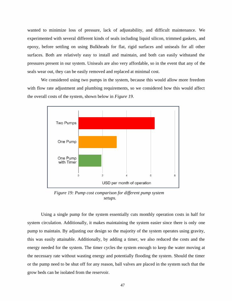
47
wanted to minimize loss of pressure, lack of adjustability, and difficult maintenance. We
experimented with several different kinds of seals including liquid silicon, trimmed gaskets, and
epoxy, before settling on using Bulkheads for flat, rigid surfaces and uniseals for all other
surfaces. Both are relatively easy to install and maintain, and both can easily withstand the
pressures present in our system. Uniseals are also very affordable, so in the event that any of the
seals wear out, they can be easily removed and replaced at minimal cost.
We considered using two pumps in the system, because this would allow more freedom
with flow rate adjustment and plumbing requirements, so we considered how this would affect
the overall costs of the system, shown below in Figure 19.
Using a single pump for the system essentially cuts monthly operation costs in half for
system circulation. Additionally, it makes maintaining the system easier since there is only one
pump to maintain. By adjusting our design so the majority of the system operates using gravity,
this was easily attainable. Additionally, by adding a timer, we also reduced the costs and the
energy needed for the system. The timer cycles the system enough to keep the water moving at
the necessary rate without wasting energy and potentially flooding the system. Should the timer
or the pump need to be shut off for any reason, ball valves are placed in the system such that the
grow beds can be isolated from the reservoir.
Figure 19: Pump cost comparison for different pump system
setups.

48
3.4 Greywater Filter
One of the main goals of the project was to conserve water when compared to traditional
soil farming. We identified an opportunity to use LEAP’s existing greywater catchment system
as our water supply for the hydroponics garden. In general, greywater refers to any wastewater
that does not contain fecal matter. In LEAP’s case, they captured water from a dishwashing sink
that is routed underground to irrigate a lawn on campus.
The scope of the greywater filter is to supplement the water lost due to evaporation
and/or leakage. Our team estimated this quantity of water to be about half of the total volume
per month (1000 L). Based on LEAP 5’s observed water production conducted by the project
team’s contacts, the surge for washing dishes in the kitchen was around 200 L/day. Assuming
that this surge would come essentially in one load as the students washed their dishes after lunch,
the capacity of the surge tank was set to handle 300 L. Since each round of dishwashing will not
be needed to top off the hydroponics garden, a tee-branch is fitted to redirect greywater to water
the existing lawn if the hydroponics system does not need to be topped off.
3.4.1 Greywater Filter Design Alternatives Analysis
The project team considered a number of different low cost and low maintenance filters.
The following alternatives were evaluated for use in this project and compared to each other for
suitability in this project.
3.4.1.1 Alternative 1: EcoSense Worm Filter
The EcoSense Worm Filter is designed for greywater filtration by removing organic
particles and grease, prior to final dispersal. It is a purchased product that would then be filled
with local materials. The main structure is a HDPE potable water tank sourced conventionally
from marine suppliers. There is a system of three screens that separates a worm filled mulch
basin and an outlet reservoir.
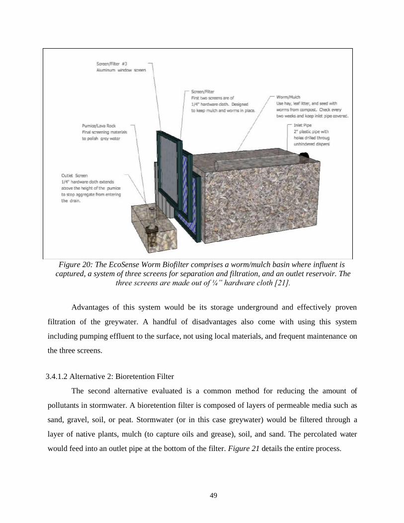
49
Figure 20: The EcoSense Worm Biofilter comprises a worm/mulch basin where influent is
captured, a system of three screens for separation and filtration, and an outlet reservoir. The
three screens are made out of ¼” hardware cloth [21].
Advantages of this system would be its storage underground and effectively proven
filtration of the greywater. A handful of disadvantages also come with using this system
including pumping effluent to the surface, not using local materials, and frequent maintenance on
the three screens.
3.4.1.2 Alternative 2: Bioretention Filter
The second alternative evaluated is a common method for reducing the amount of
pollutants in stormwater. A bioretention filter is composed of layers of permeable media such as
sand, gravel, soil, or peat. Stormwater (or in this case greywater) would be filtered through a
layer of native plants, mulch (to capture oils and grease), soil, and sand. The percolated water
would feed into an outlet pipe at the bottom of the filter. Figure 21 details the entire process.
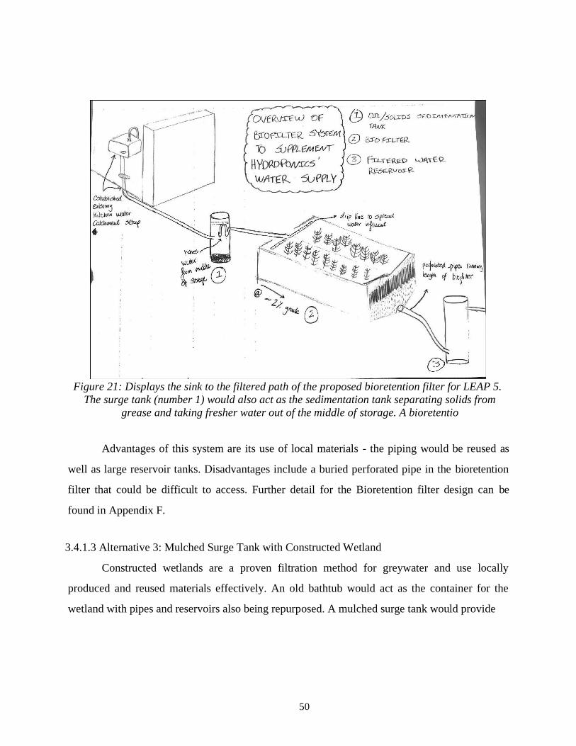
50
Figure 21: Displays the sink to the filtered path of the proposed bioretention filter for LEAP 5.
The surge tank (number 1) would also act as the sedimentation tank separating solids from
grease and taking fresher water out of the middle of storage. A bioretentio
Advantages of this system are its use of local materials - the piping would be reused as
well as large reservoir tanks. Disadvantages include a buried perforated pipe in the bioretention
filter that could be difficult to access. Further detail for the Bioretention filter design can be
found in Appendix F.
3.4.1.3 Alternative 3: Mulched Surge Tank with Constructed Wetland
Constructed wetlands are a proven filtration method for greywater and use locally
produced and reused materials effectively. An old bathtub would act as the container for the
wetland with pipes and reservoirs also being repurposed. A mulched surge tank would provide
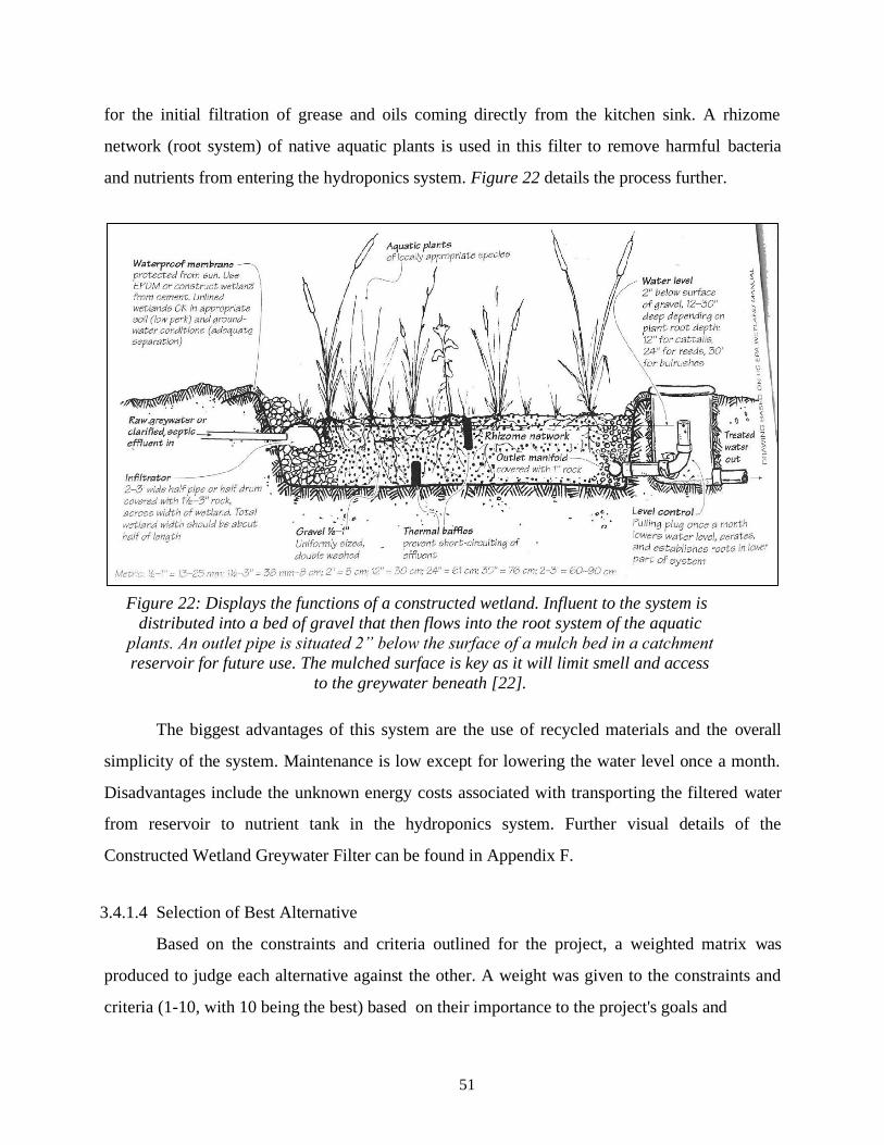
51
for the initial filtration of grease and oils coming directly from the kitchen sink. A rhizome
network (root system) of native aquatic plants is used in this filter to remove harmful bacteria
and nutrients from entering the hydroponics system. Figure 22 details the process further.
The biggest advantages of this system are the use of recycled materials and the overall
simplicity of the system. Maintenance is low except for lowering the water level once a month.
Disadvantages include the unknown energy costs associated with transporting the filtered water
from reservoir to nutrient tank in the hydroponics system. Further visual details of the
Constructed Wetland Greywater Filter can be found in Appendix F.
3.4.1.4 Selection of Best Alternative
Based on the constraints and criteria outlined for the project, a weighted matrix was
produced to judge each alternative against the other. A weight was given to the constraints and
criteria (1-10, with 10 being the best) based on their importance to the project's goals and
Figure 22: Displays the functions of a constructed wetland. Influent to the system is
distributed into a bed of gravel that then flows into the root system of the aquatic
plants. An outlet pipe is situated 2” below the surface of a mulch bed in a catchment
reservoir for future use. The mulched surface is key as it will limit smell and access
to the greywater beneath [22].

52
objectives. After this was determined, each alternative was ranked in performance for each
constraint and criteria. The final score was calculated by multiplying the weight and performance
for each alternative.
Table 16: Performance of alternative greywater filters based on established criteria.
Rating (1-5) Score = Weight x Rating
Criteria
Weights
(1-10)
EcoSense
Worm
Filter
Bioretention
Filter
Mulched
Constructed
Wetland
EcoSense
Worm
Filter
Bioretention
Filter
Mulched
Constructed
Wetland
Simplified 7 3 4 5 21 28 35
Low Maintenance 8 2 4 4 16 32 32
Safety of
Greywater
Storage
9
4
3
4
36
27
36
Uses Recycled
Materials
6
1
4
4
6
24
24
Minimal
Adaptation to
Existing System
4
2
3
3
8
12
12
Minimize Energy
Consumption
3
3
5
4
9
15
12
Durability/
Resilience to
Surrounding
Environment
5
4
4
5
20
20
25
Easy Access for
Maintenance
2
3
2
4
6
4
8
TOTAL SCORE: 122 162 184
According to the matrix, a Mulched Constructed Wetland scored the highest. This design
was further manipulated in order for it to be a part of our Preliminary Design in the following
section.
3.4.2 Greywater Filter Final Design
Initially, a constructed wetland and bioretention filter were tested to determine their
effectiveness. The vertical bioretention’s slow infiltration rate was not ideal; and, the constructed

53
wetland would remove nitrates and nitrites from the water which could be a source of nutrients
for the growing vegetables. By suspending the greywater in just mulch for at least an hour, the
undesired soaps and oils present would be soaked up allowing cleaner water to pass through. The
filter uses a repurposed bathtub and impermeable baffles to promote water circulation and
maximum surface contact with coarse mulch. A mesh sediment strainer at the end of the filter
catches fine mulch particles that exit with the effluent. The final design is shown in Figure 23.
3.5 Controls and Data Logging
The self-monitoring controls system served as a feature of the educational curriculum, to
aid in real-time data collection. The main control/data logging system involved a temperature
sensor probe on the surface of the grow beds connected to the Blynk app, a digital dashboard
where iOS and Android phones can control an Arduino with a graphic interface. To determine
what the temperature threshold is for scorching of the plants and to also inform the students what
the temperature of the raft beds is at any given time, our team decided to use a digital, waterproof
temperature sensor which is attached to the surface of the raft beds at all times. This sensor is
connected to a Node MCU wifi chip which broadcasts the temperature reading over wifi. This
Figure 23: Greywater filter orientation at LEAP 5.
54
chip uses Arduino code, so we wrote a program to read the sensor data and send it over wifi to the
Blynk app IoT platform. This code, shown in Appendix D1, takes readings in both Fahrenheit and
Celcius every second. Using the Blynk app development tools, We created a user interface which
displays the numerical values for the reading as well as a live histogram for up to a month of data.
However, to be able to analyze the data, the students need to be able to manipulate the
graphs and add labels to critical values. We set it up so the students can export the raw data in the
form of a csv file to a template excel spreadsheet which automatically adjusts the axes to
appropriate ranges and adds callouts for the maximum and minimum temperatures experienced
by the plants (see Appendix D2). The students will create these graphs on a weekly basis, and
they will then be able to see trends in the data which might affect the crop health.
This interface was tested effectively using a temperature probe, and pH and electrical
conductivity (EC) probes will be added to fully survey the system. By including a data collection
system, the students would be able to develop their own experiments using the system and
analyze data to confirm hypotheses.
4. Results
The early completion of a fully functioning hydroponics system provided our team with
one harvest of approximately 40 heads of lettuce. The results were mixed due to limited
accessibility to the Forge Garden, yet the romaine and butterhead lettuce fared excellently in the
spring conditions.

55
Figure 24: 50-day growth of butterhead (left) and tri-color romaine lettuce (right).
The success of the lettuce verified that a raft grow bed is capable of supporting a plant
density of four plants per square foot with no significant nutrient deficiencies. The beds featured
an approximately 80% survival rate with no pesticides and only a single large liquid nutrient
addition at the beginning of the life cycle. The liquid nutrients used were entirely organic and
sourced from plant extracts. The macronutrients had a balanced NPK and no micronutrients were
added. An additional arugula raft was planted but all crops bolted likely due to a specific lack of
nutrients. The two types of lettuce fared very well and grew rapidly despite the low macronutrient
levels and the lack of micronutrients.
Significant plant growth was observed in the wicking bed. Eight tomato plants were
planted in the wicking bed and after 60 days all plants have survived and expanded rapidly. Metal
cages were added to the wicking bed so that the rapidly growing tomato plants would have
additional structure to support their stems and stalks when the plant begins to produce tomatoes.

56
Figure 25: Significant tomato growth in the wicking bed (foreground) and leafy greens in raft bed
(background).
4.1 Filtered Greywater Quality
One of the main goals of this project was to conserve freshwater. Instead of utilizing the
already limited freshwater source in the Limpopo region of South Africa, our team was
determined to solely utilize kitchen greywater to fill our grow beds. A final design of the Mulch-
Retention Filter for the greywater was constructed and tested for water quality using a kitchen
sink greywater in Santa Clara shown in Figure 26. The test determined how effective the filter
was to lower the nitrate, nitrite, total hardness, total alkalinity and pH levels of the greywater to
prove if it was safe to use in the hydroponics system.

57
Figure 26: Measured water quality difference between kitchen sink greywater and after it has
passed through the Mulch Retention Filter compared to optimal vegetable growing parameters.
Parameters tested include nitrates, nitrites, total hardness, total alkalinity, and pH.
Figure 26 shows that the mulch greywater filter decreased total hardness by 50%, total
alkalinity by 20%, and pH by 2. The project team anticipates that the pumped groundwater in
Jane Furse will differ from that in Santa Clara, especially with respect to total hardness and
alkalinity. Nitrates will be added to the system from an outside nutrient solution introduced to the
system. Through this filter testing, our team was able to determine that we would be able to
successfully deploy a hydroponic system that is directly fed by greywater instead of utilizing vital
freshwater that can be rather used for human consumption. This outcome proved to be a positive
environmental impact that would ultimately alleviate the already strained freshwater supply in the
region.

58
5. Sustainability Analysis The conservation of clean drinking water was a major focus in the design of the
hydroponics garden. Low water usage was made possible through efficient grow beds and a
greywater filter to incorporate existing greywater of unknown quality. Energy usage was
additionally decreased due optimal pump sizing and the timer which regulates the uptime of the
water pump.
5.1 Water Savings
Using our data from the prototypes first lettuce harvest, a water savings analysis was
conducted to determine the system’s usage compared to a raised bed soil garden. The baseline
soil garden assumed the same grow area as the hydroponics garden with a 4 inch depth of
irrigation every 4 days. The hydroponics garden is assumed to have replaced ½ the total volume
of water each month. With these assumptions in mind, an annual projection of expected produce
yields and the gallons of water used per pound were calculated. Results are shown in Table 17.
Table 17: Water savings and annual yield comparison between the hydroponics design and a soil
garden baseline with the same grow area.
Type of System
Annual Yield [$]
Water Usage per Lb. [gallon/lb.]
Hydroponics
Garden
$1,068.62 3.90
Baseline Soil
Garden
$431.05 8.25
The hydroponics garden tested in Santa Clara’s Forge Garden used less than half of the
water and produced over two times the yield when compared to a baseline soil garden. Results
were gathered from the prototypes first romaine lettuce harvest and compared to a Cornell
University study’s soil production [23].
5.2 Energy Savings
The design and development of a greywater hydroponics system mitigates many
negative impacts of conventional agriculture, including the inefficient use of water, large land

59
requirements, dependence on concentrated and toxic pesticides, and soil degradation through
erosion.
5.2.1 Assumptions Related to the Use of Our Project and the Scope of Influence.
Several factors were assumed in the construction of the hydroponics system. Most
factors were centered around the durability and sustainability of the project. Focus was placed on
energy and water savings as well as utilization of commonly available resources. Assumptions
are as follows:
● Significantly reduced water usage compared to traditional farming
● Electricity costs that are outweighed by the freshwater water savings and increased crop yield.
● The materials utilized to construct the system are reused as much as possible and are otherwise
sustainable in their production.
● Our system will be more environmentally friendly since it is designed to fit the school’s needs
rather than retrofitting an existing commercial system for the necessary production size.
5.2.2 Materials Environmental Analysis
Using readily available materials at the school in South Africa as well as a mixture of both
plastic and wood, the energy use for our system is significantly lower than that of a commercial
system made entirely of plastic and metal shown in Figure 27. Additionally, the flow design of
our system requires only one pump to operate whereas the commercial system needed eight, one
for each of the grow beds. Compared to completely packaged, commercial systems our
hydroponics product is much less expensive per square foot of grow space and does not rely on
entirely new materials. The materials used in constructing our design can be repurposed from past
projects and sourced locally. Commercial products on the market do not have this advantage and
also must require shipping which amounts to transportation costs and significant emissions.
Purchasing a commercial system does provide nearly as much ownership of the system either
and if a piece breaks it likely must be replaced using spare parts sold by the

60
company, which will amount to further transportation costs and emissions.
By discovering new ways that greywater can be used, our team was able successfully
provide an agricultural system that does not require freshwater intake. Instead, this freshwater can
be used by both students and faculty for drinking in a region that is greatly affected by climate
change and limited access to clean water. Ultimately, our system conserves the use of freshwater
by only needing greywater to grow our crops. The economic analysis conducted helped us come
to the conclusion that our system utilizes close to 4 times less water per pound of produce with a
shorter payback period compared to traditional soil based farming. The reduction of fresh water
usage due to the greywater system is also accompanied by a reduction in the energy used to
manufacture the system in the first place. By reducing the amount of plastic used in the system
and by combining the raft bed and media bed reservoirs, we created a more energy-efficient
system than what is currently commercially available.
Figure 27: Graphical representation of the energy use of the South African system compared
to the energy use of a Commercial Setup, retrofitted to produce the same grow space as the
project system over the course of a 1- year use time. Energy use in categories of energy from
materials used, manufacturing processes, the use life of the product, and the End of Life
(EoL) potential are compared in the figure above. Graph made using the CES EduPack Eco
Audit program [24]

61
6. Business Plan
The adaptive hydroponics garden product was created to primarily service local farmers
with a limited budget and minimal access to drinking water. The primary stakeholders related to
the product benefit from the creative, durable, and adaptable design. The hydroponics product is
non-profit and attempts to diminish the barriers so that small, non-technical farmers may utilize
the benefits of hydroponics farming.
6.1 Business Plan Executive Summary
Regions with limited access to freshwater and agricultural households with limited
access to many acres of land are the targeted market for hydroponics. The potential for high
density growth regardless of soil quality is extremely appealing to regions where bountiful
harvests may be impossible due to geographic or weather factors. The low price point and highly
customizable nature of the systems give the hydroponics farmer the freedom to build and expand
what works and move away from what does not. The most significant limiting factor to the
hydroponics market is the initial price point. Driving the price down through the use of local and
recycled or repurposed goods assists the designed hydroponics system in overcoming the hurdles
that have stifled the growth of the industry. The simple design as displayed in the assembly
manuals additionally reduces the perceived complexity and improves the durability of the
product, granting a reliable sense of ownership to the buyer.
6.2 Perceived Markets
The prime market for the hydroponics product are agricultural households who depend
on a stable production of crops to feed their family or sell to generate income. The greater
markets are very broad and applicable to the suburban gardener interested in an alternative
method, an urban gardener who wants to make good use of their limited growing space in a
sustainable manner, or the industrial farm interested in scaling up production without the need for
additional harmful chemicals added to the topsoil. The large-scale industrial application is
especially beneficial to facilities which have an excess of greywater. The filtration system in
series with the hydroponics grow beds provides unmatched energy and water savings. Profits
associated with

62
the density and rapid production advantages of hydroponics over traditional methods are scalable,
so expansive farms have the potential to generate significantly more revenue. In the financial
studies conducted using our product, the density of hydroponics is four times greater than that of
traditional soil farming. The expanded yield compounds with the 60% faster growth rates seen in
our hydroponics garden compared to soil farming.
The most significant advantages our product displays is due to the collaboration with
local farmers who will be the primary stakeholders in the product. The needs expressed by the
primarily low-income agricultural community were centered around durability of the system, a
wide range of crops supported, and high yield. These needs were referenced constantly and
developed through dialogue between the stakeholders and the designers of the farming system.
The critical local input and high level of adaptability makes the product very attractive compared
to existing products on the market. Nearly all existing products are very discrete in the materials
and the method of construction required to produce the hydroponic system which leaves little
room for local specification. The existing markets feature primarily self-contained systems which
have significantly higher expenses per yield. The product designed by our team is extremely
affordable if the overall yield is compared to the initial costs and the local farmer will regain their
investment after just a year and a half of steady production.
6.3 Business Objectives
The goal of our product is to provide information about hydroponics so that farmers in
targeted areas may choose to employ hydroponics and improve their agricultural situation while
decreasing their fresh water needs. The objective of the product is to disperse catered information
about the benefits of hydroponics through the success of the physical system. The hydroponics
system is an effective tool for the small or large scale agriculture to insulate themselves from the
mounting water scarcity and insecurity in primarily impoverished regions threatened by the
effects of climate change. The primary objective is supported through the significantly lower
price point, without compromising quality or production. A lower cost of entry helps dissolve the
barriers preventing widespread access to hydroponics systems especially in impoverished
regions. Water is transported from a nondescript 50 gallon barrel, which could

63
be substituted if an existing hard-walled, plastic water container is already available, to two
unique grow beds. Each grow bed is capable of growing plants up to four times as densely as
traditional farming because of the availability of nutrients in the steady-stream of water. A
shading system, either automated or manual, provides climate control for the grow beds and a
greywater filter constructed from commonly available materials conditions kitchen wastewater so
that it can be inputted into the grow beds water supply. Our product details specifically how to
construct the modular grow beds, shading system, and greywater filter.
The sustainability of the product is augmented by the non-physical nature of the system.
The designed hydroponics system is not reliant on specific materials, rather it is scaffolding with
which to create a customized hydroponics system specific to the environment of the customer.
The primary product is information which will lead to successful plant yields, greater than yields
that could be accomplished using traditional soil farming. The provided assembly manuals are
reflective of our successful experimentation with hydroponics, but the geometries, materials, and
sizes of all subsystems are open-ended so that the customer has some creative license given their
specific environment.
6.4 Manufacturing
The hydroponics garden system is reliant on local manufacturability. When designing
the project, significant emphasis was placed on rapid manufacturability because the construction
window of the flagship system at the LEAP 5 High School in South Africa was only five days.
Manufacturability of the system is a potential bottleneck we identified about our eventual
construction in South Africa. The bottleneck was investigated and remedied through the
construction of a half-scale prototype at Santa Clara University’s Forge Garden. Each subsystem
was constructed from start to finish and then verified with a successful crop harvest. Building
each component of the system provided a clear picture of the manufacturing duration each
component required.
One focus of the designed system is the utilization of recycled or repurposed materials We
targeted repurposed materials to build the infrastructure of our system because these materials are
often significantly less expensive, they do not require transportation because they
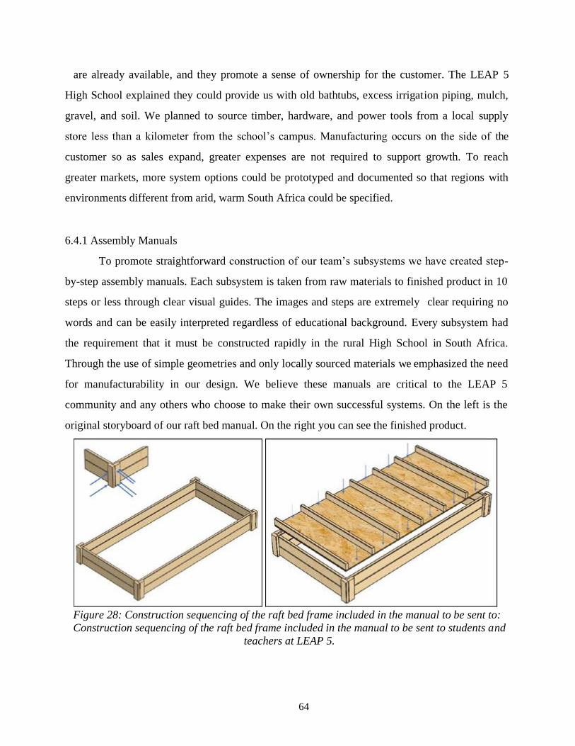
64
are already available, and they promote a sense of ownership for the customer. The LEAP 5
High School explained they could provide us with old bathtubs, excess irrigation piping, mulch,
gravel, and soil. We planned to source timber, hardware, and power tools from a local supply
store less than a kilometer from the school’s campus. Manufacturing occurs on the side of the
customer so as sales expand, greater expenses are not required to support growth. To reach
greater markets, more system options could be prototyped and documented so that regions with
environments different from arid, warm South Africa could be specified.
6.4.1 Assembly Manuals
To promote straightforward construction of our team’s subsystems we have created step-
by-step assembly manuals. Each subsystem is taken from raw materials to finished product in 10
steps or less through clear visual guides. The images and steps are extremely clear requiring no
words and can be easily interpreted regardless of educational background. Every subsystem had
the requirement that it must be constructed rapidly in the rural High School in South Africa.
Through the use of simple geometries and only locally sourced materials we emphasized the need
for manufacturability in our design. We believe these manuals are critical to the LEAP 5
community and any others who choose to make their own successful systems. On the left is the
original storyboard of our raft bed manual. On the right you can see the finished product.
Figure 28: Construction sequencing of the raft bed frame included in the manual to be sent to:
Construction sequencing of the raft bed frame included in the manual to be sent to students and
teachers at LEAP 5.
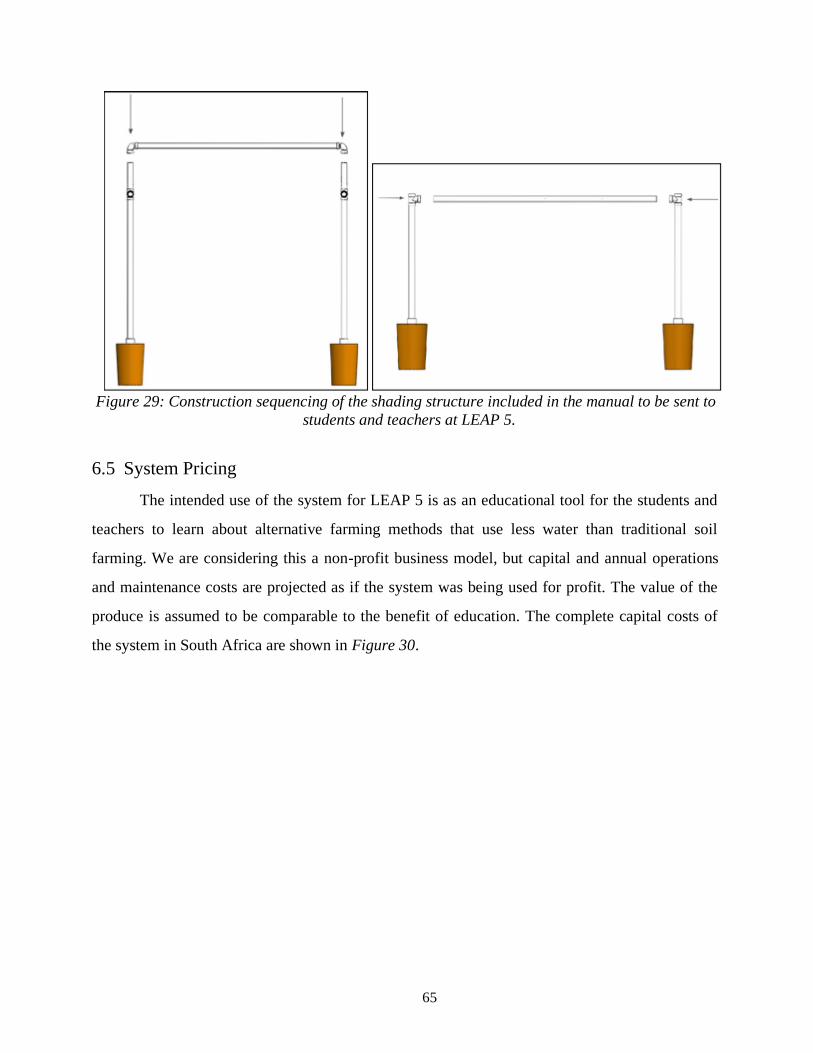
65
Figure 29: Construction sequencing of the shading structure included in the manual to be sent to
students and teachers at LEAP 5.
6.5 System Pricing
The intended use of the system for LEAP 5 is as an educational tool for the students and
teachers to learn about alternative farming methods that use less water than traditional soil
farming. We are considering this a non-profit business model, but capital and annual operations
and maintenance costs are projected as if the system was being used for profit. The value of the
produce is assumed to be comparable to the benefit of education. The complete capital costs of
the system in South Africa are shown in Figure 30.
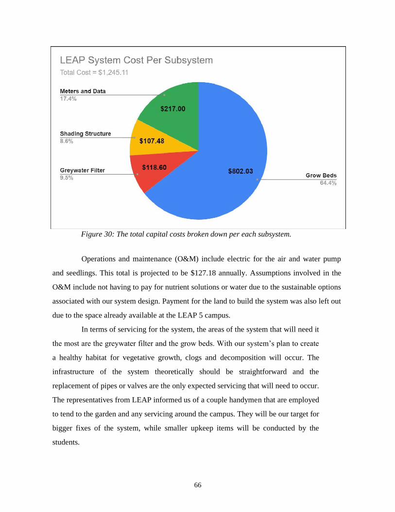
66
Figure 30: The total capital costs broken down per each subsystem.
Operations and maintenance (O&M) include electric for the air and water pump
and seedlings. This total is projected to be $127.18 annually. Assumptions involved in the
O&M include not having to pay for nutrient solutions or water due to the sustainable options
associated with our system design. Payment for the land to build the system was also left out
due to the space already available at the LEAP 5 campus.
In terms of servicing for the system, the areas of the system that will need it
the most are the greywater filter and the grow beds. With our system’s plan to create
a healthy habitat for vegetative growth, clogs and decomposition will occur. The
infrastructure of the system theoretically should be straightforward and the
replacement of pipes or valves are the only expected servicing that will need to occur.
The representatives from LEAP informed us of a couple handymen that are employed
to tend to the garden and any servicing around the campus. They will be our target for
bigger fixes of the system, while smaller upkeep items will be conducted by the
students.

67
6.6 Financial Plan (ROI)
To investigate the sustainability and affordability of the system for rural South Africa,
an economic analysis was performed to compare the LEAP 5 hydroponics garden design with
traditional raised-bed agriculture. Even though the intended use of the final system is for
educational opportunities and not for profit, this economic analysis is able to clearly compare the
benefits of hydroponics to traditional soil farming.
Sustainable initiatives which decrease operations and maintenance costs (O&M)
included with the hydroponics garden are the greywater filter and homemade compost nutrient
solutions. Yield comparisons were documented using the same growth area and $1.25 as an
average sale price of a head of lettuce. The results are shown in Table 18.
Table 18: Cost-benefit comparisons between the LEAP 5 hydroponics design and raised bed
soil farming with the same grow area. The sustainable initiatives include constructing the
Mulch Greywater Filter and using homemade fertilizer as a nutrient solution. As a result, the
hydroponics garden employing sustainable initiatives had an 83 % return on investment and an
annual profit of $1,245.21.
The Raised Bed baseline model had a 24% return on investment with a payback period
of under 4.5 years. The LEAP 5 hydroponics design had a 83% return on investment with a
Type of System
Raised Bed Garden - Baseline Model Hydroponics with Sustainable
Initiatives
Capital Costs Annual O&M Capital Costs Annual O&M
Grow Beds $719.85 $240.53 $802.03 $127.18
Shading System $173.00 $107.48
Data/Logging $217.00
Greywater Filter $118.60
Initial Start-Up Water $0.10
Total Cost $892.85 $240.53 $1,245.21 $127.18
Annual Yield $431.05 $1,068.62
Return on Investment 23.47% 83.17%
Payback Period (years) 4.35 1.29

68
payback period of under 1.5 years. Along with the added water savings per pound of produce, the
hydroponics garden design is projected to yield $1,068.62 annually.
The main reason for a higher yield in the hydroponics system versus raised bed farming
was the yield per square foot. The hydroponics system is able to produce four heads of lettuce
compared to soil’s one head per square foot.
6.7 Marketing
In order for a successful business plan, the marketing for this hydroponic project would
be deliberately directed to specific audiences. Our team would market this product to two main
types of clientele: Non-Government Organizations and Universities. There are countless numbers
of Non-Government Organizations that provide humanitarian aid throughout the world. Some of
these organizations focus on access to clean water as well as food security which fits perfectly
with our team project. We would market our product to them for deployment in countries that are
dealing with these issues. Additionally, our team envisions that our project can be marketed to
universities across the country. We believe that many engineering institutions would want to
provide innovative hands-on projects to encourage deeper learning for their student community.
Overall, our team has decided that these two clienteles are essential to the business plan that we
have set out in this section.
7. Ethical Analysis
The hydroponics system our team is completing is aimed at providing an educational
tool for a rural high school in South Africa. The Limpopo region of South Africa which we are
targeting is hugely impacted by the massive farms which dominate the province. The majority of
households depend on some form of agriculture for financial support. As the global climate
undergoes changes and weather patterns become increasingly strange and unseasonal, the farms
are in jeopardy because of their weather-dependence. Offering a hydroponics system in this
environment is very beneficial because hydroponics is not as weather dependent as traditional
farming, and only calls for one-fifth the amount of water. Less water needs present in
hydroponics also allows farms that were previously limited by water allocation, to expand and

69
produce greater products and therefore revenue for them and their families. The tool we are
supplying the school in South Africa with will hopefully enable the individuals who contact the
system a learning outcome that they can then use for their own personal gain. Hydroponics is an
expanding industry and rapidly becoming a major agricultural institution in urban areas because
of its low water needs and efficient use of space.
The most critical outcome for our project is conveying the lessons we have learned
when designing and manufacturing the project to the students who will possess and maintain the
system at the high school. Communication is the heart of this outcome and will only be achieved
if we form legitimate relationships with the students and present our materials in a clear and
concise way. Emphasizing communications and the establishment of good working relationships
is a fundamental soft skill that is very good practice in engineering. The skills our group will
acquire from the communication and education emphasis in our project will lay the foundation
for a career of good communication. An engineer could potentially design the best system of all
time, but without proper communication, the design would be irrelevant. An important factor to
consider when deploying and handing over ownership of the system is to consider the audience
we are targeting. The students at the high school do not have much experience with engineering
topics and cannot be assumed to have the capability of interpreting technical, engineering
drawings. Additionally, concepts like fluid dynamics and pump cycles are also outside of their
high school scope, so we must translate the information we have gathered into more digestible
terms and bits.
Our project will be completely contained on the campus of the LEAP school, so in our
case, the public at risk would be the students and school employees with access to the system.
We will be teaching them about all aspects of the system during our time down there so they are
aware of any risks from electric shocks and drowning due to the large amount of water in the raft
beds. Both of the hazards associated with these risks are reasonably known to the community
(electric shock from an outlet, drowning in local bodies of water, etc. The water risk is a minor-
hazard since the water level is low enough for anyone of toddler age or older to stand in, so
ethically the small magnitude of this risk means that merely making the public aware of its
presence should be enough to mitigate the effects of the risk. As for the risk of shock, the public
is informed of the presence of the electronics in the system. The ethics which we must consider is

70
how to mitigate these risks by placing the electronic components in safe containers and in
locations which are not dangerous (i.e,. don’t have any live wires in the water of the system).
Additionally, we must make the public aware of the locations of these components through
signage. Doing so will ensure that the public is aware of the risks involved with our project and
can reasonably avoid the associated hazards.
8. Future Considerations
Due to the COVID-19 pandemic, the project team was not able to travel to South Africa
for the planned March 2020 implementation at LEAP 5 School. However, all instructional
materials will be sent to LEAP 5, alongside do-it-yourself manuals detailing the system’s
structure, material selection, and construction sequencing. Incorporating students and the
community in the construction of the hydroponics system is essential to the success and
longevity of this project.
Our greywater hydroponics system was designed to augment their STEM curriculum
and provide an avenue for water savings and food security. This system, designed to be
sustainable and self-monitoring, can reduce freshwater use for farming and increase food
security for the students and their community. This project was designed to serve as a pilot at
LEAP School 5 in hopes that they can extend the knowledge of the system for implementation
across the entire LEAP school system and beyond.
Due to the COVID-19 pandemic, there were a couple of tests that the project team was
never able to run in their entirety. Although the quality of the filtered greywater was determined
to be adequate for usage, the greywater filter was never connected to the hydroponics grow beds
for their complete testing in a harvest of vegetables. Another item was the nutrient solution. In
order to further the system’s sustainable design, an organic-homemade nutrient solution using
fermented chicken manure, straw, and water was to be tested for its effectiveness in the system.
By using this at the LEAP high school, they could decrease their O&M costs significantly by
not having to purchase and ship nutrient solutions each month.
The final consideration moving forward would be to test the effectiveness of the product
in various climates. We were lucky enough to have a similar climate in Santa Clara to Jane
71
Furse, such that this system would work sufficiently all year in South Africa. However in order
to expand its reach to the LEAP school system, this system may have to be adapted in order to
fit different climate zones.
9. Conclusion
Hydroponics is a method of gardening that suspends plants’ roots in a nutrient rich
water instead of replacing new soil each harvest. This alternative to traditional, in-ground
farming has the ability to significantly reduce pesticide usage, growing area, water usage per
plant, and time between harvest and consumption. Greywater refers to wastewater that does not
contain fecal matter. By employing filtered kitchen sink wastewater as the primary water source
of the hydroponics garden, the water footprint is reduced and the sustainability of the garden is
enhanced even further.
The greywater-supplied hydroponics garden system designed alongside LEAP 5 High
School in Jane Furse, South Africa successfully utilizes sustainable materials, a self-monitoring
temperature controls system, a shading system, and greywater input. It was used as an
educational tool for students and significantly reduced freshwater use compared to traditional,
in-ground agriculture. The educational material surrounding this system was critical to its
success as an inspiration for adopting alternative agriculture for the students at LEAP 5 and the
surrounding Jane Furse community.
When compared to traditional, in-ground agriculture, our hydroponics system was found
to have a much higher payback period and return on initial investment. The final product also
reduced the amount of freshwater usage while utilizing a successful greywater filter which
removed harmful surfactants from kitchen wastewater. Along with a retractable shading unit
that reduces the amount of leafy greens scorched from high temperatures, the prototyped project
was a huge success when compared to its traditional farming alternative and will be utilized in
the Forge Garden as an educational tool for years to come.
Due to the COVID-19 pandemic, the project team was not able to travel to South Africa
for the planned March 2020 implementation at LEAP 5 School. However, all instructional
materials will be sent to LEAP 5, alongside do-it-yourself manuals detailing the system’s

72
structure, material selection, and construction sequencing. Incorporating students and the
community in the construction of the hydroponics system is essential to the success and
longevity of this project.
Our greywater hydroponics system was designed to augment LEAP 5’s STEM
curriculum and provide an avenue for water savings and food security. This system, designed to
be sustainable and self-monitoring, can reduce freshwater use for farming and increase food
security for the students and their community. This project was designed to serve as a pilot at
LEAP School 5 in hopes that they can extend the knowledge of the system for implementation
across the entire LEAP school system and beyond.

73
References
[1] T. Khokhar, “Chart: Globally, 70% of Freshwater Is Used for Agriculture.” World Bank
Blogs, The World Bank, 22 Mar. 2017,
blogs.worldbank.org/opendata/chart-globally-70-freshwater-used-agriculture.
[2] E. M. Akpabio, S. U. Eti-ido, K. Takara, “The nexus of water and socio-spatial inequality in
sub-Saharan Africa: legacies, strands and agenda for research.” (2017) Retrieved from
WATERLAT GOBACIT.
[3] Mcgranahan, Gordon. (2002). Demand-Side Water Strategies and the Urban Poor.
[4] N. Bulled, “The effects of water insecurity and emotional distress on civic action for
improved water infrastructure in rural South Africa,” Medical Anthropology Quarterly, vol
31(1), pp. 133-154, 2017.
[5] Statistics South Africa (2012). Census 2011: Census in brief. Retrieved from:
http://www.statssa.gov.za/?page_id=3955.
[6] “Water In Crisis - Spotlight South Africa.” The Water Project. (2019) Retrieved from
thewaterproject.org/water-crisis/water-in-crisis-south-africa.
[7] G. L. Barbosa, F. D. A. Gadelha, N. Kublick, A. Proctor, L. Reichelm, E. Weissinger, G. M.
Wohlleb, R. U. Halden.. “Comparison of Land, Water, and Energy Requirements of Lettuce
Grown Using Hydroponic vs. Conventional Agricultural Methods.” International Journal of
Environmental Research and Public Health, vol. 12 (6), pp. 6879–6891, 2015.
[8] “Limpopo.”Wikipedia, Wikimedia Foundation, 23 May 2020,
en.wikipedia.org/wiki/Limpopo.
[9] “What Is Deep Water Culture (DWC) Hydroponics.” NoSoilSolutions, 19 Jan. 2019,
www.nosoilsolutions.com/deep-water-culture-hydroponics/.
[10] “What Is Ebb And Flow Hydroponics?” NoSoilSolutions, 21 Aug. 2019,
www.nosoilsolutions.com/ebb-flow-hydroponics/.
[11] “6 Gal. - AquaSprouts Fountain.” AquaSprouts,
www.aquasprouts.com/collections/grow/products/6-gallons-aquasprouts-fountain.
[12] Sharon, and Katz. “Harvest Elite.” AeroGarden Official Store, 22 Oct. 2018,
74
www.aerogarden.com/harvest-elite.html.
[13] “General Hydroponics EuroGrower 8 Site Complete: HTG Supply.” Hydroponic Store Shop
Hydroponic Supplies LED Grow Lights Tents and More at HTGs Online Grow Store,
www.htgsupply.com/products/general-hydroponics-euro-grower-8-site-complete/.
[14] “Active Aqua 4' x 4' Ebb & Flow Hydroponic Flood Table Kit.” Grow Lights, Hydroponics
and Garden Supplies at HydroBuilder.com,
hydrobuilder.com/hydroponics/complete-hydroponic-grow-systems/ebb-flow/active-aqua-4-x-4-
ebb-flow-hydroponic-flood-table-kit.html.
[15] “Botanicare 4' X 8' Hydroponic Drip System Flood Table Kit.” Grow Lights, Hydroponics
and Garden Supplies at HydroBuilder.com,
hydrobuilder.com/hydroponics/complete-hydroponic-grow-systems/drip-systems/botanicare-4-x-
8-hydroponic-drip-system-flood-table-kit.html.
[16] Sawyer, Jonathan. “Aquabundance - Home Aquaponic Gardens.” The Aquaponic Source, 27
Apr. 2020,
www.theaquaponicsource.com/shop/complete-systems/home-scale-systems/aquabundance-home
-aquaponic-gardens/.
[17] Palomo, Eulalia. “Optimum Temperature for Growing Cabbage.” Home Guides | SF Gate, 7
Oct. 2016, homeguides.sfgate.com/optimum-temperature-growing-cabbage-67094.html.
[18] “How To Grow Salad Greens All Year: Gardener's Supply.” Gardeners Supply,
www.gardeners.com/how-to/how-to-grow-salad-greens-all-year/7272.html.
[19] Albert, Steve, and Karin Williams. “Spinach Growing Tips.” Harvest to Table, 4 Sept. 2017,
harvesttotable.com/spinach_growing_tips/.
[20] “Active Aqua Submersible Water Pumps.” Active Aqua Submersible Water Pumps | Active
Aqua, www.activeaquahydroponics.com/pumps/active-aqua-submersible-water-pumps.
[21] “Eco-Sense Worm Biofilter.” Eco-Sense Living, 2012, ecosenseliving.files.wordpress.com/2010/01/wb-
2012.pdf.
[22] Ludwig, Art. Create an Oasis with Greywater: Your Complete Guide to Managing
Greywater in the Landscape. Oasis Design, 1998.
[23] Stewart, Crystal, and Natasha Field. “2018 Summer Romaine Lettuce Variety Trial.”
Eastern NY Commercial Horticulture Program, Cornell Cooperative Extension, 2018.

75
[24] CES EduPack software, Granata Design Limited, Cambridge, UK, 2020.
[25] Budynas, R. G., Nisbett, J. K., & Shigley, J. E. (2011). Shigley's mechanical engineering
design. New York: McGraw-Hill.

76
Appendices
Appendix A: Shading Structure Design Options
Figure A31: Hand Fan Shading Design
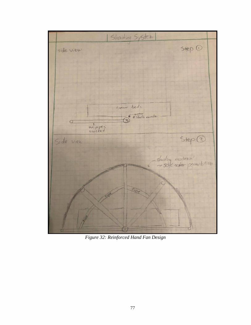
77
Figure 32: Reinforced Hand Fan Design

78
Figure 33: Square Frame Design

79
Appendix B: Shading Structure Hand and FEA Calculations
Figure 34: Horizontal tubing (shaded) with equally distributed weight and resultant
forces from each bolted bracket.
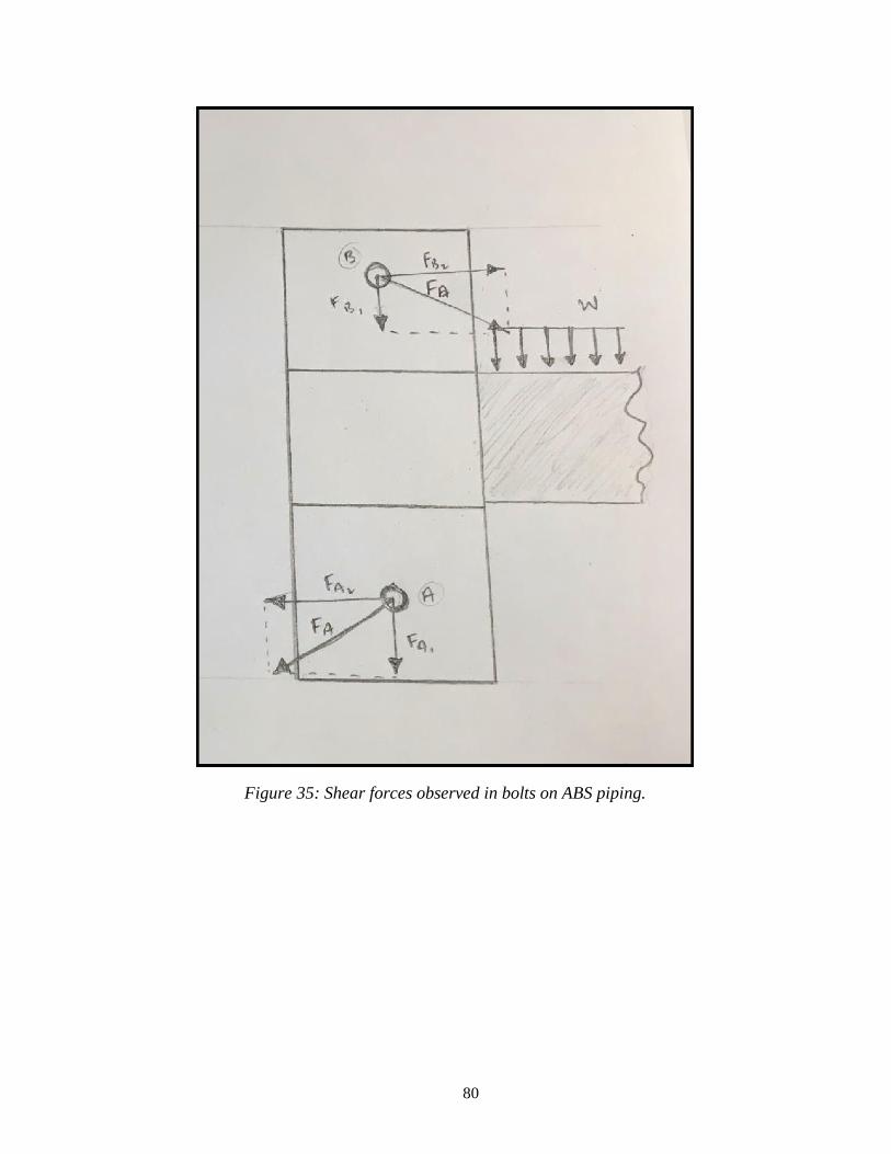
80
Figure 35: Shear forces observed in bolts on ABS piping.

81
Figure B36: Diagram depicting solar load experienced by grow bed and shading structure.
Calculations for the radiative heat transfer seen by the grow beds also included.

82
Figure 37: Hand calculations to determine maximum shear stress and bearing stress in ABS
given load of motor and tubing assembly [25].

83
Figure 38: Calculations to determine the maximum vertical force capable of being withstood by
the solar shade until critical bearing failure occurs in ABS.
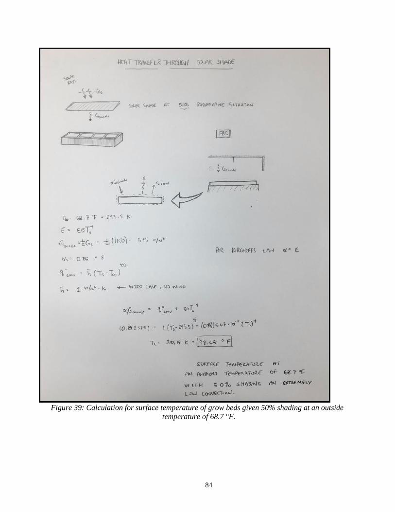
84
Figure 39: Calculation for surface temperature of grow beds given 50% shading at an outside
temperature of 68.7 °F.

85
Figure 40: Styrofoam grow bed surface temperature test (through SolidWorks) with a 50% solar
shade experiencing 74.2°F surface temperature with ambient temperature of 95°F.

86
Appendix C: Pump Selection Calculations
Figure 41: Pump Head Loss Calculation
Spreadsheet.

87
Appendix D: Temperature Data Logging Materials
Figure 42: Arduino code for Node MCU wifi chip.

88
Figure 43: Template of excel spreadsheet for weekly temperature histogram reports.
Figure 44: QR code to access the temperature reading app. Note, users must first
download Blynk on their mobile device before scanning code in the app.

89
Appendix E: Location Photos of LEAP 5 High School
Figure 45: Existing Conditions Photos at LEAP 5 High School in Jane Furse, South
Africa.

90
Figure 46: Bathtubs that will be reused for wicking grow beds.
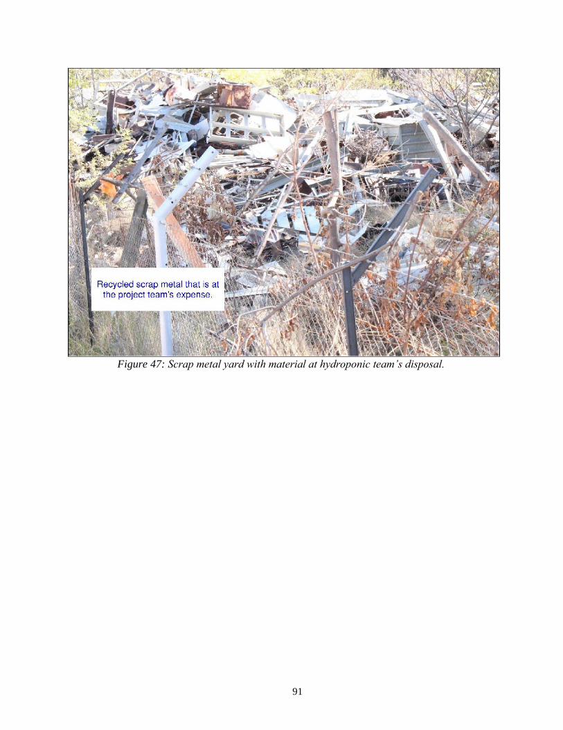
91
Figure 47: Scrap metal yard with material at hydroponic team’s disposal.
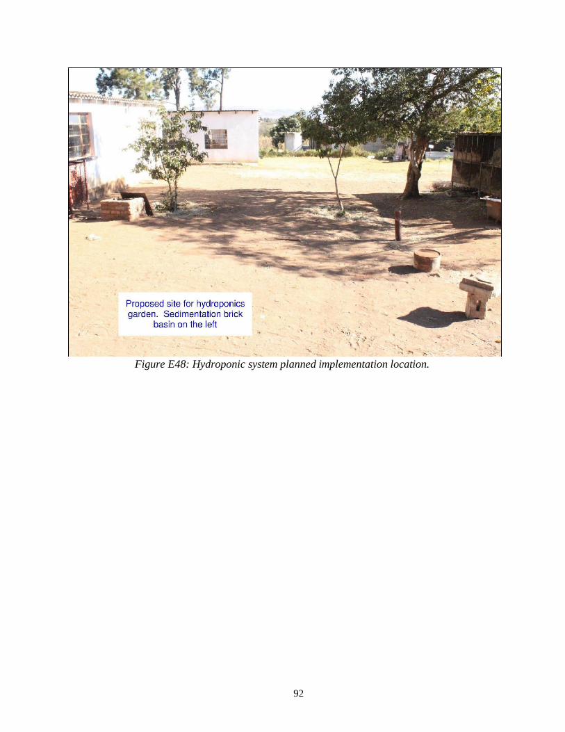
92
Figure E48: Hydroponic system planned implementation location.

93
Figure 49: LEAP 5 greywater catchment system.

94
Figure 50: Location of overflow basin that waters lawn.

95
Appendix F: Greywater Filter Hand Calculations and Design
Figure 51: Hand Calculations for Sizing of Greywater Filter.

96
Figure 52: Preliminary Design of Constructed Wetland Greywater Filter.
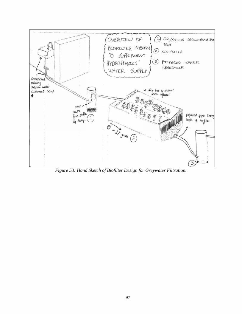
97
Figure 53: Hand Sketch of Biofilter Design for Greywater Filtration.
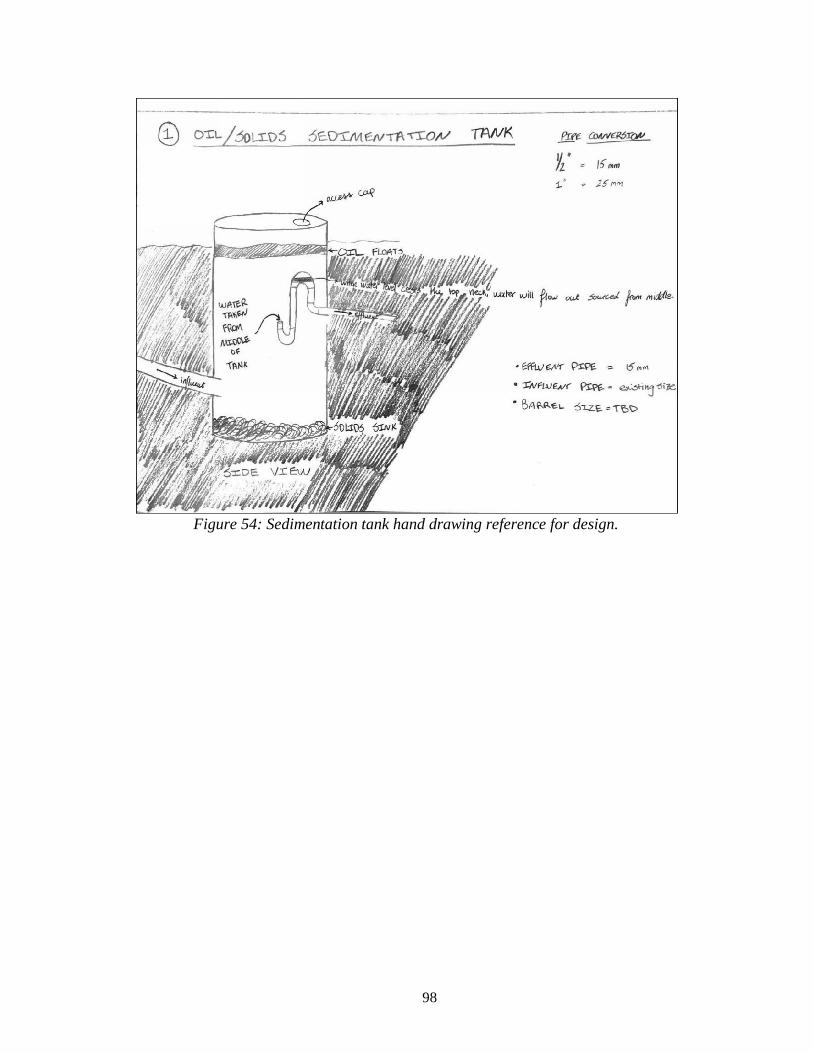
98
Figure 54: Sedimentation tank hand drawing reference for design.

99
Figure 55: Biofilter layers shown as a cross-sectional view.

100
Figure 56: Hand sketch of filtered water reservoir.


![Hydroponics introduction to hydroponics [website capture] ww](https://static.fdocuments.in/doc/165x107/58f9c1f1760da32f4b8b6236/hydroponics-introduction-to-hydroponics-website-capture-ww-58f9c3706c6b1.jpg)