Design of a Gear Box -...
38
Design of a Gear Box Part-III & IV Calculation of Loads on Shaft, Bearing Selection & Shaft Design 1
Transcript of Design of a Gear Box -...
Design of a Gear BoxgPart-III & IV
Calculation of Loads on Shaft, Bearing Selection & Shaft Design
1
A helical gear reduction unit has to
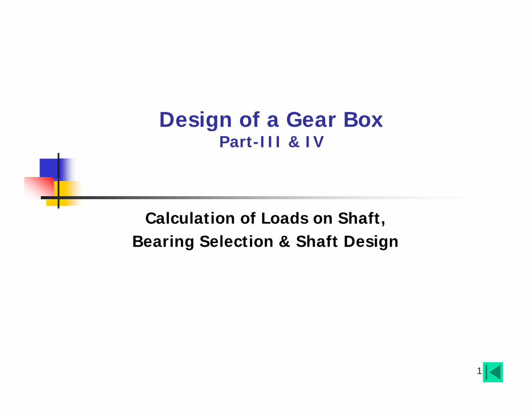
A Typical Helical Gear Box Design Problem (Example) Recapitulation
gtransmit 31 Nm input torque at 1500 rpm with a total reduction of about 37 to 40.
At starting the torque may go as high as g q y g g200% and also there is medium shock loads during operation.
The material for pinion is EN 19A and for Assembled plan view is of 2-stage gear box.pgear wheel it is EN 18A.
The gear box may be an ordinary industrial class unit preferably with p yuncorrected gears.
It is continuous duty with medium shock and overhauling time is Two years.g y
(Alternatively -the bearing life should not be below 10,000 hours). First Stage
2
Photographic plan view is of 2-stage gear box.
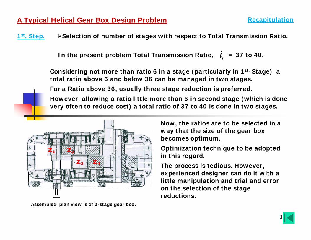
A Typical Helical Gear Box Design Problem Recapitulation
1st. Step. Selection of number of stages with respect to Total Transmission Ratio.
In the present problem Total Transmission Ratio, = 37 to 40.tiConsidering not more than ratio 6 in a stage (particularly in 1st. Stage) a g g (p y g )total ratio above 6 and below 36 can be managed in two stages. For a Ratio above 36, usually three stage reduction is preferred. However, allowing a ratio little more than 6 in second stage (which is done e often to ed ce cost) a total atio of 37 to 40 is done in t o stagesvery often to reduce cost) a total ratio of 37 to 40 is done in two stages.
Now, the ratios are to be selected in a way that the size of the gear box becomes optimum. Optimization technique to be adopted in this regard. The process is tedious HoweverThe process is tedious. However, experienced designer can do it with a little manipulation and trial and error on the selection of the stage reductions
3
reductions.Assembled plan view is of 2-stage gear box.

A Typical Helical Gear Box Design Problem Recapitulation
1st. Step (Contd). Selection of number of stages for a Total Transmission Ratio = 37 to 40i
Considering two stage reduction the numbers of teeth of pinions and gears were selected as follows:
Transmission Ratio = 37 to 40.ti
76.417812
1 ZZi
1st. Stage:
171Z
19.8161314
2 ZZi
2nd. Stage:
163Z
2 4 81 131Z Zi ii
Therefore, total ratio becomes:
Assembled plan view is of 2 stage gear box
2 4
1 3 17 164.76 8.19Z Z
1 2i × i
3 9 . 0 1
ti
4
Assembled plan view is of 2-stage gear box.This is acceptable.

A Typical Helical Gear Box Design Problem Recapitulation
1st. Step (Contd). Selection of number of stages for a Total Transmission Ratio = 37 to 40i
In choosing the numbers of teeth and stage ratios, not only the size optimization is
id d b l h d i
Transmission Ratio = 37 to 40.ti
considered but also the roundness in centre distances with uncorrected gears is taken care* of:
2nd St2nd. Step.
In next step gears are designed as described in earlier lectures.
3Assembled plan view is of 2-stage gear box.
Estimated 1st. Stage module is 1 3nm mm
2 4nm mmand 2nd. Stage module is
i h i bl l i f h li l f hi h11 26 52o With a suitable selection of helix angle, , for which and centre distances become:
1 2 11 26 52o
1 2cos cos 0.98
*1 2 11
(17 810 98 0
( ) 3 3 1502 9
) 98
82 2
nZ Z mA mm
5
11 0.98 0.2 c 98os 2 2
*3 4 22
2
(16 1310.
( ) 14) 4 4 3002 co 98 0.92
7s 82
nZ Z mA mm
and

Sl. No. DescriptionFirst Stage Second Stage
Pinion Gear Pinion Gear
Gear Data
Pinion Gear Pinion Gear
1. ,, Number of Teeth 17 81 16 131
2. Profile Involute Full Depth, Un corrected
3 Normal module 3 mm 4 mm
Zo20
m3. , Normal module 3 mm 4 mm
4. , Helix Angle
RH LH LH RH5 Addendum Height (mm) = 3 0 4 0
nm
256211 o
f 01
256211 o
5. Addendum Height (mm) = 3.0 4.0
6. Dedendum Height (mm) 3. 75 5.0
7. , Pitch Circle Diameter (PCD) (mm) 52.04 247.96 65.306 534.69
na mf nm0.1
nd mf
d
nm25.1
, ( ) ( )
8. , Addendum or Tip Diameter (mm) 58.04 253.96 73.30 542.70
9. Dedendum or Root Diameter (mm) 44.54 240.46 55.30 524.70
pd
ad
d
10. , Face width. (mm) 63 58 68 63
11. Material EN 19A EN 18A EN 19A EN 18A
12 S f H d (BHN) 350 300 350 300
dd
b
6
12. Surface Hardness (BHN)(Through Hardened)
350 300 350 300
p and g may be added to subscript of Nomenclature to indicate pinion and gear respectively. Similarly 1 and 2 can be added to indicate stage of Gear.

3rd. Step. Layout & Bearing Selection
Layout of pinion and gears is made in next step. Shafts are automatically shaped.
Then Bearing types are chosen taking into account service severity and life.
Taper Roller Bearing to be used in pair.p g pmay be used in pair or in combination.
For an example both spherical roller and
Other Bearings-
Distance between Bearing(Taper Roller) supports.
p pball bearing can be combined with cylindrical roller bearing in the other end.
Choice depends on type of loading mainly.
Spherical Roller
p yp g y
Locking of bearings with shaft and housing is to be decided at this stage.
h i f i l d b b iSpherical RollerBearing Sharing of reaction loads by bearings
depends also on of bearing Locking arrangement.
7Cylindrical RollerBearing
Ball Bearing(Deep Groove)
With distance between bearing supports the shaft is considered as “simply supported beam”.

Layout of a single stage Gear Box
Layout & Bearing Selection (Contd…..)3rd. Step:
β
Plan View -Schematic
8

Layout & Bearing Selection (Contd…..)3rd. Step:
Roller Bearings:
(Not taper roller in this case)
Assembled plan view of a 2-stage gear box.
in this case).
C id i
10 to 15 mm (Typical)15 to 25 mm (Typical)
15 to 25 mm (Typical)
Considering bearing widths,
5053
1 8
10 to 15 mm (Typical) (Typical)( yp )
finally distances are marked
Layout of Intermediate Shaft (Referring to Example Problem) 9
178 are marked.

Layout & Bearing Selection (Contd…..)3rd. Step:
Z1
Z
Z3 Z4
Z2
Assembled plan view (Top cover removed)
Layout of Intermediate Shaft (Referring to Design Problem)10

4th. Step. Loads on Gear, Pinion Teeth (Helical Gear).2
tp
TFd
Tangential Load:
pd
tt
FF Normal Load:
cosn
pZ md
cossec .sectn
nn t nF FF
costnFNormal Load:
n
tFtF
n
r n nF = F .sinαF β i
Radial Load:
ntantF
sec . tan( tan )r t nF F
F
t n n= F secβ.secα .sinα
pd( tan )tF
sin tana n tFF F Axial Load:Forces on Helical Spur Gear Tooth.
11
sa n t
sec .secn t nF F
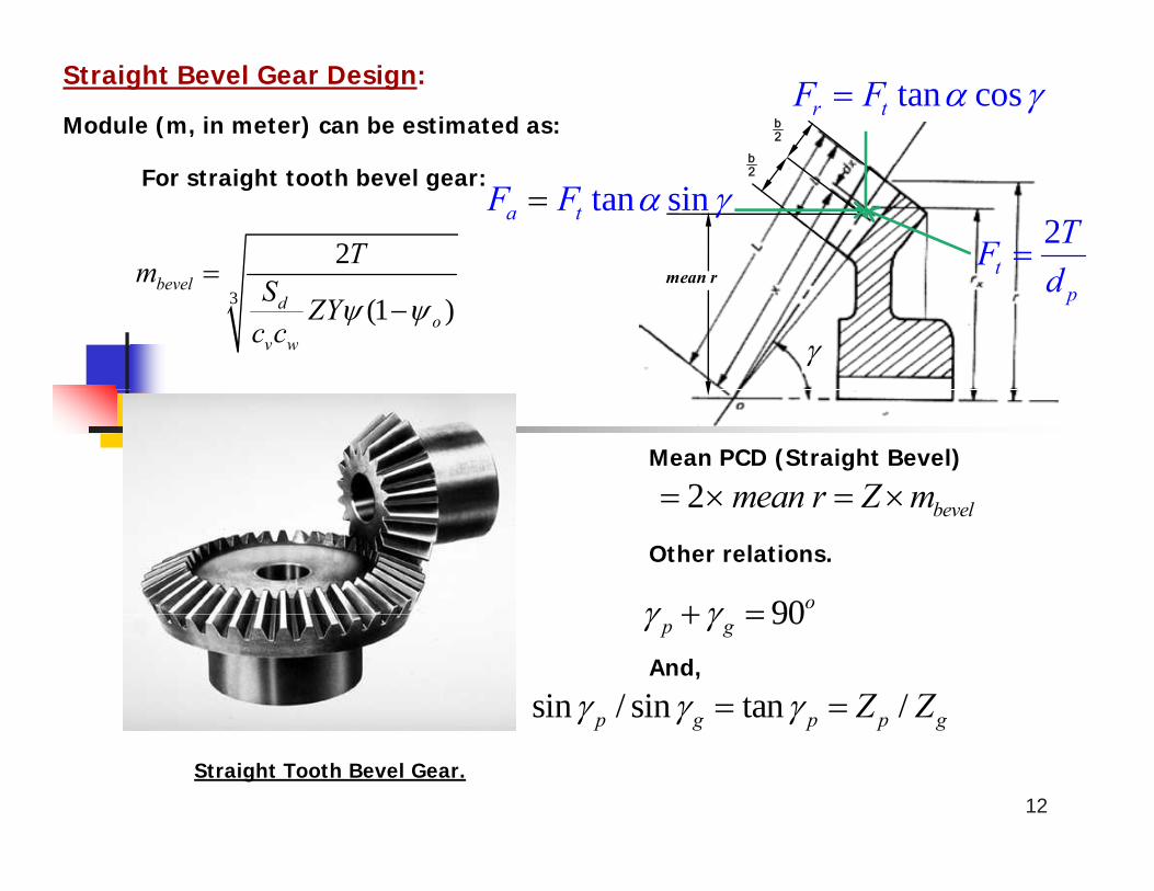
Straight Bevel Gear Design:
Module (m, in meter) can be estimated as:b
b2
tan cosr tF F
2Tm
For straight tooth bevel gear:
mean r
2
2t
TFd
tan sina tF F
3 (1 )bevel
do
v w
m S ZYc c
mean rpd
Mean PCD (Straight Bevel)
2 mean r Z m 2 bevelmean r Z m
90o
Other relations.
90p g
sin / sin tan /p g p p gZ Z And,
12
Straight Tooth Bevel Gear.
p g p p g

For Intermediate Shaft (Referring to Design Problem)
Nominal Torque Input Torque x RatioTorque ( ) Flow Path2nT
Calculation of Loads and Reactions on Shaft & Bearing4th. Step (Contd…):
22 1
1
31 4.76 148n nZT T NmZ
Nominal Torque = Input Torque x Ratio
2Z (81)
pcd 248 mm
Torque ( ) Flow Path
5053
3Z (16)pcd 65.3 mm
n2= 2 × T / 0.248 N = 1193.5 Nt2F
= F secβ tanαF5053
178Intermediate Shaft with gears and Bearings
t2 1 no o
F secβ .tanα= 1193.5 × sec(11 26 52 )× tan(20 )= 1193.5 1.02 0.364 =
r2F
443 NIntermediate Shaft with gears and Bearings
3rF F F
t2 1o
= F tanβ= 1193.5 × tan(11 26 52 )=
a2F
240 65 N3aF a2F
3tF 2tF 2rF
= 240.65 N
Similarly forces (rounded of) at pinion ( ) of 2nd. Stage:
3Z
F F13
Applied Loads, Reactions & Moments due to Axial Loadst3F = 4533 N r3F =1683 N
a3F = 914 N

For Intermediate Shaft (Referring to Design Problem)
Loads and reactions are calculated on theTorque ( ) Flow Path2nT
Calculation of Loads and Reactions on Shaft & Bearing4th. Step (Contd…):
Loads and reactions are calculated on the basis of Nominal Torque & approximate bearing width = 25 mm.
2Z (81)pcd 248 mm
o que ( ) o at
RLBending Moment due to Axial Load:
22 2
240.65 0.2479 302 2p
a a
dM F Nm
914 0 0653d 5053
3Z (16)
pcd 65.3 mm
g
R 3F
33 3
914 0.0653 302 2p
a a
dM F Nm
Intermediate Shaft with gears and Bearings
178
For moment equilibrium (horizontal plane) about R
VLR
HLRVRR
HRR
3rF3aF 2aF
3tF 2tF 2rF
1683 0.125 443 0.05 30 300.178 0.178 0.178 0.178
1182 124.4 168.5 168.5
HLR
= 720.6 N3t 2t 2r
3aM 2aMFrom force equilibrium- HRR = 520 N
Similarly computing for vertical plane:3F = 4533 N F =1683 N F = 914 N
14
VLR = 3518.5 N VRR =2208 N
Applied Loads, Reactions & Moments due to Axial Loads
t3F = 4533 N r3F =1683 N a3F = 914 N
t2F = 1193.5 N r2F =443 N a2F = 240.65 N

For Intermediate Shaft (Referring to Design Problem)
Torque ( ) Flow Path2nT YFXVFCP
Equivalent Load Acting on bearing is expressed as:
Bearing Life Estimation5th. Step:
2Z (81)
pcd 248 mm
q ( )
R
ar YFXVFCP 1expressed as:
Life of Rolling Element bearing in Number of Revolution is expressed as:
CL
3Z (16)
pcd 65.3 mm
R610
PCLN Revolution
Life in hours is then estimated as: L
L
5053
17860N
HLLN
Hours
Loads from Gear teeth were estimated as: F F 683 F 914 N
VLR VRR3rF
3F 2aF
Intermediate Shaft with gears and Bearings (Plan View)t 3F = 4533 N r 3F =1683 N a 3F = 914 N
t 2F = 1193.5 N r2F =443 N a 2F = 240.65 N
Also, moments due to axial forces were M M 30N
HLR HRR3aF 2a
3tF 2tF 2rFHLR = 720.6 N VLR = 3518.5 N
Finally Bearing reactions (radial) were estimated as:
estimated as: 2 3a aM M 30Nm
15
3aM 2aMApplied Loads, Reactions & Moments due to Axial Loads
HL
HRR = 520 NVL
VRR =2208 N
Bearing reactions (axial) yet to be estimated.

From details of loading resultant right b i ( di l) ti i l l t d
The Final bearing reactions:Radial reactions are not in same plane.
Bearing Life Estimation5th. Step (Contd…):
bearing (radial) reaction is calculated as:
2 2 2 2VR HRR +R = 2208 +520
r RF
2268.4 NF
not in same plane.
2268.4 NIt is acting at an angle with vertical plane, R
derived as . 1tanR HR VRR R o13.25Bearing Reactions (& Locking)
5053 r RF a NetF
r LF
R R3rF
2 2 2 23518.5 720.6VL HLR R
r LF
3591.5 N
1 o11 57
r LF r RF
Bearing Reactions (& Locking)
o13 25
o11.57
Similarly,
VLR
HLRVRR
HRR
3r
3aF 2aF
3tF 2tF 2rF
1tanL HL VLR R o1 1 . 5 7
aF
o13.25 and,
Resultant axial load may act only on one bearing irrespective of its direction (i.e., direction of shaft rotation)
t3F = 4533 N r3F =1683 N a3F = 914 N
t2F = 1193.5 N r2F =443 N a2F = 240.65 N
direction of shaft rotation).
It depends on bearing locking arrangement.
In this case it is on right bearing which is with less radial load
16Details of loading & Resultant bearing Reactions.
3 2a aF F
aa NetF F
673.35 N
HLR = 720.6 NHRR = 520 N
VLR = 3518.5 N
VRR =2208 N
with less radial load.Net axial load

Consider deep groove ball bearing SKF 6309
Bearing Life Estimation5th. Step (Contd…):
gas both end supports of intermediate shaft:
Equivalent load on left bearing:d=
55.3
mm
left bearing:
1 ( ) ( )
1.5 (1.0 1 3591.5 0)r L a LC XVF YF
Y
LP X = 1& Y = 1.6
5053 F 2255 75NF 3620 N
aF 678 N
F 2268 4NF 3591 5 N
aF = 673.35 N
Bearing
Inner Dia.(d)
Outer Dia.(D)
Width (B)
Corner Radius (r)
Approx.
Basic Load Capacity
DynamicC
StaticC
5387.25 N[Note: is taken as 1.5 considering medium shock load (given) on
1C r RF 2255.75N r LF 3620 N r RF 2268.4N r LF 3591.5 N
ea gNo.
(d) ( ) C Co
mm mm mm mm Newton Newton
6309 45 100 25 2.5 40130 29200
shock load (given) on the estimated load on bearings based on nominal torque.]
3 6( ) (40130 / 5387.5) 1060 (1500 17 / 81) 60
N LLN
H ︵L ︶
L
Life (in hrs) of left bearing:
17
60 (1500 17 / 81) 60N
60.021880 ×10 hrs = 21,880 hrs
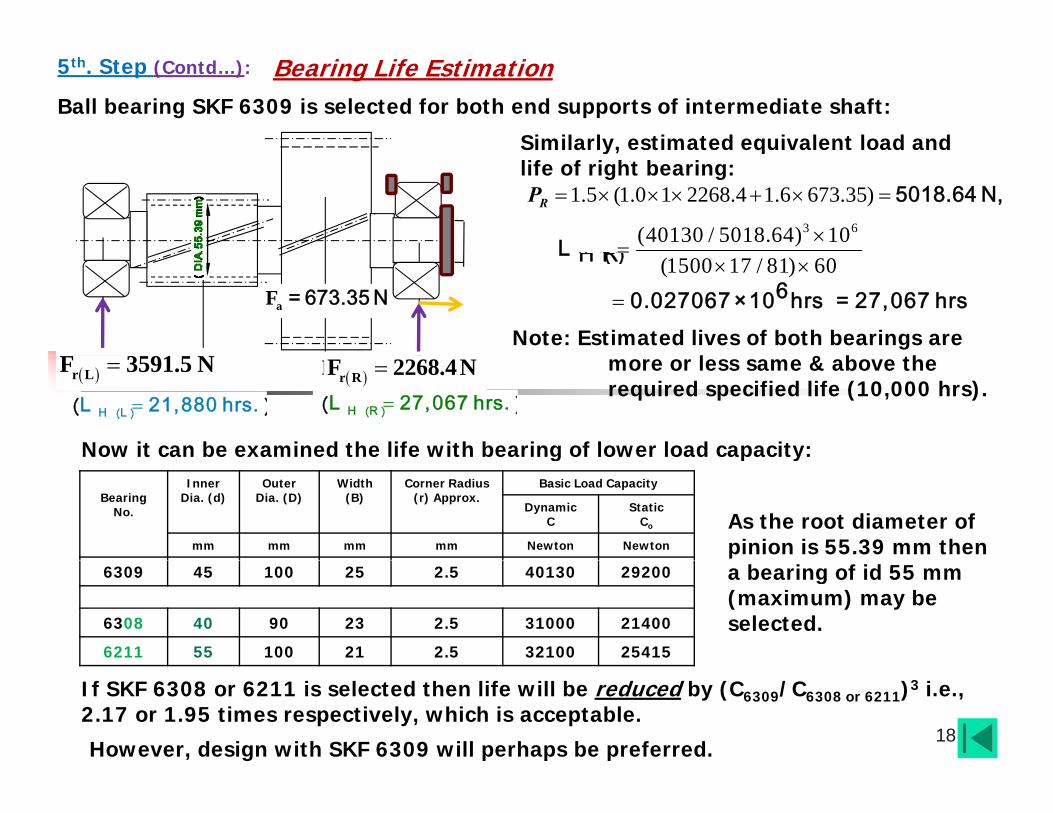
Ball bearing SKF 6309 is selected for both end supports of intermediate shaft:
Similarly, estimated equivalent load and
Bearing Life Estimation5th. Step (Contd…):
y, qlife of right bearing:
1.5 (1.0 1 2268.4 1.6 673.35) 5018.64 N,RP3 6(40130 / 5018.64) 10
H ︵R ︶
L(1500 17 / 81) 60
H ︵R ︶
6
L
0.027067 ×10 hrs = 27,067 hrsNote: Estimated lives of both bearings are
l & b h50533620 N
aF 678 NaF = 673.35 N
H ︵L ︶
L 21,880 h︵ rs. ︶
more or less same & above the required specified life (10,000 hrs).
H ︵R ︶L 27,067 h︵ rs. ︶
Now it can be examined the life with bearing of lower load capacity:
r RF 2255.75 N r LF 3620 N r RF 2268.4N r LF 3591.5 N
Bearing No.
Inner Dia. (d)
Outer Dia. (D)
Width (B)
Corner Radius (r) Approx.
Basic Load Capacity
DynamicC
StaticCo
mm mm mm mm Newton Newton
g p y
As the root diameter of pinion is 55.39 mm then
6309 45 100 25 2.5 40130 29200
6308 40 90 23 2.5 31000 21400
6211 55 100 21 2.5 32100 25415
a bearing of id 55 mm (maximum) may be selected.
18
If SKF 6308 or 6211 is selected then life will be reduced by (C6309/C6308 or 6211)3 i.e., 2.17 or 1.95 times respectively, which is acceptable.
However, design with SKF 6309 will perhaps be preferred.

Specification of Deep Groove Ball Bearing
19

Specification of Taper Roller Bearing
20

Specification of Taper Roller Bearing
21

Specification of Taper Roller Bearing
22

Specification of Spherical Roller Bearing
23

Specification of Cylindrical Roller Bearing
24

Bearing Life Estimation (Contd…)
From details of loading resultant right b i ( di l) ti i l l t d
RecapitulationThe Final bearing reactions:Radial reactions are not in same plane. bearing (radial) reaction is calculated as:
2 2 2 2VR HRR +R = 2208 +520
r RF
2268.4 NF
not in same plane.
2268.4 NIt is acting at an angle with vertical plane, R
derived as . 1tanR HR VRR R o1 3 .2 5Bearing Reactions (& Locking)
5053 r RF a NetF
r LF
R R3rF
2 2 2 23518.5 720.6VL HLR R
r LF
3591.5 N
1 o
r LF r RF
Bearing Reactions (& Locking)
o13 25
o11.57
Similarly,
VLR
HLRVRR
HRR
3r
3aF 2aF
3tF 2tF 2rF
1tanL HL VLR R o1 1 .5 7
aF
o13.25 and,
Resultant axial load may act only on one bearing irrespective of its direction (i.e., direction of shaft rotation)
t3F = 4533 N r3F =1683 N a3F = 914 N
t2F = 1193.5 N r2F =443 N a2F = 240.65 N
direction of shaft rotation).
It depends on bearing locking arrangement.
In this case it is on right bearing which is with less radial load
25Details of loading & Resultant bearing Reactions.
3 2a aF F
aa NetF F
6 73 .35 N
HLR = 720.6 NHRR = 520 N
VLR = 3518.5 N
VRR =2208 N
with less radial load.Net axial load
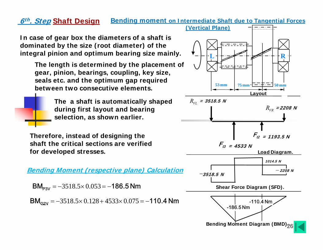
6th. Step Shaft Design Bending moment on Intermediate Shaft due to Tangential Forces (Vertical Plane)
In case of gear box the diameters of a shaft is dominated by the size (root diameter) of the
dominated by the size (root diameter) of the integral pinion and optimum bearing size mainly.
The length is determined by the placement of gear, pinion, bearings, coupling, key size,
l d h i i d
L R
seals etc. and the optimum gap required between two consecutive elements.
The a shaft is automatically shaped during first layout and bearing
53 mm 75 mm 50 mm
Layout
VLR = 3518.5 N
VRR =2208 Nduring first layout and bearing selection, as shown earlier.
Therefore, instead of designing the t2F = 1193.5 N
VRR 2208 N
shaft the critical sections are verified for developed stresses.
Bending Moment (respective plane) Calculation =2208 N
1014.5 N
t3F = 4533 N Load Diagram.
3518.5 0.053 P3VBM 186.5 Nm
3518.5 0.128 4533 0.075 G2VBM 110.4 Nm -110.4 Nm
e d g o e t ( espect e p a e) Ca cu at o
Shear Force Diagram (SFD).
= 3518.5 N
26
G2V
Bending Moment Diagram (BMD).
-186.5 Nm

Shaft Design (Contd…)
Bending Moment (respective plane) Calculation (Contd )
Bending moment on Intermediate Shaft due to Tangential Forces (Horizontal Plane)
plane) Calculation (Contd…)
720 0.053 P3HB M 3 8 .2 N m
L Ra2M
= 30Nma3M30N
Considering from left support Bending Moment just left of section 3-3:
720 0.053P3H-B M 3 8 .2 N m
r3F =1683 N
53 mm 75 mm 50 mm
Layout
= 30Nm
2-23-3
P3H+BM = 68.2 Nm= 38.2 + 30
And just right of section 3-3:
r3
r2F =443 N R = 520 NR = 720 N
P3H+BM 68.2 Nm38.2 30
Similarly, BM just left of section 2-2:
720 0.128 1683 0.075 30 G2H-BM -4 NmHRR = 520 NHLR = 720 N
Load Diagram.
943 N
= 720 N
520 NAnd BM just right of section 2-2:
Shear Force Diagram (SFD).
943 N443 N
68.2Nm26Nm
4.1 30 G2H+BM 26 Nm
27Bending Moment Diagram (BMD).
2-23-3

Second Step: Resultant BendingMoment and Critical Section
6th. Step (Contd….) Shaft Design
L R
79 mm
It is to be noted that in a rotating shaft outer layer experiences maximum flexural bending stress.
53 mm 75 mm 50 mm
Layout2-23-3 3-2
As bending stress is expressed by bending moment divided by section modulus, it is necessary to verify those for probable critical sections.
-186.5Nm-110.4NmIn the Intermediate shaft, any of sections 2-2,
3-2 & 3-3 may be critical i.e., experiences
68.2Nm26N
Bending Moment-Vertical Plane.maximum bending stress.
Bending Moment-Horizontal Plane.
26Nm
2-23-3
28

Next: Resultant Bending Moment and Critical Section (Contd…)
6th. Step (Contd….) Shaft Design
( )
L R
79 mm
Reasons are as follows:
53 mm 75 mm 50 mm
Layout2-23-3 3-2
Among these three sections, through which full torque transmits, section 3-3 has maximum bending moment, although it has also the maximum diameter.
-186.5Nm-110.4Nm
It has medium stress concentration as it is roots of teeth. Sections 2-2 & 3-2 have equal diameters but diff t t t ti f t
68.2Nm26N
Bending Moment-Vertical Plane.different stress concentration factors.At section 3-2 there is step, where as at section 2-2 a there is keyway. Therefore, section 2-2 may be severe than
Bending Moment-Horizontal Plane.
26Nm
2-23-3
Therefore, section 2 2 may be severe than section 3-2 in stress concentration point of view.Again 2-2 usually experiences less BM.
29

Resultant Bending Moment and Critical Section (Contd…) 6th. Step (Contd….) Shaft Design
L RResultant bending moment at 3-3:
79 mm2 268.2 186.5R ︵3-3 ︶BM = = 198.6 Nm
53 mm 75 mm 50 mm
Layout2-23-3 3-2
︵ ︶
2 226 110.4R ︵22 ︶BM = = 113.42 Nm
Resultant bending moment at 2-2:
-186.5Nm
26 110.4R ︵2-2 ︶BM 113.42 Nm
Resultant bending moment at 3-2 is estimated as follows:
-110.4Nm-139.81Nm
68.2Nm26N
Bending Moment-Vertical Plane.
is estimated as follows:
V ︵3-2 ︶
BM = 139.81Nm= 3518.5 0.099 - 4533 0.046
BM 23 92 N720 6 0 099 + 30 1683 0 046
Bending Moment-Horizontal Plane.
26Nm
2-23-3
H ︵3-2 ︶BM = 23.92 Nm= 720.6 0.099 + 30 -1683 0.046
2 223.92 139.81R ︵3-2 ︶BM = = 141.84 Nm
23.92Nm
3-2
30
R ︵32 ︶

Bending Stress and search for Critical Section (Contd…)
6th. Step (Contd….) Shaft Design
L RMaximum bending stress in any section of rotating shaft (solid):
79 mm32My Mf f
d=55
.3 m
m
d=50
mm
53 mm 75 mm 50 mm
Layout2-23-3 3-2
3b c cyf fI d
=
(Section modulus and 4 / 64/ 2
I dy d
-186.5NmMaximum bending stress at section 3-3:
-110.4Nm-139.81Nm
stress concentration factor ).cf
68.2Nm26N
Bending Moment-Vertical Plane.
3
1.5 32 198.60.0553
6
b ︵3-3 ︶
σ = 18×10 Pas
Bending Moment-Horizontal Plane.
26Nm
2-23-3
23.92Nm
3-2
cf is taken 1.5 for hob cut gear.
31

Bending Stress and search forCritical Section (Contd…)
6th. Step (Contd….) Shaft Design
L R
79 mmMaximum bending stress at section 3-2: d=
55.3
mm
d=50
mm
( )
53 mm 75 mm 50 mm
Layout2-23-3 3-2
3
1.5 32 141.840.05
6
b ︵3-2 ︶σ = 17.34×10 Pas
cf is taken 1.5 for well designed step.
-186.5Nm -110.4Nm-139.81NmMaximum bending stress at section 2-2:
68.2Nm26N
Bending Moment-Vertical Plane.
3
2 32 113.420.05
6
b ︵3-2 ︶σ = 18.5×10 Pas
f is taken 2 for milled keyway
Bending Moment-Horizontal Plane.
26Nm
2-23-3
23.92Nm
3-2
cf is taken 2 for milled keyway.
It is apparent that section 2-2 is critical.
32
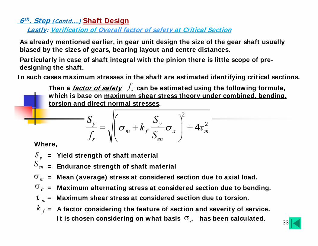
As already mentioned earlier, in gear unit design the size of the gear shaft usually
Lastly: Verification of Overall factor of safety at Critical Section6th. Step (Contd….) Shaft Design
biased by the sizes of gears, bearing layout and centre distances. Particularly in case of shaft integral with the pinion there is little scope of pre-designing the shaft.
In such cases maximum stresses in the shaft are estimated identifying critical sections
Then a factor of safety can be estimated using the following formula, which is base on maximum shear stress theory under combined, bending, torsion and direct normal stresses.
sfIn such cases maximum stresses in the shaft are estimated identifying critical sections.
224y y
m f a ms en
S Sk
f S
s enf
Where,
yS = Yield strength of shaft material
enS = Endurance strength of shaft materialg
m = Mean (average) stress at considered section due to axial load.
a = Maximum alternating stress at considered section due to bending.
m = Maximum shear stress at considered section due to torsion.
33
m
fk = A factor considering the feature of section and severity of service. It is chosen considering on what basis has been calculated. a

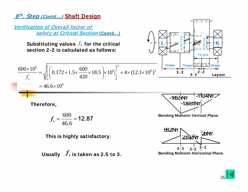
Verification of Overall factor of safety at Critical Section (Contd…)
6th. Step (Contd….) Shaft Design
L R
79 mm
d=55
.3 m
m
d=50
mm
Therefore, for the critical section 2-2:
y ( )
In present design, the pinion is integral with shaft therefore shaft material is EN19A.
53 mm 75 mm 50 mm
Layout2-23-3 3-2
yS = 600 MPa,
enS = 420 MPa (About 45% of for well finished /ground shaft),
uS
-186.5Nm -110.4Nm-139.81Nm
2 2
673.520.05
am c
Ffd
60.172×10 Pas
68.2Nm 26Nm
Bending Moment-Vertical Plane.a 6
b ︵3-2 ︶
σ 18.5×10 Pas
16 16 1482Tf
0.172 10 Pas
Bending Moment-Horizontal Plane.
26Nm
2-23-3
23.92Nm
3-2
f is taken 2 in general for milled single keyway
3 320.05m cf d
61 2 .1× 1 0 P a s
34
cf is taken 2 in general for milled single keyway.
Verification of Overall factor of safety at Critical Section (Contd…)
6th. Step (Contd….) Shaft Design
L R
79 mm
d=55
.3 m
m
d=50
mm
y ( )
Substituting values for the critical section 2-2 is calculated as follows:
Sf
53 mm 75 mm 50 mm
Layout2-23-3 3-2
266 6 2
6
600 10 6000.172 1.5 18.5 10 4 (12.1 10 )420sf
-186.5Nm -110.4Nm-139.81Nm
646.6 10
Therefore,
68.2Nm 26N
Bending Moment-Vertical Plane.60046.6
sf 12.87
Bending Moment-Horizontal Plane.
26Nm
2-23-3
23.92Nm
3-2Usually is taken as 2.5 to 3.sf
This is highly satisfactory.
35
y

Input ShaftThe Input Shaft is also integral with the 1st. stage pinion.
6th. Step (Contd….) Shaft Design
Therefore, the material is EN19A. Shaft design verification is done in same way as it is done for intermediate shaft.
Output ShaftpThe Output Shaft not integral with the gear. Therefore, medium carbon steel (C40 or C45, Equivalent to EN8), having ultimate strength- 560 MPa and yield strength- 280 Mpa, is taken as the
316 o
osa
TdS
material.
The Shaft diameter is initially estimated sa
In the present design considering a factor of 1.5 with nominal torque the Output torque:
on transmitted torque as follows:
1 5 31 39 1T 1818 N1.5 31 39.1oT 1818 NmsaSConsidering allowable shear stress ( ) of material is 60 MPa.
od 53.65 mmNominal
36
Considering the end bearings of ID 55 mm (Say SKF Ball Bearing 6311) Shaft design verification is done same way as is done for intermediate shaft.
o

Design of a Bevel- Helical Two Stage Gear Box:
IMPORTANT:Complete the Gear Design Bearing Selection and Shaft design partComplete the Gear Design, Bearing Selection and Shaft design part
and Complete the full plan view as shown below-
By 14 April, 2017IMPORTANT:Drawing is Individual Task.Use Full sheet.Scale may be 1:1 or 1:2 or 1:2.5Plan the layout to accommodate
Z1
Z2
Z3 Z4
yPlan, elevation and side views in single side of the drawing sheet.A Compensatory class will be held on
Assembled plan view
p y15_04_2017 (Saturday) 8:00 am to 11:00 am In MED Drawing HallThe class test and viva will be held on
37of 2-stage (Bevel-Helical) gear box.(Top cover open)
(Not of the same one as below) 17-04-2017 (Monday)

Thank youThank you
38