Design of A Dowtherm A Pumping · PDF fileDesign of A Dowtherm A Pumping System ......
8
International Journal of Applied Engineering Research ISSN 0973-4562 Volume 11, Number 1 (2016) pp 265-272 © Research India Publications. http://www.ripublication.com 265 Design of A Dowtherm A Pumping System 1 Karthik Silaipillayarputhur, 2 Khalad Al-Muhaysh, 3 Othman Abdullatif Al Yahya 1-3 Department of Mechanical Engineering King Faisal University, Saudi Arabia. Abstract A pumping system from a chemical plant in Chattanooga, TN, USA, is considered in this paper. A pumping system is designed to transfer Dowtherm A (heat transfer fluid) chemical at saturated liquid state, operating at 650°F between two storage tanks. Emphasis is given to pump selection, the various steps in determining the pump specifications, material selection, pipefittings and insulation selection. The importance of net positive suction head (NPSH) calculation is described in the analysis. DuPont Process Safety Management (PSM) Engineering standards are employed in selecting the appropriate materials. A MATLAB model and an Excel model are developed to simulate the required head for various flow rates, pipe dimensions and tank pressures. The steps outlined herein can be used as a reference for designing pumping system for any application. Keywords : Design of Pumping System, Modeling Pumping System Introduction Pumping system is commonly encountered in process industries, power plants, residential units, commercial units, etc. In critical pumping systems, understanding the system and proper equipment and material selection is very important for safe and reliable operation of the system. An improper choice of equipment or material can create a significant safety incident that can harm the environment or mankind. In this project, a pumping system from a chemical plant in Chattanooga is considered. Therein, Dowtherm A, a heat transfer fluid is the pumping medium. Heat transfer fluids are commonly encountered in process plants as they provide very high temperatures at very low pressures as compared to steam. In this work, Dowtherm A chemical at saturated liquid state operating at a temperature of 650°F has to be pumped between two storage tanks. Refer to Figure 1 for details. Herein, emphasis is given to pump selection and to the various steps in determining the pump characteristics. Importance of NPSH calculation is discussed in this study. Occupational Safety and Health Administration (OSHA) standards and DuPont PSM standards are employed in selecting appropriate materials and insulation for the pumping system. Pumps and piping systems have been widely discussed in the literature. Several textbooks and pump manufacturers have described them and only pertinent references are discussed herein. Janna [1] discusses pump and piping systems that includes types of pumps, pump testing methods, piping system design practices, pipe and tubing standards, etc. Tuzson [2] discusses the centrifugal pump design that includes pump specifications, system modeling, pump types, pump configurations, cavitation, performance calculations, system modeling, etc. Jones [3] discusses the design of a pumping station that includes the selection of piping, valves, pump types, pump selection, installation, etc. Chen [4] came up with a single explicit equation for Newtonian fluid correlating the friction factor, pipe roughness, diameter, and Reynolds number for transition and turbulent flow regions that has the same accuracy as that of the implicit Colebrook equation. Engineering Data Book [5] from Hydraulic Institute describes pipe sizes, pressures, relative roughness and friction factors for pipes, the importance of NPSH, etc. DuPont PSM standards [6], a starting point for the OSHA regulations is employed in this project. DuPont PSM standards have been widely accepted and implement across the globe and is considered as one of the best safety standards in the world. The material selection by using the DuPont PSM standards for pipe, fittings, valves, gaskets, insulation, studs and nuts have been discussed in this paper. List of symbols D – Diameter of pipe Ɛ – Pipe roughness f – Friction factor g – Acceleration due to gravity hL – Head loss in piping system; cumulative of major and minor losses K – Loss coefficient for fittings L – Length of piping NPSH – Net positive suction head ΔP – Pressure developed by the pump (Pump discharge pressure – Pump inlet pressure) Re – Reynolds number V – Velocity of flow υ – Kinematic viscosity of the fluid Proposed System Pumping system A pumping system consists of storage tanks, pump(s), piping, fittings (such as elbows, valves, tees, etc.), pipe fittings, pressure gages, relief devices for the tanks, controls etc. Proper design and selection of materials/equipment are required for safe and reliable operation of the pumping system. Consider Figure 1
Transcript of Design of A Dowtherm A Pumping · PDF fileDesign of A Dowtherm A Pumping System ......

International Journal of Applied Engineering Research ISSN 0973-4562 Volume 11, Number 1 (2016) pp 265-272
© Research India Publications. http://www.ripublication.com
265
Design of A Dowtherm A Pumping System
1Karthik Silaipillayarputhur, 2Khalad Al-Muhaysh, 3Othman Abdullatif Al Yahya
1-3Department of Mechanical Engineering
King Faisal University, Saudi Arabia.
Abstract
A pumping system from a chemical plant in Chattanooga, TN,
USA, is considered in this paper. A pumping system is designed
to transfer Dowtherm A (heat transfer fluid) chemical at saturated
liquid state, operating at 650°F between two storage tanks.
Emphasis is given to pump selection, the various steps in
determining the pump specifications, material selection,
pipefittings and insulation selection. The importance of net
positive suction head (NPSH) calculation is described in the analysis. DuPont Process Safety Management (PSM) Engineering
standards are employed in selecting the appropriate materials. A
MATLAB model and an Excel model are developed to simulate
the required head for various flow rates, pipe dimensions and tank
pressures. The steps outlined herein can be used as a reference for
designing pumping system for any application.
Keywords : Design of Pumping System, Modeling Pumping
System
Introduction Pumping system is commonly encountered in process industries,
power plants, residential units, commercial units, etc. In critical
pumping systems, understanding the system and proper
equipment and material selection is very important for safe and
reliable operation of the system. An improper choice of
equipment or material can create a significant safety incident that
can harm the environment or mankind. In this project, a pumping
system from a chemical plant in Chattanooga is considered. Therein, Dowtherm A, a heat transfer fluid is the pumping
medium. Heat transfer fluids are commonly encountered in
process plants as they provide very high temperatures at very low
pressures as compared to steam. In this work, Dowtherm A
chemical at saturated liquid state operating at a temperature of
650°F has to be pumped between two storage tanks. Refer to
Figure 1 for details. Herein, emphasis is given to pump selection
and to the various steps in determining the pump characteristics.
Importance of NPSH calculation is discussed in this study.
Occupational Safety and Health Administration (OSHA)
standards and DuPont PSM standards are employed in selecting appropriate materials and insulation for the pumping system.
Pumps and piping systems have been widely discussed in the
literature. Several textbooks and pump manufacturers have
described them and only pertinent references are discussed herein.
Janna [1] discusses pump and piping systems that includes types
of pumps, pump testing methods, piping system design practices,
pipe and tubing standards, etc. Tuzson [2] discusses the
centrifugal pump design that includes pump specifications,
system modeling, pump types, pump configurations, cavitation,
performance calculations, system modeling, etc. Jones
[3] discusses the design of a pumping station that
includes the selection of piping, valves, pump types,
pump selection, installation, etc. Chen [4] came up with
a single explicit equation for Newtonian fluid
correlating the friction factor, pipe roughness, diameter,
and Reynolds number for transition and turbulent flow
regions that has the same accuracy as that of the implicit
Colebrook equation. Engineering Data Book [5] from Hydraulic Institute describes pipe sizes, pressures,
relative roughness and friction factors for pipes, the
importance of NPSH, etc. DuPont PSM standards [6], a
starting point for the OSHA regulations is employed in
this project. DuPont PSM standards have been widely
accepted and implement across the globe and is
considered as one of the best safety standards in the
world. The material selection by using the DuPont PSM
standards for pipe, fittings, valves, gaskets, insulation,
studs and nuts have been discussed in this paper.
List of symbols D – Diameter of pipe
Ɛ – Pipe roughness
f – Friction factor
g – Acceleration due to gravity
hL – Head loss in piping system; cumulative of
major
and minor losses
K – Loss coefficient for fittings
L – Length of piping
NPSH – Net positive suction head
ΔP – Pressure developed by the pump
(Pump discharge pressure – Pump inlet
pressure)
Re – Reynolds number
V – Velocity of flow
υ – Kinematic viscosity of the fluid
Proposed System Pumping system
A pumping system consists of storage tanks, pump(s),
piping, fittings (such as elbows, valves, tees, etc.), pipe
fittings, pressure gages, relief devices for the tanks,
controls etc. Proper design and selection of
materials/equipment are required for safe and reliable
operation of the pumping system. Consider Figure 1
International Journal of Applied Engineering Research ISSN 0973-4562 Volume 11, Number 1 (2016) pp 265-272
© Research India Publications. http://www.ripublication.com
266
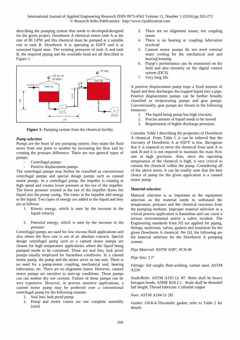
describing the pumping system that needs to developed/designed
for the given project. Dowtherm A chemical enters tank A at the
rate of 80 GPM and this chemical must be pumped at a suitable
rate to tank B. Dowtherm A is operating at 650°F and is at
saturated liquid state. The existing pressures of tank A and tank
B, the required piping and the available head are all described in Figure 1.
Figure 1: Pumping system from the chemical facility
Pump selection
Pumps are the heart of any pumping system; they make the fluid
move from one point to another by increasing the flow and by
creating the pressure difference. There are two general types of
pumps: - Centrifugal pumps
- Positive displacement pumps
The centrifugal pumps may further be classified as conventional
centrifugal pumps and special design pumps such as canned
motor pumps. In a centrifugal pump, the impeller is rotating at
high speed and creates lower pressure at the eye of the impeller.
The lower pressure created at the eye of the impeller draws the
liquid into the pump casing. The vanes in the impeller add energy
to the liquid. Two types of energy are added to the liquid and they
are as follows:
1. Kinetic energy, which is seen by the increase in the liquid velocity
2. Potential energy, which is seen by the increase in the
pressure
Centrifugal pumps are used for low viscous fluid applications and
also where the flow rate is not of an absolute concern. Special
design centrifugal pump such as a canned motor pumps are
chosen for high temperature applications where the liquid being
pumped needs to be contained. These are seal less, leak proof pumps usually employed for hazardous conditions. In a canned
motor pump, the pump and the motor serve as one unit. There is
no need for a pump-motor coupling, mechanical seal, bearing
lubrication, etc. There are no alignment issues. However, canned
motor pumps are sensitive to start-up conditions. These pumps
can run neither dry nor cavitate. Failure of these pumps can be
very expensive. However, in process sensitive applications, a
canned motor pump may be preferred over a conventional
centrifugal pump for the following reasons:
1. Seal less; leak proof pump
2. Pump and motor comes are one complete assembly
(unit)
3. There are no alignment issues; nor coupling
issues
4. There is no bearing or coupling lubrication
involved
5. Canned motor pumps do not need external
water cooling for the mechanical seal and bearing housing
6. Pump’s performance can be monitored on the
field and also remotely on the digital control
system (DCS)
7. Very long life
A positive displacement pump traps a fixed amount of
liquid and then discharges the trapped liquid into a pipe.
Positive displacement pumps can be further broadly
classified as reciprocating pumps and gear pumps.
Conventionally, gear pumps are chosen in the following
instances: 1. The liquid being pump has high viscosity
2. Precise amount of liquid needs to be moved
3. Requirement of higher discharge pressures
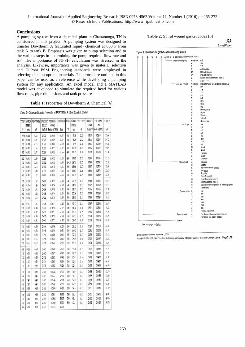
Consider Table I describing the properties of Dowtherm
A chemical. From Table I, it can be inferred that the
viscosity of Dowtherm A at 650°F is low. Recognize
that it is required to move the chemical from tank A to
tank B and it is not required to maintain the mass flow
rate at high precision. Also, since the operating
temperature of the chemical is high, it very critical to contain the chemical within the pump. Considering all
of the above items, it can be readily seen that the best
choice of pump for the given application is a canned
motor pump.
Material selection
Material selection is as important as the equipment
selection as the material needs to withstand the temperature, pressure and the chemical reactions from
the pumping medium. Improper material selection in a
critical process application is hazardous and can cause a
serious environmental and/or a safety incident. The
Engineering standards from [6] are applied for piping,
fittings, studs/nuts, valves, gaskets and insulation for the
given Dowtherm A chemical. Per [6], the following are
the material selection for the Dowtherm A pumping
system:
Pipe Material: ASTM A587, SCH 40
Pipe Size: 2.5”
Fittings: Std weight, Butt-welding, carbon steel, ASTM A234
Studs/Bolts: ASTM A193 Gr B7. Bolts shall be heavy
hexagon heads, ASME B18.2.1. Studs shall be threaded full length. Thread lubricant: Colloidal copper
Nuts: ASTM A194 Gr 2H
Gasket: G63G4 Flexattalic gasket, refer to Table 2 for
details
International Journal of Applied Engineering Research ISSN 0973-4562 Volume 11, Number 1 (2016) pp 265-272
© Research India Publications. http://www.ripublication.com
267
Flanges: Welding Neck; Class 300 forged steel, ASTM A105,
ASME B16.5
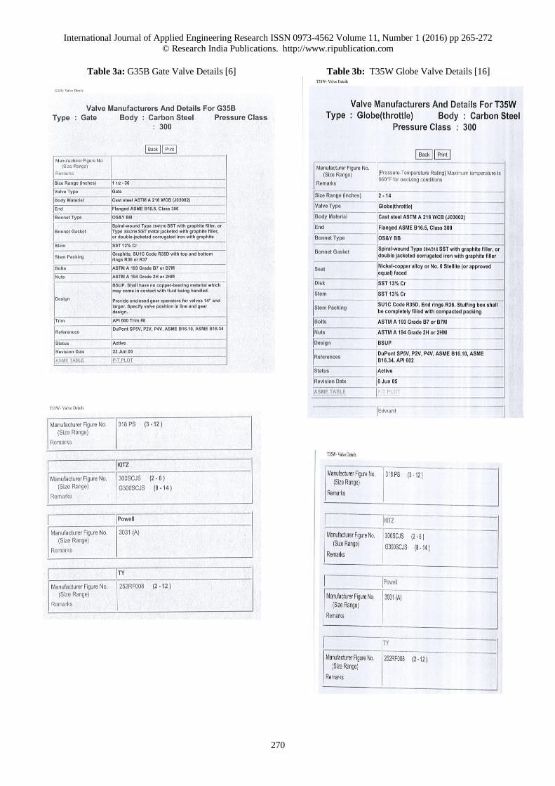
Valves: G35B Flanged gate valve; T35W Flanged globe valve,
refer to Table 3 for details
Insulation: 2” insulation; Type B inside cover (material: Two ply glass cloth with a triple aluminum foil laminate) and Type T
outside cover (material: High temperature Teflon coated glass
cloth, code 746.2)
NPSH (Net positive suction head) calculations
Calculation of NPSH is one of the very basic calculation an engineer/designer needs to perform while designing a pumping
system. The available NPSH would indicate whether a selected
pump would cavitate under the given conditions. The available
NPSH or NPSH(A) is given as follows:
NPSH(A) = Inlet pump pressure – vapor pressure of the fluid
being pumped (1)
The inlet pressure is the summation of the available tank A
pressure and the head pressure at the pump’s inlet. Thus:
Inlet pump pressure = Tank A pressure + available head at the
pump’s inlet (2)
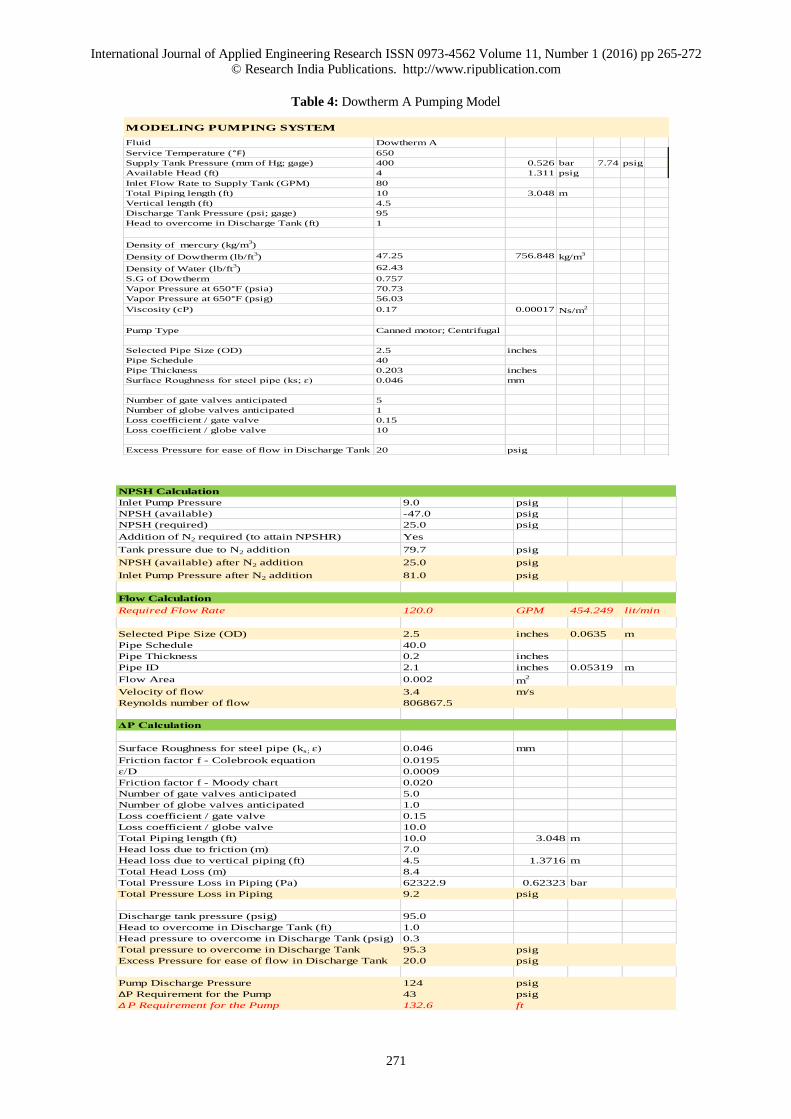
The vapor pressure of the fluid is described in Table 1. Upon calculation for the given conditions, as described in Table 4, it
can be clearly seen that the available NPSH is negative. This
means that the saturated Dowtherm A liquid shall flash off super
heated vapor at the pump’s inlet. Since pumps are not designed to
handle vapor, the pump will most certainly cavitate. In-addition, it
must be noted that the centrifugal pumps are designed such that
the fluid is drawn into the pump by the virtue of low pressure
created at the eye of the impeller. Thus, to compensate for the low
pressure created at the eye of the impeller, the manufacturers of
canned motor pumps usually demand a NPSH(A) of at least 25
psig at the pump’s inlet. In this project, this can be accomplished by adding Nitrogen gas to tank A. Nitrogen being an inert gas,
doesn’t react with Dowtherm A chemical. Therefore, it is safe to
add Nitrogen to tank A to obtain the required NPSH. It should be
noted that both the tanks A and B are designed for a maximum
tank pressure of 150 psig. Thus, it is important to add a relief
valve to tank A, to protect the tank under accidental high
pressures.
Pump’s size & flow rate calculation
From Figure 1, it can be seen that the inlet flow rate to tank A is
80 GPM (gallons per minute). Per the industry standards, pumps
are usually selected to handle more than the required flow rate. This is typically done to address any future expansions in the
company’s processes. Thus, keeping future in mind, the pump is
sized at 1.5X, which means that the pump shall develop 120
GPM. Since the inlet flow rate to tank A is at 80 GPM, the chosen
pump will run dry and begin to cavitate if it is sized at 120 GPM.
Therefore, to circumvent this issue, a certain amount of fluid
being pumped shall be recirculated back to the same tank.
For continuous process applications, the pump’s size is dictated
by the available piping. However, if modifications are feasible,
such as the current scenario, the pump size is chosen per the
optimum pipe diameter and/or by the best available options. Recognize that the larger the pipe size, the greater would be the
initial cost. On the other hand, the larger the pipe size,
the lower is the operating cost. Therefore, in general,
there exists an optimum diameter that minimizes the
initial cost of the pump, the pipe, and the fittings. This
diameter is termed as the optimum diameter. Several
studies have been reported on the optimum pipe size for a given application and the results are reported through
empirical relations such as in [1] or through tables that
are available on the internet. From [6], the optimum
pipe size required for 120 GPM is 2.5 inches and the
existing inlet and discharge connections were at 3
inches and 2.5 inches respectively. Hence, the existing
piping connections were retained and the pump size
shall be 2.5*3.0 (discharge size*inlet size).
For an optimal suction and for uniform velocity
distribution at the pump’s inlet (fully developed flow), it
is essential to maintain a straight run of pipe of at least
10 times the pipe diameter before the pump’s inlet. For the given application, such an ideal condition is difficult
to accomplish.
Head loss calculation
Determining the head loss in the piping system is an
important aspect in determining the pressure that the
pump needs to develop.
Friction factor can be determined by using
Moody chart or by using Colebrook-White equation [7].
The Colebrook-White equation may be given as
(3)
where Ɛ is the roughness of the pipe and Re is the Reynolds number. Reynolds number based on hydraulic
diameter is given by
(4)
The roughness for steel pipes [7] can be approximated
as 0.046 mm.
The head loss due to friction may be given as [7]
(5)
Where corresponds to the major losses in the piping
system and refers to the losses from
elbows, tees, valves, etc., and these are popularly referred as minor losses.
The total head loss is a summation of major losses,
minor losses, and head loss due to vertical piping. Thus:
Total head loss =
+ Head loss due to vertical piping
(6)
International Journal of Applied Engineering Research ISSN 0973-4562 Volume 11, Number 1 (2016) pp 265-272
© Research India Publications. http://www.ripublication.com
268
Pump ΔP Calculation Pump is specified by its kind, size, the flow and the pressure it
needs to develop. For the given application, a canned motor pump
having a flow rate of 120 GPM is required. In order to determine
the pump’s ΔP, it is necessary to determine the required discharge pressure of the pump.
Required Dis. Pressure of Pump = Total head loss + Total
pressure to overcome in tank B + Excess pressure at tank B inlet
(7)
Thus, the pressure that the pump needs to develop is given as
(ΔP)pump = Required Dis. Pressure of the Pump – Inlet
Pressure to the Pump (8)
Recognize that all calculations have been detailed in Table 4.
Based on calculations, it is seen that the canned motor pump
needs to develop 120 GPM at 133 ft of head.
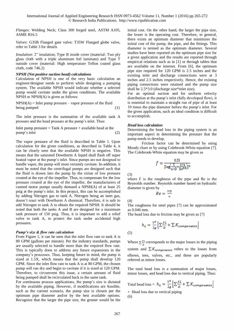
System curve The impact of flow in the piping system can be represented
graphically by means of a system curve. System curve describes
the head required (or the ΔP the pump needs to develop) for
various flow rates. Any pump manufacturer would demand a
system curve from the customer for choosing the right pump for
the given application. The manufacturer would plot the pump
curve on the top of a system curve and the intersection of the two
curves would be the operating point of the pump. It will be hard to choose the right pump in the absence of a system curve. In this
given project, it is desirable to have the operating point
(intersection between the system curve and the pump curve) as
close as possible to the requirement, which is 120 GPM at 133 ft.
of head.
Based on the equations presented a MATLAB model and an
Excel model were developed to study the required head under
various flow rate conditions. Figure 2 describes the system curve
for the given application.
Figure 2: System curve for the project
Final design of the Dowtherm A pumping system As described previously, a pumping system consists of pump,
piping, fittings, insulation, controls, etc. In this project, a 2.5*3.0 canned motor pump is selected to develop a flow rate of 120
GPM at 133 ft of head. It must be recognized that a canned motor
pump is about 3 to 4 times the cost of a regular centrifugal pump;
however, in a canned motor pump, the pumping
medium shall be contained in the event of the pump’s
failure. This aspect is an essential consideration for this
project as the pumping medium is a heat transfer fluid operating at 650°F. The piping, valves, fittings,
insulation are all selected based on [6]. A stand by
pump is also chosen for this project as the second pump
shall serve as a backup in the event of a failure in the
online pump.
It must be noted that both the storage tanks were rated
only for 150 psig and it was essential to pressurize tank A with Nitrogen to have an acceptable NPSH at the
pump’s inlet. Therefore, relief valves were added to the
storage tanks to protect the tanks against any accidental
over pressure. NPSH is a very important concept and is
often ignored or misunderstood in the process industry.
It is very essential to have NPSH(A) greater than
NPSH(R) to protect the pump from cavitation. If
NPSH(A) is lower than NPSH(R), the pumping medium shall flash off super heated vapor at the pump’s inlet,
which would in turn cause the pump to cavitate.
NPSH(R) is provided by the pump manufacturer, and
this parameter is very much a pump specific information
as it takes into account the pressure drop that occurs at
the eye of the impeller.
Though the inlet flow rate to tank A is 80 GPM, keeping future expansions in mind, the new pump was chosen to
develop 120 GPM. To prevent the pump from running
dry, a bypass line was constructed to recirculate some
amount of pumped fluid back to the same tank. In
addition, recirculation kept the heat transfer fluid stirred
in the tank at all times and therefore reduced the
chances of scale formation in the tank walls. A control
valve was chosen such that the level in tank B is maintained at safe limits at all times. In-addition, the
control vale output was adjusted such that the tank A’s
pump did not starve for fluid at any given time.
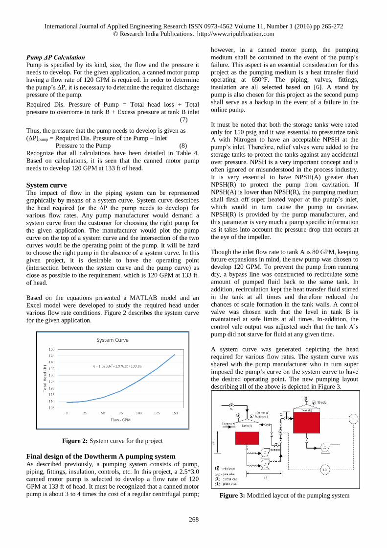
A system curve was generated depicting the head
required for various flow rates. The system curve was
shared with the pump manufacturer who in turn super
imposed the pump’s curve on the system curve to have the desired operating point. The new pumping layout
describing all of the above is depicted in Figure 3.
Figure 3: Modified layout of the pumping system
International Journal of Applied Engineering Research ISSN 0973-4562 Volume 11, Number 1 (2016) pp 265-272
© Research India Publications. http://www.ripublication.com
269
Conclusions A pumping system from a chemical plant in Chattanooga, TN is
considered in this project. A pumping system was designed to
transfer Dowtherm A (saturated liquid) chemical at 650°F from tank A to tank B. Emphasis was given to pump selection and to
the various steps in determining the pump required flow rate and
ΔP. The importance of NPSH calculation was stressed in the
analysis. Likewise, importance was given to material selection
and DuPont PSM Engineering standards were employed in
selecting the appropriate materials. The procedure outlined in this
paper can be used as a reference while developing a pumping
system for any application. An excel model and a MATLAB
model was developed to simulate the required head for various
flow rates, pipe dimensions and tank pressures.
Table 1: Properties of Dowtherm A Chemical [6]
Table 2: Spiral wound gasket codes [6]
International Journal of Applied Engineering Research ISSN 0973-4562 Volume 11, Number 1 (2016) pp 265-272
© Research India Publications. http://www.ripublication.com
270
Table 3a: G35B Gate Valve Details [6]
Table 3b: T35W Globe Valve Details [16]
International Journal of Applied Engineering Research ISSN 0973-4562 Volume 11, Number 1 (2016) pp 265-272
© Research India Publications. http://www.ripublication.com
271
Table 4: Dowtherm A Pumping Model
Fluid Dowtherm A
Service Temperature (°F) 650
Supply Tank Pressure (mm of Hg; gage) 400 0.526 bar 7.74 psig
Available Head (ft) 4 1.311 psig
Inlet Flow Rate to Supply Tank (GPM) 80
Total Piping length (ft) 10 3.048 m
Vertical length (ft) 4.5
Discharge Tank Pressure (psi; gage) 95
Head to overcome in Discharge Tank (ft) 1
Density of mercury (kg/m3)
Density of Dowtherm (lb/ft3) 47.25 756.848 kg/m
3
Density of Water (lb/ft3) 62.43
S.G of Dowtherm 0.757
Vapor Pressure at 650°F (psia) 70.73
Vapor Pressure at 650°F (psig) 56.03
Viscosity (cP) 0.17 0.00017 Ns/m2
Pump Type Canned motor; Centrifugal
Selected Pipe Size (OD) 2.5 inches
Pipe Schedule 40
Pipe Thickness 0.203 inches
Surface Roughness for steel pipe (ks; ɛ) 0.046 mm
Number of gate valves anticipated 5
Number of globe valves anticipated 1
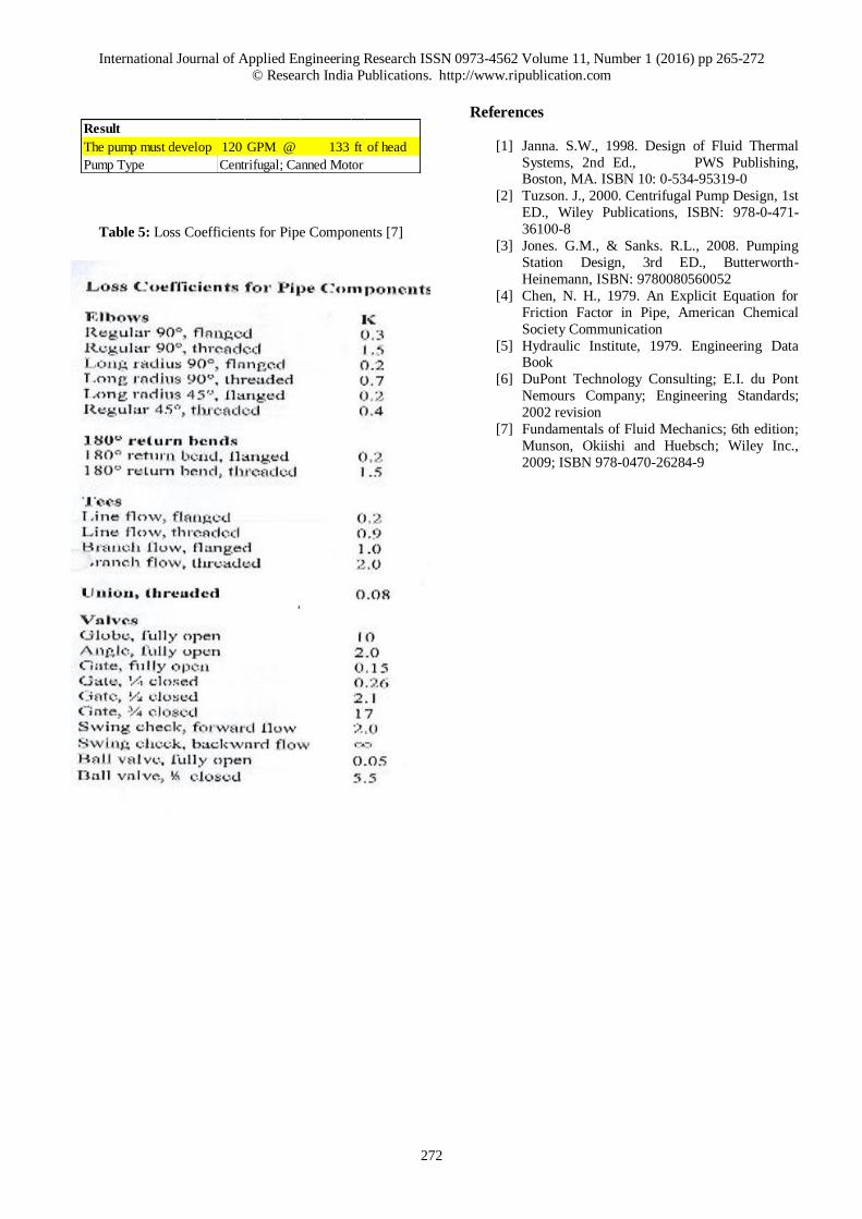
Loss coefficient / gate valve 0.15
Loss coefficient / globe valve 10
Excess Pressure for ease of flow in Discharge Tank 20 psig
MODELING PUMPING SYSTEM
NPSH Calculation
Inlet Pump Pressure 9.0 psig
NPSH (available) -47.0 psig
NPSH (required) 25.0 psig
Addition of N2 required (to attain NPSHR) Yes
Tank pressure due to N2 addition 79.7 psig
NPSH (available) after N2 addition 25.0 psig
Inlet Pump Pressure after N2 addition 81.0 psig
Flow Calculation
Required Flow Rate 120.0 GPM 454.249 lit/min
Selected Pipe Size (OD) 2.5 inches 0.0635 m
Pipe Schedule 40.0
Pipe Thickness 0.2 inches
Pipe ID 2.1 inches 0.05319 m
Flow Area 0.002 m2
Velocity of flow 3.4 m/s
Reynolds number of flow 806867.5
ΔP Calculation
Surface Roughness for steel pipe (ks; ɛ) 0.046 mm
Friction factor f - Colebrook equation 0.0195
ɛ/D 0.0009
Friction factor f - Moody chart 0.020
Number of gate valves anticipated 5.0
Number of globe valves anticipated 1.0
Loss coefficient / gate valve 0.15
Loss coefficient / globe valve 10.0
Total Piping length (ft) 10.0 3.048 m
Head loss due to friction (m) 7.0
Head loss due to vertical piping (ft) 4.5 1.3716 m
Total Head Loss (m) 8.4
Total Pressure Loss in Piping (Pa) 62322.9 0.62323 bar
Total Pressure Loss in Piping 9.2 psig
Discharge tank pressure (psig) 95.0
Head to overcome in Discharge Tank (ft) 1.0
Head pressure to overcome in Discharge Tank (psig) 0.3
Total pressure to overcome in Discharge Tank 95.3 psig
Excess Pressure for ease of flow in Discharge Tank 20.0 psig
Pump Discharge Pressure 124 psig
ΔP Requirement for the Pump 43 psig
ΔP Requirement for the Pump 132.6 ft
International Journal of Applied Engineering Research ISSN 0973-4562 Volume 11, Number 1 (2016) pp 265-272
© Research India Publications. http://www.ripublication.com
272
The pump must develop 120 GPM @ 133 ft of head
Pump Type
Result
Centrifugal; Canned Motor
Table 5: Loss Coefficients for Pipe Components [7]
References
[1] Janna. S.W., 1998. Design of Fluid Thermal
Systems, 2nd Ed., PWS Publishing, Boston, MA. ISBN 10: 0-534-95319-0
[2] Tuzson. J., 2000. Centrifugal Pump Design, 1st
ED., Wiley Publications, ISBN: 978-0-471-
36100-8
[3] Jones. G.M., & Sanks. R.L., 2008. Pumping
Station Design, 3rd ED., Butterworth-
Heinemann, ISBN: 9780080560052
[4] Chen, N. H., 1979. An Explicit Equation for
Friction Factor in Pipe, American Chemical
Society Communication
[5] Hydraulic Institute, 1979. Engineering Data Book
[6] DuPont Technology Consulting; E.I. du Pont
Nemours Company; Engineering Standards;
2002 revision
[7] Fundamentals of Fluid Mechanics; 6th edition;
Munson, Okiishi and Huebsch; Wiley Inc.,
2009; ISBN 978-0470-26284-9