Design of a broadband highly dispersive pure silica ...
6
Design of a broadband highly dispersive pure silica photonic crystal fiber Harish Subbaraman, 1 Tao Ling, 1 YongQiang Jiang, 1 Maggie Y. Chen, 2 Peiyan Cao, 1 and Ray T. Chen 1, * 1 Microelectronic Research Center, Department of Electrical and Computer Engineering, The University of Texas at Austin, Austin, Texas 78758, USA 2 Omega Optics, Incorporated, 10435 Burnet Road, Suite 108, Austin, Texas 78758 *Corresponding author: [email protected] Received 14 November 2006; revised 22 January 2007; accepted 26 January 2007; posted 21 February 2007 (Doc. ID 77069); published 15 May 2007 A highly dispersive dual-concentric-core pure silica photonic crystal fiber is designed with a maximum chromatic dispersion value of about 9500 psnm km around the 1.56 m wavelength region and a full width at half-maximum (FWHM) of 55 nm. The change in the dispersion– bandwidth product as a function of period is carefully studied by using the plane wave expansion method. The coupled mode theory matches well with the plane wave expansion method that was used to simulate the chromatic dispersion. This kind of a photonic crystal fiber structure is suitable for high-dispersion application in phased array antenna systems based on photonic crystal fiber arrays. © 2007 Optical Society of America OCIS code: 060.2280. 1. Introduction In the past decade, there has been an increasing use of lasers operating at 1.55 m in optical com- munication systems. This shift in the operating wavelength from 1.31 to 1.55 m is due to the pres- ence of a low-loss window in silica fibers and due to the invention of erbium-doped fiber amplifiers oper- ating in the same wavelength window [1]. Erbium- doped fiber amplifiers perform an in-line optical amplification of the signal, thus enabling repeater- less transmission for distances greater than a few hundred kilometers. These amplifiers also exhibit ex- cellent noise figures and are compatible with many of the existing components [2]. However, at 1.55 m, the fibers exhibit a chromatic dispersion of about 17 psnmkm [3]. This value is very small for any practical application in true time delay systems. Fibers designed for dispersion compensation in optical communication have shown that very high values of dispersion (D 100 psnmkm) can be achieved in very short lengths of fiber [4]. The dispersion-compensating fibers should have a high negative dispersion coefficient while maintaining minimum losses and low cost. A true time delay unit based on the above mentioned fiber can be used in phased array antenna systems. Since the first working model was demonstrated in the year 1996, photonic crystal fibers [5] (PCFs), fibers with an array of periodic air holes running down the length of the fiber, have gained increasing popularity due to their unique properties such as endless single- mode operation [6], high nonlinearity [7], and ul- tralow loss [8,9]. PCF structures can be designed to have higher negative dispersion values compared with conventional dispersion compensating fibers [10 –12]. These highly dispersive PCFs have a po- tential for high-dispersion applications such as dis- persion compensation to reduce length, payload, and loss [10,13]. Another important application for highly dispersive PCFs is for true time delay ele- ments in phased array antenna systems. This was demonstrated by Jiang et al. [14 –16]. By using PCFs as true time delay elements, the fiber’s total length can be decreased proportionally, leading to compact device structures suitable for airborne and spaceborne applications. Various groups from 0003-6935/07/163263-06$15.00/0 © 2007 Optical Society of America 1 June 2007 Vol. 46, No. 16 APPLIED OPTICS 3263
Transcript of Design of a broadband highly dispersive pure silica ...

Design of a broadband highly dispersive pure silicaphotonic crystal fiber
Harish Subbaraman,1 Tao Ling,1 YongQiang Jiang,1 Maggie Y. Chen,2 Peiyan Cao,1
and Ray T. Chen1,*1Microelectronic Research Center, Department of Electrical and Computer Engineering, The University of Texas at Austin,
Austin, Texas 78758, USA2Omega Optics, Incorporated, 10435 Burnet Road, Suite 108, Austin, Texas 78758
*Corresponding author: [email protected]
Received 14 November 2006; revised 22 January 2007; accepted 26 January 2007;posted 21 February 2007 (Doc. ID 77069); published 15 May 2007
A highly dispersive dual-concentric-core pure silica photonic crystal fiber is designed with a maximumchromatic dispersion value of about �9500 ps��nm km� around the 1.56 �m wavelength region and a fullwidth at half-maximum (FWHM) of 55 nm. The change in the dispersion–bandwidth product as afunction of period is carefully studied by using the plane wave expansion method. The coupled modetheory matches well with the plane wave expansion method that was used to simulate the chromaticdispersion. This kind of a photonic crystal fiber structure is suitable for high-dispersion application inphased array antenna systems based on photonic crystal fiber arrays. © 2007 Optical Society of America
OCIS code: 060.2280.
1. Introduction
In the past decade, there has been an increasing useof lasers operating at � � 1.55 �m in optical com-munication systems. This shift in the operatingwavelength from 1.31 to 1.55 �m is due to the pres-ence of a low-loss window in silica fibers and due tothe invention of erbium-doped fiber amplifiers oper-ating in the same wavelength window [1]. Erbium-doped fiber amplifiers perform an in-line opticalamplification of the signal, thus enabling repeater-less transmission for distances greater than a fewhundred kilometers. These amplifiers also exhibit ex-cellent noise figures and are compatible with many ofthe existing components [2]. However, at 1.55 �m,the fibers exhibit a chromatic dispersion of about17 ps�nm�km [3]. This value is very small for anypractical application in true time delay systems.
Fibers designed for dispersion compensation inoptical communication have shown that very highvalues of dispersion (D � �100 ps�nm�km) can beachieved in very short lengths of fiber [4]. The
dispersion-compensating fibers should have a highnegative dispersion coefficient while maintainingminimum losses and low cost. A true time delayunit based on the above mentioned fiber can be usedin phased array antenna systems. Since the firstworking model was demonstrated in the year 1996,photonic crystal fibers [5] (PCFs), fibers with anarray of periodic air holes running down the lengthof the fiber, have gained increasing popularity dueto their unique properties such as endless single-mode operation [6], high nonlinearity [7], and ul-tralow loss [8,9]. PCF structures can be designed tohave higher negative dispersion values comparedwith conventional dispersion compensating fibers[10–12]. These highly dispersive PCFs have a po-tential for high-dispersion applications such as dis-persion compensation to reduce length, payload,and loss [10,13]. Another important application forhighly dispersive PCFs is for true time delay ele-ments in phased array antenna systems. This wasdemonstrated by Jiang et al. [14–16]. By usingPCFs as true time delay elements, the fiber’s totallength can be decreased proportionally, leading tocompact device structures suitable for airborneand spaceborne applications. Various groups from
0003-6935/07/163263-06$15.00/0© 2007 Optical Society of America
1 June 2007 � Vol. 46, No. 16 � APPLIED OPTICS 3263

all over the world have been working on tweakingthe peculiar properties of PCFs to achieve highnegative dispersion coefficients [10,12] and low-lossstructures. Although most of the methods have beenable to achieve very high negative dispersion values,the bandwidth is strictly limited, resulting in arelatively small dispersion–bandwidth product. Wepresent the design for a dual-concentric-core PCF[17] to achieve a very high negative dispersion coef-ficient of about �9500 ps�nm�km, with a full widthat half-maximum of 55 nm. A cross section of thedesigned fiber is shown in Fig. 1; d1, d2 denote thediameters of the first and second air-hole rings, whichform the inner cladding; d3 denotes the diameter ofthe third air-hole ring, which forms the second core.The rest of the air-hole rings (fourth–tenth rings)form the outer cladding region. The period of the airholes is given by �. The area at the center, deter-mined by the first air-hole ring diameter and theperiod, forms the center core. The research presentedherein has the highest value dispersion–bandwidthproduct reported thus far to our knowledge. It alsohas a high dispersion value that is an improvementby a factor of 5 over previous designs [17] and is apromising candidate for applications requiring com-pact systems for broadband phased array antennas.
2. Theory and Design of a Dual-Concentric-Core PCF
The mechanism of a dual concentric-core PCF is sim-ilar to that of a directional coupler [18]. First, we in-troduce the coupled mode theory for dual-core PCFs[12]. The central core and the outer core behave as twoparallel waveguides, and the high dispersion is fromthe coupling between the two waveguides. By expand-ing the propagation constants, �, of the modes in theisolated waveguides around the phase-matched fre-
quency using Taylor’s series, we get [18]
�i��� � ���p� � �� � �p�d�i
d�����p
��� � �p�2
2d2�i
d�2����p
,
(1)
where i � 1, 2 represents the inner and the outerwaveguide, respectively, and �p represents the phase-matched frequency. From the coupled mode theory,we know that coupling of the individual modes cangenerate two supermodes, whose propagation con-stants can be written as [18]
B� �12���1��� � �2���� � ��1��� � �2����2 � 42, (2)
where � is the coupling constant between the twowaveguides. We can insert Eq. (1) into Eq. (2) anddifferentiate the result twice with respect to angularfrequency. Supposing that the two waveguides’
d2�
d�2����p
are all very small numbers (this term is determinedmainly by the material dispersion of waveguide, andso it must be a very small term), we get the group-velocity dispersion as
d2��
d�2 � �1
4�d�1
d��
d�2
d� �2
�� � �p�2
42 �d�1
d��
d�2
d� �2
� 1��3�2
. (3)
The dispersion parameter is normally written as [1]
D � ��
cd2neff
d�2 � �2�c
�2
d2B
d�2 . (4)
Using Eqs. (3) and (4), we get
D � ��
2c�dn1
d��
dn2
d� �2
�2
2
�� � �p�2
�p2 �dn1
d��
dn2
d� �2
� 1��3�2
. (5)
From Eq. (5), we see that the dispersion valuereaches its maximum value when � is equal to �p andis given by
DMax � ��
2c�dn1
d��
dn2
d� �2
. (6)
The FWHM can be derived from Eqs. (5) and (6) as
� � 0.766 2�p
� ��dn1
d��
dn2
d� ��1�. (7)
From Eqs. (6) and (7), we see that the dispersionvalue depends mainly on the coupling constant � and
Fig. 1. (Color online) Cross section of the designed dual concentriccore PCF.
3264 APPLIED OPTICS � Vol. 46, No. 16 � 1 June 2007
the difference of dn�d� between the inner and theouter core. The bandwidth is dependent on the phase-match wavelength ��p�, the coupling constant �, andthe difference of dn�d� between the inner and theouter core.
There is a trade-off between the maximum disper-sion value and the FWHM. If we multiply Eq. (6) byEq. (7), we can get a dispersion–bandwidth productthat is independent of the coupling constant (�). Thisproduct can be defined as a figure of merit for ourstructure:
�DMax �� � 0.766 �p
c �dn1
d��
dn2
d� �. (8)
Equation (8) shows that the product depends on thephase-match wavelength, and we further define
T � �dn1
d��
dn2
d� �,which is the difference of dn�d� between the innerand the outer core. If our interest is around a specif-ic wavelength, say �p � 1.56 �m, then the productjust depends on the value of T. To maximize thedispersion–bandwidth product, we need to increase Tas much as possible.
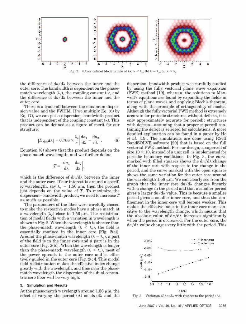
The parameters of the fiber were carefully chosento make the respective modes have a phase match ata wavelength ��P� close to 1.56 �m. The redistribu-tion of modal fields with a variation in wavelength isshown in Fig. 2. When the wavelength is shorter thanthe phase-match wavelength �� � �p�, the field isessentially confined in the inner core [Fig. 2(a)].Around the phase-match wavelength �� � �p�, a partof the field is in the inner core and a part is in theouter core [Fig. 2(b)]. When the wavelength is longerthan the phase-match wavelength �� � �p�, most ofthe power spreads to the outer core and is effec-tively guided in the outer core [Fig. 2(c)]. This modalfield redistribution makes the effective index changegreatly with the wavelength, and thus near the phase-match wavelength the dispersion of the dual concen-tric core fiber will be very high.
3. Simulation and Results
At the phase-match wavelength around 1.56 �m, theeffect of varying the period (�) on dn�d� and the
dispersion–bandwidth product was carefully studiedby using the fully vectorial plane wave expansion(PWE) method [19], wherein, the solutions to Max-well’s equations are found by expanding the fields interms of plane waves and applying Bloch’s theorem,along with the principle of orthogonality of modes.Although the fully vectorial PWE method is extremelyaccurate for periodic structures without defects, it isonly approximately accurate for periodic structureswith defects—assuming that a proper supercell con-taining the defect is selected for calculations. A moredetailed explanation can be found in a paper by Hoet al. [19]. The simulations are done using RSoftBandSOLVE software [20] that is based on the fullvectorial PWE method. For our design, a supercell ofsize 10 10, instead of a unit cell, is implemented forperiodic boundary conditions. In Fig. 3, the curvemarked with filled squares shows the dn�d� changeof the inner core with respect to the change in theperiod, and the curve marked with the open squaresshows the same variation for the outer core aroundthe wavelength 1.56 �m. We can clearly see from thegraph that the inner core dn�d� changes linearlywith a change in the period and that a smaller periodgives a larger dn�d� value. This is because a smallerperiod gives a smaller inner core, and thus the con-finement in the inner core will become weaker. Thismakes the effective index in the inner core more sen-sitive to the wavelength change, which means thatthe absolute value of dn�d� increases significantlywhen the period is decreased. For the outer core, thedn�d� value changes very little with the period. This
Fig. 2. (Color online) Mode profile at (a) � � �p, (b) � � �p, (c) � � �p.
Fig. 3. Variation of dn�d� with respect to the period (�).
1 June 2007 � Vol. 46, No. 16 � APPLIED OPTICS 3265
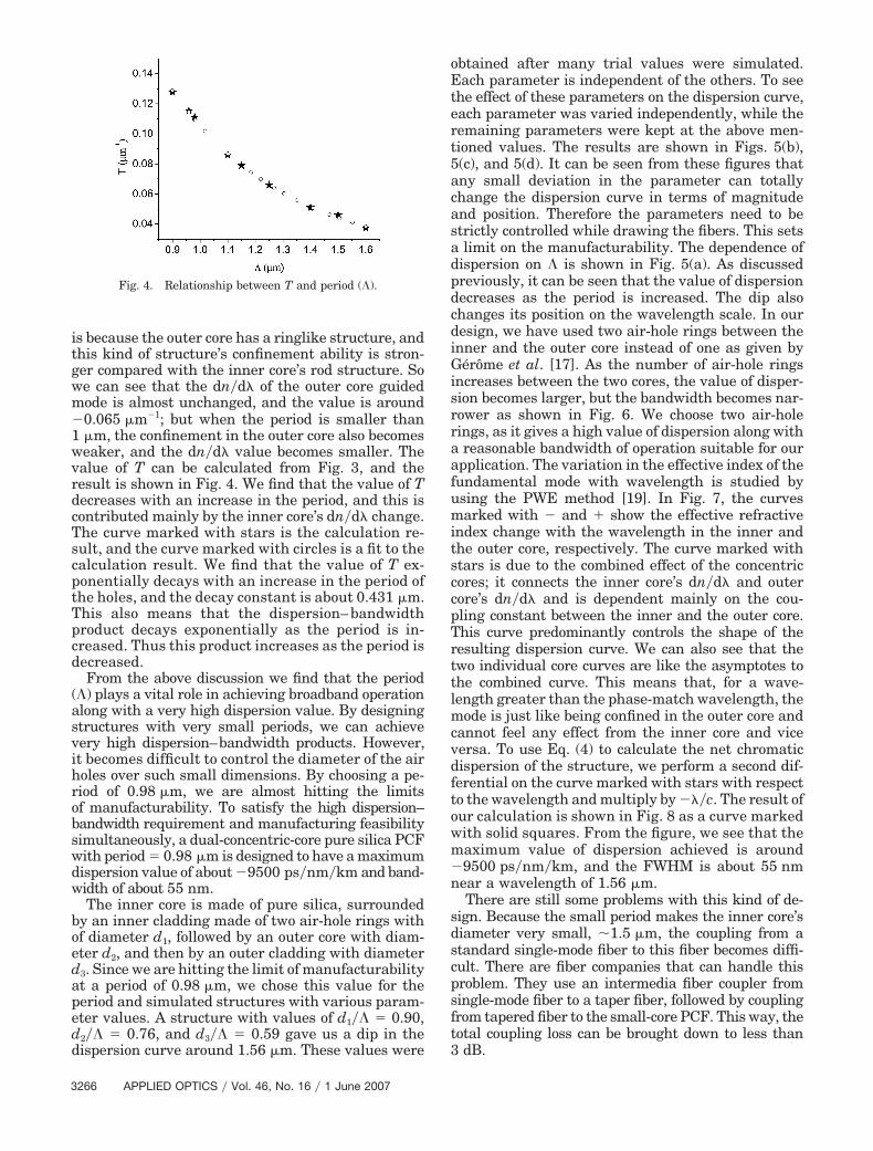
is because the outer core has a ringlike structure, andthis kind of structure’s confinement ability is stron-ger compared with the inner core’s rod structure. Sowe can see that the dn�d� of the outer core guidedmode is almost unchanged, and the value is around�0.065 �m�1; but when the period is smaller than1 �m, the confinement in the outer core also becomesweaker, and the dn�d� value becomes smaller. Thevalue of T can be calculated from Fig. 3, and theresult is shown in Fig. 4. We find that the value of Tdecreases with an increase in the period, and this iscontributed mainly by the inner core’s dn�d� change.The curve marked with stars is the calculation re-sult, and the curve marked with circles is a fit to thecalculation result. We find that the value of T ex-ponentially decays with an increase in the period ofthe holes, and the decay constant is about 0.431 �m.This also means that the dispersion–bandwidthproduct decays exponentially as the period is in-creased. Thus this product increases as the period isdecreased.
From the above discussion we find that the period(�) plays a vital role in achieving broadband operationalong with a very high dispersion value. By designingstructures with very small periods, we can achievevery high dispersion–bandwidth products. However,it becomes difficult to control the diameter of the airholes over such small dimensions. By choosing a pe-riod of 0.98 �m, we are almost hitting the limitsof manufacturability. To satisfy the high dispersion–bandwidth requirement and manufacturing feasibilitysimultaneously, a dual-concentric-core pure silica PCFwith period � 0.98 �m is designed to have a maximumdispersion value of about �9500 ps�nm�km and band-width of about 55 nm.
The inner core is made of pure silica, surroundedby an inner cladding made of two air-hole rings withof diameter d1, followed by an outer core with diam-eter d2, and then by an outer cladding with diameterd3. Since we are hitting the limit of manufacturabilityat a period of 0.98 �m, we chose this value for theperiod and simulated structures with various param-eter values. A structure with values of d1�� � 0.90,d2�� � 0.76, and d3�� � 0.59 gave us a dip in thedispersion curve around 1.56 �m. These values were
obtained after many trial values were simulated.Each parameter is independent of the others. To seethe effect of these parameters on the dispersion curve,each parameter was varied independently, while theremaining parameters were kept at the above men-tioned values. The results are shown in Figs. 5(b),5(c), and 5(d). It can be seen from these figures thatany small deviation in the parameter can totallychange the dispersion curve in terms of magnitudeand position. Therefore the parameters need to bestrictly controlled while drawing the fibers. This setsa limit on the manufacturability. The dependence ofdispersion on � is shown in Fig. 5(a). As discussedpreviously, it can be seen that the value of dispersiondecreases as the period is increased. The dip alsochanges its position on the wavelength scale. In ourdesign, we have used two air-hole rings between theinner and the outer core instead of one as given byGérôme et al. [17]. As the number of air-hole ringsincreases between the two cores, the value of disper-sion becomes larger, but the bandwidth becomes nar-rower as shown in Fig. 6. We choose two air-holerings, as it gives a high value of dispersion along witha reasonable bandwidth of operation suitable for ourapplication. The variation in the effective index of thefundamental mode with wavelength is studied byusing the PWE method [19]. In Fig. 7, the curvesmarked with � and � show the effective refractiveindex change with the wavelength in the inner andthe outer core, respectively. The curve marked withstars is due to the combined effect of the concentriccores; it connects the inner core’s dn�d� and outercore’s dn�d� and is dependent mainly on the cou-pling constant between the inner and the outer core.This curve predominantly controls the shape of theresulting dispersion curve. We can also see that thetwo individual core curves are like the asymptotes tothe combined curve. This means that, for a wave-length greater than the phase-match wavelength, themode is just like being confined in the outer core andcannot feel any effect from the inner core and viceversa. To use Eq. (4) to calculate the net chromaticdispersion of the structure, we perform a second dif-ferential on the curve marked with stars with respectto the wavelength and multiply by ���c. The result ofour calculation is shown in Fig. 8 as a curve markedwith solid squares. From the figure, we see that themaximum value of dispersion achieved is around�9500 ps�nm�km, and the FWHM is about 55 nmnear a wavelength of 1.56 �m.
There are still some problems with this kind of de-sign. Because the small period makes the inner core’sdiameter very small, �1.5 �m, the coupling from astandard single-mode fiber to this fiber becomes diffi-cult. There are fiber companies that can handle thisproblem. They use an intermedia fiber coupler fromsingle-mode fiber to a taper fiber, followed by couplingfrom tapered fiber to the small-core PCF. This way, thetotal coupling loss can be brought down to less than3 dB.
Fig. 4. Relationship between T and period (�).
3266 APPLIED OPTICS � Vol. 46, No. 16 � 1 June 2007

The finite-difference beam propagation method[20–22] (BPM) was used to calculate the two modepatterns in the inner and the outer core, and the
overlap integral method was used to calculate thecoupling constant between the two cores. The simu-lations were done using the RSoft BeamPROP soft-ware package [20]. The software can compute themode patterns, given a refractive index profile andan input field. Apart from calculating the mode pat-terns, this method can also be used to calculate the
Fig. 5. Variation of the dispersion value and the shift observed due to (a) variation in the pitch, (b) variation of d1, (c) variation of d2, and(d) variation of d3, while keeping the other parameters as in the given design in each case.
Fig. 6. Variation of dispersion with number of air-hole rings be-tween the inner and the outer core. Fig. 7. Effect of coupling on the effective refractive index.
1 June 2007 � Vol. 46, No. 16 � APPLIED OPTICS 3267
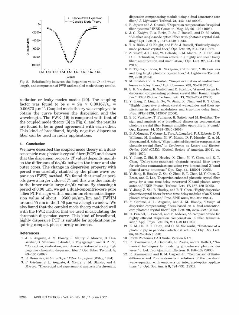
radiation or leaky modes modes [20]. The couplingfactor was found to be � 2� 0.00167��p �0.00673 �m�1. Coupled mode theory was employed toobtain the curve between the dispersion and thewavelength. The PWE [19] is compared with that ofthe coupled mode theory [3] in Fig. 8, and the resultsare found to be in good agreement with each other.This kind of broadband, highly negative dispersionfiber can be used in radar applications.
4. Conclusion
We have described the coupled mode theory in a dual-concentric-core photonic crystal fiber (PCF) and shownthat the dispersion property (T value) depends mainlyon the difference of dn�d� between the inner and theouter cores. The change in dispersion property withperiod was carefully studied by the plane wave ex-pansion (PWE) method. We found that smaller peri-ods gave a larger value of T, and this was due mainlyto the inner core’s large dn�d� value. By choosing aperiod of 0.98 �m, we got a dual-concentric-core puresilica PCF design with a maximum chromatic disper-sion value of about �9500 ps�nm�km and FWHMaround 55 nm in the 1.56 �m wavelength window. Wealso found that the coupled mode theory matched wellwith the PWE method that we used in calculating thechromatic dispersion curve. This kind of broadband,highly dispersive PCF is suitable for applications re-quiring compact phased array antennas.
References1. J. L. Auguste, J. M. Blondy, J. Maury, J. Marcou, B. Dus-
sardier, G. Monnom, R. Jindal, K. Thyagarajan, and B. P. Pal,“Conception, realization, and characterization of a very highnegative chromatic dispersion fiber,” Opt. Fiber Technol. 8,89–105 (2002).
2. E. Desurvire, Erbium-Doped Fiber Amplifiers (Wiley, 1994).3. F. Gérôme, J. L. Auguste, J. Maury, J. M. Blondy, and J.
Marcou, “Theoretical and experimental analysis of a chromatic
dispersion compensating module using a dual concentric corefiber,” J. Lightwave Technol. 24, 442–448 (2006).
4. B. Jopson and A. Gnauck, “Dispersion compensation for opticalfiber systems,” IEEE Commun. Mag. 33, 96–102 (1995).
5. J. C. Knight, T. A. Birks, P. St. J. Russell, and D. M. Atkin,“All-silica single-mode optical fiber with photonic crystal clad-ding,” Opt. Lett. 21, 1547–1549 (1996).
6. T. A. Birks, J. C. Knight, and P. St. J. Russell, “Endlessly single-mode photonic crystal fiber,” Opt. Lett. 22, 961–963 (1997).
7. Z. Yusoff, J. H. Lee, W. Belardi, T. M. Monro, P. C. Teh, andD. J. Richardson, “Raman effects in a highly nonlinear holeyfiber: amplification and modulation,” Opt. Lett. 27, 424–426(2002).
8. K. Tajima, J. Zhou, K. Nakajima, and K. Sato, “Ultralow lossand long length photonic crystal fiber,” J. Lightwave Technol.22, 7–10 (2004).
9. M. Koshib and K. Saitoh, “Simple evaluation of confinementlosses in holey fibers,” Opt. Commun. 253, 95–98 (2005).
10. S. K. Varshney, K. Saitoh, and M. Koshiba, “A novel design fordispersion compensating photonic crystal fiber Raman ampli-fier,” IEEE Photon. Technol. Lett. 17, 2062–2064 (2005).
11. Y. Jiang, T. Ling, L. Gu, W. Jiang, X. Chen, and R. T. Chen,“Highly dispersive photonic crystal waveguides and their ap-plications in optical modulators and true-time delay lines,”Proc. SPIE 6128, 61280Y (2006).
12. S. K. Varshney, T. Fujisawa, K. Saitoh, and M. Koshiba, “De-sign and analysis of a broadband dispersion compensatingphotonic crystal fiber Raman amplifier operating in S-band,”Opt. Express. 14, 3528–3540 (2006).
13. B. J. Mangan, F. Couny, L. Farr, A. Langford, P. J. Roberts, D. P.Williams, M. Banham, M. W. Mason, D. F. Murphy, E. A. M.Brown, and H. Sabert, “Slope-matched dispersion-compensatingphotonic crystal fibre,” in Conference on Lasers and Electro-Optics, 2004 (CLEO) (Optical Society of America, 2004), pp.1069–1070.
14. Y. Jiang, Z. Shi, B. Howley, X. Chen, M. Y. Chen, and R. T.Chen, “Delay-time-enhanced photonic crystal fiber arrayfor wireless communications using two-dimensional X-bandphased-array antennas,” Opt. Eng. 44, 125001 (2005).
15. Y. Jiang, B. Howley, Z. Shi, Q. Zhou, R. T. Chen, M. Y. Chen, G.Brost, and C. Lee, “Dispersion-enhanced photonic crystal fiberarray for a true time-delay structured X-band phased arrayantenna,” IEEE Photon. Technol. Lett. 17, 187–189 (2005).
16. Y. Jiang, Z. Shi, B. Howley, and R. T. Chen, “Highly dispersivephotonic crystal fibers for true-time-delay modules of an X-bandphased array antenna,” Proc. SPIE 5360, 253–258 (2004).
17. F. Gérôme, J. L. Auguste, and J. M. Blondy, “Design ofdispersion-compensating fibers based on a dual-concentric-core photonic crystal fiber,” Opt. Lett. 29, 2725–2727 (2004).
18. U. Peschel, T. Peschel, and F. Lederer, “A compact device forhighly efficient dispersion compensation in fiber transmis-sion,” Appl. Phys. Lett. 67, 2111–2113 (1995).
19. K. M. Ho, C. T. Chan, and C. M. Soukoulis, “Existence of aphotonic gap in periodic dielectric structures,” Phy. Rev. Lett.65, 3152–3155 (1990).
20. RSoft Photonics CAD Suite, Version 5.1.7.21. R. Scarmozzino, A. Gopinath, R. Pregla, and S. Helfert, “Nu-
merical techniques for modeling guided-wave photonic de-vices,” J. Sel. Top. Quantum Electron. 6, 150–162 (2000).
22. R. Scarmozzino and R. M. Osgood, Jr., “Comparison of finite-difference and Fourier-transform solutions of the parabolicwave equation with emphasis on integrated-optics applica-tions,” J. Opt. Soc. Am. A 8, 724–731 (1991).
Fig. 8. Relationship between the dispersion value D and wave-length, and comparison of PWE and coupled mode theory results.
3268 APPLIED OPTICS � Vol. 46, No. 16 � 1 June 2007