Design of a 2.0 MW wind turbine planetary gearbox...Design of a 2.0 MW wind turbine planetary...
317
Design of a 2.0 MW wind turbine planetary gearbox Joana Mˆ eda de Sousa Dissertation submitted to Faculdade de Engenharia da Universidade do Porto for the degree of: Master of Science in Mechanical Engineering Advisor: Prof. Jorge Humberto Seabra (Full Professor) Co-Advisor: Prof. Jos´ e Ant´ onio Almacinha (Assistant Professor) Departamento de Engenharia Mecˆ anica Faculdade de Engenharia da Universidade do Porto Porto, 2017
Transcript of Design of a 2.0 MW wind turbine planetary gearbox...Design of a 2.0 MW wind turbine planetary...
Design of a 2.0 MWwind turbine planetary gearbox
Joana Meda de Sousa
Dissertation submitted toFaculdade de Engenharia da Universidade do Porto
for the degree of:
Master of Science in Mechanical Engineering
Advisor:Prof. Jorge Humberto Seabra
(Full Professor)
Co-Advisor:Prof. Jose Antonio Almacinha
(Assistant Professor)
Departamento de Engenharia MecanicaFaculdade de Engenharia da Universidade do Porto
Porto, 2017
The work presented in this dissertation was performed at theUnit of Tribology, Vibrations and Industrial MaintenanceDepartment of Mechanical EngineeringFaculty of EngineeringUniversity of PortoPorto, Portugal.
Joana Meda de SousaE-mail: [email protected]
Faculdade de Engenharia da Universidade do PortoDepartamento de Engenharia MecanicaUnidade de Tribologia, Vibracoes e Manutencao IndustrialRua Dr. Roberto Frias s/n, Sala M2064200-465 PortoPortugal
Abstract
In recent years there has been much attention to the production of electricity from wind;this is performed by wind turbines. They have been used since ancient times to producemechanical energy with other objectives than producing electricity, like grind grains. Butthe real explosion, in the use of wind turbines to produce electricity, occurred from 1970onwards, when, because of the oil crisis, new ways to produce energy were sought.
A central component in every wind turbine design is the gearbox. Its reliability andcost are critical factors in the success of the overall design. Historically, the wind turbineindustry has been plagued with gearbox failures, which have affected virtually every typeof wind turbine configuration.
Many of these failures can be directly attributed to poor communication between thewind turbine engineer and the gearbox supplier. Successful wind turbine gearbox appli-cations require a close working relationship between these two disciplines, with the activeinvolvement of the wind turbine engineer during the design and procurement process. Thewind turbine engineer must have enough knowledge to specify the application, environ-ment, loads, gear life and quality, acceptance criteria, noise, and many other factors, andrelate this information to the gearbox vendor. Gearbox life expectancy will depend on theability of wind turbine operators to make informed decisions about operation and main-tenance.
The main objective of this dissertation will be the design and dimensioning of a gear-box capable of adapting the low rotations and high torque of the blades of a wind turbineunder conditions of speeds suitable for the generation of energy in the generator. To doso, a research was carried out to evaluate the current state of wind energy production,the type of equipment available, its characteristics and other existing gearboxes. The bestperforming solution was then chosen for optimization. KISSsoft® 2016 and KISSsys®
2016 were used in the dimensioning of gears, shafts, rolling bearings and keys.
Keywords: Planetary gearbox, Power split stage, Wind turbine, Dimensioning, Design,KISSsoft®, KISSsys®, Lubrication, Oil injection.
i

To my friends and family . . .
ii

‘As engrenagens constituem o verdadeiro ex-libris da Engenharia Mecanica’
Professor Paulo Tavares de Castro
iii


Acknowledgements
I would like to thank my supervisor Professor Jorge Seabra and co-advisor Professor JoseAlmacinha, first for offering me the opportunity to perform this project and second, fortheir time devoted to this project, guidance, support, comments and wise remarks.
I am grateful to Professor Paulo Tavares de Castro for the knowledge and unlimitedavailability demonstrated not only during this master thesis but also throughout all thetime I spent at Faculdade de Engenharia da Universidade do Porto. I would like to extendmy thanks to Professor Armando Vilaca de Campos who offered collegial guidance andsupport during my early years of my mechanical engineering graduation.
I could not fail to mention Professor Jose Dias Rodrigues for the encouragement andhelp in the use of appropriate text editing tools that simplified the writing and presenta-tion of this dissertation, as well as, for its essential contribution and mentor ship duringmy graduation.
I wish to express a deep gratitude to the incredible colleagues that I met at CETRIB,for all the inexhaustible help, friendship, support and unforgettable moments in the lastfew months: Joao Sousa e Carlos Pereira. Thanks a lot!
I cannot forget to thank the Faculdade de Engenharia da Universidade do Porto,CETRIB (Unit of Tribology, Vibrations and Industrial Maintenance), LAETA and Sci-Tech for the opportunity and the conditions provided to perform this dissertation.
Last but not the least, my most heartfelt thanks go to my mother and family who havesupported me to perform my master degree and without them I would not be the personI am now.
v


Contents
Abstract i
Acknowledgements v
1 Introduction 1
1.1 Background . . . . . . . . . . . . . . . . . . . . . . . . . . . . . . . . . . . . 1
1.2 Objectives . . . . . . . . . . . . . . . . . . . . . . . . . . . . . . . . . . . . . 2
1.3 Problem definition . . . . . . . . . . . . . . . . . . . . . . . . . . . . . . . . 2
1.4 Layout . . . . . . . . . . . . . . . . . . . . . . . . . . . . . . . . . . . . . . . 3
I 5
2 State of art 7
2.1 Introduction . . . . . . . . . . . . . . . . . . . . . . . . . . . . . . . . . . . . 7
2.2 Brief overview of wind turbine conversion systems . . . . . . . . . . . . . . 7
2.2.1 Global wind power . . . . . . . . . . . . . . . . . . . . . . . . . . . . 7
2.2.2 Development of wind turbine power . . . . . . . . . . . . . . . . . . 9
2.2.3 Costs of wind turbine conversion systems . . . . . . . . . . . . . . . 10
2.3 Wind turbine technology . . . . . . . . . . . . . . . . . . . . . . . . . . . . . 11
2.3.1 Configurations and main components of a wind turbine . . . . . . . 11
2.3.2 Power controls . . . . . . . . . . . . . . . . . . . . . . . . . . . . . . 13
2.4 Gearbox in a wind turbine . . . . . . . . . . . . . . . . . . . . . . . . . . . . 13
2.4.1 Description . . . . . . . . . . . . . . . . . . . . . . . . . . . . . . . . 14
2.4.2 Concepts . . . . . . . . . . . . . . . . . . . . . . . . . . . . . . . . . 15
2.4.3 Market search . . . . . . . . . . . . . . . . . . . . . . . . . . . . . . . 21
II 25
3 Gearbox Design and Dimensioning 27
3.1 Transmission . . . . . . . . . . . . . . . . . . . . . . . . . . . . . . . . . . . 27
3.1.1 Number of transmission stages . . . . . . . . . . . . . . . . . . . . . 27
3.1.2 Shaft arrangement . . . . . . . . . . . . . . . . . . . . . . . . . . . . 28
3.1.2.1 1st Stage . . . . . . . . . . . . . . . . . . . . . . . . . . . . 28
3.1.2.2 2nd and 3rd Stages . . . . . . . . . . . . . . . . . . . . . . 28
3.1.3 Gear type and Helix angle . . . . . . . . . . . . . . . . . . . . . . . . 29
3.1.3.1 1st Stage . . . . . . . . . . . . . . . . . . . . . . . . . . . . 29
3.1.3.2 2nd and 3rd Stages . . . . . . . . . . . . . . . . . . . . . . 30
3.1.4 Module and number of teeth . . . . . . . . . . . . . . . . . . . . . . 30
vii
CONTENTS
3.1.5 Facewidth . . . . . . . . . . . . . . . . . . . . . . . . . . . . . . . . . 32
3.1.6 Profile shift coefficient . . . . . . . . . . . . . . . . . . . . . . . . . . 33
3.1.7 Material selection . . . . . . . . . . . . . . . . . . . . . . . . . . . . . 34
3.1.8 Input and Output conditions . . . . . . . . . . . . . . . . . . . . . . 37
3.1.8.1 General conditions . . . . . . . . . . . . . . . . . . . . . . . 37
3.1.8.2 Operating temperature . . . . . . . . . . . . . . . . . . . . 37
3.1.8.3 Required life time . . . . . . . . . . . . . . . . . . . . . . . 37
3.1.9 Load factors . . . . . . . . . . . . . . . . . . . . . . . . . . . . . . . 38
3.1.9.1 Application factor, KA . . . . . . . . . . . . . . . . . . . . 38
3.1.9.2 Dynamic factor, KV . . . . . . . . . . . . . . . . . . . . . . 38
3.1.9.3 Mesh load factor, Kγ . . . . . . . . . . . . . . . . . . . . . 39
3.1.9.4 Load Distribution Factors, KHα and KHβ . . . . . . . . . . 40
3.1.10 Safety factors . . . . . . . . . . . . . . . . . . . . . . . . . . . . . . . 40
3.1.11 Lubricant and lubricating method . . . . . . . . . . . . . . . . . . . 40
3.1.11.1 Lubricating oil selection . . . . . . . . . . . . . . . . . . . . 40
3.1.11.2 Pressure viscosity parameters . . . . . . . . . . . . . . . . . 43
3.1.11.3 Scuffing and micropitting tests parameters . . . . . . . . . 43
3.1.11.4 Lubricating method selection . . . . . . . . . . . . . . . . . 44
3.1.12 Results . . . . . . . . . . . . . . . . . . . . . . . . . . . . . . . . . . 46
4 Gearbox Optimization 49
4.1 Gears . . . . . . . . . . . . . . . . . . . . . . . . . . . . . . . . . . . . . . . 49
4.1.1 Load spectrum application . . . . . . . . . . . . . . . . . . . . . . . 49
4.1.2 Profile teeth modifications . . . . . . . . . . . . . . . . . . . . . . . . 51
4.1.3 Power split gearbox’s shafts assembly . . . . . . . . . . . . . . . . . 53
4.2 Shafts . . . . . . . . . . . . . . . . . . . . . . . . . . . . . . . . . . . . . . . 59
4.2.1 Assessment of the fatigue strength using nominal stresses: generalsafety factors . . . . . . . . . . . . . . . . . . . . . . . . . . . . . . . 60
4.2.2 Assessment of the fatigue strength using nominal stresses: individualsafety factors . . . . . . . . . . . . . . . . . . . . . . . . . . . . . . . 60
4.2.3 Shaft Results . . . . . . . . . . . . . . . . . . . . . . . . . . . . . . . 61
4.3 Rolling bearings . . . . . . . . . . . . . . . . . . . . . . . . . . . . . . . . . 62
4.4 Spline joints . . . . . . . . . . . . . . . . . . . . . . . . . . . . . . . . . . . . 67
4.5 Housing . . . . . . . . . . . . . . . . . . . . . . . . . . . . . . . . . . . . . . 69
4.6 Other components . . . . . . . . . . . . . . . . . . . . . . . . . . . . . . . . 71
4.6.1 Shaft seals . . . . . . . . . . . . . . . . . . . . . . . . . . . . . . . . . 71
4.6.2 Retaining rings . . . . . . . . . . . . . . . . . . . . . . . . . . . . . . 73
4.6.3 Spacer sleeves . . . . . . . . . . . . . . . . . . . . . . . . . . . . . . . 74
III 77
5 Lubrication system 79
5.1 Introduction . . . . . . . . . . . . . . . . . . . . . . . . . . . . . . . . . . . . 79
5.2 Oil Circulating system conception . . . . . . . . . . . . . . . . . . . . . . . 82
5.2.1 Pipe material selection . . . . . . . . . . . . . . . . . . . . . . . . . . 82
5.2.2 Thread Ports . . . . . . . . . . . . . . . . . . . . . . . . . . . . . . . 83
5.2.3 Pipe End Assembly . . . . . . . . . . . . . . . . . . . . . . . . . . . 84
5.2.4 Pipe diameter selection . . . . . . . . . . . . . . . . . . . . . . . . . 87
5.2.5 Piping design . . . . . . . . . . . . . . . . . . . . . . . . . . . . . . . 91
viii

CONTENTS
IV 95
6 Conclusion and future work 976.1 Conclusions . . . . . . . . . . . . . . . . . . . . . . . . . . . . . . . . . . . . 976.2 Future Work . . . . . . . . . . . . . . . . . . . . . . . . . . . . . . . . . . . 98
References 100
A KISSsoft Reports 105A.1 KISSsoft Reports - Gearing calculation . . . . . . . . . . . . . . . . . . . . . 105
A.1.1 KISSsoft Report - Planetary stage . . . . . . . . . . . . . . . . . . . 107A.1.2 KISSsoft Report - Second stage . . . . . . . . . . . . . . . . . . . . . 123A.1.3 KISSsoft Report - Third stage . . . . . . . . . . . . . . . . . . . . . 137
A.2 KISSsoft Reports - Shaft calculation . . . . . . . . . . . . . . . . . . . . . . 151A.2.1 KISSsoft Report - Planetary coaxial shafts (considering nominal load)153A.2.2 KISSsoft Report - Planet shaft . . . . . . . . . . . . . . . . . . . . . 184A.2.3 KISSsoft Report - Intermediate shaft (superior branch) . . . . . . . 209A.2.4 KISSsoft Report - Intermediate shaft (inferior branch) . . . . . . . . 231A.2.5 KISSsoft Report - High speed shaft (Output) . . . . . . . . . . . . . 257
A.3 KISSsoft Report - Thermal analysis . . . . . . . . . . . . . . . . . . . . . . 283A.3.1 KISSsoft Report - High speed shaft . . . . . . . . . . . . . . . . . . . 285
B Assembly drawing 291
ix

CONTENTS
x

List of Figures
2.1 Profile evolution of cumulative installed capacity worldwide of 2001–2016,[2]. . . . . . . . . . . . . . . . . . . . . . . . . . . . . . . . . . . . . . . . . . 7
2.2 Annual Installed Capacity by Region 2008-2016. Total new wind energycapacity globally installed of 54 642 MW. For a more detailed informationshould be consulted the data source, [2]. . . . . . . . . . . . . . . . . . . . . 8
2.3 EU market shares for new wind energy capacity installed during 2016. Totalof 12 490 MW, [1]. . . . . . . . . . . . . . . . . . . . . . . . . . . . . . . . . 8
2.4 At the left, in the circular chart, share of new installed capacity during2016 (total 24 484 MW). At the right, the cumulative power capacity in theEuropean Union 2005-2016, [1]. . . . . . . . . . . . . . . . . . . . . . . . . . 9
2.5 Evolution of wind turbine size (Ø: rotor diameter; H: tower height). All datacan be founded in different articles, manufactures reports and datasheets,[3–11]. . . . . . . . . . . . . . . . . . . . . . . . . . . . . . . . . . . . . . . . 10
2.6 Leveled cost of energy in United States. U.S. federal tax subsidies remainan important component of the economics of Alternative Energy generationtechnologies (and government incentives are, generally, currently importantin all regions), [12]. . . . . . . . . . . . . . . . . . . . . . . . . . . . . . . . . 10
2.7 Horizontal and vertical axis wind turbines, [3]. . . . . . . . . . . . . . . . . 12
2.8 Transmission ratio i versus the rated turbine speed nrotor, [3]. . . . . . . . . 15
2.9 Three spur wheel stages arrangement, [18]. . . . . . . . . . . . . . . . . . . 16
2.10 One planetary-Two parallel stages gearbox, [18]. . . . . . . . . . . . . . . . 16
2.11 Kinematic diagram of a fixed ring epicyclic gear drive. . . . . . . . . . . . . 16
2.12 Two planetary-One parallel gear stage gearbox, [18]. . . . . . . . . . . . . . 19
2.13 Compound planetary gearbox, [18]. . . . . . . . . . . . . . . . . . . . . . . . 19
2.14 Differential planetary gearbox, [18]. . . . . . . . . . . . . . . . . . . . . . . . 20
2.15 Several gearbox concepts: (a)Planetary gear stage, fixed Planet: RenkAerogear; (b) Hydraulic torque limiting: Henderson Gearbox; (c) PowerSplit, several Generators: Clipper ; (d) Two inputs: Luv and Lee Rotor,Kowintec, [18]. . . . . . . . . . . . . . . . . . . . . . . . . . . . . . . . . . . 20
2.16 Global market share of the world’s leading wind turbine manufacturers in2016, [21]. . . . . . . . . . . . . . . . . . . . . . . . . . . . . . . . . . . . . . 21
3.1 Axial pitch of a helical gear. . . . . . . . . . . . . . . . . . . . . . . . . . . . 29
3.2 Maximum length of the gear meshing line, TT’, [31]. . . . . . . . . . . . . . 31
3.3 Load distribution factor as a function of the number of planet gears, [18]. . 39
3.4 Lubrication methods by Henriot, [42]. . . . . . . . . . . . . . . . . . . . . . 45
4.1 Revolutions distribution. Adapted from a DLC suggested by IEC 61400-4,[34]. . . . . . . . . . . . . . . . . . . . . . . . . . . . . . . . . . . . . . . . . 50
xi

LIST OF FIGURES
4.2 Deformation and meshing interference in loaded, pure involute gear, [43]. . 514.3 Material removal region in a tip relief modification, [43]. . . . . . . . . . . . 524.4 Tip relief on a gear tooth, [43]. . . . . . . . . . . . . . . . . . . . . . . . . . 524.5 Profile diagram of the driving flank. Profile diagram of the driven flank.
Load variation. Hertz pressure profile variation. Tooth mesh. Adaptedfrom Henriot [43] and MAAG [19]. . . . . . . . . . . . . . . . . . . . . . . . 53
4.6 Second and third gearbox stages layout. . . . . . . . . . . . . . . . . . . . . 544.7 Reference positioning of seconf and third gear stages. Both intermediate
pinion and gear are positioned exactly on the same orientation. . . . . . . 554.8 Second and third gearbox stages assembly parameters. . . . . . . . . . . . . 564.9 Curvilinear quadrilateral. . . . . . . . . . . . . . . . . . . . . . . . . . . . . 584.10 Face-to-face tapered roller bearing arrangement and its normal lines. Adapted
from: [49]. . . . . . . . . . . . . . . . . . . . . . . . . . . . . . . . . . . . . . 634.11 Example of spline fits, [55]. . . . . . . . . . . . . . . . . . . . . . . . . . . . 684.12 Radial clearance of a flank fitted spline joint, [54]. . . . . . . . . . . . . . . 694.13 Gear milling toll. Image for illustration only. Final D1 and D2 values will
be supplied with the toolholder. D2=80, [57]. . . . . . . . . . . . . . . . . . 694.14 Tilting angle of main lid (generator side) surface, [57]. . . . . . . . . . . . . 704.15 Radiamatic R35 shaft seal. . . . . . . . . . . . . . . . . . . . . . . . . . . 724.16 Circumferential speed allowed by NBR and FKM SIMRIT® shaft seal ma-
terials. . . . . . . . . . . . . . . . . . . . . . . . . . . . . . . . . . . . . . . 724.17 Shaft seal arrangement. Radiamatic R 35 in combination with a standard
V-ring. . . . . . . . . . . . . . . . . . . . . . . . . . . . . . . . . . . . . . . . 734.18 Retaining ring and spacer washer arrangement. . . . . . . . . . . . . . . . . 744.19 Oil distribution spacer sleeve of a paired single row tapered roller bearing,
[49]. . . . . . . . . . . . . . . . . . . . . . . . . . . . . . . . . . . . . . . . . 744.20 Internal axial clearance of a paired single row tapered roller bearing, [49]. . 75
5.1 SAE / ISO / JIS B2351 Straight Thread Port O-Ring Upon Assembly.Source: Assembly/Installation section of [64]. . . . . . . . . . . . . . . . . . 83
5.2 Tapered Thread Port. Source: Assembly/Installation section of [64]. . . . . 845.3 Sleeve attachment with flanged and brazed assemblies. Adapted from: As-
sembly/Installation section of [64]. . . . . . . . . . . . . . . . . . . . . . . . 845.4 Sleeve attachment with ferrule assemblies. Adapted from: Assembly/Installation
section of [64]. . . . . . . . . . . . . . . . . . . . . . . . . . . . . . . . . . . 855.5 Sleeve attachment with ferrule assemblies. Adapted from: Assembly/Installation
section of [64]. . . . . . . . . . . . . . . . . . . . . . . . . . . . . . . . . . . 855.6 Over-flanging and Under-flanging failures. Source: Assembly/Installation
section of [64]. . . . . . . . . . . . . . . . . . . . . . . . . . . . . . . . . . . 865.7 Estimated housing shape dimensions. . . . . . . . . . . . . . . . . . . . . . . 895.8 Circulating oil desgin. . . . . . . . . . . . . . . . . . . . . . . . . . . . . . . 93
xii

List of Tables
2.1 Cost breakdown of a typical wind turbine, [13]. . . . . . . . . . . . . . . . . 11
2.2 Possible number of planets in relation to the gear ratio Zring/Zsun, [19]. . . 18
2.3 Top manufactures wind turbine characteristics, [22; 23]. . . . . . . . . . . . 22
2.4 Detailed ZF Friedrichshafen gearbox information and parameters, [25]. . . . 22
2.5 Detailed GAMESA gearbox information and parameters, [23]. . . . . . . . . 23
3.1 Number of teeth and module of final gearbox parameters. . . . . . . . . . . 32
3.2 Facewidth, axial pitch and respective ratio of final gearbox parameters. . . 33
3.3 Profile shift coefficient of each gear pair of final gearbox parameters. . . . . 34
3.4 Superficial hardening processes according to gear module value, [19]. . . . . 35
3.5 42 CrMo 4 (DIN) mechanical properties, [33]. . . . . . . . . . . . . . . . . . 36
3.6 18 CrNiMo 7-6 (DIN) mechanical properties, [33]. . . . . . . . . . . . . . . . 36
3.7 Recommended gear tooth surface roughness, [34]. . . . . . . . . . . . . . . . 36
3.8 Assignment of operational behavior to application factor. Adapted fromthe KISSsof® software instructions. . . . . . . . . . . . . . . . . . . . . . . 38
3.9 Mesh Load Factor Kγ for Planetary Stages, [34]. . . . . . . . . . . . . . . . 39
3.10 Pitting resistance, bending strength and scuffing resistance safety factorsfor the final gearbox solution, [34]. . . . . . . . . . . . . . . . . . . . . . . . 40
3.11 Pitting resistance, bending strength and scuffing resistance safety factorsfor the final gearbox solution, [34]. . . . . . . . . . . . . . . . . . . . . . . . 41
3.12 Characteristics of the OptigearTM Synthetic 1710, OptigearTM Synthetic Xand OptigearTM Synthetic A oils. . . . . . . . . . . . . . . . . . . . . . . . . 42
3.13 Data for determining pressure–viscosity coefficient (acc. to AGMA 925-A03[39]): k and s factors. . . . . . . . . . . . . . . . . . . . . . . . . . . . . . . 43
3.14 Test methods for lubricant performance. . . . . . . . . . . . . . . . . . . . . 44
3.15 First gear stage dimensioning results from KISSsoft® regarding the nominalrated power. . . . . . . . . . . . . . . . . . . . . . . . . . . . . . . . . . . . . 46
3.16 Second gear stage dimensioning results from KISSsoft® regarding the nom-inal rated power. . . . . . . . . . . . . . . . . . . . . . . . . . . . . . . . . . 47
3.17 Third gear stage dimensioning results from KISSsoft® regarding the nom-inal rated power. . . . . . . . . . . . . . . . . . . . . . . . . . . . . . . . . . 48
4.1 Safety comparison between nominal power dimensioned gearing and a loadspectrum idem. . . . . . . . . . . . . . . . . . . . . . . . . . . . . . . . . . . 51
4.2 Effects of the profile teeth modification. Results considering a load spectrumapplication. . . . . . . . . . . . . . . . . . . . . . . . . . . . . . . . . . . . . 53
4.3 Material safety factors jF for non-welded steel, [47]. . . . . . . . . . . . . . 61
4.4 Basic safety factors for ductile materials. Ductile macterials are definine byFKM as a material with elongation at break at least of 6 percent, [47]. . . . 61
xiii

LIST OF TABLES
4.5 Basic safety factors for the final gearbox solution. . . . . . . . . . . . . . . . 614.6 Pinion shafts material properties: sun shaft, Intermediate shaft (inferior
and superior) and high speed shaft, [33]. . . . . . . . . . . . . . . . . . . . . 624.7 Shaft deflection and safeties, considering load spectrum. The deflection
criteria followed is suggested by Movnin, [48]. . . . . . . . . . . . . . . . . . 624.8 Conditions of rotation and loading by SKF®, [49]. . . . . . . . . . . . . . . 644.9 Bearing service lifetime and safety levels. Results considering the oil clean-
liness level ISO/TS 16281 [52] and the load spectrum. . . . . . . . . . . . . 664.10 Rolling bearings properties and dimensions. . . . . . . . . . . . . . . . . . . 674.11 Desgination of spline joints dimensioned in KISSsoft tool. . . . . . . . . . . 694.12 GGG40 mechanical properties, [33]. . . . . . . . . . . . . . . . . . . . . . . 714.13 Chosen SIMRIT® seals characteristics, [58; 60; 61]. . . . . . . . . . . . . . . 734.14 EN C 45 E (DIN Ck 45) untreated mechanical properties, [33]. . . . . . . . 744.15 EN E355 (DIN St52.0) mechanical properties, [33]. . . . . . . . . . . . . . . 75
5.1 Extra tube cut-off length (use only as a guide), [65]. . . . . . . . . . . . . . 865.2 Minimum straight length for 90°flanging, [65]. . . . . . . . . . . . . . . . . . 875.3 Heat transfer coefficient without forced cooling, [30]. . . . . . . . . . . . . . 885.4 Heat transfer coefficient with forced cooling, [30]. . . . . . . . . . . . . . . . 895.5 Housing energy balance parameters and level of power evacuation. . . . . . 895.6 Oil flow rate guidelines by SKF®, [67]. . . . . . . . . . . . . . . . . . . . . . 905.7 Recommended Min./Max. pipe wall thickness for metric system. Source:
Pipe Fittings and Port Adapters section of [64]. . . . . . . . . . . . . . . . . 915.8 Ultimate diameters of oil injection circulating system. . . . . . . . . . . . . 92
xiv
Notation
Acronyms
Symbol Designation
AW Anti wear
BSP(T) British standard pipe (taper)
CVT Continuos variable transmission
DLC Design load cases
EHL Elasto-hidrodynamic lubrication
EN European Standard
EP Extreme Pressure
EU European Union
HAWT Horizontal axis wind turbine
HRC Rockwell hardness (Scale C)
IEC International Electrotechnical Commission
ISO International Organization for Standardization
NPTF National pipe taper Fuel
NREL National Renewable Energy Laboratory
PAO Polyalphaolefin
PE Polyetylene
PeX Cross-linked Polyetylene
PL Planet
PP Polypropylene
PVC Polyvinyl Chloride
SN Sun
US United States (of America)
VAWT Vertical axis wind turbine
VG Viscosity grade
WECS Wind turbine energy conversion system
WT Wind turbine
WTG Wind turbine gearbox
xv

NOTATION
xvi

NOTATION
Principal Symbols
Symbol Designation Unit
A Area mm2
a Center distance mm
b Facewidth mm
c Relief coefficient µ m
d Diameter, Reference diameter mm
f Frequency Hz
i Total transmission ratio -
I.D Inner diameter of the pipe mm
k Heat transfer coefficient W·m−2·K−1
L Length mm
m Module mm
N Angular number of teeth (always associated with an as-sembly angle)
-
n Rotational speed rpm
nb Number of poles of the generator -
O.D Outer diameter of the pipe mm
P Power W
p Pitch mm
Q Flow rate l·s−1
Ra Aritmethic mean roughness µm
Rz Mean roughness height µm
r Radius mm
s Tooth thickness mm
T Temperature oC
t Thickness mm
u Gear ratio -
v Linear speed (velocity) m·s−1
x Profile shift coefficient -
z Number of teeth -
xvii

NOTATION
xviii

NOTATION
Greek Principal Symbols
Symbol Designation Unit
α Pressure angle o
β Helix angle o
γ Angular pitch o
∆ Intervalδ DeflectionΘ Global angular misalignment o
θ Angular misalignment o
ι Assembly angle o
κ Assembly angle o
λ Assembly angle o
σ Normal stress MPaτ Shear stress MPaω Rotational speed rad·s−1
Principal Subscripts
Subscript Refers to
a Tipb BaseC Gearbox surfacee Externalf Rooti InternalL Dependent of the loadm MeanN Non dependent of the loadn Normal directionr Radialt Transversew Operating conditiony Axial direction
xix

NOTATION
xx

NOTATION
Abbreviated subscripts
Subscript Refers to
adm Admissiblegen Generatorin InputINF Inferiormax Maximummin Minimumout Outputrd Rupturerot Rotor (Blades)SUP Superioryd Yield
Examples of symbols
Symbol Designation Unit
dw Operating reference diameter mmmn Normal module mmngen Rotational speed of generator rpmαwt Transverse operating angle o
xxi

NOTATION
xxii
Chapter 1
Introduction
1.1 Background
It is known that energy use grew quickly due to the evolution of technology, becoming itsproduction a huge sector of economies and global industry. However, for much over a cen-tury, energy related innovation is mostly fuelled by coal and petrol, causing a remarkableincrease in oil price. It is only during the energy crisis of the 1970s and the interruptionin Middle Eastern oil exports, that a strong interest in non-fossil power sources arises.
After that, in the last years, a new concern about fossil fuels, related to the impact onthe environment, comes up. Burning fossil fuels causes health problems, with air pollutionlinked to heart and respiratory diseases, and concentration of gases in the Atmosphere,mainly carbon that retains the heat of solar radiation.
Then, with the run-up in oil price, resulted from the perception of energy crisis andthe global warming effect, along with the motivation to make the world less dependenton fossil energy sources, led to the search for new ways to produce energy in a proficientand environmentally friendly way. This was found in the exploitation of renewable energyresources; they contaminate less and do not involve the exhaustion of the energy source.
The most important benefits of electricity generation by wind power is their self-sustainability, since for as long as the atmospheric conditions permits, the energy producedcan be harnessed to send power across the grid, and it does not produce hazardous wastes,like carbon dioxide emissions, while during operation.
According to [1], renewable energy accounted for 86 % of all new EU power instal-lations in 2016: 21.1 GW of a total 24.5 GW of new power capacity, with wind powerrepresenting more or less 51 % of total power capacity of installations. With almost 300TWh generated in 2016, wind power covered 10.4 % of the EU’s electricity demand.
The increase of the needed electrical power, year by year, motivated the production,transport and storage of energy, for usage on demand. Wind turbine is one of the equip-ments that makes it possible. It may take several configurations, but a rotor connected toa single gearbox plus generator arrangement is quite usual.
1
1. Introduction
In a gearbox-generator arrangement, the failure cost comes almost entirely from gear-box collapse, whose repairs require many days of wind turbine (WT) inactivity. So, WTsare fundamentally dependent on a powerful, efficient and reliable gearboxes.
1.2 Objectives
The main goal of this thesis is to design a 2 MW wind turbine planetary gearbox.
Among the different challenges of the design are the geometry of gear teeth and theselection of rolling bearings, in order to maximize the energetic efficiency of the gear trans-mission. Another challenge is to keep the transmission as simples as possible, in order tocontrol the manufacturing costs, using standard manufacturing technologies, and increasethe overall reliability.
For this project, it is assumed the use of KISSsoft® 2016 and KISSsys® 2016 softwaresfor the main mechanical elements calculations and gearbox layout design, respectively.Notice that, for the decision-making it shall be taken into account the fundamentals ofmechanical design.
At last, it is supposed to sketch and draw the final solution among the various configura-tion which arise. This will be achieved through the 3D CAD design software SolidWorks®
2017-2018.
1.3 Problem definition
Besides the torque from the rotor (or blades), the gear meshing also applies large momentsand forces on its own. Then, it is important to ensure that gearbox is designed to supportthese loads, otherwise its internal components can become severely misaligned and thiscan lead to stress concentrations and failures. This section is dedicated to clarify some spe-cific problems atypical in this kind of application and to present the design drivers’ gearbox
Load Wind turbine gearbox undergo severe fluctuating torques and change of torquedirection, during start-ups, shut-downs, emergency stops, and during grid connections;excessive overloads due to vibration; and, loads at standstill. Notice that Load cases thatresult in torque reversals may be particularly damaging to bearings.
Power Due to the high power level at a very low wind speed, gearbox experience hightorques. It is of paramount importance a meticulous selection of rolling bearings in orderto minimize power losses.
Operation condition Owing to operating environment, the gearbox faces significanttemperature fluctuations. It must be taken into account the cold start with cold lubricant,too.
2

1.4. Layout
Dimensions Because of the high height that characterises the horizontal wind turbine,a lightweight design is required. It shall be notice the bending torque on the input shaft(especially for three-point bearing).
Noise As a result of blade motion in air, wind turbine typically presents a high level ofaerodynamic noise. In addition to that, mechanical noise, provided by multiple compo-nents like gearbox, generator, cooling fans, and others, occurs. So, considering the amountof noise phenomenon that wind turbine is associated, it is important to control this effectduring the gear mesh and gearbox housing design and dimensioning.
Accessibility The gearbox is of difficult access, transportation tool is difficult.
Economical High number of damages connected to high costs.
1.4 Layout
This document is organized by Parts and Chapters, constituting the first one an introduc-tion where a brief contextualization and exposition of the proposed problem is presented.A set of references and appendixes can be found at the end.
The Part I is devoted to theoretical contextualization and is incorporated by Chapter 2.
Chapter 2: It is concerned with fundamentals of decision-making. It starts to presentthe state of the art of Wind Turbines, by presenting a description of wind turbines con-version systems, their evolution and global production/consumption, and their main com-ponents. Then, it focuses on gearbox utilization in wind turbine drivetrain, by describingit and by introducing different gear shaft arrangements and their market position.
Part II is reserved for the technical development of the work, and includes chapters 3 and4.
Chapter 3: The fundamentals are applied to select the elements of mechanical systems,and to dimensioning and design the gearbox. Here, the decision-making will be supported,in some cases, by the analysis and comparison of different gear parameters.
After selected the transmission stages number, the definition and dimensioning of thekinematic chain will follow the gear parameters setting, like: number of teeth, modulevalue, gear type, angle propeller, and etc. . . An analysis of the tooth resistance shall bemade, having particular interest in root bending strength criteria, and surface resistanceissues such as pitting and scuffing.
Chapter 4: It gives a summary of the design and show the modifications made to op-timise the solution. These modifications are related to the refinement of the calculationwith a load spectrum, modification of the tooth profile, assembly of the shafts, analysis offatigue behavior, detailed and customized choice of rolling bearings, application of splinejoints, brief description of housing concerns and presentation of other complementary me-chanical components.
3

1. Introduction
Part III is reserved for lubrication and contains Chapter 5.
Capter 5: Chapter 5 is the thesis part exclusively dedicated to the energy dissipationsystem, selecting the lubricant and its lubrication method. Important considerations arealso made regarding the selection of pipe fittings and the definition of minimum flanginglengths and minimum bending radius.
The Part IV is dedicated to the conclusion of the work, containing the last chapter,annexes and bibliographical references. The last chapter includes a summary of the workdeveloped and the main conclusions. Some suggestions for future work are also given.
4

Part I
5


Chapter 2
State of art
2.1 Introduction
2.2 Brief overview of wind turbine conversion systems
Prior to deciding the prime solution for wind turbine planetary gearbox, it is prudent tohave a look at the wind energy conversion systems. Although many people are familiarwith the term energy, words like work, power and fuel are often used interchangeably withit. Energy is the foundation of human life. In the past, men used muscle power, then fireand animal power. Later, men learnt to harness energy, convert it to useful form and putit to various use.
The wind energy is one of the available forms of energy. It is a free, clean and in-exhaustible type of solar powered energy, that is to say, the irregular heating in the at-mosphere from the sun, the non-uniformity forms the earth’s surface, and rotation of theearth originate a wind flow that provides motion energy to the blades of wind turbine,enabling to generate electricity.
2.2.1 Global wind power
There is hardly any activity that is independent of energy. Its great value was manifestedin pursuing new and better sources of energy, such as wind flows. For this reason, it is im-portant to clarify the global distribution of its production and consumption, highlightingthe ruling areas of the globe.
2001 2002 2003 2004 2005 2006 2007 2008 2009 2010 2011 2012 2013 2014 2015 2016
70 000 MW
60 000
50 000
40 000
30 000
20 000
10 000
0
6 500 7 270 8 133 8 20711 531
14 703
20 310
26 850
38 475 39 062 40 635
45 030
36 023
51 675
63 633
54 642
Figure 2.1: Profile evolution of cumulative installed capacity worldwide of 2001–2016, [2].
7
2. State of art
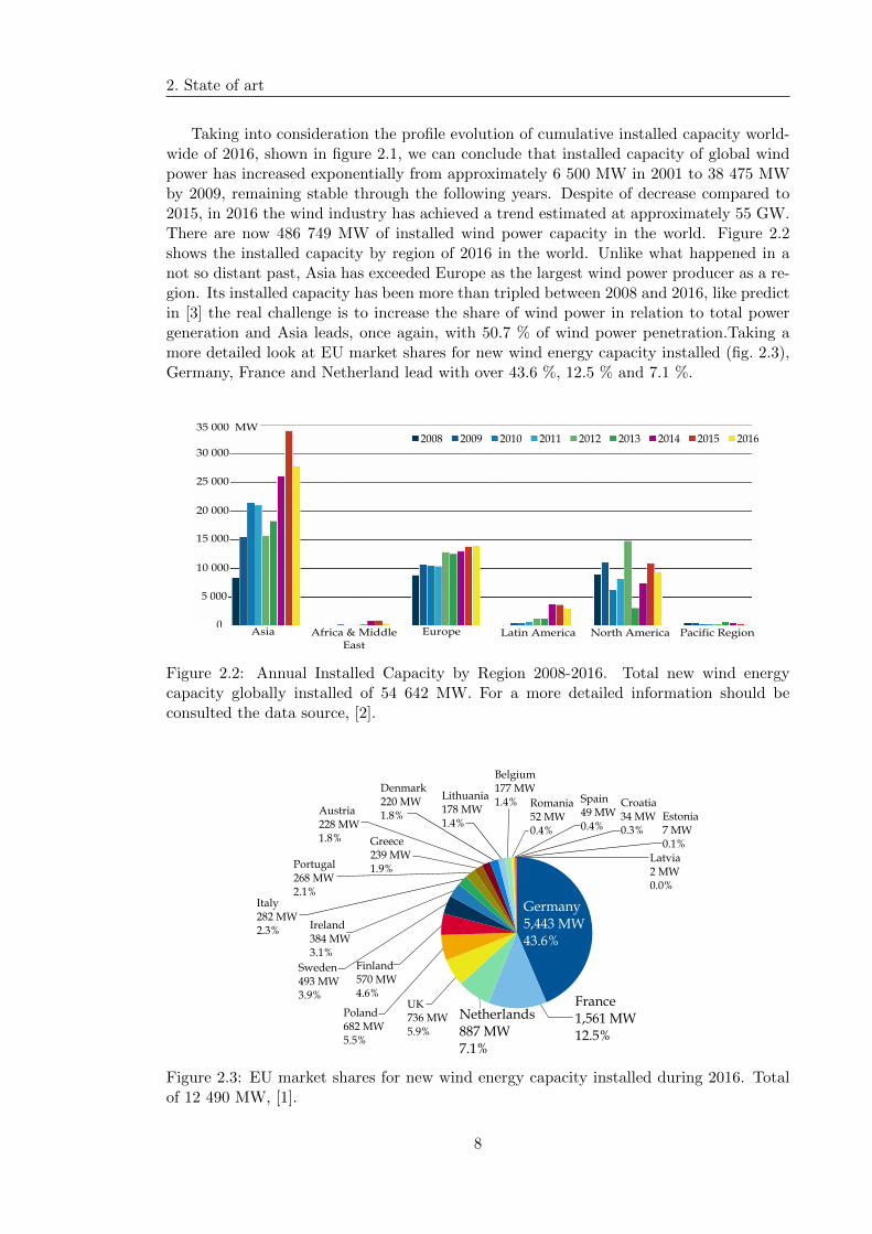
Taking into consideration the profile evolution of cumulative installed capacity world-wide of 2016, shown in figure 2.1, we can conclude that installed capacity of global windpower has increased exponentially from approximately 6 500 MW in 2001 to 38 475 MWby 2009, remaining stable through the following years. Despite of decrease compared to2015, in 2016 the wind industry has achieved a trend estimated at approximately 55 GW.There are now 486 749 MW of installed wind power capacity in the world. Figure 2.2shows the installed capacity by region of 2016 in the world. Unlike what happened in anot so distant past, Asia has exceeded Europe as the largest wind power producer as a re-gion. Its installed capacity has been more than tripled between 2008 and 2016, like predictin [3] the real challenge is to increase the share of wind power in relation to total powergeneration and Asia leads, once again, with 50.7 % of wind power penetration.Taking amore detailed look at EU market shares for new wind energy capacity installed (fig. 2.3),Germany, France and Netherland lead with over 43.6 %, 12.5 % and 7.1 %.
0
5 000
10 000
15 000
20 000
25 000
30 000
35 000 MW201620152014201320122011201020092008
Africa & Middle East
Asia Europe Latin America North America Pacific Region
Figure 2.2: Annual Installed Capacity by Region 2008-2016. Total new wind energycapacity globally installed of 54 642 MW. For a more detailed information should beconsulted the data source, [2].
Portugal268 MW2.1%
Italy282 MW2.3% Ireland
384 MW3.1%
Poland682 MW5.5%
Finland570 MW4.6%
Sweden493 MW3.9%
Greece239 MW1.9%
Netherlands887 MW7.1%
UK736 MW5.9%
Austria228 MW1.8%
Denmark220 MW1.8%
Lithuania178 MW1.4%
Belgium177 MW1.4% Romania
52 MW0.4%
Croatia34 MW0.3%
Latvia2 MW0.0%
Estonia7 MW0.1%
Spain49 MW0.4%
France1,561 MW12.5%
Germany5,443 MW43.6%
Figure 2.3: EU market shares for new wind energy capacity installed during 2016. Totalof 12 490 MW, [1].
8
2.2. Brief overview of wind turbine conversion systems
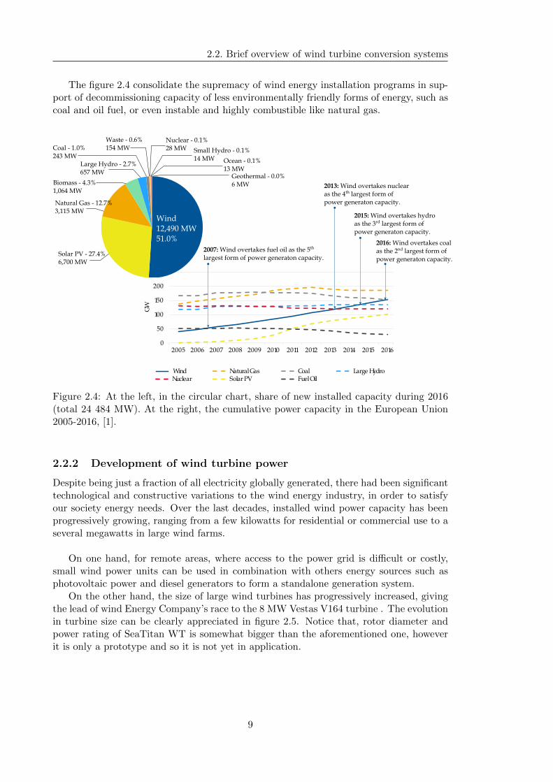
The figure 2.4 consolidate the supremacy of wind energy installation programs in sup-port of decommissioning capacity of less environmentally friendly forms of energy, such ascoal and oil fuel, or even instable and highly combustible like natural gas.
0
50
100
150
200
250
2005 2006 2007 2008 2009 2010 2011 2012 2013 2014 2015 2016
GW
Large HydroWindNuclear
Natural GasSolar PV
CoalFuel Oil
2007: Wind overtakes fuel oil as the 5th
largest form of power generaton capacity.
2013: Wind overtakes nuclear as the 4th largest form of power generaton capacity.
2015: Wind overtakes hydro as the 3rd largest form of power generaton capacity.
2016: Wind overtakes coal as the 2nd largest form of power generaton capacity.
Biomass - 4.3%1,064 MW
Large Hydro - 2.7%657 MW
Coal - 1.0%243 MW
Waste - 0.6%154 MW
Nuclear - 0.1%28 MW Small Hydro - 0.1%
14 MW Ocean - 0.1%13 MW
Geothermal - 0.0%6 MW
Solar PV - 27.4%6,700 MW
Wind12,490 MW51.0%
Natural Gas - 12.7%3,115 MW
Figure 2.4: At the left, in the circular chart, share of new installed capacity during 2016(total 24 484 MW). At the right, the cumulative power capacity in the European Union2005-2016, [1].
2.2.2 Development of wind turbine power
Despite being just a fraction of all electricity globally generated, there had been significanttechnological and constructive variations to the wind energy industry, in order to satisfyour society energy needs. Over the last decades, installed wind power capacity has beenprogressively growing, ranging from a few kilowatts for residential or commercial use to aseveral megawatts in large wind farms.
On one hand, for remote areas, where access to the power grid is difficult or costly,small wind power units can be used in combination with others energy sources such asphotovoltaic power and diesel generators to form a standalone generation system.
On the other hand, the size of large wind turbines has progressively increased, givingthe lead of wind Energy Company’s race to the 8 MW Vestas V164 turbine . The evolutionin turbine size can be clearly appreciated in figure 2.5. Notice that, rotor diameter andpower rating of SeaTitan WT is somewhat bigger than the aforementioned one, howeverit is only a prototype and so it is not yet in application.
9

2. State of art
100
200
300 m
1995 1999 2000
2002
2006
20072012
2013
2014
2016
Vestas V164-8.0MW8000 kWØ 187 mH 164 mOff-shore
Repower 6.2-1526200 kWØ 110 mH 152 mOff-shore
Samsung S7.0-1717000 kWØ 110 mH 171 mOff-shore
SeaTitan10000 kWØ 125 mH 190 mOff-shore
BONUS 450kW/37450 kWØ 40 m H 37 m On-shore
Vestas V66-2.0MW1750 kWØ 66 mH 67 mOn-shore
Vestas V80-2.0MW2000 kWØ 78 m H 80 mOn-shore
Vestas V90-3.0MW3000 kWØ 80 mH 90 m On-shore
REpower5M5000 kWØ 120 mH 126 mOff-shore
ENERCON E-126/7.5MW7500 kWØ 135 mH 127 mOn-shore
Figure 2.5: Evolution of wind turbine size (Ø: rotor diameter; H: tower height). All datacan be founded in different articles, manufactures reports and datasheets, [3–11].
2.2.3 Costs of wind turbine conversion systems
Energy request is expected to increase widely during the following decades. Naturally thisis creating panic that our energy assets are beginning to run out and a worldwide economyworry stands up. As a result of that, we must take account of the cost of energy.
$138
$105
$88$78
$62
$119
$93
$106
$94
$79
$64
$77
$60
$32
$14
$222
$168
$193
$150
$135
$108
$182
$139
$167
$143
$117
$111
$110
$101
$62
$48
$0 $50 $100 $150 $200 $250 $300
Solar PV—Rooftop Residential
Solar PV— Community
Solar Thermal Tower with Storage
Fuel Cell
Geothermal
Biomass Direct
Wind
Levelized Cost ($/MWh)
SubsidizedUnsubsidized
Figure 2.6: Leveled cost of energy in United States. U.S. federal tax subsidies remainan important component of the economics of Alternative Energy generation technologies(and government incentives are, generally, currently important in all regions), [12].
When the first utility-scale turbines were installed in the early 1980s, wind-generatedelectricity cost was $ 0.3 per kWh, [3]. Today, as we can see in the figure 2.6, wind powerplants can generate electricity for $ 0.032 to $ 0.062 per kWh, [12]. Compared with otherenergy resources, alternative or conventional ones, wind energy is one of the most econom-
10
2.3. Wind turbine technology
ically viable renewable energy resources, as illustrated in figure 2.6. Variations in powerrating, operating condition, location and technology used can materially affect the levelof the cost of energy production.
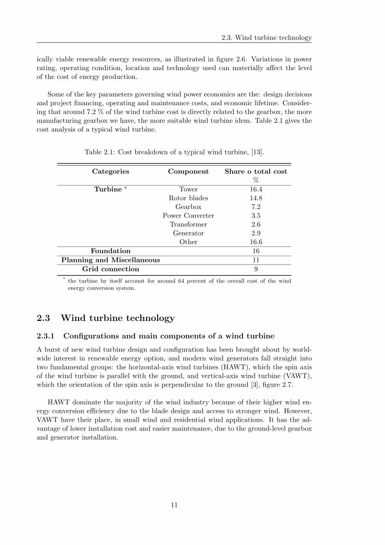
Some of the key parameters governing wind power economics are the: design decisionsand project financing, operating and maintenance costs, and economic lifetime. Consider-ing that around 7.2 % of the wind turbine cost is directly related to the gearbox, the moremanufacturing gearbox we have, the more suitable wind turbine idem. Table 2.1 gives thecost analysis of a typical wind turbine.
Table 2.1: Cost breakdown of a typical wind turbine, [13].
Categories Component Share o total cost%
Turbine ∗ Tower 16.4Rotor blades 14.8
Gearbox 7.2Power Converter 3.5
Transformer 2.6Generator 2.9
Other 16.6
Foundation 16
Planning and Miscellaneous 11
Grid connection 9
* the turbine by itself account for around 64 percent of the overall cost of the windenergy conversion system.
2.3 Wind turbine technology
2.3.1 Configurations and main components of a wind turbine
A burst of new wind turbine design and configuration has been brought about by world-wide interest in renewable energy option, and modern wind generators fall straight intotwo fundamental groups: the horizontal-axis wind turbines (HAWT), which the spin axisof the wind turbine is parallel with the ground, and vertical-axis wind turbine (VAWT),which the orientation of the spin axis is perpendicular to the ground [3], figure 2.7.
HAWT dominate the majority of the wind industry because of their higher wind en-ergy conversion efficiency due to the blade design and access to stronger wind. However,VAWT have their place, in small wind and residential wind applications. It has the ad-vantage of lower installation cost and easier maintenance, due to the ground-level gearboxand generator installation.
11

2. State of art
Rotordiameter
Rotor blade
Rotor shaft
Gearbox
Nacelle
Generator
BrakeYaw
Rotor bearing
Tower
Rotor diameter
Guide wire
Rotorshaft
Rotorblade
Rotor bearing
Generator
BrakeGearbox
Base
Figure 2.7: Horizontal and vertical axis wind turbines, [3].
According to [14], horizontal turbine components include:
� blade or rotor, which converts the energy in the wind to rotational shaft energy;
� a drive train, usually including a gearbox and a generator;
� a tower that supports the rotor and drive train; and
� Other equipment, including controls, electrical cables, ground support equipment,and interconnection equipment.
Blades and Rotor hub The area of the wind generator that accumulates energy of thewind is known as the blades. The wind turns the blades, converting the linear motion ofthe air into circular motion. The Rotor hub is responsible to connect the blades to thedrive train, powering a power generator that supplies a current.
Drive train The generator converts the particular rotation of wind turbines bladesdirectly into electricity. It generally demands rpm’s of just 1500 to at least 1800, whichis far higher than the amount of revolutions per minute of wind turbine blades range.Consequently, most WTs requires a gearbox. It turns the high torque, low speed of thewind into a low torque, high speed of the generator.
Tower and Nacelle The tower elevates the nacelle to provide sufficient space for theblades rotation and to reach better wind conditions. The nacelle supports the rotor huband houses the gearbox, generator, and some others equipment like previously stated.
12
2.4. Gearbox in a wind turbine
2.3.2 Power controls
Wind turbines can also be classified into fixed-speed and variable-speed turbines, achiev-ing maximum conversion efficiency only at a given wind speed and over a wide range ofwind speeds, respectively. In fixed-speed wind turbines, the constant speed that it rotatesis determined by the transmission ratio, the grid frequency, and the number of the polesof the generator, [3].
Turbine blades are aerodynamically optimized to capture the maximum power fromthe wind, the most commonly used methods being pitch and stall controls.
For a robust and simple solution, without mechanical actuators, sensors or controllers,the control method tipically used is the passive stall control. Regarding the stall control,the blades of the turbine are designed, such that, when the wind speed exceeds the ratedwind speed of about 15 m/s, air turbulence is generated on the blade surface that is notfacing the wind, resulting in a reduction in the captured power and preventing turbinedamage.
Conversely, pitch control, which is used in wide-scale wind turbine, turns the blades intheir longitudinal axis, changing the pitch angle through a hydraulic or electromechanicaldevice located in the rotor hub attached to a gear system ate the base of each blade.
Both are used to reduce the captured power at high wind speeds, which prevents tur-bine damage under wind gusts effects. Note however, pitch control shows versatility toconstrain captured power over a wide range of linear motion of the air and, therefore,ensured a more profitable WECS. In cases in which the wind speed is higher than thelimit of about 25 m/s, the blade are pitched completely|1 out of the wind, and thus nopower is captured, [3].
2.4 Gearbox in a wind turbine
As concluded in section 2.2.3, the gearbox is a costly part of an wind turbine, and thusdirect drive|2 generators that operate at lower rotational speeds are being explored. Inthat case, the wind turbine must be able to continuously adjust its rotational speed inorder to keep the tip speed ratio at an optimal value to achieve the maximum powerconversion efficiency at different wind speeds. To make the turbine speed adjustable, thewind turbine generator is normally connected to the utility grid through a power convertsystem. So, in whatever way, this is a dimension, technologic and economical demandingtask and that is why the gearbox-generator system continues to be the most usually.
1it is also known as fully pitched or feathered.2in these machines, the generator rotor turns at the same speed as the turbine rotor, dispensing a
gearbox.
13
2. State of art
2.4.1 Description
Due to the loading and environmental conditions in which the gearbox must operate, itsdesign is a huge challenging job. In fact, for example, it may be exposed to an ambienttemperature range of -29 °C to +50 °C |3, [15].
To address the operating constraints, the design of the gearbox shall be made in ac-cordance with IEC 61400 Wind turbine standard. For the current calculation of fatigueresistance, this standard suggests to have a look at guide values of gear and bearingstandards by ISO/TR. For instance, the ISO 6336 gear standard provides an establishedmethod for calculating resistance to subsurface contact failure and for tooth root breakagebut these are neither the only nor the most usual failure modes in WT gearboxes. In fact,for this kind of application, the gearbox collapse depends for the most part on: manufac-turing errors, such as grind temper or material inclusions; surface related problems; and,problems from small vibratory motions. Along with poor lubrication, such issues can causesurfaces overheating and its subsequent adhesive wear. This meet scuffing, micropitting,and fretting problems, resulting in the detachment and transfer of particles from one orboth of the meshing teeth, [16]. So, information on some of these specific troubles can befound in the fourth part of IEC 61400 standard. Many wind-turbine gearboxes have alsosuffered from fundamental design issues such as ineffective interference fits that result inunintended motion and wear, ineffectiveness of internal lubrication paths and problemswith sealing.
Regarding the operating revolutions, the rotor of a large three-blades wind turbineusually operates in a speed range from 6-20 rpm, [3], what is much slower than a standardwind generator with a rated speed about 1500 or 1000 rpm and 1800 or 1200 rpm, witha 4 or 6 poles for a 50 Hz and 60 Hz generator frequency, respectively. So, a gearboxis needed to increase rotational speed from a low-speed rotor to a higher speed electricalgenerator. This is because of the power grid frequency, typically, 50 Hz in Europe and 60Hz in the United States.
For a given generator frequency in Hz, f , and number of poles, np, the generator shaftspeed in rpm, ngen, can be determinate by:
ngen =120f
np. (2.1)
The gearbox conversion ratio|4, i, is designed to match the high speed generator withthe low speed turbine blades, and it is given by them ratio,
i =ngennrotor
. (2.2)
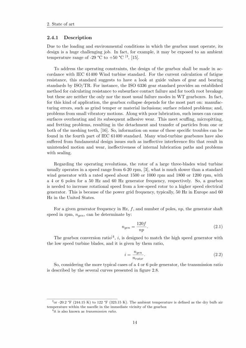
So, considering the more typical cases of a 4 or 6 pole generator, the transmission ratiois described by the several curves presented in figure 2.8.
3or -20.2 °F (244.15 K) to 122 °F (323.15 K). The ambient temperature is defined as the dry bulb airtemperature within the nacelle in the immediate vicinity of the gearbox
4it is also known as transmission ratio.
14
2.4. Gearbox in a wind turbine
6 8 10 12 14 16 1850
100
150
200
250
300
Tra
nsm
isio
n r
ati
o, i
nrotor , rpm
4 poles6 poles
50 Hz 60 Hz
Figure 2.8: Transmission ratio i versus the rated turbine speed nrotor, [3].
Among the different configuration, like spur or helical gears and parallel or planetarystages, two or more gear types and gear stages may be combined to achieve the high con-version ratio needed to couple the turbine rotor and the generator.
Based on a rotor speed of around 15 rpm, we can claim that, for a 1500 rpm outputfor the generator, a 100:1 transmission ratio is considered and it would play a pivotal rulein the stages layout selection. Most installations have one generator, i.e. the gearbox hasexactly one input and one output. Although the chosen design is up to manufactures,it is common to find one planetary-two helical stages transmission for lower powergearboxes. In multimegawatt WT, gearbox are more likely to have a multi-stage planetaryarrangement, than the few megawatts ones. Epicyclical gear stages provide high load ca-pacity and compactness to gear drives offering a multitude of gearing options and a largechange in RPM within small volume. The limitation of planetary gearbox is the need forhighly complex design and the general inaccessibility of important parts and high loadson the shaft bearings. Cooling of the gearbox is done by the gearbox oil, [17].
2.4.2 Concepts
Considering the gearbox mission and according to their kinematics type, wind turbinegearboxes can be classified as follows, [18]:
� standard gearboxes that constantly transform input torque and speed values intothose at the output;
� torque-limiting gearboxes can limit the output torque and, as a consequence,limiting the input torque. The speed is thereby not controlled.
� CVTs gearbox that permit the control of the gearbox output speed and torque|5.
As described above, i.e. bearing in mind that one input-one output configuration iscommonplace, most of the WT gearbox assume one of the following described configura-tions.
5within a determined range.
15
2. State of art
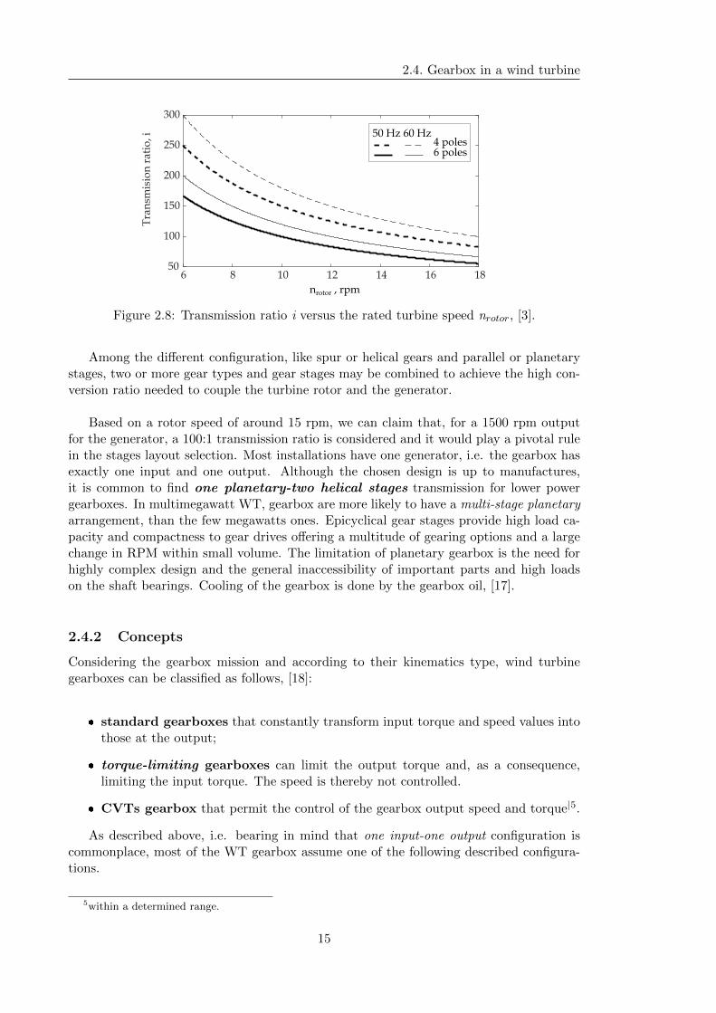
Figure 2.9: Three spur wheel stages ar-rangement, [18].
Figure 2.10: One planetary-Two parallelstages gearbox, [18].
The three spur wheel stages gearbox (see fig. 2.9) is a typical concept for the lowercapacity generator. As the name suggests, the single transmission ratio of each stage isgiven by the ratio between its input speed and its output speed, or directly by the ratiobetween the number of gear teeth like shown by the Equation (2.3). The three spur wheelstages gearbox , like all other examples, normally works with helical gears for lower noise.
uthree spur wheel =noutnin
=
voutroutvinrin
=routrin
=ZoutZin
(2.3)
In the one planetary-two parallel stages arrangement (fig. 2.10), the sun gear|6 is en-gaged with a portion of the planet gear|7 that is in mesh with the stationary ring gear|8,commonly ring gear is part of casing. In this type of meshing it is require a offset in thelayout of the gear stages.
1 2
3
4
O
B
A
C
vB
r1
r2r3
r4
vA
ω1
ω2
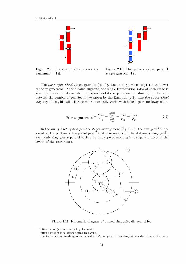
Figure 2.11: Kinematic diagram of a fixed ring epicyclic gear drive.
6often named just as sun during this work.7often named just as planet during this work.8due to its internal meshing, often named as internal gear. It can also just be called ring in this thesis
16
2.4. Gearbox in a wind turbine
Taking into account the stationarity of the gear ring 3 and the kinematic diagram ofthe figure 2.11, based on the kinematic diagram of the Figure 2.11 the circumferentialspeed at the point A can be established by,
vA = r2ω2, (2.4)
which is related to the linear speed at point B by the following relation,
vB = 2vA. (2.5)
It is worth noting that the distance from point C to point B is twice the distancebetween points C and A. Since there is a linear relationship with the circumferential speedof a point and it’s the straight distance from the instantaneous centre of rotation, theEquation (2.5) is true.
Analysing the Figure 2.11 we can conclude, too, that the linear speed of the point Bis also given by,
vB = r1ω1. (2.6)
With the definition of the gear pitch radius,
r =Zm
2(2.7)
where Z and m are its number of teeth and nominal module, respectively, we can obtainthe following expression by matching the Equations (2.5) and (2.6),
2vA = r1ω1
2r2ω2 = r1ω1
2 (r1 + r4)ω2 = r1ω1
2 (r1 + r4)n2 = r1n1
2
(Z1m
2+Z4m
2
)n2 =
Z1m
2n1
2 (Z1 + Z4)n2 = Z1n1
(2Z1 + 2Z4)n2 = Z1n1 (2.8)
Substituting the relation Z3 = Z1 + 2Z4 in equation (2.8), it can be rewritten,
(2Z1 + Z3 − Z1)n2 = Z1n1
(Z1 + Z3)n2 = Z1n1 (2.9)
Finally, according to the previous Equation (2.9), the transmission ratio for the plan-etary stage of the mentioned gearbox concept is given by,
ione planetary-two parallel =noutnin
= 1 +Z3
Z1(2.10)
and its practical range varies from 3:1 to 9:1.
17
2. State of art
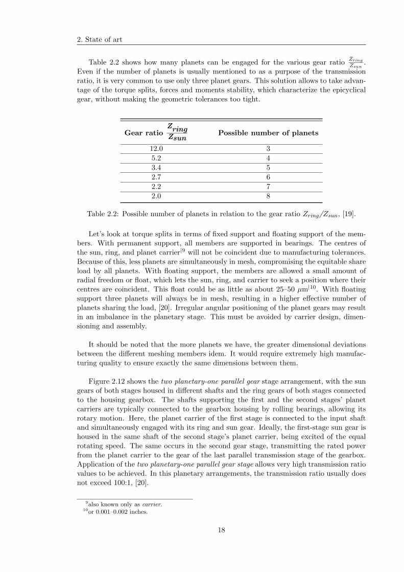
Table 2.2 shows how many planets can be engaged for the various gear ratioZring
Zsun.
Even if the number of planets is usually mentioned to as a purpose of the transmissionratio, it is very common to use only three planet gears. This solution allows to take advan-tage of the torque splits, forces and moments stability, which characterize the epicyclicalgear, without making the geometric tolerances too tight.
Gear ratioZringZsun
Possible number of planets
12.0 3
5.2 4
3.4 5
2.7 6
2.2 7
2.0 8
Table 2.2: Possible number of planets in relation to the gear ratio Zring/Zsun, [19].
Let’s look at torque splits in terms of fixed support and floating support of the mem-bers. With permanent support, all members are supported in bearings. The centres ofthe sun, ring, and planet carrier|9 will not be coincident due to manufacturing tolerances.Because of this, less planets are simultaneously in mesh, compromising the equitable shareload by all planets. With floating support, the members are allowed a small amount ofradial freedom or float, which lets the sun, ring, and carrier to seek a position where theircentres are coincident. This float could be as little as about 25–50 µm|10. With floatingsupport three planets will always be in mesh, resulting in a higher effective number ofplanets sharing the load, [20]. Irregular angular positioning of the planet gears may resultin an imbalance in the planetary stage. This must be avoided by carrier design, dimen-sioning and assembly.
It should be noted that the more planets we have, the greater dimensional deviationsbetween the different meshing members idem. It would require extremely high manufac-turing quality to ensure exactly the same dimensions between them.
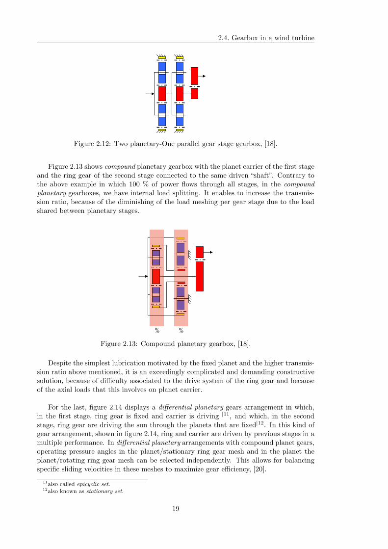
Figure 2.12 shows the two planetary-one parallel gear stage arrangement, with the sungears of both stages housed in different shafts and the ring gears of both stages connectedto the housing gearbox. The shafts supporting the first and the second stages’ planetcarriers are typically connected to the gearbox housing by rolling bearings, allowing itsrotary motion. Here, the planet carrier of the first stage is connected to the input shaftand simultaneously engaged with its ring and sun gear. Ideally, the first-stage sun gear ishoused in the same shaft of the second stage’s planet carrier, being excited of the equalrotating speed. The same occurs in the second gear stage, transmitting the rated powerfrom the planet carrier to the gear of the last parallel transmission stage of the gearbox.Application of the two planetary-one parallel gear stage allows very high transmission ratiovalues to be achieved. In this planetary arrangements, the transmission ratio usually doesnot exceed 100:1, [20].
9also known only as carrier.10or 0.001–0.002 inches.
18
2.4. Gearbox in a wind turbine
Figure 2.12: Two planetary-One parallel gear stage gearbox, [18].
Figure 2.13 shows compound planetary gearbox with the planet carrier of the first stageand the ring gear of the second stage connected to the same driven “shaft”. Contrary tothe above example in which 100 % of power flows through all stages, in the compoundplanetary gearboxes, we have internal load splitting. It enables to increase the transmis-sion ratio, because of the diminishing of the load meshing per gear stage due to the loadshared between planetary stages.
% %
Figure 2.13: Compound planetary gearbox, [18].
Despite the simplest lubrication motivated by the fixed planet and the higher transmis-sion ratio above mentioned, it is an exceedingly complicated and demanding constructivesolution, because of difficulty associated to the drive system of the ring gear and becauseof the axial loads that this involves on planet carrier.
For the last, figure 2.14 displays a differential planetary gears arrangement in which,in the first stage, ring gear is fixed and carrier is driving |11, and which, in the secondstage, ring gear are driving the sun through the planets that are fixed|12. In this kind ofgear arrangement, shown in figure 2.14, ring and carrier are driven by previous stages in amultiple performance. In differential planetary arrangements with compound planet gears,operating pressure angles in the planet/stationary ring gear mesh and in the planet theplanet/rotating ring gear mesh can be selected independently. This allows for balancingspecific sliding velocities in these meshes to maximize gear efficiency, [20].
11also called epicyclic set.12also known as stationary set.
19

2. State of art
Figure 2.14: Differential planetary gearbox, [18].
In the following figure 2.15 some others gearbox concepts are illustrated.
(a) (b)
(c) (d)
Figure 2.15: Several gearbox concepts: (a)Planetary gear stage, fixed Planet: Renk Aero-gear; (b) Hydraulic torque limiting: Henderson Gearbox; (c) Power Split, several Genera-tors: Clipper ; (d) Two inputs: Luv and Lee Rotor, Kowintec, [18].
20

2.4. Gearbox in a wind turbine
2.4.3 Market search
Parameters like wind turbine operating power and rotation speed of the rotor (or blades)are influencing parameters in the gearbox conception. A conscious choice must be madeaccording to the needs of today’s energy suppliers. The aim of the market share analysisis to obtain the trend lines of the most important parameters between the main companythat originally built and work with wind turbine technology.
In this context, it is once again essential to design an applicable transmission group;thus, the market research proves to be relevant, in a way it allows the mapping out of thedimensions and mass values, as well as, its suspension mechanisms.
As reported by the statistics portal Statista, Vestas reclaimed the top spot in the an-nual ranking of wind turbine manufactures, with a 16 percent of the world’s market sharefor wind turbines. General Electric paired with Goldwind placed second with 12 percent,followed by Gamesa (8 %), Enercon (7 %), Siemens (6 %), and like many others.
Vestas(Denmark)
GE Energy(U.S.)
Goldwind(China)
Gamesa(Spain)
Enercon(Germany)
Siemens(Germany)
Nordex Acciona(Germany)
Mingyang(China)
Envision(China)
United Power(China)
Othermanufacturers
Market share%
0 2.5 5 7.5 10 12.5 15 17.5 20 22.5 25 27.5
16 %
12 %
12%
8 %
7 %
6%
5 %
4 %
4 %
4 %
25 %
Figure 2.16: Global market share of the world’s leading wind turbine manufacturers in2016, [21].
In Table 2.3, we can consult the relevant characteristics of conventional wind turbinesof some top manufactures. And, by conventional, we can say gearbox-generator windturbine. About Vestas and Goldwind’s WTs, there are no available information and agearless technology eliminates the gearbox in the system, having only one moving part inthe drivetrain. Despite of the reduction of the lifetime maintenance costs of the turbine,its manufacturing process and technologic development is extremely expensive, comparedto a conventional one.
21
2. State of art
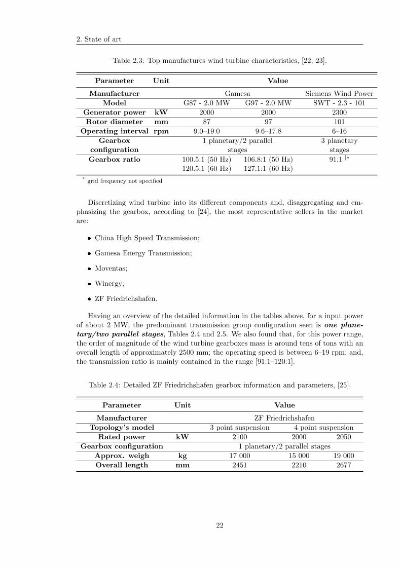
Table 2.3: Top manufactures wind turbine characteristics, [22; 23].
Parameter Unit Value
Manufacturer Gamesa Siemens Wind Power
Model G87 - 2.0 MW G97 - 2.0 MW SWT - 2.3 - 101
Generator power kW 2000 2000 2300
Rotor diameter mm 87 97 101
Operating interval rpm 9.0–19.0 9.6–17.8 6–16
Gearbox 1 planetary/2 parallel 3 planetaryconfiguration stages stages
Gearbox ratio 100.5:1 (50 Hz) 106.8:1 (50 Hz) 91:1 |∗
120.5:1 (60 Hz) 127.1:1 (60 Hz)
* grid frequency not specified
Discretizing wind turbine into its different components and, disaggregating and em-phasizing the gearbox, according to [24], the most representative sellers in the marketare:
� China High Speed Transmission;
� Gamesa Energy Transmission;
� Moventas;
� Winergy;
� ZF Friedrichshafen.
Having an overview of the detailed information in the tables above, for a input powerof about 2 MW, the predominant transmission group configuration seen is one plane-tary/two parallel stages, Tables 2.4 and 2.5. We also found that, for this power range,the order of magnitude of the wind turbine gearboxes mass is around tens of tons with anoverall length of approximately 2500 mm; the operating speed is between 6–19 rpm; and,the transmission ratio is mainly contained in the range [91:1–120:1].
Table 2.4: Detailed ZF Friedrichshafen gearbox information and parameters, [25].
Parameter Unit Value
Manufacturer ZF Friedrichshafen
Topology’s model 3 point suspension 4 point suspension
Rated power kW 2100 2000 2050
Gearbox configuration 1 planetary/2 parallel stages
Approx. weigh kg 17 000 15 000 19 000
Overall length mm 2451 2210 2677
22
2.4. Gearbox in a wind turbine
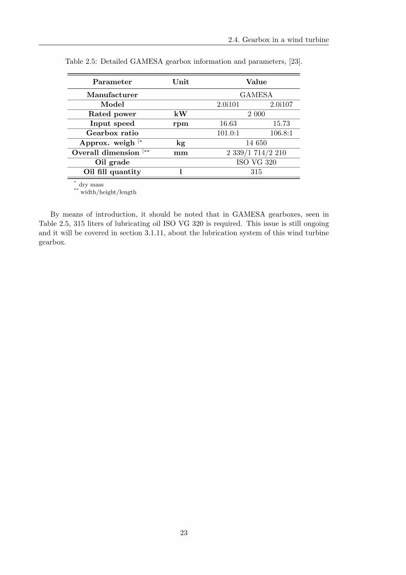
Table 2.5: Detailed GAMESA gearbox information and parameters, [23].
Parameter Unit Value
Manufacturer GAMESA
Model 2.0i101 2.0i107
Rated power kW 2 000
Input speed rpm 16.63 15.73
Gearbox ratio 101.0:1 106.8:1
Approx. weigh |∗ kg 14 650
Overall dimension |∗∗ mm 2 339/1 714/2 210
Oil grade ISO VG 320
Oil fill quantity l 315
* dry mass** width/height/length
By means of introduction, it should be noted that in GAMESA gearboxes, seen inTable 2.5, 315 liters of lubricating oil ISO VG 320 is required. This issue is still ongoingand it will be covered in section 3.1.11, about the lubrication system of this wind turbinegearbox.
23

2. State of art
24

Part II
25


Chapter 3
Gearbox Design and Dimensioning
This section is especially set up for the purpose of (i) defining the structure of wind tur-bine; (ii) clarifying and explaining the choices of the layout and design of its transmissioncomponent; and, (iii) dimensioning the mechanical elements. The dimensioning of themechanical elements is based mainly on KISSsoft® calculations.
3.1 Transmission
Before we can discuss the different type of gear, it shall be defined what gear means. Inmore technically correct terms as possible, a gear is a toothed wheel that is usually, butnot necessarily, round, [26]. Used with the purpose of transmitting motion and/or powerfrom one shaft to another, there are multiple varieties of profiles that its teeth may have.So, it’s prior to define that a involute-based form was considered, at least for parallel axisgears, the most common tooth form, [26]. Involute-based form performs simple manufac-turing, low flexibility to small changes in center distance, strength and durability, thatother “involute brothers” don’t present. Given its geometrical and kinematic complexity,it is essential to define notation symbols for the data processing relating to its resistanceand meshing calculation. By meshing is meant a set of two coupled toothed wheel. So,the insulated element is called a gear and the one with the lowest number of teeth is oftenknown as pinion, [27].
The nomenclature used in this paper is suggested by International Standards Organization—ISO 701:1998.
3.1.1 Number of transmission stages
The definition of the kinematic chain of the gearbox was the first step of the design in thiswork, and it was fundamental in all subsequent decisions taken. The first decision to bemade was based on the number of stages required to achieve the desired speed increase.As suggested in the previous chapter, given the high order of magnitude of the turbineinput power, it would be unfeasible a solution of only one transmission stage. Consideringthat four stages of multiplication speed would force more mechanical elements that intro-duce power losses in the system, we have the solutions of two and three transmission stages.
According to the graph of the figure 2.8 and considering a nominal rotor speed of thearound 15 rpm, it can be seen that the range of the conversion speed ratio for these gear-boxes is roughly 60:1 to 150:1. The choice of a two stages solution could translate into
27

3. Gearbox Design and Dimensioning
a transmission ratio for the first stage of at least 8:1. This would result in a very severemultiplication of the speed, and hence a very severe torque reduction, in each of the stages.This could cause increased power losses due to uncontrolled sliding effects, consequence ofthe high gear modules and the high rolling bearing size required.
That said, in order to ensure a more energy-dimensionally efficient solution, the threestage conversion solution would be chosen.
3.1.2 Shaft arrangement
3.1.2.1 1st Stage
The gears can be classified based on the arrangement of the axes of the gear pair, whichtransmit the rotational movement. In this work, parallel axis gears are fully used, and inthe first stage of speed multiplication, a particular case of it is considered—The epicyclicgear drive.
Epicyclic gear are increasingly used. Having undertaked a brief study of these mecha-nisms, indicating mathematical and graphical methods of calculations in Section 2.4.2.
It will be showed that it should not be used early, too. This because in certain config-urations we would risk achieving extremely low meshing efficiency, [28].
In this respect, an epicyclic gear drive is composed of the following main parts:
� Two coaxial shafts with different rotational speeds and on which are mounted thesun gear and the ring gear, respectively;
� A articulated chassis which turns about an axis corresponding to the axis of theprevious shafts. It rotates at its own speed and supports the planet gears, providinga connection between the other two coaxial shafts.
3.1.2.2 2nd and 3rd Stages
Having decided the gear arrangement for the first stage, focus can shift to the second andthird stages. It has been considered the WT gearbox as a two single gearboxes coupled,one planetary and two parallel shaft stages. This decision was made considering that therewas already done a foregoing work about the second part of the gearbox. In other words,a numerically proven comparison of he different parallel shaft arrangement was previouslybeen presented at the master thesis of Joao Pedro Sousa, [29]. Thus, the starting pointfor the selection and definition of the gear stages in question shall be the results of thatwork.
As stated by [29], the parallel stages offer significant flexibility in their configurationand, so, the single branch and double branch arrangement were studied and compared.The single branch is the most convectional arrangement of the transmission, being such awidely applicable as a low cost design and manufacturing.
An alternative is double branch arrangement. Through the division of the rated power,this solution presents a robustness far superior them the previous one. That is, with the
28

3.1. Transmission
double branch it is allowed to split the power by several paths, where each of them onlyknows a percentage of the total power of the system. In this way, considering each of thegear paths separately, we are facing a configuration with a appreciably lower magnitude ofsize, working with lower nominal modules than the single branch arrangement. This notonly allows a more compact and robust solution as an extremely advantageous solution interms of maintenance costs. It must be noted that it has the major advantage that in caseof failure of the components after the torque splitting, these components can be removedfor repair, keeping the turbine partly operational until the repair is completed.
3.1.3 Gear type and Helix angle
It is important to stress that the spur gears are the most common and most used typeof gear; however, helical teeth enter the meshing zone progressively and, therefore, havea smoother action than a spur gear teeth and tend to be quieter, which is a major addedvalue according to the problem definition set in Section 1.3. This is because, at helix anglegreater than zero, it is possible to get several axial pitches, fig. 3.1, within the facewidth ofeach helix, allowing higher contact ratio between both meshed gear. It is also known thatsmaller helical gears have the same load carrying capacity, than a spur gear. For that,helical ger teeth are fully used in this WTG.
β
axial
pitch
Figure 3.1: Axial pitch of a helical gear.
Having in mind that parallel axis gear is the most efficient type (or form) of gearingand used in this gearbox, single helical and double helical gear shall be studied and com-pared.
3.1.3.1 1st Stage
Regarding the first stage, we would do well to start clarifying that planetary stages havesimultaneously internal and external meshing; so, we have to be aware that they bothmust have the same helix angle, but be of different and same hand, respectively.
As for the double helical teeth, there is no far application in the planetary gear typebecause of the difficulty of construction, [30]. For that, and for a rather extensive amountof time required for few improvement, a single helical gear was considered. It should notbe forgotten that to provide the helix’s improvement in the transmission, the contact ratioprovided by the helix angle |1, εβ, must be at least unity, otherwise for analytical purposesthe gear is treated as if were a spur gear.
1according to ISO, it can also be called overlap ratio; by AGMA, we often found face overlap.
29

3. Gearbox Design and Dimensioning
As stated in preceding section, a decreasing of the noise level and a increasing of theload capacity is verified with the implementation of the helix angle; however, at anglesmuch above 15° to 20°, the strength of the root teeth is compromised because of the de-crease of the transverse tooth thickness, [26]. Having this into account, a helix angle of15° was chosen.
3.1.3.2 2nd and 3rd Stages
Based on the study comparison introduced by [29], a double helical gear was chosen for thesecond part of the gearbox. Although the slightly dimensional disadvantage identified, aimportant profit was registered about the power losses in the rolling bearings.
That is, the helical gears produce an end thrust along the axes direction, forcing theapplication of the tapered roller bearing. In fact, this kind of rolling bearing have highvalues of power losses, at a high rotational speed. Since the second and third stages arethose with the highest gearbox speed, it is interesting to avoid their use. Then, with thedouble helical gear chose, we obtain the noise benefits of the single helical gears withoutthe disadvantage of thrust loading and, because of that, a higher helices angle could beconsidered.
Despite the smoother operation, higher helix angles provide tooth strength diminish-ing. This being the case, the selection of helix angle must be carefully evaluated to ensurethat it is strong enough to take the loads in question.
When the gears are made double helical, there is no thrust load because the thrust ofone helix is opposed by an equal and opposite thrust from the other helix, [26]. Attentionmust be paid to the balance of the forces between each of the double teeth. If the stiffnessof the double helical gear with its own shaft is too high, the division of load in a doublehelical gear may be impaired, due to the manufacturing errors and disparities. And so, afloat configuration must be applied. Il will require a higher helix angle, in order to pro-vide a reduction of resistance to axial float resulting from friction in coupling devices (likeshaft). In order to achieve this decreasing of frictional resistance without compromisingthe root teeth resistance, helix angle of 25 ° was chosen.
3.1.4 Module and number of teeth
The choices of the module values and the number of teeth associated with each stage weremade in the sense of minimizing the size of its gears, as well as increasing its efficiency.In addition, the ratio between the number of teeth in each pair, i.e. the gear ratio of eachstage should be a rational number, namely a periodic fractional number, so as to mini-mize repeated contact between the same pair of teeth, which can suppress the number ofworking teeth, promoting the propagation of wear failures, or even, the root breakage ofteeth. Looking at the second and third stages of transmission, although the gear ratio is afractional number it doesn’t follow the criteria of a periodic fractional number. This choicewas conscious and it had the aim of simplifying the calculation of the angular positionof the intermediate pinion in relation to the respective spline of each intermediate shafts.This matter will be dealt with in the ensuing section 4.1.3.
30
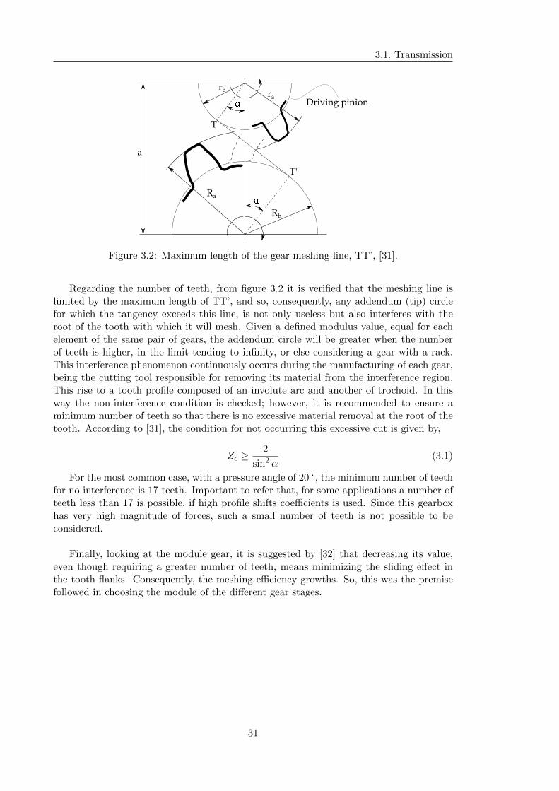
3.1. Transmission
a
rbra
�
Ra
Rb
�
T
T'
Driving pinion
Figure 3.2: Maximum length of the gear meshing line, TT’, [31].
Regarding the number of teeth, from figure 3.2 it is verified that the meshing line islimited by the maximum length of TT’, and so, consequently, any addendum (tip) circlefor which the tangency exceeds this line, is not only useless but also interferes with theroot of the tooth with which it will mesh. Given a defined modulus value, equal for eachelement of the same pair of gears, the addendum circle will be greater when the numberof teeth is higher, in the limit tending to infinity, or else considering a gear with a rack.This interference phenomenon continuously occurs during the manufacturing of each gear,being the cutting tool responsible for removing its material from the interference region.This rise to a tooth profile composed of an involute arc and another of trochoid. In thisway the non-interference condition is checked; however, it is recommended to ensure aminimum number of teeth so that there is no excessive material removal at the root of thetooth. According to [31], the condition for not occurring this excessive cut is given by,
Zc ≥2
sin2 α(3.1)
For the most common case, with a pressure angle of 20 °, the minimum number of teethfor no interference is 17 teeth. Important to refer that, for some applications a number ofteeth less than 17 is possible, if high profile shifts coefficients is used. Since this gearboxhas very high magnitude of forces, such a small number of teeth is not possible to beconsidered.
Finally, looking at the module gear, it is suggested by [32] that decreasing its value,even though requiring a greater number of teeth, means minimizing the sliding effect inthe tooth flanks. Consequently, the meshing efficiency growths. So, this was the premisefollowed in choosing the module of the different gear stages.
31

3. Gearbox Design and Dimensioning
Table 3.1: Number of teeth and module of final gearbox parameters.
Gear stage Element No. Teeth Transmission ratio Modulemm
1st sun 26 5.181 16planet 41ring 109
2nd gear 120 4.8 8pinion 25
3rd gear 100 4 5pinion 25
3.1.5 Facewidth
In the design of helical gears, the facewidth is usually based on which it the required load-carrying capacity needed, [26]. In addition, [26] suggest that it is necessary to obtain atleast two axial pitches of facewidth, being this value as great as the operating rotationalspeed.
In fact, the choice of gear facewidth should not be independent of the analysis of itsoverall size magnitude. This is, an uncontrolled increase in the facewidth of a gear couldhave heavy costs in its production, since with the increase in facewidth plus the difficultyin ensuring the accuracy of geometry along the entire length of the gear tooth. In orderto avoid torsional twist concentrations, the maximum limiting value suggested by [26] forany helical gear pair is equal to its pinion reference diameter. It may cause quite heavyloads at the end of the gear, making impossible to get tooth contact across this muchfacewidth. For the particular case of a double helical gearing, a face width up to 1.75times the pinion pitch may be applied. Regarding the bending resistance issues, with bothsingle and double helical gears, profile teeth modification should be considered in order tominimize its effect. It will be detailed in ensuing section.
Therefore, the facewidth chosen for all toothed elements of this kinematic chain werepresented in the Table 3.2. It has to be said that the option of a low facewidth-axial pitchratio for the planetary gearing was intended not only with the above mentioned manufac-turing and geometry quality issues, but also with its low operating speed.
32
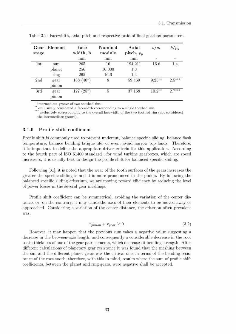
3.1. Transmission
Table 3.2: Facewidth, axial pitch and respective ratio of final gearbox parameters.
Gear Element Face Nominal Axial b/m b/pystage width, b module pitch, py
mm mm mm - -
1st sun 265 16 194.211 16.6 1.4planet 256 16.000 1.3ring 265 16.6 1.4
2nd gear 188 (40∗) 8 59.469 9.25∗∗ 2.5∗∗∗
pinion
3rd gear 127 (25∗) 5 37.168 10.2∗∗ 2.7∗∗∗
pinion
* intermediate groove of two toothed rim.** exclusively considered a facewidth corresponding to a single toothed rim.*** exclusively corresponding to the overall facewidth of the two toothed rim (not considered
the intermediate groove).
3.1.6 Profile shift coefficient
Profile shift is commonly used to prevent undercut, balance specific sliding, balance flashtemperature, balance bending fatigue life, or even, avoid narrow top lands. Therefore,it is important to define the appropriate driver criteria for this application. Accordingto the fourth part of ISO 61400 standard , for wind turbine gearboxes, which are speedincreasers, it is usually best to design the profile shift for balanced specific sliding.
Following [31], it is noted that the wear of the tooth surfaces of the gears increases thegreater the specific sliding is and it is more pronounced in the pinion. By following thebalanced specific sliding criterium, we are moving toward efficiency by reducing the levelof power losses in the several gear meshings.
Profile shift coefficient can be symmetrical, avoiding the variation of the center dis-tance, or, on the contrary, it may cause the axes of their elements to be moved away orapproached. Considering a variation of the center distance, the criterion often prevalentwas,
xpinion + xgear ≥ 0. (3.2)
However, it may happen that the previous sum takes a negative value suggesting adecrease in the between-axis length, and consequently a considerable decrease in the roottooth thickness of one of the gear pair elements, which decreases it bending strength. Afterdifferent calculations of planetary gear resistance it was found that the meshing betweenthe sun and the different planet gears was the critical one, in terms of the bending resis-tance of the root tooth; therefore, with this in mind, results where the sum of profile shiftcoefficients, between the planet and ring gears, were negative shall be accepted.
33
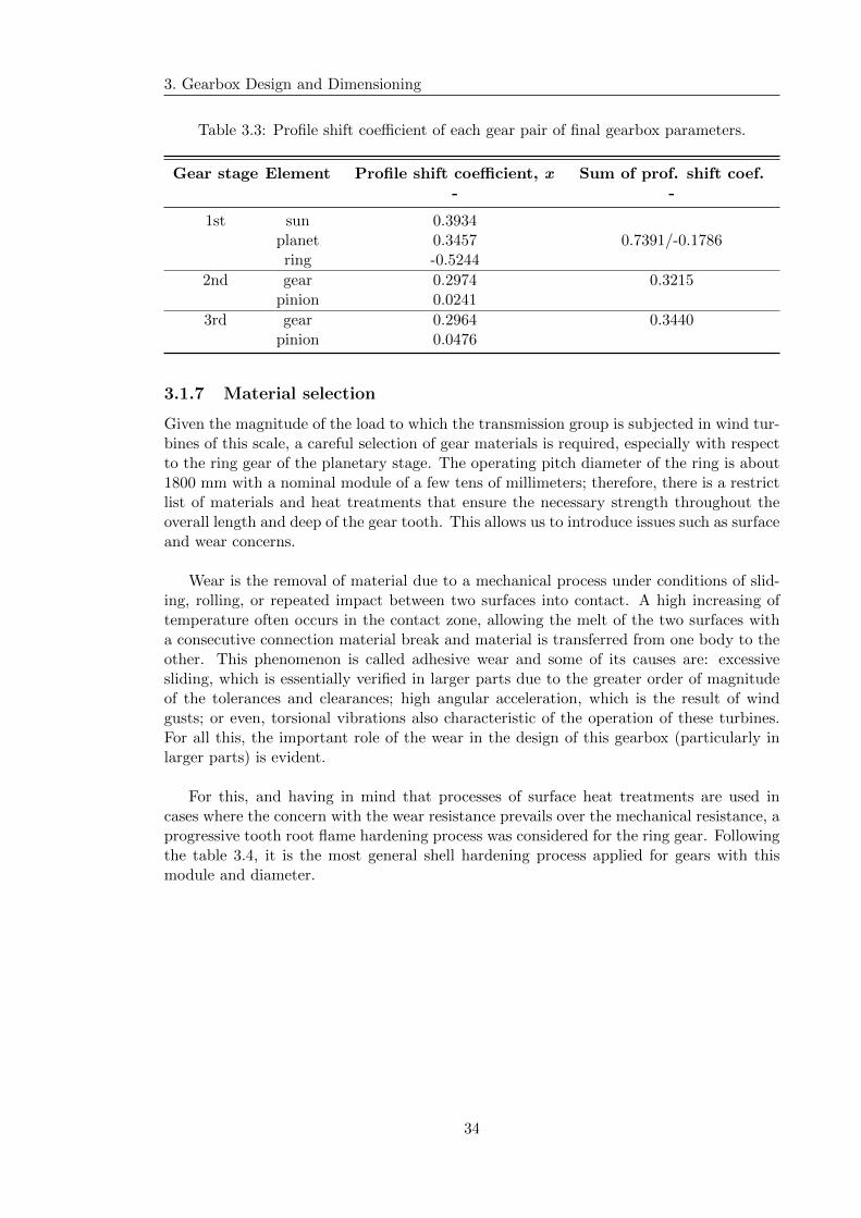
3. Gearbox Design and Dimensioning
Table 3.3: Profile shift coefficient of each gear pair of final gearbox parameters.
Gear stage Element Profile shift coefficient, x Sum of prof. shift coef.- -
1st sun 0.3934planet 0.3457 0.7391/-0.1786ring -0.5244
2nd gear 0.2974 0.3215pinion 0.0241
3rd gear 0.2964 0.3440pinion 0.0476
3.1.7 Material selection
Given the magnitude of the load to which the transmission group is subjected in wind tur-bines of this scale, a careful selection of gear materials is required, especially with respectto the ring gear of the planetary stage. The operating pitch diameter of the ring is about1800 mm with a nominal module of a few tens of millimeters; therefore, there is a restrictlist of materials and heat treatments that ensure the necessary strength throughout theoverall length and deep of the gear tooth. This allows us to introduce issues such as surfaceand wear concerns.
Wear is the removal of material due to a mechanical process under conditions of slid-ing, rolling, or repeated impact between two surfaces into contact. A high increasing oftemperature often occurs in the contact zone, allowing the melt of the two surfaces witha consecutive connection material break and material is transferred from one body to theother. This phenomenon is called adhesive wear and some of its causes are: excessivesliding, which is essentially verified in larger parts due to the greater order of magnitudeof the tolerances and clearances; high angular acceleration, which is the result of windgusts; or even, torsional vibrations also characteristic of the operation of these turbines.For all this, the important role of the wear in the design of this gearbox (particularly inlarger parts) is evident.
For this, and having in mind that processes of surface heat treatments are used incases where the concern with the wear resistance prevails over the mechanical resistance, aprogressive tooth root flame hardening process was considered for the ring gear. Followingthe table 3.4, it is the most general shell hardening process applied for gears with thismodule and diameter.
34
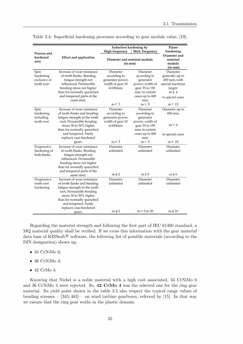
3.1. Transmission
Table 3.4: Superficial hardening processes according to gear module value, [19].
Process and hardened area
Effect and application
Induction hardening by Flame hardeningHigh frequency Med. Frequency
Diameter and nominal module (in mm)
Diameter and nominal module(in mm)
Spin hardening exclusive of tooth root
Increase of wear resistance of tooth flanks. Bending
fatigue strength not influenced. Permissible
bending stress not higher than for normally quenched and tempered parts of the
same steel.
Diameter according to
generator power; width of gear 10
to100mm;
Diameter according to
generator power; width of
gear 35 to 150 mm; in certain cases up to 400
mm;
Diameter generally up to 450 mm; with
special machines larger;m � 6
in special cases
m � 3 m � 5 m � 12
Spin hardening including tooth root
Increase of wear resistance of tooth flanks and bending fatigue strength in the tooth
root. Permissible bending stress 30 to 50% higher
than for normally quenched and tempered. Partly
replaces case-hardened gears.
Diameter according to
generator power; width of gear 10
to100mm;
Diameter according to
generator power; width of
gear 35 to 150 mm; in certain cases up to 400
mm;
Diameter up to 450 mm;
m � 6
in special cases
m � 5 m � 5 m � 10
Progressive hardening of both flanks
Increase of wear resistance of tooth flanks. Bending
fatigue strength not influenced. Permissible
bending stress not higher than for normally quenched and tempered parts of the
same steel.
Diameter unlimited
Diameter unlimited
Diameter unlimited
m � 2 m � 5 m � 6
Progressive tooth root hardening
Increase of wear resistance of tooth flanks and bending fatigue strength in the tooth
root. Permissible bending stress 30 to 50% higher
than for normally quenched and tempered. Partly
replaces case-hardened gears.
Diameter unlimited
Diameter unlimited
Diameter unlimited
m � 2 m = 5 to 30 m � 10
Regarding the material strength and following the first part of IEC 61400 standard, aMQ material quality shall be verified. If we cross this information with the gear materialdata base of KISSsoft® software, the following list of possible materials (according to theDIN designation) shows up,
� 34 CrNiMo 6;
� 36 CrNiMo 4;
� 42 CrMo 4.
Knowing that Nickel is a noble material with a high cost associated, 34 CrNiMo 6and 36 CrNiMo 4 were rejected. So, 42 CrMo 4 was the selected one for the ring gearmaterial. Its yield point shown in the table 3.5 also respect the typical range values ofbending stresses —[345; 483]— on wind turbine gearboxes, referred by [15]. In that waywe ensure that the ring gear works in the plastic domain.
35

3. Gearbox Design and Dimensioning
Table 3.5: 42 CrMo 4 (DIN) mechanical properties, [33].
Yield strength Tensile strengthMPa Mpa
≥ 500 ≥ 755
Contrary to what happens with the ring, it is important that the core of the sun gear,which will be manufactured directly on the shaft and hence have to allow low deflection,to provide high yield strength. Regarding the planet gears, which shall house its taperedroller bearing, a bore surface hardness at least of 55 HRC is suggested by the WT stan-dard IEC 61400. Bearing this in mind and considering the high strength and hardenabilitythat were required, the material chosen was the 18 CrNiMo 7-6 case-carburized and -hardened (tab. 3.6). The same for the all others gears.
Table 3.6: 18 CrNiMo 7-6 (DIN) mechanical properties, [33].
Yield strength Tensile strengthMPa Mpa
≥ 735 ≥ 885
It is important to state that following the material selection drivers of ISO 61400-1, thematerial strength values shall be at least correspondent to the MQ quality. Wind turbinegears require smooth tooth surfaces to ensure adequate load capacity. Smooth surfaces areespecially important with regard to micropitting resistance. Roughly, for external gearsmaximum flank surface roughness shall be Ra = 0,8 µm. Maximum flank surface roughnessfor internal gears shall be Ra = 1,6 µm. IEC 61400-4 standard suggest a specific surfaceroughness level for each gear stage. It is shown in the Table 3.7 and it was considered inthe KISSsoft® calculation.
Table 3.7: Recommended gear tooth surface roughness, [34].
Gear Ra(µm)
high speed pinion and gear ≤ 0.7intermediate pinion and gear ≤ 0.7
low speed pinion and gear ≤ 0.6low speed sun and planet ≤ 0.5
36
3.1. Transmission
3.1.8 Input and Output conditions
3.1.8.1 General conditions
With the information so far, it is possible to set the wind turbine gearbox input and op-eration conditions.
Since the gearbox have a input power of 2.0 MW, having in mind what was saidin Section 2.4.1, an input speed of 15 rpm is chosen as the nominal input speed of thegearbox. Notice that, according to the Table 2.5, this is near to the market rates of thewind turbine gearboxes industry.
Typical generators for gearbox-generator wind turbine have 4 poles. Bearing this inmind, according to the Equation (2.1) for a 4 pole, 50 Hz generator, a output speed of1500 rpm is needed, which is provided by a overall transmission ratio|2 of about 1:100.
As stated in Section 2.4.1, a wind turbine gearbox normally have multiple stages toachieve the high conversion ratio. So, supported by the research presented in Section 2.4.3,a one planetary/two parallel stages has been chosen. It is widely used for a rated powerwind turbine about 2.0 MW. For the transmission ratio of each stage, a 7 x 4 x 3.6 |3 groupof transmission ratio was proposed for this design.
In fact, a decreasing of each stage transmission ratio is typically verified along the trans-mission chain. However, high transmission ratio imply high dimensional pinion variationin relation to the gear size, compromising the objective of a compact design as possible.Given the first planetary stage, the magnitude of size will be essentially defined by theexternal diameter of the ring, so a more uniform distribution of the single transmissionratios should be studied. The selected one was the 5.2 x 4.8 x 4 group of transmissionratios. This change can determine a significant reduction of the outer gearbox diameter.So, a detailed comparison between the first purposed group of transmission ratio and thelast was made.
3.1.8.2 Operating temperature
Considering the operating conditions presented in Section 2.4.1, a 40 °C ambient temper-ature is considered. This decision was to avoid considering nominal operating conditionsclose to the limit conditions, but without making a too strict and inflexible choice bringingexcessive oversizing of the WT gearbox.
3.1.8.3 Required life time
The design life time of a wind turbine is defined, in the first part of IEC 61400, as atleast 20 years, so it is expected to ensure that gearbox have at least the same durability.Considering that, 175 200 hours of service was regarded as its required life time.
As it will be shown in following chapters, it was considered for gearbox optimizationa design load cases that, contrarily what happens in above sentence, took into account
2also known as global transmission ratio.3each of the values represent the multiplication factor of the speed, per stage.
37

3. Gearbox Design and Dimensioning
particular load cases like parked time. It embody the requirements for loads resulting fromatmospheric turbulence that occurs during normal operation of a wind turbine throughoutits lifetime. DLC also embodies the requirements for ultimate loading resulting from ex-treme turbulence conditions, specific transient cases that have been selected as potentiallycritical events in the life of a wind turbine.
Regarding the rolling bearings, its design shall consider the expected amount of rota-tion during gearbox lifetime. Modified reference rating life Lnmrh shall be calculated inaccordance with ISO/TS 16281 and it shall meet or exceed the specified design lifetimefor the gearbox (175 200 hours). Notice that IEC 61400 recommends to considered apermissible failure probability equal or less than 10 percent. So, when setting the rollingbearing life time it should not be forgotten that a 10 percent of failure probability wasconsidered.
3.1.9 Load factors
3.1.9.1 Application factor, KA
One of the input parameters of KISSsoft® calculation tool is the application factor KA.It classifies the operational behavior of driver and driven elements of the system accordingto the following table,
Table 3.8: Assignment of operational behavior to application factor. Adapted from theKISSsof® software instructions.
Operating behavior of Operational behavior of the driven machinethe driving machine
uniform moderate shocks medium heavy shocks
uniform 1.00 1.25 1.50 1.75ligth shocks 1.10 1.35 1.60 1.85
moderate shocks 1.25 1.50 1.75 2.00heavy shocks 1.50 1.75 2.00 2.25
Considering that the rotor turbine occasionally suffers peaks of loads resulting, forexample, from wind bursts and bearing in mind a continuous operation of the gearbox thechosen application factor was,
KA = 1.25. (3.3)
3.1.9.2 Dynamic factor, KV
The dynamic facto KV considers the load increase on the flank and on the root becauseof toothing rigidity variations during meshing. Should the frequency of the rigidity vari-ations/number of revolutions be directly comparable to the meshing inherent frequency,so will appear dynamic additional stresses, [18]. Wind turbine standard of IEC mentionsthat if the calculation indicates a dynamic factor less than 1.05, a KV of 1.05 shall beconsidered as a minimum value.
It is known that the dynamic factor has a significantly effect about gear rating, andafter a few gearing calculation it was detected that without make any value restrictions,
38
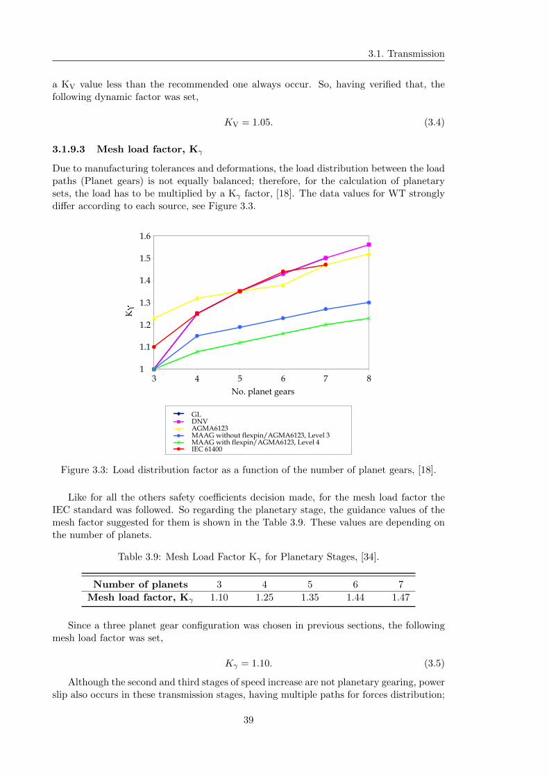
3.1. Transmission
a KV value less than the recommended one always occur. So, having verified that, thefollowing dynamic factor was set,
KV = 1.05. (3.4)
3.1.9.3 Mesh load factor, Kγ
Due to manufacturing tolerances and deformations, the load distribution between the loadpaths (Planet gears) is not equally balanced; therefore, for the calculation of planetarysets, the load has to be multiplied by a Kγ factor, [18]. The data values for WT stronglydiffer according to each source, see Figure 3.3.
K
�
1.6
1.5
1.4
1.3
1.2
1.1
13 4 5 6 7 8
No. planet gears
GLDNVAGMA6123MAAG without flexpin/AGMA6123, Level 3MAAG with flexpin/AGMA6123, Level 4IEC 61400
Figure 3.3: Load distribution factor as a function of the number of planet gears, [18].
Like for all the others safety coefficients decision made, for the mesh load factor theIEC standard was followed. So regarding the planetary stage, the guidance values of themesh factor suggested for them is shown in the Table 3.9. These values are depending onthe number of planets.
Table 3.9: Mesh Load Factor Kγ for Planetary Stages, [34].
Number of planets 3 4 5 6 7
Mesh load factor, Kγ 1.10 1.25 1.35 1.44 1.47
Since a three planet gear configuration was chosen in previous sections, the followingmesh load factor was set,
Kγ = 1.10. (3.5)
Although the second and third stages of speed increase are not planetary gearing, powerslip also occurs in these transmission stages, having multiple paths for forces distribution;
39
3. Gearbox Design and Dimensioning
so, the factor Kγ chosen for the first stage was also applied in the last stages of transmission.
3.1.9.4 Load Distribution Factors, KHα and KHβ
The transverse factor KHα considers the effects of an uneven load increase on the flank dueto pitch errors and irregular load distribution over several teeth in meshing. According to[34], because of the toothing qualities required for wind turbine gearboxes, a unitary loaddistribution factor KHα may be considered.
The effect of meshing force distribution over the toothing width upon the flank loadsare described by the face load factor KHβ. In addition to this extreme loads, the influenceof production variation on shaft parallelism and tooth alignment of pinion and gear shouldbe included in the value of mesh misalignment, and included in the KHβ definition.
Load distribution factors recommended are presented in the following table.
Table 3.10: Pitting resistance, bending strength and scuffing resistance safety factors forthe final gearbox solution, [34].
Transverse load factor KHα Face load factor KHβ
1.00 1.15
3.1.10 Safety factors
Root safety, flank safety and safety against scuffing at flash temperature were the criteriatook into account for gear sizing, service life time, and later, for load spectrum calculations.
In earlier times, the mechanical designer tried to calculate a “safe” stress. It wasthought that all parts with less than the safe stress limit would perform without failure,[26]. In fact, mechanical components, such as gears, have a probability of failure. In orderto minimize it, several safety coefficients should be considered, defining a safe stress rangein which the gear can operate with a low probability of failure.
The failure modes of gears include plastic fracture and/or deformation of the teethand/or gear body, damage to the surface of the teeth, and corrosion, [35]. Typically,fracture occurs at the root of the tooth, in fatigue processes caused by many load cycles,where it may be possible to identify fatigue cracks at the fracture surface. There may alsobe fractures originating from the body of the gear (eg, from the spline feature). Flankdefects include pitting and scuffing due to localized micro-welding effects.
In order to minimize the probability of the aforementioned rupture, the following safetyfactors was considered as the minimum recommended (tab. 3.11).
3.1.11 Lubricant and lubricating method
3.1.11.1 Lubricating oil selection
Lubrication is one of the most delicate issues in the operation of a gear. It is known thatin the gear meshing process, great thermal and pressure loads can occur on the teeth in
40
3.1. Transmission
Table 3.11: Pitting resistance, bending strength and scuffing resistance safety factors forthe final gearbox solution, [34].
Safety factor for Safety factor for Safety factor forfor pitting resistance bending strength for scuffing resistance
SH SF SB
1.25 1.56 1.3
contact, may even cause them to melt and, consequently, the breakage of the mechanism.Thus, through several lubrication methods it is possible to form a lubricant film whichseparates the surfaces by avoiding metal-to-metal joint. This will obviously contribute toa decrease in the friction coefficient between the surfaces in contact.As mentioned above,there is a thermal effect associated with the contact of the teeth during the engagement.Also here the lubricating film seems indispensable in the way that it provide the evacu-ation of the heat generated. Like that, the materials ruin of the operating gear pair, athigh temperatures, is prevented.
It is extremely important to clarify that the three main conditions for lubrication arethe following:
� geometry (convergent shape);
� speed;
� viscosity (body).
In other words, and very briefly, when velocity-excited, the lubricant is guided to azone of convergence (the beginning zone of the meshing), suffering a smashing effect and,therefore, the formation of a lubricating film which separate both teeth flanks in contact.
The choice of the type of lubricant takes into account specifications such as:
� transmitted power;
� operating and start-up temperatures;
� gear type;
� gear speed and transmission ratio;
� load characteristics;
� expected life-time;
� application method.
These factors lead to the determination of the physical, chemical and operational prop-erties of the oil to be used, whose properties are closely related to multiple constrains likekinematic and dynamic viscosity, viscosity index, pour point, additives and costs.
Given the range of low speed and high torque of the wind turbine gearbox, the IEC61400-4 standard recommends the use of a mineral or synthetic oil base. Although mineral
41

3. Gearbox Design and Dimensioning
oils are less expensive, synthetic oils have lower pour point which means lower feed tem-perature and thus lower energy costs associated with cold start preheating mechanisms. Inaddition, synthetic lubricants have a high viscosity index; so, they table a higher thermalinertia than mineral oils, providing a less significant temperature-properties (e.g. viscos-ity) variation or, in other words, a more stability of the lubricant behavior.
In a gearbox it is advantageous to operate at temperatures as low as possible so thatthe integrity of the components is not compromised; thus, once again, the synthetic oilsshow to be the best option since they allow the operation of the gears at lower tempera-tures than those obtained with oils of mineral base. Low operating temperatures ensurelonger gear and rolling bearing life due to the increased film thickness. It also provide ahigher life estimate for the lubricant by decreasing the oxidation effect, which is extremelyimportant due to the long life expected for the wind turbine conversion system.
Table 3.12: Characteristics of the OptigearTM Synthetic 1710, OptigearTM Synthetic Xand OptigearTM Synthetic A oils.
Parameter Unit Value
Oil family Synthetic 1710 Synthetic X Synthetic ADensity @ 15 °C kg/m3 875 822 870
Kin. viscosity @ 40 °C mm2/s 320 325 330Kin. viscosity @ 100 °C mm2/s 31.2 34.9 33
Viscosity index 138 152 140Flash point °C 240 250 220Pour point °C -30 -33 -36
In order to fulfil the needs of planetary gears stages, it is general practice to useISO VG 320 grade lubricants for wind turbine multiplication gearbox, [36]. So, after asearch in the manufacturers’ catalogs, the three synthetic oil families was chosen to com-pare: OptigearTM Synthetic 1710, OptigearTM Synthetic X and OptigearTM Synthetic A,table 3.12.
Regarding the gear type, helical gear and double helical gear have a sliding componentalong the line of contact, which is result of the helix angle. This has little or no effect onthe film in the contact area; however,in the convergent zone the sliding component tendsto wipe the lubricant sideways. For that, not as much lubricant is available to be drawninto the contact area, being the resultant pressure increase in the convergent zone ratherlower. These effects may contribute to a need for slightly higher viscosity lubricants. Withthe Synthetic X and Synthetic A having higher and similar viscosity levels, both shows ascandidate oils for this gearbox.
Transmission ratio influences the selection of lubricating oil as long as the higher itsvalue the more gears stages must exist. The low speed gear in the gear set is usually themost critical in the formation of the EHD film, [37]. At low gear speeds more time is avail-able for oil to be squeezed from the contact area and less oil is drawn into the convergentzone. For that, higher viscosity oil are required. Here, Synthetic X oil is preferred since, athigher temperatures, it has higher viscosity values than other ones do. The higher speedof the last gear stage provide higher sliding and rolling speed of individual teeth. To help
42

3.1. Transmission
reduce the fiction effect resultant of that, a EP additive are recommended.
Gears design for higher power ratings will have wider teeth, teeth of larger cross section(or both), which shall cause mechanical and fluid friction to be greater. As a result, largergear sets, transmitting more power, tend to run hotter. Considering this severe operatingconditions, the use of additives is a necessary practice. Ideally it would be beneficial to uselubricant compositions adapted to the needs of each stage — extreme pressure additives(EP) for high-speed stages and anti wear additives (AW) for high torque stages — butthis is not an efficient practice in way it would imply a sealed sectioning of the differentstages in order to avoid contamination. Therefore, a compromise between the two typesof additives is achieved with the use of this Castrol Optigear oil.
It should be noted that, the nature of the load on any gear set also have an importancein oil lubricating selection. In some operations, the conditions may be more severe owingto overloads or to a combination of heavy loads and extreme shock loads. Despite of beingconsidered during the calculation process (like presented in ensuing section 4.1.1), thiscondition generally requires the use of extreme pressure (EP) oils.
In summary, starting with the oil base and bearing in mind the advantages of using fullysynthetic base oils, synthetic 1710 is the first that was excluded due to its mineral/PAO oilbase. It is also possible to choose between Synthetic X and Synthetic A; however, based onall the conditions aforementioned, the lubricant chosen was the Castrol Optigear Syn-thetic X 320. This, as stated by the manufacturer, is ideal for gearboxes with planetarygear temperatures between -35 °C and + 90 °C|4, [38]. The fully synthetic polyalphaolefinebase oils have a significant role in this type of application due to the excellent viscosity-temperature behavior provided by the high viscosity index, low coefficient of friction andgood miscibility with additives, [36].
3.1.11.2 Pressure viscosity parameters
The factors k and s are used to determine the pressure viscosity coefficient, α. The k valueis a linear multiple, while the s value is an exponential power for the dynamic viscosity, µ.These coefficients were checked and applied in accordance with the AGMA 925-A03 [39]standard, and they are presented in the following table.
Table 3.13: Data for determining pressure–viscosity coefficient (acc. to AGMA 925-A03[39]): k and s factors.
Lubricant ISO VG grade k s
PAO 320 0.010326 0.0507
3.1.11.3 Scuffing and micropitting tests parameters
Scuffing occurs locally where the gears are in mesh, i.e. where the roughness peaks incontact temperatures rise sharply (flash temperatures), depending on the load, peripheral
4According to standard [34], selection of the correct viscosity grade for the gearbox must be based onthe operating conditions and not on the start-up ones; and, therefore, operating temperature range — from-29 °C to +50 °C — proposed by [15] must not be forgotten.
43
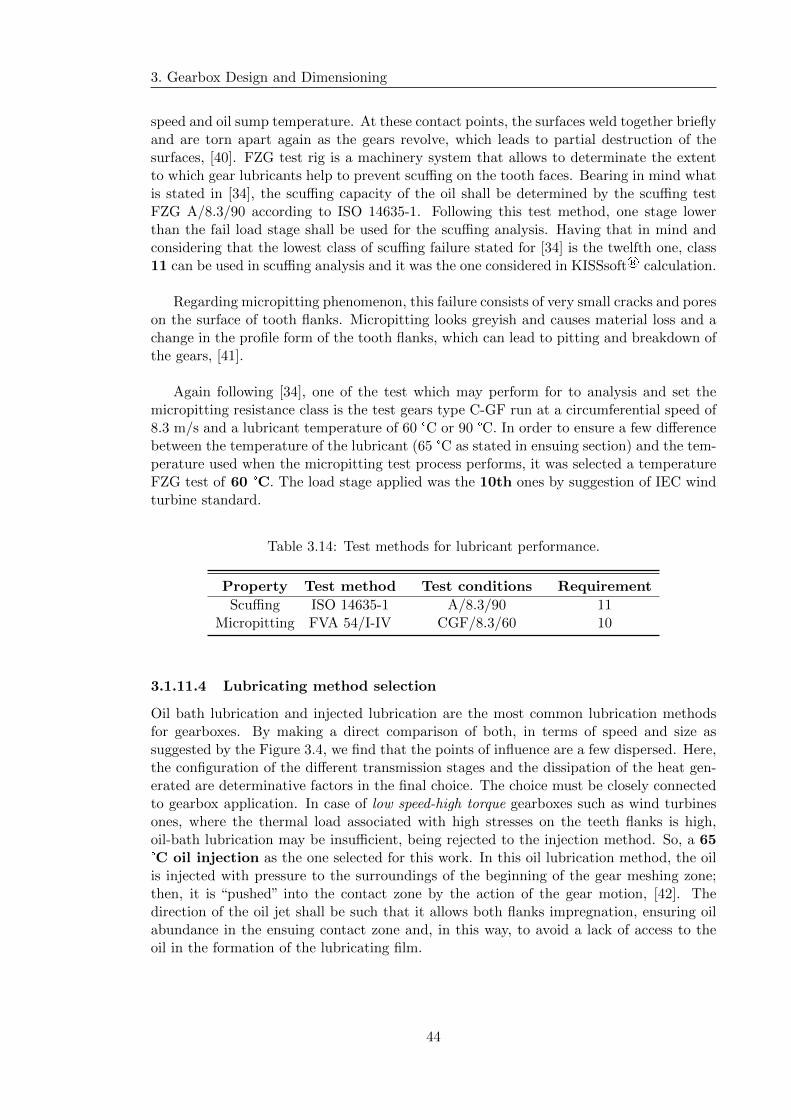
3. Gearbox Design and Dimensioning
speed and oil sump temperature. At these contact points, the surfaces weld together brieflyand are torn apart again as the gears revolve, which leads to partial destruction of thesurfaces, [40]. FZG test rig is a machinery system that allows to determinate the extentto which gear lubricants help to prevent scuffing on the tooth faces. Bearing in mind whatis stated in [34], the scuffing capacity of the oil shall be determined by the scuffing testFZG A/8.3/90 according to ISO 14635-1. Following this test method, one stage lowerthan the fail load stage shall be used for the scuffing analysis. Having that in mind andconsidering that the lowest class of scuffing failure stated for [34] is the twelfth one, class11 can be used in scuffing analysis and it was the one considered in KISSsoft® calculation.
Regarding micropitting phenomenon, this failure consists of very small cracks and poreson the surface of tooth flanks. Micropitting looks greyish and causes material loss and achange in the profile form of the tooth flanks, which can lead to pitting and breakdown ofthe gears, [41].
Again following [34], one of the test which may perform for to analysis and set themicropitting resistance class is the test gears type C-GF run at a circumferential speed of8.3 m/s and a lubricant temperature of 60 °C or 90 °C. In order to ensure a few differencebetween the temperature of the lubricant (65 °C as stated in ensuing section) and the tem-perature used when the micropitting test process performs, it was selected a temperatureFZG test of 60 °C. The load stage applied was the 10th ones by suggestion of IEC windturbine standard.
Table 3.14: Test methods for lubricant performance.
Property Test method Test conditions Requirement
Scuffing ISO 14635-1 A/8.3/90 11Micropitting FVA 54/I-IV CGF/8.3/60 10
3.1.11.4 Lubricating method selection
Oil bath lubrication and injected lubrication are the most common lubrication methodsfor gearboxes. By making a direct comparison of both, in terms of speed and size assuggested by the Figure 3.4, we find that the points of influence are a few dispersed. Here,the configuration of the different transmission stages and the dissipation of the heat gen-erated are determinative factors in the final choice. The choice must be closely connectedto gearbox application. In case of low speed-high torque gearboxes such as wind turbinesones, where the thermal load associated with high stresses on the teeth flanks is high,oil-bath lubrication may be insufficient, being rejected to the injection method. So, a 65°C oil injection as the one selected for this work. In this oil lubrication method, the oilis injected with pressure to the surroundings of the beginning of the gear meshing zone;then, it is “pushed” into the contact zone by the action of the gear motion, [42]. Thedirection of the oil jet shall be such that it allows both flanks impregnation, ensuring oilabundance in the ensuing contact zone and, in this way, to avoid a lack of access to theoil in the formation of the lubricating film.
44
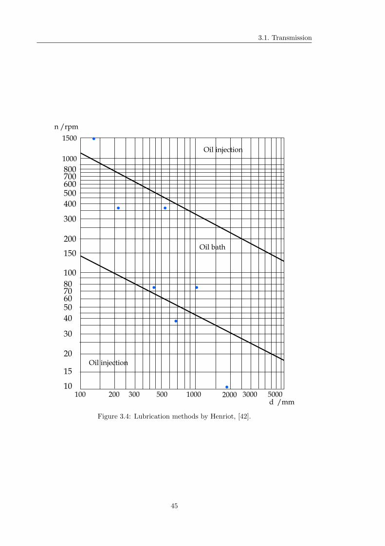
3.1. Transmission
Oil injection
Oil injection
Oil bath
d /mm
n /rpm
1000
1500
100 200 300 500 1000 2000 3000 500010
15
20
30
40
50607080
100
150
200
300
500
400
600700800
Figure 3.4: Lubrication methods by Henriot, [42].
45
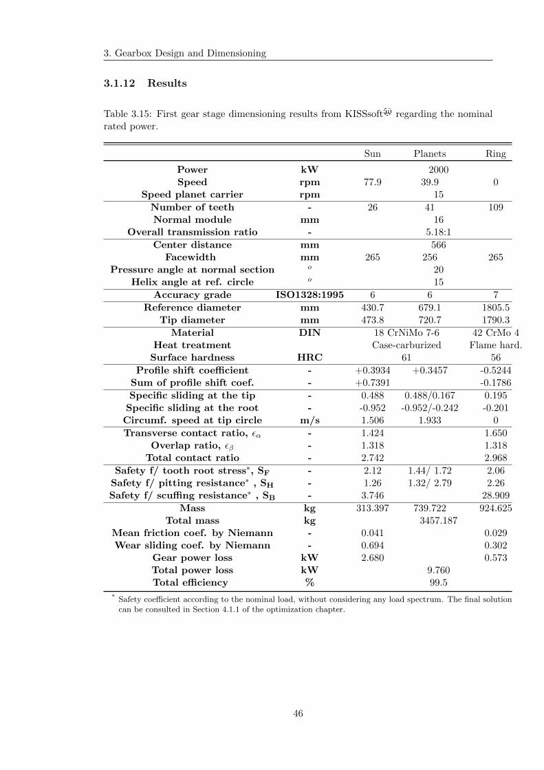
3. Gearbox Design and Dimensioning
3.1.12 Results
Table 3.15: First gear stage dimensioning results from KISSsoft® regarding the nominalrated power.
Sun Planets Ring
Power kW 2000Speed rpm 77.9 39.9 0
Speed planet carrier rpm 15
Number of teeth - 26 41 109Normal module mm 16
Overall transmission ratio - 5.18:1
Center distance mm 566Facewidth mm 265 256 265
Pressure angle at normal section o 20Helix angle at ref. circle o 15
Accuracy grade ISO1328:1995 6 6 7
Reference diameter mm 430.7 679.1 1805.5Tip diameter mm 473.8 720.7 1790.3
Material DIN 18 CrNiMo 7-6 42 CrMo 4Heat treatment Case-carburized Flame hard.
Surface hardness HRC 61 56
Profile shift coefficient - +0.3934 +0.3457 -0.5244Sum of profile shift coef. - +0.7391 -0.1786
Specific sliding at the tip - 0.488 0.488/0.167 0.195Specific sliding at the root - -0.952 -0.952/-0.242 -0.201Circumf. speed at tip circle m/s 1.506 1.933 0
Transverse contact ratio, εα - 1.424 1.650Overlap ratio, εβ - 1.318 1.318
Total contact ratio - 2.742 2.968
Safety f/ tooth root stress∗, SF - 2.12 1.44/ 1.72 2.06Safety f/ pitting resistance∗ , SH - 1.26 1.32/ 2.79 2.26Safety f/ scuffing resistance∗ , SB - 3.746 28.909
Mass kg 313.397 739.722 924.625Total mass kg 3457.187
Mean friction coef. by Niemann - 0.041 0.029Wear sliding coef. by Niemann - 0.694 0.302
Gear power loss kW 2.680 0.573Total power loss kW 9.760Total efficiency % 99.5
* Safety coefficient according to the nominal load, without considering any load spectrum. The final solutioncan be consulted in Section 4.1.1 of the optimization chapter.
46

3.1. Transmission
Table 3.16: Second gear stage dimensioning results from KISSsoft® regarding the nominalrated power.
Gear Pinion
Power∗ kW 1000Speed rpm 77.9 373.8
Number of teeth - 120 25Normal module mm 8
Overall transmission ratio - 4.8:1
Center distance mm 642.500Total facewidth of gear mm 188
Width of intermediate groove mm 40Facewidth for calculation mm 74
Pressure angle at normal section o 20Helix angle at ref. circle o 25
Accuracy grade ISO1328:1995 6
Reference diameter mm 1059.2 220.7Tip diameter mm 1075.6 241.4
Material DIN 18 CrNiMo 7-6Heat treatment Case-carburized
Surface hardness HRC 61
Profile shift coefficient - +0.0241 +0.2974Sum of profile shift coef. - +0.3215
Specific sliding at the tip - 0.409 0.409Specific sliding at the root - -0.691 -0.691Circumf. speed at tip circle m/s 4.387 4.724
Transverse contact ratio, εα - 1.437Overlap ratio, εβ - 1.244
Total contact ratio - 2.682
Safety f/ tooth root stress∗∗, SF - 1.51 1.64Safety f/ pitting resistance∗∗ , SH - 1.27 1.27Safety f/ scuffing resistance∗∗ , SB - 2.980
Mass kg 1293.154 57.701Total mass∗∗∗ kg 1408.56
Mean friction coef. by Niemann - 0.044Wear sliding coef. by Niemann - 0.587
Gear power loss kW 4.537Total power loss kW 9.074Total efficiency % 99.546
* Rated power for each single power path of the mentioned double branch stage.** Safety coefficient according to the nominal load, without considering any load spectrum. The final solution
can be consulted in Section 4.1.1 of the optimization chapter.*** Total mass including the gear and both pinion.
47

3. Gearbox Design and Dimensioning
Table 3.17: Third gear stage dimensioning results from KISSsoft® regarding the nominalrated power.
Gear Pinion
Power∗ kW 1000Speed rpm 373.8 1495.4
Number of teeth - 100 25Normal module mm 5
Overall transmission ratio - 4:1
Center distance mm 346.500Total facewidth of gear mm 127
Width of intermediate groove mm 25Facewidth for calculation mm 51
Pressure angle at normal section o 20Helix angle at ref. circle o 25
Accuracy grade ISO1328:1995 6
Reference diameter mm 551.7 137.9Tip diameter mm 562.1 150.8
Material DIN 18 CrNiMo 7-6Heat treatment Case-carburized
Surface hardness HRC 61
Profile shift coefficient - +0.0476 +0.2964Sum of profile shift coef. - +0.3440
Specific sliding at the tip - 0.417 0.417Specific sliding at the root - -0.715 -0.715Circumf. speed at tip circle m/s 11.002 11.810
Transverse contact ratio, εα - 1.430Overlap ratio, εβ - 1.372
Total contact ratio - 2.802
Safety f/ tooth root stress∗∗, SF - 1.67 1.80Safety f/ pitting resistance∗∗ , SH - 1.69Safety f/ scuffing resistance∗∗ , SB - 3.089
Mass kg 237.020 15.223Total mass∗∗∗ kg 267.466
Mean friction coef. by Niemann - 0.041Wear sliding coef. by Niemann - 0.596
Gear power loss kW 4.300Total power loss kW 8.600Total efficiency % 99.570
* Rated power for each single power path of the mentioned double branch stage.** Safety coefficient according to the nominal load, without considering any load spectrum. The final solution
can be consulted in Section 4.1.1 of the optimization chapter.*** Total mass including the gear and both pinion.
48
Chapter 4
Gearbox Optimization
In this chapter, the final solution of the wind turbine gearbox is described. Here are im-portant and essential details that define the improved performance version of the machinethat was presented in the prior chapter. The changes are basically related with the in-crease of the root teeth bending resistance, the development of the gearbox assembly, therefinement of the material choices, and the presentation of the lubricant selection as wellas the gearbox sealing mechanisms.
4.1 Gears
As suggested by the name, the most important machine elements of the gearbox are thegears; and, therefore a in-depth study for improvement should be done. In other words,using the KISSsoft® calculation tool, several combination of meshing gear parameters wastried until the best and most compact one stands out. After defining the ultimate gear-ing solution, there are other small changes that must be considered for their (the gears)optimization:
� selection of an adequate gear material;
� add on of a tooth profile modification;
� selection of an adequate oil lubricant (suited for the application);
� reduction of the gear mass;
� selection of an appropriate gear attachment configuration.
Each of these modifications will be discussed and applied as much as possible. It shouldbe noted that other assembly issues, in particular about the double branch stages, willalso be shown.
4.1.1 Load spectrum application
In a macro sense, gradients of temperature, which are the result of the solar heating, createmovements of air masses that originate the wind. In fact, the atmosphere layers closestto the earth’s surface are more irradiated than the next ones. So, its warmer and lighter
49
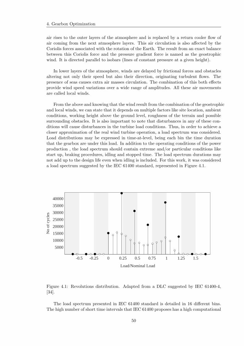
4. Gearbox Optimization
air rises to the outer layers of the atmosphere and is replaced by a return cooler flow ofair coming from the next atmosphere layers. This air circulation is also affected by theCoriolis forces associated with the rotation of the Earth. The result from an exact balancebetween this Coriolis force and the pressure gradient force is named as the geostrophicwind. It is directed parallel to isobars (lines of constant pressure at a given height).
In lower layers of the atmosphere, winds are delayed by frictional forces and obstaclesaltering not only their speed but also their direction, originating turbulent flows. Thepresence of seas causes extra air masses circulation. The combination of this both effectsprovide wind speed variations over a wide range of amplitudes. All these air movementsare called local winds.
From the above and knowing that the wind result from the combination of the geostrophicand local winds, we can state that it depends on multiple factors like site location, ambientconditions, working height above the ground level, roughness of the terrain and possiblesurrounding obstacles. It is also important to note that disturbances in any of these con-ditions will cause disturbances in the turbine load conditions. Thus, in order to achieve acloser approximation of the real wind turbine operation, a load spectrum was considered.Load distributions may be expressed in time-at-level, being each bin the time durationthat the gearbox are under this load. In addition to the operating conditions of the powerproduction , the load spectrum should contain extreme and/or particular conditions likestart up, braking procedures, idling and stopped time. The load spectrum durations maynot add up to the design life even when idling is included. For this work, it was considereda load spectrum suggested by the IEC 61400 standard, represented in Figure 4.1.
-0.5 -0.25 0 0.25 0.5 0.75 1 1.25 1.5
Load/Nominal Load
5000
10000
15000
20000
25000
30000
35000
40000
No
of c
ycle
s
Figure 4.1: Revolutions distribution. Adapted from a DLC suggested by IEC 61400-4,[34].
The load spectrum presented in IEC 61400 standard is detailed in 16 different bins.The high number of short time intervals that IEC 61400 proposes has a high computational
50
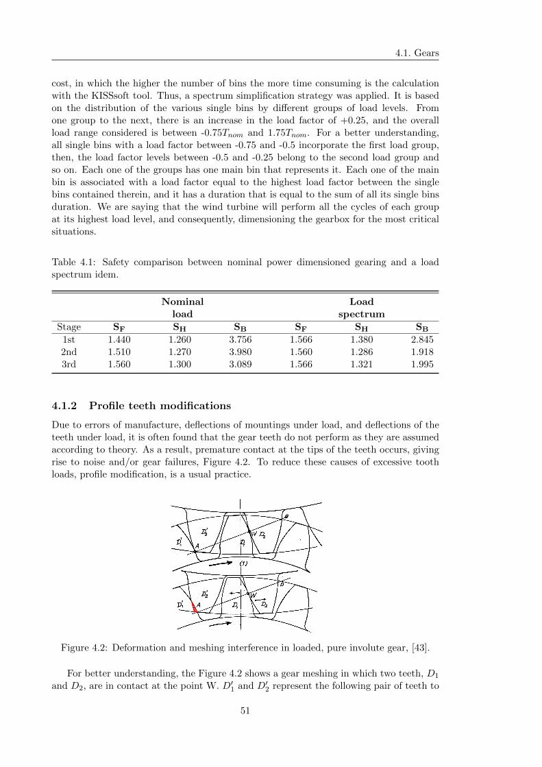
4.1. Gears
cost, in which the higher the number of bins the more time consuming is the calculationwith the KISSsoft tool. Thus, a spectrum simplification strategy was applied. It is basedon the distribution of the various single bins by different groups of load levels. Fromone group to the next, there is an increase in the load factor of +0.25, and the overallload range considered is between -0.75Tnom and 1.75Tnom. For a better understanding,all single bins with a load factor between -0.75 and -0.5 incorporate the first load group,then, the load factor levels between -0.5 and -0.25 belong to the second load group andso on. Each one of the groups has one main bin that represents it. Each one of the mainbin is associated with a load factor equal to the highest load factor between the singlebins contained therein, and it has a duration that is equal to the sum of all its single binsduration. We are saying that the wind turbine will perform all the cycles of each groupat its highest load level, and consequently, dimensioning the gearbox for the most criticalsituations.
Table 4.1: Safety comparison between nominal power dimensioned gearing and a loadspectrum idem.
Nominal Loadload spectrum
Stage SF SH SB SF SH SB
1st 1.440 1.260 3.756 1.566 1.380 2.8452nd 1.510 1.270 3.980 1.560 1.286 1.9183rd 1.560 1.300 3.089 1.566 1.321 1.995
4.1.2 Profile teeth modifications
Due to errors of manufacture, deflections of mountings under load, and deflections of theteeth under load, it is often found that the gear teeth do not perform as they are assumedaccording to theory. As a result, premature contact at the tips of the teeth occurs, givingrise to noise and/or gear failures, Figure 4.2. To reduce these causes of excessive toothloads, profile modification, is a usual practice.
Figure 4.2: Deformation and meshing interference in loaded, pure involute gear, [43].
For better understanding, the Figure 4.2 shows a gear meshing in which two teeth, D1
and D2, are in contact at the point W. D′1 and D′2 represent the following pair of teeth to
51
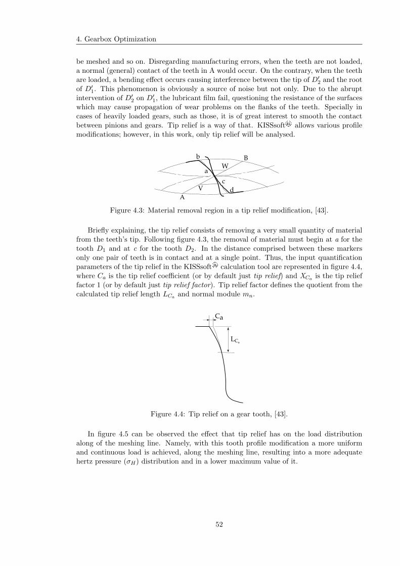
4. Gearbox Optimization
be meshed and so on. Disregarding manufacturing errors, when the teeth are not loaded,a normal (general) contact of the teeth in A would occur. On the contrary, when the teethare loaded, a bending effect occurs causing interference between the tip of D′2 and the rootof D′1. This phenomenon is obviously a source of noise but not only. Due to the abruptintervention of D′2 on D′1, the lubricant film fail, questioning the resistance of the surfaceswhich may cause propagation of wear problems on the flanks of the teeth. Specially incases of heavily loaded gears, such as those, it is of great interest to smooth the contactbetween pinions and gears. Tip relief is a way of that. KISSsoft® allows various profilemodifications; however, in this work, only tip relief will be analysed.
b
a
B
A
V d
c
W
Figure 4.3: Material removal region in a tip relief modification, [43].
Briefly explaining, the tip relief consists of removing a very small quantity of materialfrom the teeth’s tip. Following figure 4.3, the removal of material must begin at a for thetooth D1 and at c for the tooth D2. In the distance comprised between these markersonly one pair of teeth is in contact and at a single point. Thus, the input quantificationparameters of the tip relief in the KISSsoft® calculation tool are represented in figure 4.4,where Ca is the tip relief coefficient (or by default just tip relief) and XCa is the tip relieffactor 1 (or by default just tip relief factor). Tip relief factor defines the quotient from thecalculated tip relief length LCa and normal module mn.
Ca
LCa
Figure 4.4: Tip relief on a gear tooth, [43].
In figure 4.5 can be observed the effect that tip relief has on the load distributionalong of the meshing line. Namely, with this tooth profile modification a more uniformand continuous load is achieved, along the meshing line, resulting into a more adequatehertz pressure (σH) distribution and in a lower maximum value of it.
52
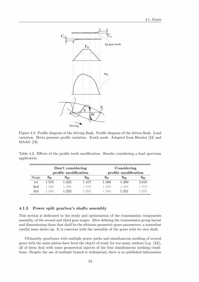
4.1. Gears
Ca
AV
W
E
�H
FNtip gear tooth
Driving
Ca
Figure 4.5: Profile diagram of the driving flank. Profile diagram of the driven flank. Loadvariation. Hertz pressure profile variation. Tooth mesh. Adapted from Henriot [43] andMAAG [19].
Table 4.2: Effects of the profile teeth modification. Results considering a load spectrumapplication.
Don’t considering Consideringprofile modification profile modification
Stage SF SH SB SF SH SB
1st 1.555 1.323 1.457 1.566 1.380 2.8452nd 1.560 1.286 1.918 1.560 1.286 1.9183rd 1.566 1.232 1.995 1.566 1.321 1.995
4.1.3 Power split gearbox’s shafts assembly
This section is dedicated to the study and optimization of the transmission componentsassembly, of the second and third gear stages. After defining the transmission group layoutand dimensioning those that shall be the ultimate geometric gears parameters, a somewhatcareful issue shows up. It is concerns with the assembly of the gears with its own shaft.
Ultimately, gearboxes with multiple power paths and simultaneous meshing of severalgears with the same pinion have been the object of study for too many authors (e.g. [44]),all of them deal with some geometrical aspects of the four simultaneous meshing condi-tions. Despite the use of multiple branch is widespread, there is no published information
53
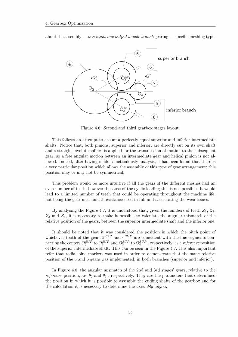
4. Gearbox Optimization
about the assembly — one input-one output double branch gearing — specific meshing type.
4
O2
O3
5
6
7
5
6
O4
SUP
O3INF
inferior branch
superior branch
a2SUP a3
SUP
Figure 4.6: Second and third gearbox stages layout.
This follows an attempt to ensure a perfectly equal superior and inferior intermediateshafts. Notice that, both pinions, superior and inferior, are directly cut on its own shaftand a straight involute splines is applied for the transmission of motion to the subsequentgear, so a free angular motion between an intermediate gear and helical pinion is not al-lowed. Indeed, after having made a meticulously analysis, it has been found that there isa very particular position which allows the assembly of this type of gear arrangement; thisposition may or may not be symmetrical.
This problem would be more intuitive if all the gears of the different meshes had aneven number of teeth; however, because of the cyclic loading this is not possible. It wouldlead to a limited number of teeth that could be operating throughout the machine life,not being the gear mechanical resistance used in full and accelerating the wear issues.
By analysing the Figure 4.7, it is understood that, given the numbers of teeth Z1, Z2,Z3 and Z4, it is necessary to make it possible to calculate the angular mismatch of therelative position of the gears, between the superior intermediate shaft and the inferior one.
It should be noted that it was considered the position in which the pitch point ofwhichever tooth of the gears 5SUP and 6SUP are coincident with the line segments con-necting the centers OSUP2 to OSUP3 and OSUP3 to OSUP4 , respectively, as a reference positionof the superior intermediate shaft. This can be seen in the Figure 4.7. It is also importantrefer that radial blue markers was used in order to demonstrate that the same relativeposition of the 5 and 6 gears was implemented, in both branches (superior and inferior).
In Figure 4.8, the angular mismatch of the 2nd and 3rd stages’ gears, relative to thereference position, are θ2 and θ3 , respectively. They are the parameters that determinedthe position in which it is possible to assemble the ending shafts of the gearbox and forthe calculation it is necessary to determine the assembly angles.
54

4.1. Gears
4
5
6
7
5
6
Figure 4.7: Reference positioning of seconf and third gear stages. Both intermediate pinionand gear are positioned exactly on the same orientation.
55

4.
Gearb
oxO
ptim
izatio
n
pitch point
pitch point
a2INF
a2SUP
pitchpointline
a3INF
a3INF
�
2�
��
�
2�
�2
�2
�
�+�2
�3
�3
46
5
7
Figure 4.8: Second and third gearbox stages assembly parameters.
56
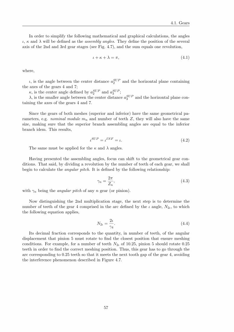
4.1. Gears
In order to simplify the following mathematical and graphical calculations, the anglesι, κ and λ will be defined as the assembly angles. They define the position of the severalaxis of the 2nd and 3rd gear stages (see Fig. 4.7), and the sum equals one revolution,
ι+ κ+ λ = π, (4.1)
where,
ι, is the angle between the center distance aSUP2 and the horizontal plane containingthe axes of the gears 4 and 7;
κ, is the center angle defined by aSUP2 and aSUP3 ;λ, is the smaller angle between the center distance aSUP3 and the horizontal plane con-
taining the axes of the gears 4 and 7.
Since the gears of both meshes (superior and inferior) have the same geometrical pa-rameters, e.g. nominal module mn and number of teeth Z, they will also have the samesize, making sure that the superior branch assembling angles are equal to the inferiorbranch idem. This results,
ιSUP = ιINF = ι. (4.2)
The same must be applied for the κ and λ angles.
Having presented the assembling angles, focus can shift to the geometrical gear con-ditions. That said, by dividing a revolution by the number of teeth of each gear, we shallbegin to calculate the angular pitch. It is defined by the following relationship:
γn =2π
Zn, (4.3)
with γn being the angular pitch of any n gear (or pinion).
Now distinguishing the 2nd multiplication stage, the next step is to determine thenumber of teeth of the gear 4 comprised in the arc defined by the ι angle, N2ι, to whichthe following equation applies,
N2ι =2ι
γ4. (4.4)
Its decimal fraction corresponds to the quantity, in number of teeth, of the angulardisplacement that pinion 5 must rotate to find the closest position that ensure meshingconditions. For example, for a number of teeth N2ι of 10.25, pinion 5 should rotate 0.25teeth in order to find the correct meshing position. Thus, this gear has to go through thearc corresponding to 0.25 teeth so that it meets the next tooth gap of the gear 4, avoidingthe interference phenomenon described in Figure 4.7.
57
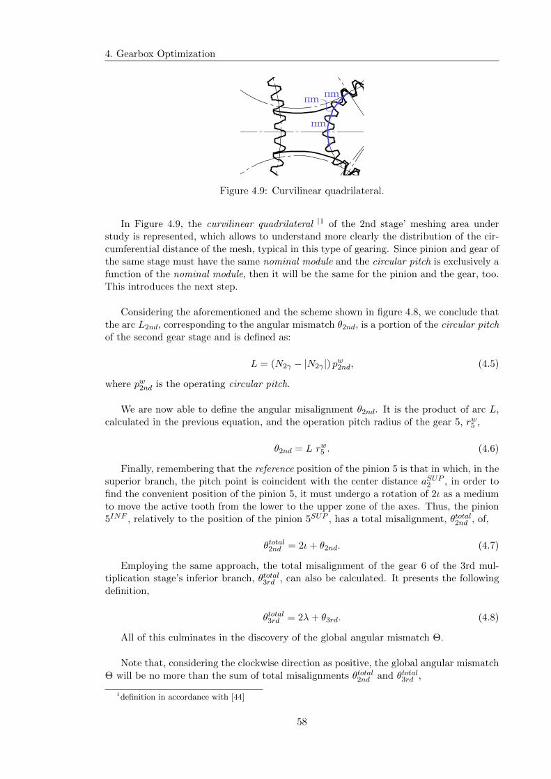
4. Gearbox Optimization
πm
πmπm
Figure 4.9: Curvilinear quadrilateral.
In Figure 4.9, the curvilinear quadrilateral |1 of the 2nd stage’ meshing area understudy is represented, which allows to understand more clearly the distribution of the cir-cumferential distance of the mesh, typical in this type of gearing. Since pinion and gear ofthe same stage must have the same nominal module and the circular pitch is exclusively afunction of the nominal module, then it will be the same for the pinion and the gear, too.This introduces the next step.
Considering the aforementioned and the scheme shown in figure 4.8, we conclude thatthe arc L2nd, corresponding to the angular mismatch θ2nd, is a portion of the circular pitchof the second gear stage and is defined as:
L = (N2γ − |N2γ |) pw2nd, (4.5)
where pw2nd is the operating circular pitch.
We are now able to define the angular misalignment θ2nd. It is the product of arc L,calculated in the previous equation, and the operation pitch radius of the gear 5, rw5 ,
θ2nd = L rw5 . (4.6)
Finally, remembering that the reference position of the pinion 5 is that in which, in thesuperior branch, the pitch point is coincident with the center distance aSUP2 , in order tofind the convenient position of the pinion 5, it must undergo a rotation of 2ι as a mediumto move the active tooth from the lower to the upper zone of the axes. Thus, the pinion5INF , relatively to the position of the pinion 5SUP , has a total misalignment, θtotal2nd , of,
θtotal2nd = 2ι+ θ2nd. (4.7)
Employing the same approach, the total misalignment of the gear 6 of the 3rd mul-tiplication stage’s inferior branch, θtotal3rd , can also be calculated. It presents the followingdefinition,
θtotal3rd = 2λ+ θ3rd. (4.8)
All of this culminates in the discovery of the global angular mismatch Θ.
Note that, considering the clockwise direction as positive, the global angular mismatchΘ will be no more than the sum of total misalignments θtotal2nd and θtotal3rd ,
1definition in accordance with [44]
58
4.2. Shafts
Θ = θtotal2nd + θtotal3rd . (4.9)
in which for both of them, the plus sign indicates a clockwise rotation and vice versa.
4.2 Shafts
Transmission shafts, or typically just shafts, are used virtually in every piece of rotatingmachinery to transmit rotary motion and torque from location to another, [45]. This is,just like in this project, shafts typically carry gears transmitting the rotary motion viameshing gear and consequently multiple stresses are led to the shaft. The loading on ro-tating transmission shafts is principally one of two types: torsion due to the transmittedtorque or bending from transverse loads at gears.
These two loads often act in combination. They can be steady (constant) or may varywith time. In the context of this work, this gearbox is faced with a situation of steadytorsion stress and alternating bending ones. So, considering an infinitesimal element ofthe shaft, it will always be affected of the same torque in any position, during the rotationcharacteristic of the mechanism operation. In contrast, although the steady transverseload, the same stress element on the shaft surface will be affected by a fully reversedbending stress. This happens because the forces associated with the contact of the teeth,during the meshing gear, cause a transverse deformation in the shaft which, due to itsrotational motion, will vary between a maximum and a minimum value. So, the infinites-imal elements go from tension to compression each cycle as the shaft turns. It should alsobe noted that due to the use of helical teeth a constant axial force is also transmitted tothe shaft. This combined effect of stresses points us to the problem to which this sectionis devoted: the fatigue failure.
Fatigue is defined as a phenomenon of progressive damage of materials subject to cyclicvariation of stress or deformation. The study of the phenomenon is of crucial importancein the design of machines and structures, since the great majority of the failures observed,during operation, involve the fatigue effect. Among the components subjected to repeatedloading and unloading, the gearbox’ shafts stand out. They are under a alternating bend-ing stresses caused by the cyclical motion characteristic of their rotation. Although thereis an analysis of the static load, in this type of cyclical motion it is insufficient becausematerials tend to have a lower resistance when under repeated loading and unloading.
This issue follows the optimization of the shaft so that it can correctly house and locatecomponents such as rolling bearings. In other words, in the previous chapter, the shaftsconsidered were just metal cylinders in order to simplify the comparison. However, realgearbox shafts are not that simple, it commonly require features such steps or shoulderswere the diameter changes to accommodate attached elements such as gears and rollingbearings. That features are necessary to provide accurate and consistent axial location ofthe attached elements avoiding them to slide along the shaft for example. Other generalfeatures are the keyslots for key joints or even retaining rings. Although the fatigue mech-anism has different successive phases, its beginning usually occurs in the surface, sincein general it is where the effect of the eventual stress concentrations,which are result ofthe previous discontinuities, is maximum. It should be the main objective to reduce thesesurface stress concentrations without correct assembly and operation being changed or
59

4. Gearbox Optimization
suppressed.
There are several ways to achieve this, one of them is, in the sections where the shaftdiameter varies, consider a gradual decrease of the dimension through the match radiususage; however, this solution is sometimes inadequate. It should be noted that for matingparts that do not have relatively large counterbore, the application of this mechanism canhinder total and correct contact between the components. Because of this, circumferentialcuts were used with different shapes of sections, adapted to each of the situations. Insuch a particular cases, relief groove was applied. It can broadly be defined as a clearancegroove of specified form and dimensions created by removing material at an inner cornerof a rotationally symmetric workpiece.
Following [46], the FKM guideline for analytical strength assessment of mechanicalcomponents has gained an increasing interest for the last decade in the industry, becauseit describes a general procedure directly applicable in an industrial design office. It allowsin particular a sound interpretation of finite element analysis, making an efficient bridgebetween stress results and a trustworthy safety margin. For that reason, it was the methodconsidered for the shaft calculation.
4.2.1 Assessment of the fatigue strength using nominal stresses: generalsafety factors
Starting with the fatigue dimensioning coefficients, the FKM standard was followed [47].According to this, in general, the safety factor consists of partial safety factors with regardto the load and to the material,
j = jS + jF , (4.10)
where, j is the safety factor; jS is the load factor; and jF is the material factor.
It considered that safety factors are valid on the condition that the characteristicsstrength values exhibit an average probability of survival of 97.5 percent. And, in theseconditions, the jS factor applied can be,
jS = 1.0, (4.11)
which was the one considered.
For non-welded components, the material safety factor for fatigue strength depends onthe possibilities of inspections and the consequences of failure is presented in the followingtable.
After that, and considering the previous table, a 1.35 jF factor was chosen.
4.2.2 Assessment of the fatigue strength using nominal stresses: indi-vidual safety factors
The safety factors used for the assessment of the static strength have different values,depending on the probability of the occurrence of the highest stress or the most unfavorable
60
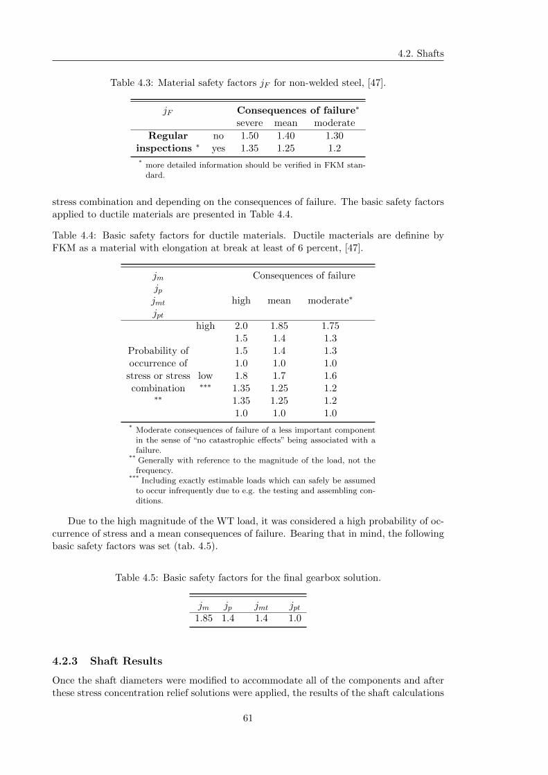
4.2. Shafts
Table 4.3: Material safety factors jF for non-welded steel, [47].
jF Consequences of failure∗
severe mean moderate
Regular no 1.50 1.40 1.30inspections ∗ yes 1.35 1.25 1.2
* more detailed information should be verified in FKM stan-dard.
stress combination and depending on the consequences of failure. The basic safety factorsapplied to ductile materials are presented in Table 4.4.
Table 4.4: Basic safety factors for ductile materials. Ductile macterials are definine byFKM as a material with elongation at break at least of 6 percent, [47].
jm Consequences of failurejpjmt high mean moderate∗
jpthigh 2.0 1.85 1.75
1.5 1.4 1.3Probability of 1.5 1.4 1.3occurrence of 1.0 1.0 1.0
stress or stress low 1.8 1.7 1.6combination ∗∗∗ 1.35 1.25 1.2
∗∗ 1.35 1.25 1.21.0 1.0 1.0
* Moderate consequences of failure of a less important componentin the sense of “no catastrophic effects” being associated with afailure.
** Generally with reference to the magnitude of the load, not thefrequency.
*** Including exactly estimable loads which can safely be assumedto occur infrequently due to e.g. the testing and assembling con-ditions.
Due to the high magnitude of the WT load, it was considered a high probability of oc-currence of stress and a mean consequences of failure. Bearing that in mind, the followingbasic safety factors was set (tab. 4.5).
Table 4.5: Basic safety factors for the final gearbox solution.
jm jp jmt jpt1.85 1.4 1.4 1.0
4.2.3 Shaft Results
Once the shaft diameters were modified to accommodate all of the components and afterthese stress concentration relief solutions were applied, the results of the shaft calculations
61
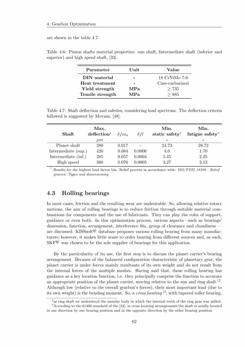
4. Gearbox Optimization
are shown in the table 4.7.
Table 4.6: Pinion shafts material properties: sun shaft, Intermediate shaft (inferior andsuperior) and high speed shaft, [33].
Parameter Unit Value
DIN material - 18 CrNiMo 7-6Heat treatment - Case-carburizedYield strength MPa ≥ 735
Tensile strength MPa ≥ 885
Table 4.7: Shaft deflection and safeties, considering load spectrum. The deflection criteriafollowed is suggested by Movnin, [48].
Max. Min. Min.Shaft deflection∗ δ/mn δ/l static safety∗ fatigue safety∗
µm - -
Planet shaft 280 0.017 - 24.73 28.72Intermediate (sup.) 420 0.084 0.0006 4.0 1.70Intermediate (inf.) 285 0.057 0.0004 5.45 2.25
High speed 380 0.076 0.0005 3.27 2.13
* Results for the highest load factor bin. Relief grooves in accordance with: ISO/FDIS 18388 - Reliefgrooves: Types and dimensioning.
4.3 Rolling bearings
In most cases, friction and the resulting wear are undesirable. So, allowing relative rotarymotions, the aim of rolling bearings is to reduce friction through suitable material com-binations for components and the use of lubricants. They can play the roles of support,guidance or even both. In this optimization process, various aspects—such as bearings’dimension, function, arrangement, interference fits, group of clearance and cleanliness —are discussed. KISSsoft® database proposes various rolling bearing from many manufac-turers; however, it makes little sense to order bearing from different sources and, as such,SKF® was chosen to be the sole supplier of bearings for this application.
By the particularity of its use, the first step is to discuss the planet carrier’s bearingarrangement. Because of the balanced configuration characteristic of planetary gear, theplanet carrier is under forces mainly resultants of its own weight and do not result fromthe internal forces of the multiple meshes. Having said that, these rolling bearing hasguidance as a key location function, i.e. they principally comprise the function to accuratean appropriate position of the planet carrier, moving relative to the sun and ring shaft |2.Although low (relative to the overall gearbox’s forces), their most important load (due toits own weight) is the bending moment. So, a cross locating |3, with tapered roller bearing,
2as ring shaft we understood the annular body in which the internal teeth of the ring gear was milled.3According to the 61400 standard of the [34], in cross locating arrangements the shaft is axially located
in one direction by one bearing position and in the opposite direction by the other bearing position.
62
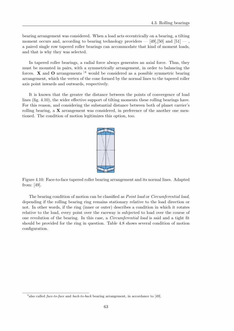
4.3. Rolling bearings
bearing arrangement was considered. When a load acts eccentrically on a bearing, a tiltingmoment occurs and, according to bearing technology providers — [49],[50] and [51] — ,a paired single row tapered roller bearings can accommodate that kind of moment loads,and that is why they was selected.
In tapered roller bearings, a radial force always generates an axial force. Thus, theymust be mounted in pairs, with a symmetrically arrangement, in order to balancing theforces. X and O arrangements |4 would be considered as a possible symmetric bearingarrangement, which the vertex of the cone formed by the normal lines to the tapered rolleraxis point inwards and outwards, respectively.
It is known that the greater the distance between the points of convergence of loadlines (fig. 4.10), the wider effective support of tilting moments these rolling bearings have.For this reason, and considering the substantial distance between both of planet carrier’srolling bearing, a X arrangement was considered, in preference of the another one men-tioned. The condition of motion legitimizes this option, too.
Figure 4.10: Face-to-face tapered roller bearing arrangement and its normal lines. Adaptedfrom: [49].
The bearing condition of motion can be classified as Point load or Circumferential load,depending if the rolling bearing ring remains stationary relative to the load direction ornot. In other words, if the ring (inner or outer) describes a condition in which it rotatesrelative to the load, every point over the raceway is subjected to load over the course ofone revolution of the bearing. In this case, a Circumferential load is said and a tight fitshould be provided for the ring in question. Table 4.8 shows several condition of motionconfiguration.
4also called face-to-face and back-to-back bearing arrangement, in accordance to [49].
63
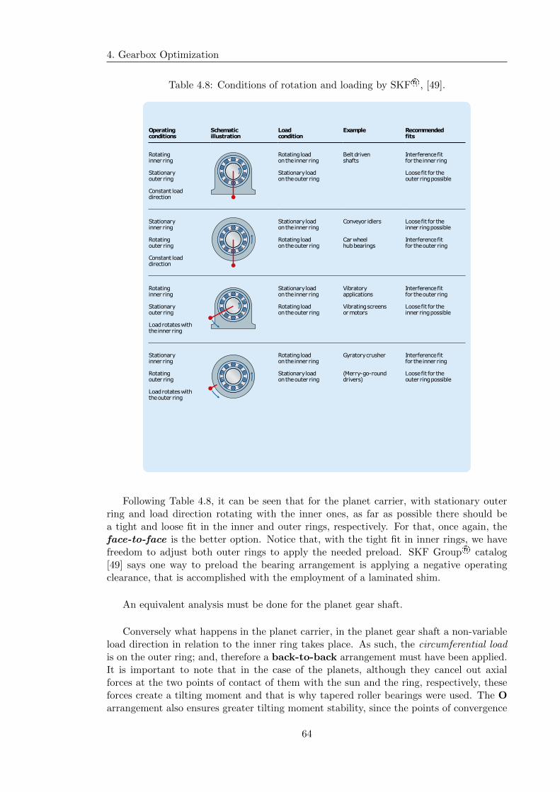
4. Gearbox Optimization
Table 4.8: Conditions of rotation and loading by SKF®, [49].
Operating conditions
Schematic illustration
Load condition
Example Recommended fits
Rotating inner ring
Rotating load on the inner ring
Belt driven shafts
Interference fit for the inner ring
Stationary outer ring
Stationary load on the outer ring
Loose fit for the outer ring possible
Constant load direction
Stationary inner ring
Stationary load on the inner ring
Conveyor idlers Loose fit for the inner ring possible
Rotating outer ring
Rotating load on the outer ring
Car wheel hub bearings
Interference fit for the outer ring
Constant load direction
Rotating inner ring
Stationary load on the inner ring
Vibratory applications
Interference fit for the outer ring
Stationary outer ring
Rotating load on the outer ring
Vibrating screens or motors
Loose fit for the inner ring possible
Load rotates with the inner ring
Stationary inner ring
Rotating load on the inner ring
Gyratory crusher Interference fit for the inner ring
Rotating outer ring
Stationary load on the outer ring
(Merry-go-round drivers)
Loose fit for the outer ring possible
Load rotates with the outer ring
Following Table 4.8, it can be seen that for the planet carrier, with stationary outerring and load direction rotating with the inner ones, as far as possible there should bea tight and loose fit in the inner and outer rings, respectively. For that, once again, theface-to-face is the better option. Notice that, with the tight fit in inner rings, we havefreedom to adjust both outer rings to apply the needed preload. SKF Group® catalog[49] says one way to preload the bearing arrangement is applying a negative operatingclearance, that is accomplished with the employment of a laminated shim.
An equivalent analysis must be done for the planet gear shaft.
Conversely what happens in the planet carrier, in the planet gear shaft a non-variableload direction in relation to the inner ring takes place. As such, the circumferential loadis on the outer ring; and, therefore a back-to-back arrangement must have been applied.It is important to note that in the case of the planets, although they cancel out axialforces at the two points of contact of them with the sun and the ring, respectively, theseforces create a tilting moment and that is why tapered roller bearings were used. The Oarrangement also ensures greater tilting moment stability, since the points of convergence
64

4.3. Rolling bearings
of load lines are further apart than they would be in an X arrangement.
Regarding the sun shaft, because of the single helical planetary gear, it has high com-bined axial and radial loads; therefore, a combination with a radial and an axial forcescarrying rolling bearing has been selected. Assuming a locating and non-locating bear-ing arrangement for this shaft, since the locating function is already being performed bythe match of the radial and axial bearings, a non-locating bearing has to be found. Itshall provides radial support only, allowing axial displacements to accommodate shaftlength thermal variations. The one selected was the spherical roller bearings, this in ad-dition to allowing adaptability to the effects of thermal expansion, it also allows angularself-alignment which provides some freedom of flotation in the sun, adjusting this to themultiple teeth meshing with the different planet gears. This ensures a uniform distributionof power.
According to the Table 4.8, for a stationary outer ring a circumferential load on theinner ones is verified; then, a tight fit was applied on both inner rings of the cylindricalroller bearings and the axial ones.
For the intermediate bearings, special SKF Explorer bearing was selected. They aredesigned for applications such as gearboxes in wind turbines and others, [49]. It is knownthat bearings with a cage can accommodate heavy radial loads, and the maximum exampleof this are the full complement bearings. SKF® high-capacity cylindrical roller bearingscombine the high load carrying capacity of a full complement bearing with the high speedcapability of a bearing with a cage. Its window-type metal cage is designed so that its cagebars are displaced relative to the roller pitch diameter, enabling the rollers to be placedcloser to each other, creating room for addition all rollers. A NCF .. ECJB design waschosen. With an inner ring centred cage, they are used to locate the shaft axially in onedirection and eventually to accommodate axial displacement of the shaft relative to thehousing in the opposite direction; so, a symmetrically configuration must be applied inorder to accommodate shaft length thermal variations. Don’t should be forgotten that atwo cylindrical roller bearing can be considered, due to the cancel out of the axial load bythe double helical gears.
Finally, for the high speed shaft, some important details had to be analysed and opti-mized. With a relatively restricted outside diameter, because of the available gear centerdistance, a solution with a high radial load capacity (effect of the double branch withdouble helical gear) had to be found. It should be noted that, since the high speed gear isnot positioned at half of the shaftway, the rotor and generator side bearings will be underdifferent conditions of load, being last the most critical one. Although the tapered rollerbearings not being the first choice for the higher speed shaft of a gearbox, the output shaftof this WTG is supported at the two ends that are significantly spaced apart from thepoint of load application (the output pinion). This causes significant bending effects inthe supports, which are not compatible with the use of cylindrical roller bearings or evendeep groove ball bearings.
Thus, after testing several possibilities, the chosen configuration was: a cylindricalroller bearing and a paired single row tapered roller bearing on the rotor and on thegenerator side, respectively. This solution allows to distribute the load through the twobearings, without asking for a bigger rolling bearing.
65

4. Gearbox Optimization
Regarding bearing life calculations, instead of using the manufacturers formulas, as inthe previous chapter, a more accurate method was used, specified in ISO/TS 16281:2008and ISO 281:2007, which calculates bearing life considering the influence of several fac-tors such as lubricant contamination, filtration, shaft tilting and misalignment. Using thismethod, two new input parameters must be given: the filtration ration βx(c), with particlesize x in µm(c)4 according to ISO 16889, is the most influencing factor when selecting dia-grams and equations for circulating oil systems with on-line filters; and, the contaminationlevel, which corresponds mainly to the condition of the oil before it passes the on-line filter.Recommended values from IEC 61400-4 [34], were use to set this parameters. Accordingto them the steady state cleanliness level for a gearbox in constant operation shall not beworse than -/17/14, with a typical value of the beta ratio greater than or equal to 200.
It should be noted that tighter cleanliness values can be considered with the conse-quence of increasing costs. Nevertheless, the greater cleanliness values, the shorter thelifetimes for the bearings are expected, so we are working on the safety side.
Table 4.9: Bearing service lifetime and safety levels. Results considering the oil cleanlinesslevel ISO/TS 16281 [52] and the load spectrum.
Shaft Min. static Min. bearing Max.bearing safety service life pressure
- x 1000 hours MPa
Planet shaft 3.33 198 2 285Intermediate (sup.) 4.67 476 2 124Intermediate (inf.) 6.34 > 1000 1 888
High speed 9.60 > 1000 1 636
66
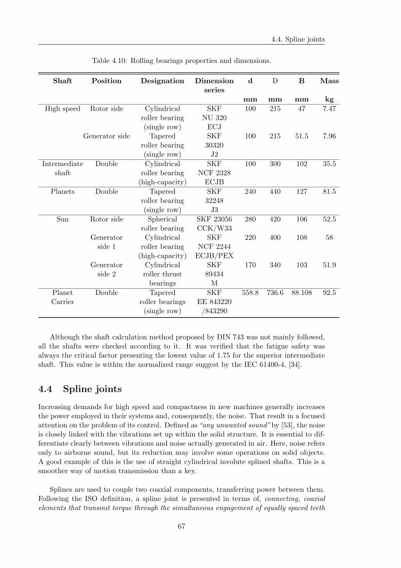
4.4. Spline joints
Table 4.10: Rolling bearings properties and dimensions.
Shaft Position Designation Dimension d D B Massseries
mm mm mm kg
High speed Rotor side Cylindrical SKF 100 215 47 7.47roller bearing NU 320(single row) ECJ
Generator side Tapered SKF 100 215 51.5 7.96roller bearing 30320(single row) J2
Intermediate Double Cylindrical SKF 100 300 102 35.5shaft roller bearing NCF 2328
(high-capacity) ECJB
Planets Double Tapered SKF 240 440 127 81.5roller bearing 32248(single row) J3
Sun Rotor side Spherical SKF 23056 280 420 106 52.5roller bearing CCK/W33
Generator Cylindrical SKF 220 400 108 58side 1 roller bearing NCF 2244
(high-capacity) ECJB/PEXGenerator Cylindrical SKF 170 340 103 51.9
side 2 roller thrust 89434bearings M
Planet Double Tapered SKF 558.8 736.6 88.108 92.5Carrier roller bearings EE 843220
(single row) /843290
Although the shaft calculation method proposed by DIN 743 was not mainly followed,all the shafts were checked according to it. It was verified that the fatigue safety wasalways the critical factor presenting the lowest value of 1.75 for the superior intermediateshaft. This value is within the normalized range suggest by the IEC 61400-4, [34].
4.4 Spline joints
Increasing demands for high speed and compactness in new machines generally increasesthe power employed in their systems and, consequently, the noise. That result in a focusedattention on the problem of its control. Defined as “any unwanted sound” by [53], the noiseis closely linked with the vibrations set up within the solid structure. It is essential to dif-ferentiate clearly between vibrations and noise actually generated in air. Here, noise refersonly to airborne sound, but its reduction may involve some operations on solid objects.A good example of this is the use of straight cylindrical involute splined shafts. This is asmoother way of motion transmission than a key.
Splines are used to couple two coaxial components, transferring power between them.Following the ISO definition, a spline joint is presented in terms of, connecting, coaxialelements that transmit torque through the simultaneous engagement of equally spaced teeth
67

4. Gearbox Optimization
situated around the periphery of a cylindrical external member with similar spaced mat-ing spaces situated around the inner surface of the related cylindrical internal member [54].
In the context of this thesis, they have the function of replacing the action of a key inthe transmission of torque from the shafts to the multiple gears. According to [55], theuse of splines is the best solution whenever large amounts of torque to be transmitted.Although splines resemble gear teeth and are cut with the equivalent tools, their action issomewhat different, in terms that, (with spline) the teeth all fit together.
This leads us to choose the type of interference fit for the spline teeth. Three typesof fits ate illustrated in Figure 4.11. In flank-centred connections, the flanks of the teethserve to transmit the forces as well as to centre the parts, and that is why this type offit was chosen. In fact, in this application a large amount of power is needed to trans-mit, using the flanks area to its transferring, a more active area will be consider and aless concentration of load shall be applied. Also, with the diameter-centred fitted splinedconnections, a over-determination of the centering needs to be prevented with the choseof enough backlash. A loose choice of it could compromise the correct transmission ofmotion, since the contact between the shaft and the hub was not verified.
Figure 4.11: Example of spline fits, [55].
The ISO 4156 standard [54] list three standards for involute splines, depending uponthe nominal pressure angle employed are 30° ,37.5°|5 and 40°. The 30 ° pressure was se-lected, it is most often used when the two members are allowed to slide. Note that due tothe use of the double helix it is necessary the gear to be able to slid freely along the shaftso that it can self-center with its own pinion, balancing the load. It can be also referredthat higher pressure angles normally use large number of teeth, which makes the cuttingprocess time-consuming.
The external and internal diameters always have clearance and do not contact eachother, Fig. 4.12, i. e. the diameters of the tip and root circles of the shaft differ from therespective diameters of the hub and the exact dimensions can be consulted in the secondpart of the ISO 4156 standard, [56].
5For electronic data processing purposes, the form of expression 37.5° has been adopted instead of 37°30’
68
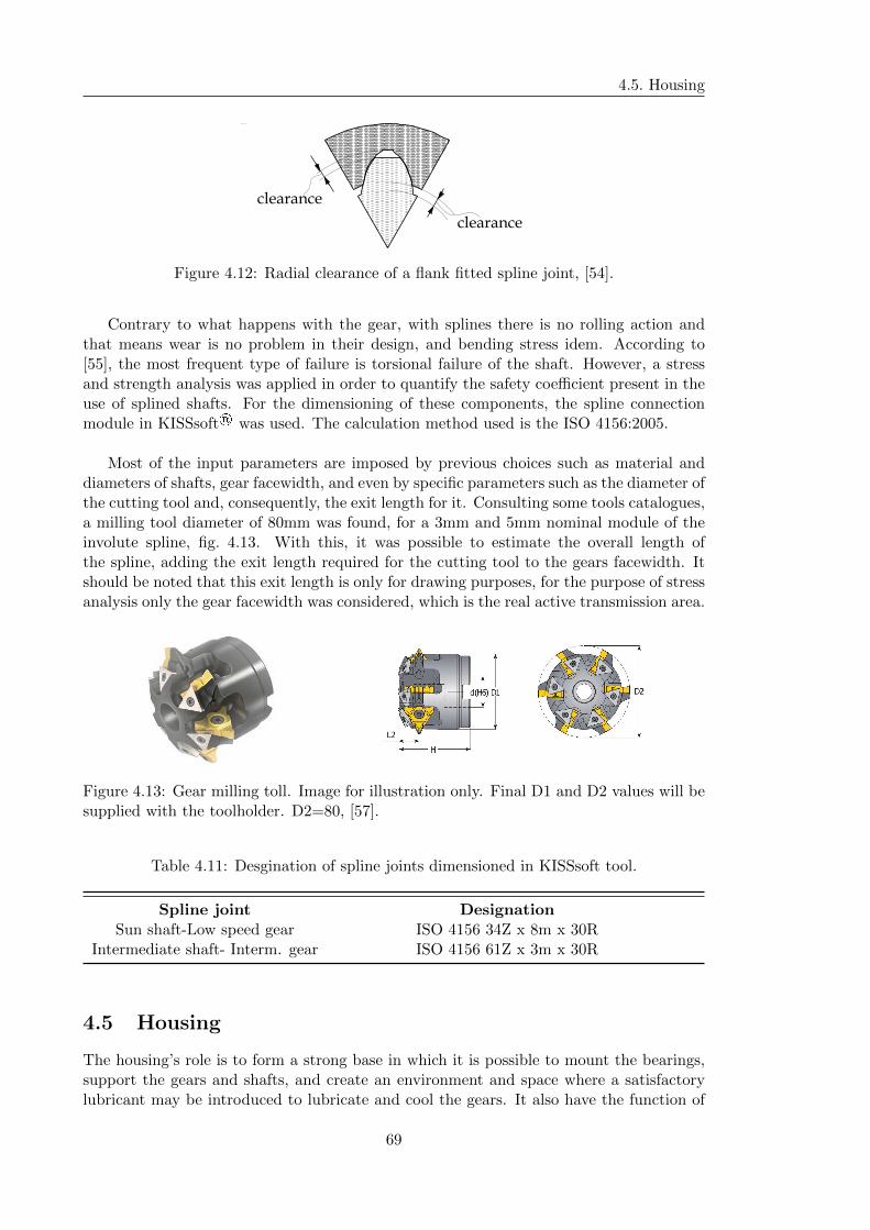
4.5. Housing
clearance
clearance
Figure 4.12: Radial clearance of a flank fitted spline joint, [54].
Contrary to what happens with the gear, with splines there is no rolling action andthat means wear is no problem in their design, and bending stress idem. According to[55], the most frequent type of failure is torsional failure of the shaft. However, a stressand strength analysis was applied in order to quantify the safety coefficient present in theuse of splined shafts. For the dimensioning of these components, the spline connectionmodule in KISSsoft® was used. The calculation method used is the ISO 4156:2005.
Most of the input parameters are imposed by previous choices such as material anddiameters of shafts, gear facewidth, and even by specific parameters such as the diameter ofthe cutting tool and, consequently, the exit length for it. Consulting some tools catalogues,a milling tool diameter of 80mm was found, for a 3mm and 5mm nominal module of theinvolute spline, fig. 4.13. With this, it was possible to estimate the overall length ofthe spline, adding the exit length required for the cutting tool to the gears facewidth. Itshould be noted that this exit length is only for drawing purposes, for the purpose of stressanalysis only the gear facewidth was considered, which is the real active transmission area.
D1
H
d(H6)
L2
D2
Figure 4.13: Gear milling toll. Image for illustration only. Final D1 and D2 values will besupplied with the toolholder. D2=80, [57].
Table 4.11: Desgination of spline joints dimensioned in KISSsoft tool.
Spline joint DesignationSun shaft-Low speed gear ISO 4156 34Z x 8m x 30R
Intermediate shaft- Interm. gear ISO 4156 61Z x 3m x 30R
4.5 Housing
The housing’s role is to form a strong base in which it is possible to mount the bearings,support the gears and shafts, and create an environment and space where a satisfactorylubricant may be introduced to lubricate and cool the gears. It also have the function of
69

4. Gearbox Optimization
to house several other components such as accessories and parts near or common to thegearing.
The housing will be manufactured in a continuous casting process, so the design driverwas the use of round shapes. When round shapes weren’t possible to apply, a tilt anglebetween the mentioned surface and the exit direction of the part was considered. Thisessentially occurs in main (input and output) lids, fig. 4.14.
Figure 4.14: Tilting angle of main lid (generator side) surface, [57].
It will be seen, in a general race, the housing is formed by:
� a main body;
� a main input lid;
� a main outlet lid;
� five inspection covers;
� four secondary external covers;
� three secondary internal covers;
The main body was thought to be robust so that it can to prevent excessive distor-tions resulting from thermal variations, mechanical loading, or both. It has a pivotal wallseparating the two parts of the gearbox — the planetary stage and the remainder twowith power split. For the correct operation of the mechanism it was not needed to dividethe two parts of the gearbox, however due to a matter of compactness it was necessaryto create several supporting points for different rolling bearings, namely matched taperedroller bearings of the sun shaft and cylindrical roller bearing of the intermediate and highspeed shafts, which are positioned on the rotor side. It should be noted that the mainbody is also responsible for the transition from the circular section of the ring gear rim tothe second and third stages’ double branch configuration.
The main lids, input and output, have the function of providing split planes for gearmounting and dismounting. The alignment of each lid with the main body is allowed bythe application of tapered dowel pins and it shall be employed a flat metal-to-metal jointmaintained oil tight with suitable sealing compound. Both lids have multiple removableinspection covers for field inspection of the full facewidth of all gear meshes. By recom-mendation of [15], the tapped holes for the bolts of the inspection covers should be blind.Because of the configuration of the planetary stage it may be difficult to inspect the gearsand, for that, borescopes using fiber optics can be used to inspect them. Particular atten-tion should be paid to the fact that the input lid contains supporting torque arm to prevent
70

4.6. Other components
the housing from rotating. The configuration chosen for them design was an attempt ofrobustness and versatility, in that several points can be used for the gearbox attachment.However, there is an entire analysis of its dynamic behavior that must be done, allowinga complete study of the stiffness’ gearbox foundation. This was not possible to performas it would require a substantial amount of time for small improvements.
The secondary covers are all used for the fixing of rolling bearings and to provide lu-brication paths for their raceways. The external covers are coupled on the output lid. Itshould be also employed suitable sealing compound (like in the split plane of the mainbody) in the joint plane of the external secondary covers with the output lid.
For the last, the housing have internal and external lines of oil circulation, even thewalls place by on its own paths for the lubricating system. This will be carefully explainin ensuing sections.
Following [15], all gears should be totally enclosed in a cast ductile iron or cast steelhousing. So, it was selected the nodular cast iron GGG40, Table 4.12 .
Table 4.12: GGG40 mechanical properties, [33].
Yield strength Tensile strengthMPa Mpa
≥ 245 ≥ 392
4.6 Other components
4.6.1 Shaft seals
Retaining lubricant and preventing any contaminants from entering into a controlled en-vironment are the most general roles of the seals. Indeed, the propagation of particlesinside the gearbox would be a decisive factor for the operation of the components such asrolling bearings and gears. In addition of providing surface wear, their storage can creatsticky and adhesive sediments. The seals applied in this works were fully selected from [58].
The chosen seal designs are the BAUMX7 and Radiamatic R35 for the input andoutput shafts, respectively.
The BAUMX7, with a improved chemical resistance and thermal stability, is a reli-able seal even with increased thermal expansion. With a preferred usage for synthetic oilstemperature higher than 80 °C, it is a good choice for an oil injection of 65 °C. Notice that,for this inlet temperature it is expected a higher return temperature. The BAUMX7 sealsinclude a steel spring acting as a pretensioning element for the seal lip. The spring pro-vides a defined uniformly distributed contact, guaranteing a continuously sealing. A onlyone lip design allows a low friction solution, usable for circumferential speeds of 10 m/s ormore which is approximately the linear speed of the output shaft.
71

4. Gearbox Optimization
Figure 4.15: Radiamatic R35 shaft seal.
Although according to the chart provided by the manufacturer, presented in Fig-ure 4.16, the speed and diameter of the shaft suggest the use of NBR material, FKMmaterial was chosen. Since the seals are a low cost component, the price difference doesnot justify the choice of a less noble material. With this decision, we are always going toextend the safety of the mechanism.
40
30
20
10
5
0
15 000 10 000 90008000 7000 6000 5000 4500 4000
3500
3000
2500
2000
1500
1000
500
30000
0 25 50 100 150 200...500
FKM
NBR
Shaft diameter [mm]
Circ
umfe
rent
ial s
peed
[m/s
]
Speed [revs/min]
Figure 4.16: Circumferential speed allowed by NBR and FKM SIMRIT® shaft seal ma-terials.
According to [59], shafts seals rings with additional functions like Radiamatic R 55design with a deflector lip, are used to seal the main bearings in wind turbines. Consultingthe several catalogues we have found that there are no far information about its geometricand mechanical specifications. So, a Radiamatic R 35 in combination with a standardV-ring was chosen, Fig. 4.17. According to the same author, it is a often used solutionin this kind of application by substitution of R 55.
72
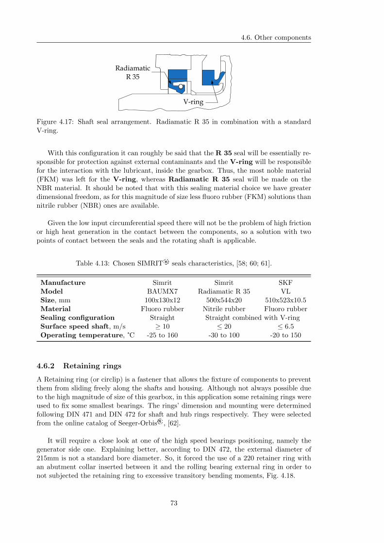
4.6. Other components
Radiamatic R 35
V-ring
Figure 4.17: Shaft seal arrangement. Radiamatic R 35 in combination with a standardV-ring.
With this configuration it can roughly be said that the R 35 seal will be essentially re-sponsible for protection against external contaminants and the V-ring will be responsiblefor the interaction with the lubricant, inside the gearbox. Thus, the most noble material(FKM) was left for the V-ring, whereas Radiamatic R 35 seal will be made on theNBR material. It should be noted that with this sealing material choice we have greaterdimensional freedom, as for this magnitude of size less fluoro rubber (FKM) solutions thannitrile rubber (NBR) ones are available.
Given the low input circumferential speed there will not be the problem of high frictionor high heat generation in the contact between the components, so a solution with twopoints of contact between the seals and the rotating shaft is applicable.
Table 4.13: Chosen SIMRIT® seals characteristics, [58; 60; 61].
Manufacture Simrit Simrit SKFModel BAUMX7 Radiamatic R 35 VLSize, mm 100x130x12 500x544x20 510x523x10.5Material Fluoro rubber Nitrile rubber Fluoro rubberSealing configuration Straight Straight combined with V-ringSurface speed shaft, m/s ≥ 10 ≤ 20 ≤ 6.5Operating temperature, °C -25 to 160 -30 to 100 -20 to 150
4.6.2 Retaining rings
A Retaining ring (or circlip) is a fastener that allows the fixture of components to preventthem from sliding freely along the shafts and housing. Although not always possible dueto the high magnitude of size of this gearbox, in this application some retaining rings wereused to fix some smallest bearings. The rings’ dimension and mounting were determinedfollowing DIN 471 and DIN 472 for shaft and hub rings respectively. They were selectedfrom the online catalog of Seeger-Orbis®, [62].
It will require a close look at one of the high speed bearings positioning, namely thegenerator side one. Explaining better, according to DIN 472, the external diameter of215mm is not a standard bore diameter. So, it forced the use of a 220 retainer ring withan abutment collar inserted between it and the rolling bearing external ring in order tonot subjected the retaining ring to excessive transitory bending moments, Fig. 4.18.
73
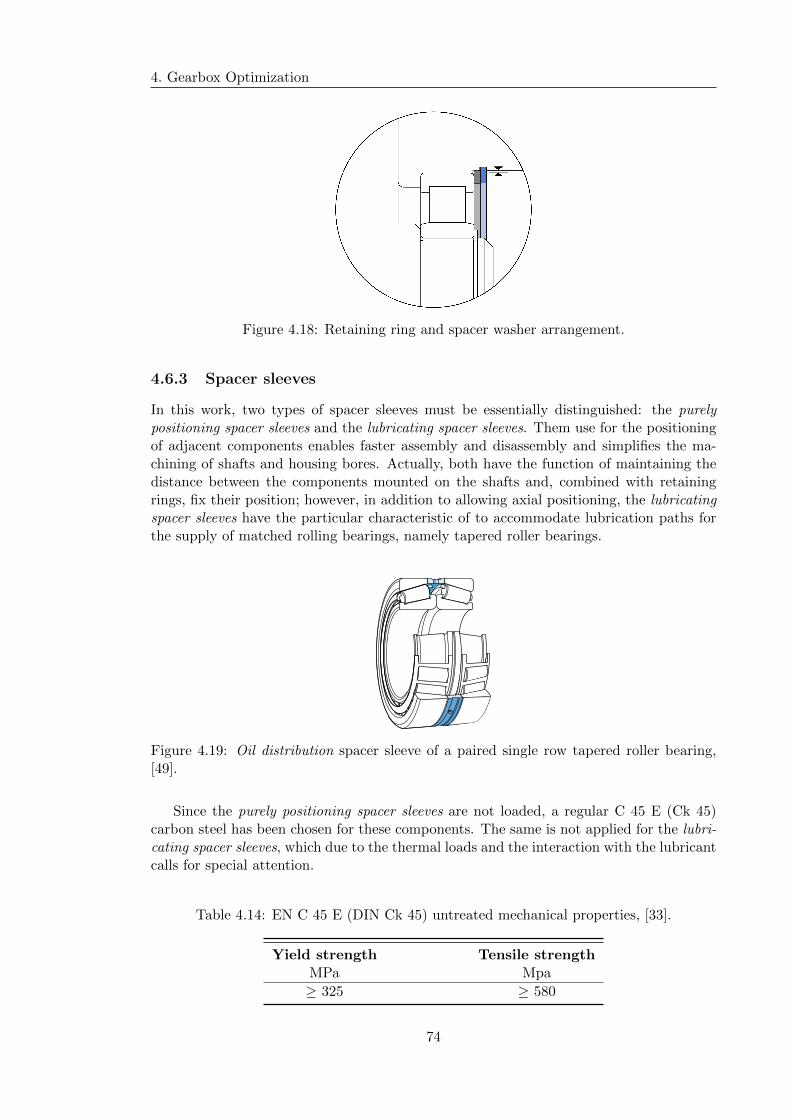
4. Gearbox Optimization
Figure 4.18: Retaining ring and spacer washer arrangement.
4.6.3 Spacer sleeves
In this work, two types of spacer sleeves must be essentially distinguished: the purelypositioning spacer sleeves and the lubricating spacer sleeves. Them use for the positioningof adjacent components enables faster assembly and disassembly and simplifies the ma-chining of shafts and housing bores. Actually, both have the function of maintaining thedistance between the components mounted on the shafts and, combined with retainingrings, fix their position; however, in addition to allowing axial positioning, the lubricatingspacer sleeves have the particular characteristic of to accommodate lubrication paths forthe supply of matched rolling bearings, namely tapered roller bearings.
Figure 4.19: Oil distribution spacer sleeve of a paired single row tapered roller bearing,[49].
Since the purely positioning spacer sleeves are not loaded, a regular C 45 E (Ck 45)carbon steel has been chosen for these components. The same is not applied for the lubri-cating spacer sleeves, which due to the thermal loads and the interaction with the lubricantcalls for special attention.
Table 4.14: EN C 45 E (DIN Ck 45) untreated mechanical properties, [33].
Yield strength Tensile strengthMPa Mpa
≥ 325 ≥ 580
74

4.6. Other components
The lubricants generally used for rolling bearings do not have a detrimental effect onspacer sleeves properties. Yet, with some synthetic oil base and lubricants containingEP additives, the mechanical integrity of certain materials can prove inadequate. Conse-quently, a non-alloyed structural E555 (St52.0) was chosen. It can be used at operatingtemperatures up to 300 °C and it isn’t affected by the synthetic oil-based lubricants, orby the organic solvents used to clean bearings, [33].
Table 4.15: EN E355 (DIN St52.0) mechanical properties, [33].
Yield strength Tensile strengthMPa Mpa
≥ 335 ≥ 490
At last, in order to be sure that the bearings are not “clamped”, adequate axial inter-nal clearance has been performed, between the lubricating spacer sleeve and its adjacentrolling bearing races. That is, when adjusting tapered roller bearings against each otherit is necessary to ensure that the rollers are able to rotate freely at their correct positionand an extra load is not being imposed by an oversized width of the spacer sleeves.
Figure 4.20: Internal axial clearance of a paired single row tapered roller bearing, [49].
75

4. Gearbox Optimization
76

Part III
77

Chapter 5
Lubrication system
5.1 Introduction
Our world, as we know, strongly depends on mechanical devices that are closely relatedwith lubrication issues. By other words, whether in our homes or at work, all of us aresurrounded and dependent on the mechanism that, for its proper functioning, requireslubricant films for both friction and heat dissipation issues. Like this, lubrication and theknowledge of lubricants no only are a subject of interest for us but they are also criticalto the cost effective operation and reliability of machinery that is part of our daily lives.This section builds upon the lubrication fundamentals that was followed for the lubricatingsystem design and dimensioning.
Knowing that the name petroleum is derived from the latin petra (rock) and oleum (oil),it is easy to conclude that it present in among rocks in the earth. keeping pace with thealwasys more demanding technology available, petroleum has been worked and combinedin various ways taking various forms and applications today. Lubricating oils for windturbine gearbox is one of them. As stated in the previous chapter, the lubricant chosenfor this project was the synthetic oil Castrol Optigear Synthetic X 320. Considerableattention has been focused on synthetic lubricants since the introduction into the retailmarket of synthetic-based engine oils and its application extends back over many years.Interests is synthetic lubricants were due to their ability to resist burning to a greaterdegree than mineral oils and to provide equipment protection advantages under extremesof operating conditions, [37]. In the context of this work, its advantage includes extendedservice, low temperature starting, high properties stability with temperature and broadtemperature application range.
Considering this application, the elements of machines that require lubrication aremainly gears and rolling bearings. These elements have fitted or formed surfaces thatmove with respect to each other by sliding, rolling, and advancing and receding, or bycombinations of these motions; thus, these elements must be lubricated to prevent or re-duce the actual contact between surfaces which may cause high frictional forces leadingto high temperatures, and possibly wear or failure. This is particularly important in thiswork since the expected lifetime of an wind turbine is about 20 years and, consequently,the same is expected of the gearbox. It should never be forgotten that in machines ofthis size the stopping times are considerable and therefore the cost of interrupting normaloperation for maintenance or replacement of components is very high. The implication ofmany stops increases the market price of the gearbox, which can lead to a lack of interest
79

5. Lubrication system
about the same.
Lubrication films may be classified in three main different kinds — fluid, thin or solid— but in this work it was only considered a fluid type of. With fluid films we have theenough thickness to ensure completely separation of the load carrying surfaces during theoperation. Despite of the drag effect of the lubricant that sometimes occurs, here it is apractical minimum as well as the wear theoretically does not occur because there is no me-chanical contact. Since a convergent zone exists immediately before these areas of contact,a lubricant will be drawn into a contact area and can form a hydrodynamic film, moreprecisely, an elastohydrodynamic film. That is typical of the contact between two differentgears that elastic deformation of the material occurs before the film can be formed. Assuch, this type of lubrication mode is a particular case of hydrodynamic lubrication beingawarded with the prefix “elasto”. It is common to use only the acronym EHD|1.
Gears have the function of transmitting power from one rotating shaft to another alongthe entire kinematic chain, from the input of the gearbox to its output. With respect tolubrication and the formation and maintenance of lubricating film, the gears can be clas-sified into several types — spur, bevel, helical, double helical, worm, and others — but inthis chapter only, as previous defined, helical and double helical gears it will be considered.As gear teeth mesh, they roll and slide together. In the progression of contact as a pairof gear, the first contact is between a point near the root of the driving tooth and a pointat the tip of the driven tooth. At this, the preceding teeth are still in mesh and carryingmost of the load. As the contact progresses, the teeth roll and slide on each other fromthis position to the position where two pairs of teeth are engaged so that the transitionof the load from the first to the next pair of teeth is made. Between these two positionsthe point of contact across through the particular position of the pitch point where thereis pure rolling and/or no sliding. Having said this, it can be concluded that sliding variesfrom a maximum velocity in one direction at the start of mesh, through zero velocity atthe pitch line, then again to a maximum velocity in the opposite direction at the ends ofmesh; this, at the same time that rolling is continuous and added to the previous slid effect.
As stated above, in the EHD lubrication the elastic deformation of the bodies in con-tact occurs so that the lubricant film is formed. As such, the points of contact extendinto a contact area. For abundant lubrication, as suggested in previous chapters, the oillubricant must be injected to the full extent of the gear facewidth in the initial meshingzone, so that the full coverage of that contact area is guaranteed. In the case of industrialgears, the teeth are loaded sufficiently to ensure a progressive elastic deformation of theteeth along the meshing line. So, a successive convergent zone exists, pushing the injectedoil from the beginning to the end of the engagement.
After understanding the formation of the fluid film in the convergent and after to beselected, in the previous Chapter 3, the most appropriate lubricant, it is necessary to un-cover the method of lubrication. Due to its applicability to this gearbox, it has alreadybeen shown that the injected lubrication was selected; however, it is necessary to designand dimensioning its circulating system so that the lubricating oil should be delivered inthe right quantities under certain operating and assembling conditions, to the elementsthat require it.
1or even EDL
80

5.1. Introduction
Injection is a reuse method, where the lubricant leaving the elements is collected andrecirculated to lubricate again. It has the advantage of conserving lubricant, minimizingwaste, and helping control environmental pollution, [37]. Reuse methods generally includesystems supplying with the following group of action.
Lube Oil Tanks Which stores the oil required for the operation of the mechanism. It isimportant to note that the size of the tank must be such that it can store 2 to 40 times thevolume of oil that is needed for operation. In this way the shortage of lubricating fluid isavoided as the renewal of the oil is guaranteed, since it is not always the same part of theoil in operation; thus, it is also allowed to pass through all the constituent components ofthe circulating system and not only through the mechanical elements, such as gears androlling bearings. Lastly, the reservoir should be large enough to ensure that oil velocity init will be low and that the oil will have sufficient rest time to allow adequate separationof water and entrained solids.
Integrated Filtration Solutions Which use some method to remove suspended con-tamination from oil for either the protection of equipment (screening) or extending thelife of the oil (cleaning). Much of the older equipment used large oil filtrations or did notuse at all, but with the increase of the machinery demands was seen the importance ofcleaning the oil to extend the life of its components.
Cooling Systems Which its capacity should be adequate to prevent oil temperaturefrom rising above a safe maximum during the hottest conditions.
Oil Distribution Blocks Which provide a single supply line. With oil distributionblocks (or distributor manifolds) no relief valve is required, since the manifold’s type valvesautomatically reset themselves and continue cycling as long as pressure is applied to themto the supply line.
Pumps and Valves Which create system flow. In other words, their function is to con-vert mechanical energy to fluid energy, with a combination of flow and pressure. The threemost general design are: gear, vane and piston types. Gear pumps design is exclusivelyused in constant volume systems. Valves are generally used to control and direct the flowcreated by the pumps.
Condition Monitoring The two most common parameters to measure on circulatingoil systems are oil temperature and oil level. Changes in normal operating conditions helpto have a premature knowledge of a possible failure. The permanent monitoring of theoil level in the reservoir ensures the required permanence of fluid stationarity, so that theaforementioned particle separation effect occurs.
The object of study of this work is the dimensioning of the circulation system’s partresponsible for delivering the oil lubricant to the components inside the gearbox and not so
81
5. Lubrication system
much with the choice of these different action group; however, for a better understandingof the overall context of the next dimensioning, it was left a brief overview about them.For a more complete approach, I recommend [37].
Applied in a general sense, a tubular body primarily used to transport any commod-ity possessing flow characteristics such as those found in liquidis, gases, vapors, liquefiedsolids and fine powders, are in the American nomenclature named as pipe or simply tubes.Between these two terms there is no very rigid distinction. In general, the term pipe isused for ducts whose function is strictly to conduct fluids, on the other hand the term tubeis used for ones that are supposed for other functions such as heat exchange —boiler coils,heat exchangers and others. Thus, given the applicability in the context of this work, fromnow on the term pipe shall be used. This terms suppose a rigid body, so for flexible pipesthe most appropriate terms will be hose. It is called piping to a set of pipes and theirmultiple accessories. The need for piping, in the context of injected lubrication, arisesfrom the fact that the point requiring control of friction and heat dissipation is far awayat the storage site—reservoir. So, it can be said that in injected lubrication of mechanicalcomponents, the pipes work with free surface which deliver the fluid at a certain gearbox’spoint of interest.
5.2 Oil Circulating system conception
5.2.1 Pipe material selection
Although it is not a main group of components such as the transmission group (or gears)and the rolling bearings, the lubrication circulating system is extremely fundamental tothe correct and long-lasting operation of the gearbox, and, for this reason, it also requiresa somewhat careful selection of pipe’s materials.
Using the available natural resources of the time, it is thought that the first pipeswere made in bamboo. The first metal pipes were made of lead and bronze by the Greeksand Romans. Nowadays, a comprehensive list of the materials used to manufacture pipesshould be considered. Some of the materials include concrete, glass, lead, brass, copper,plastic, aluminium, cast iron, carbon steel, and steel alloys. With such a broad rangeof materials available, the selection was restricted to the materials available by Pinto &Cruz Tubagens e Sistemas S.A. vendor. They offer a range of chooses which comprises:polyvinyl chloride (PVC), polypropylene (PP), polyethylene (PE), cross-linked polyethy-lene (PeX), galvanized iron, copper, non alloy steels,and stainless Steels.
Plastic pipes were first refused. Despite an increasingly improved performance of plas-tics, metal materials continue to offer a wider range of operating temperatures. In addition,even if low, the oil circulating system will be under pressure, so the wall thickness shouldbe such as to support its effect. Since the plastic has mostly lower mechanical resistance,it would require a thicker wall, limiting the compactness of the circulating systems layoutby requiring higher bending radius. Due to their low corrosion resistance, the possibilityof using iron was also eliminated. Despite being oxidation corrosion resistant, copper haspoor corrosion resistance by erosion effect, since the fluid will be excited of flow motionalso copper has been eliminated. It should be noted that its specific weight is higher thanall other options, this could lead to a heavier oil piping solution.
82
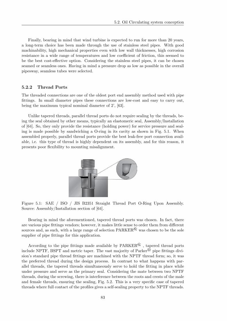
5.2. Oil Circulating system conception
Finally, bearing in mind that wind turbine is expected to run for more than 20 years,a long-term choice has been made through the use of stainless steel pipes. With goodmachinability, high mechanical properties even with low wall thicknesses, high corrosionresistance in a wide range of temperatures and low coefficient of friction, this seemed tobe the best cost-effective option. Considering the stainless steel pipes, it can be chosenseamed or seamless ones. Having in mind a pressure drop as low as possible in the overallpipesway, seamless tubes were selected.
5.2.2 Thread Ports
The threaded connections are one of the oldest port end assembly method used with pipefittings. In small diameter pipes these connections are low-cost and easy to carry out,being the maximum typical nominal diameter of 2’, [63].
Unlike tapered threads, parallel thread ports do not require sealing by the threads, be-ing the seal obtained by other means, typically an elastomeric seal, Assembly/Installationof [64]. So, they only provide the resistance (holding power) for service pressure and seal-ing is made possible by sandwiching a O-ring in its cavity as shown in Fig. 5.1. Whenassembled properly, parallel thread ports provide the best leak-free port connection avail-able, i.e. this type of thread is highly dependent on its assembly, and for this reason, itpresents poor flexibility to mounting misalignment.
Figure 5.1: SAE / ISO / JIS B2351 Straight Thread Port O-Ring Upon Assembly.Source: Assembly/Installation section of [64].
Bearing in mind the aforementioned, tapered thread ports was chosen. In fact, thereare various pipe fittings vendors; however, it makes little sense to order them from differentsources and, as such, with a large range of selection PARKER® was chosen to be the solesupplier of pipe fittings for this application.
According to the pipe fittings made available by PARKER® , tapered thread portsinclude NPTF, BSPT and metric taper. The vast majority of Parker® pipe fittings divi-sion’s standard pipe thread fittings are machined with the NPTF thread form; so, it wasthe preferred thread during the design process. In contrast to what happens with par-allel threads, the tapered threads simultaneously serve to hold the fitting in place whileunder pressure and serve as the primary seal. Considering the mate between two NPTFthreads, during the screwing, there is interference between the roots and crests of the maleand female threads, ensuring the sealing, Fig. 5.2. This is a very specific case of taperedthreads where full contact of the profiles gives a self-sealing property to the NPTF threads.
83

5. Lubrication system
However, variations in condition of mating threads; inadequate assembly procedures; and,disturbances in operating conditions, like the high vibration level of the WT gearbox,make self-sealing highly improbable. So, for a higher safety from leakage a sealant shallbe applied.
Figure 5.2: Tapered Thread Port. Source: Assembly/Installation section of [64].
5.2.3 Pipe End Assembly
In accordance to the section Assembly/Installation section of [64], the assembly of the pipeend consists of the following two steps:
1. Tube end preparation (cutting, deburring and cleaning)
2. Assembly and installation
Pipe end preparation is a very critical step to assure the integrity of a pipe assemblyand an error may result in leakage. The preparation or the cutting tools of the differentpipes will not be studied in this thesis; however, it is intended to leave a reference tothe particularity of the steel pipes cut, namely the stainless steel ones. During the cutprocess, it is recurrent to create a large burr on the inner diameter, which may be difficultto correctly remove from this materials, creating flow restriction. Therefore, it is advisableto choose carefully the pipe cutting process.
Fitting Body
O-ring
Parflange Sleeve
Nut
Braze sleeve
Straight connector
Figure 5.3: Sleeve attachment with flanged and brazed assemblies. Adapted from: Assem-bly/Installation section of [64].
This section is therefore intended to discuss one of the particular steps in the pipeend preparation process — the Sleeve Attachment. This can be accomplished by three
84

5.2. Oil Circulating system conception
methods: parflanging (or simply flanging), brazing and using a ferrule.
Pipe
Ferrule
Nut
Fitting
Ferrule
Figure 5.4: Sleeve attachment with ferrule assemblies. Adapted from: Assem-bly/Installation section of [64].
Parflange process is several times faster than the other two processes, especially thanthe braze one. It also does not require any special pre- or post-flange cleaning of the pipeand sleeve, like any brazing or welding process requires, or even requires any special pre-setting operation, like the ferrule process. Unlike brazing, the parflange process does notrequire any flux, braze alloy, post braze cleaner or rust inhibitor, being an environmentallysafe lubricant the only additive associated with it. Safer than brazing without the need ofan open flame or any form of heating, flanging process uses only a fraction of the energyneeded for welding or brazing. The parflange process accommodates the exclusive use ofpipe and sleeve, thus eliminating the need to an extra supporting sleeve typical in ferruleuse. It also eliminates the potential for leaks, originated from a too large gap, result of aimproper pipe cut (brazing) or a uneven bite (ferrule). For all these, and bearing in mindthat parflange process produces a burnished sealing surface typically much smoother thanthe 125 micro-inch requirement of SAE J1453|2, it was the sleeve attachment type selected.
Uneven biteToo large gap
Figure 5.5: Sleeve attachment with ferrule assemblies. Adapted from: Assem-bly/Installation section of [64].
Some attention is required in the application of the flanging process. Two of the mainprecautions, namely what is related to the dimensioning of the pipes, are: the extra cutt-off length and the minimum straight length to start of bend. The first refers to the extralength, in relation to the effective flow pipe length, that the pipe must have in order toallow the flanging process. A wrong extra cutt-off length chosen can cause: over-flanging,
2Specification for O-Ring Face Seal Connectors, by SAE Interneational.
85
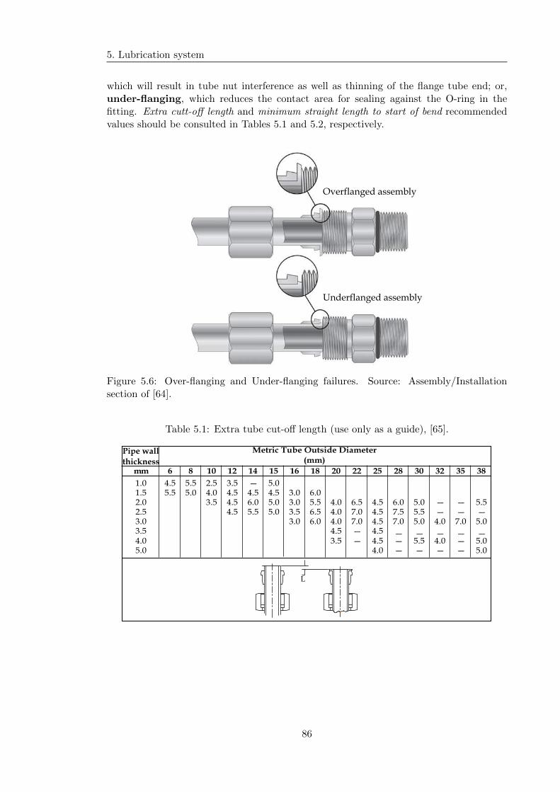
5. Lubrication system
which will result in tube nut interference as well as thinning of the flange tube end; or,under-flanging, which reduces the contact area for sealing against the O-ring in thefitting. Extra cutt-off length and minimum straight length to start of bend recommendedvalues should be consulted in Tables 5.1 and 5.2, respectively.
Overflanged assembly
Underflanged assembly
Figure 5.6: Over-flanging and Under-flanging failures. Source: Assembly/Installationsection of [64].
Table 5.1: Extra tube cut-off length (use only as a guide), [65].
Metric Tube Outside Diameter
(mm)
mm 6 8 10 12 14 15 16 18 20 22 25 28 30 32 35 38
1.0 4.5 5.5 2.5 3.5 — 5.0
1.5 5.5 5.0 4.0 4.5 4.5 4.5 3.0 6.0
2.0 3.5 4.5 6.0 5.0 3.0 5.5 4.0 6.5 4.5 6.0 5.0 — — 5.5
2.5 4.5 5.5 5.0 3.5 6.5 4.0 7.0 4.5 7.5 5.5 — — —
3.0 3.0 6.0 4.0 7.0 4.5 7.0 5.0 4.0 7.0 5.0
3.5 4.5 — 4.5 — — — — —
4.0 3.5 — 4.5 — 5.5 4.0 — 5.0
5.0 4.0 — — — — 5.0
Pipe wall
thickness
L
86
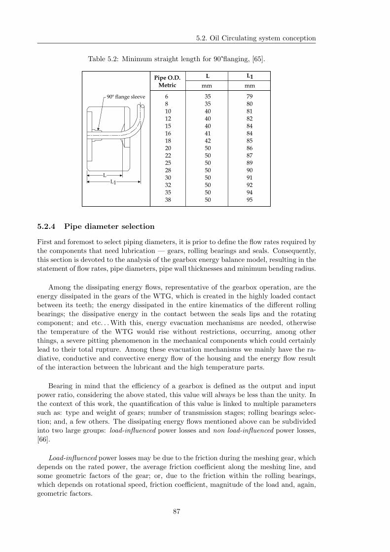
5.2. Oil Circulating system conception
Table 5.2: Minimum straight length for 90°flanging, [65].
L L1Pipe O.D.
Metric mm mm
353540404041425050505050505050
798081828484858687899091929495
6810121516182022252830323538
LL1
90º flange sleeve
5.2.4 Pipe diameter selection
First and foremost to select piping diameters, it is prior to define the flow rates required bythe components that need lubrication — gears, rolling bearings and seals. Consequently,this section is devoted to the analysis of the gearbox energy balance model, resulting in thestatement of flow rates, pipe diameters, pipe wall thicknesses and minimum bending radius.
Among the dissipating energy flows, representative of the gearbox operation, are theenergy dissipated in the gears of the WTG, which is created in the highly loaded contactbetween its teeth; the energy dissipated in the entire kinematics of the different rollingbearings; the dissipative energy in the contact between the seals lips and the rotatingcomponent; and etc. . . With this, energy evacuation mechanisms are needed, otherwisethe temperature of the WTG would rise without restrictions, occurring, among otherthings, a severe pitting phenomenon in the mechanical components which could certainlylead to their total rupture. Among these evacuation mechanisms we mainly have the ra-diative, conductive and convective energy flow of the housing and the energy flow resultof the interaction between the lubricant and the high temperature parts.
Bearing in mind that the efficiency of a gearbox is defined as the output and inputpower ratio, considering the above stated, this value will always be less than the unity. Inthe context of this work, the quantification of this value is linked to multiple parameterssuch as: type and weight of gears; number of transmission stages; rolling bearings selec-tion; and, a few others. The dissipating energy flows mentioned above can be subdividedinto two large groups: load-influenced power losses and non load-influenced power losses,[66].
Load-influenced power losses may be due to the friction during the meshing gear, whichdepends on the rated power, the average friction coefficient along the meshing line, andsome geometric factors of the gear; or, due to the friction within the rolling bearings,which depends on rotational speed, friction coefficient, magnitude of the load and, again,geometric factors.
87
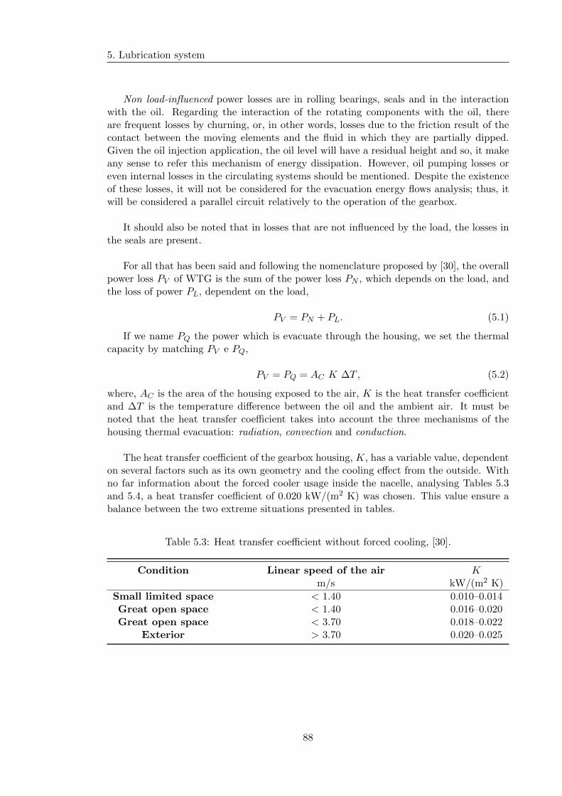
5. Lubrication system
Non load-influenced power losses are in rolling bearings, seals and in the interactionwith the oil. Regarding the interaction of the rotating components with the oil, thereare frequent losses by churning, or, in other words, losses due to the friction result of thecontact between the moving elements and the fluid in which they are partially dipped.Given the oil injection application, the oil level will have a residual height and so, it makeany sense to refer this mechanism of energy dissipation. However, oil pumping losses oreven internal losses in the circulating systems should be mentioned. Despite the existenceof these losses, it will not be considered for the evacuation energy flows analysis; thus, itwill be considered a parallel circuit relatively to the operation of the gearbox.
It should also be noted that in losses that are not influenced by the load, the losses inthe seals are present.
For all that has been said and following the nomenclature proposed by [30], the overallpower loss PV of WTG is the sum of the power loss PN , which depends on the load, andthe loss of power PL, dependent on the load,
PV = PN + PL. (5.1)
If we name PQ the power which is evacuate through the housing, we set the thermalcapacity by matching PV e PQ,
PV = PQ = AC K ∆T , (5.2)
where, AC is the area of the housing exposed to the air, K is the heat transfer coefficientand ∆T is the temperature difference between the oil and the ambient air. It must benoted that the heat transfer coefficient takes into account the three mechanisms of thehousing thermal evacuation: radiation, convection and conduction.
The heat transfer coefficient of the gearbox housing, K, has a variable value, dependenton several factors such as its own geometry and the cooling effect from the outside. Withno far information about the forced cooler usage inside the nacelle, analysing Tables 5.3and 5.4, a heat transfer coefficient of 0.020 kW/(m2 K) was chosen. This value ensure abalance between the two extreme situations presented in tables.
Table 5.3: Heat transfer coefficient without forced cooling, [30].
Condition Linear speed of the air Km/s kW/(m2 K)
Small limited space < 1.40 0.010–0.014Great open space < 1.40 0.016–0.020Great open space < 3.70 0.018–0.022
Exterior > 3.70 0.020–0.025
88

5.2. Oil Circulating system conception
Table 5.4: Heat transfer coefficient with forced cooling, [30].
Linear speed of the air Km/s kW/(m2 K)
2.5 0.0155 0.02410 0.04215 0.058
Given a heat transfer coefficient of 0.020 kW/(m2 K) and considering a 40 K betweenthe oil and the ambient air, with a estimating shape housing like presented in Figure 5.7,which results in a total surface area of 18.057 m2, it is obtained a power evacuation of about14.446 kW, Table 5.5. This amount of power evacuation corresponds to approximately 45% of the total sum of estimated losses in the contact between the teeth along meshing gearwith the losses in all rolling bearing,which was calculated with the KISSsoft® calculationtool for the nominal load.
Ø 2100
8001045
1300
1500
Figure 5.7: Estimated housing shape dimensions.
Table 5.5: Housing energy balance parameters and level of power evacuation.
Parameter Unit Value
total surface area, Ac m2 18.057Heat transfer coefficient, K kW/(m2 K) 0.020
Temperature variation K 40Housing heat evacuation per second kW 14.446
Looking at the percentage of power losses that would be possible to evacuate throughgearbox housing is backed up the option of injected lubrication. The oil bath, as sug-gested in Section 3.1.11.4 of the II Part, would certainly not be enough to dissipate allthe heat generated inside the WTG. In order to simplify the calculation, this dissipative
89

5. Lubrication system
effect of the housing will be neglected, being the piping dimensioning made based on theidea that all the heat generated must be evacuated through the interaction between thecomponents and the oil lubricant. In this way and since we have an estimate of housingheat evacuation of about 45 %, not considering it we shall have a safety coefficient of 1.45.
In addition, considering that the load spectrum proposed by the ISO 61400-4 standardincludes a bin with a load factor of 1.67, an additional safety coefficient of 1.5 was con-sidered. To summarize, relatively to the nominal load, the total oil required has a globalsafety coefficient of around 2.2, which is extremely reasonable since the pressure dropsalong the circuit are being neglected.
Regarding the volume of oil, in the case of the gears, the amount of oil considered(in l/min) was required by the calculations of the KISSsoft® software. About the rollingbearings, there are no far information about flow rates required for each of the differenttypes of rolling bearings and lubrication methods. Thus, following the recommended val-ues of SKF® for a recirculating oil system (tab. 5.6) and considering a upper factor of 1.2and 1.5 for bearings with asymmetric section with low and high power losses, respectively,the volume of oil obtained are shown in the Table 5.8. The 1.5 upper factor is due to theflow resistance that the rolling bearings may or may not offer. In fact the recommendedvalues of oil volume suggested by SKF® do not distinguish the type of bearings; however,for rolling bearings with an asymmetrical cross section —such tapered roller bearings orspherical roller thrust bearings— larger flow rates are permissible than for rolling bear-ings with a symmetrical cross section, because their flow resistance is lower due to theirpumping action. It was also considered an upper factor of 1.2 for the volume of oil of therolling bearings that, despite the symmetrical section presented, a higher level of powerlosses is verified. This is due to the fact that higher power losses imply hotter runs and,consequently, more energy to be dissipated.
Table 5.6: Oil flow rate guidelines by SKF®, [67].
Bore diameter Bore diameterdBR Q
mm l/min
over incl. low high
— 50 0.3 150 120 0.8 3.6120 400 1.8 6
In the Table 5.8, there are also shown the diameters of the pipes, which are responsiblefor the oil delivery to each gear pair as well as to each rolling bearing. The diametersI.D.v=2 were obtained through the equation,
I.D.v=2 =
(4
π
60x103 Voilvoil
) 12
, (5.3)
and assuming a linear speed of the oil lubricant voil of 2 m/s. In order to obtain a pipingsystem according to the nominal pipe diameters available in the market, the I.D.v=2
diameters were converted to the final diameters I.D.. They are according to the size guidesuggested by PARKER® in the table-5.7. In other words, assuming a wall thickness t close
90
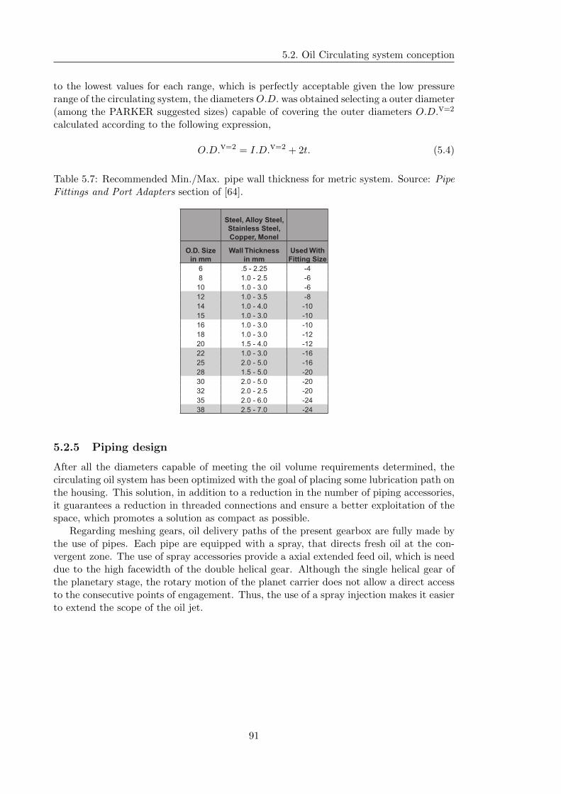
5.2. Oil Circulating system conception
to the lowest values for each range, which is perfectly acceptable given the low pressurerange of the circulating system, the diameters O.D. was obtained selecting a outer diameter(among the PARKER suggested sizes) capable of covering the outer diameters O.D.v=2
calculated according to the following expression,
O.D.v=2 = I.D.v=2 + 2t. (5.4)
Table 5.7: Recommended Min./Max. pipe wall thickness for metric system. Source: PipeFittings and Port Adapters section of [64].
Steel, Alloy Steel,
Stainless Steel,
Copper, Monel
O.D. Size
in mm
Wall Thickness
in mm
Used With
Fitting Size
6 .5 - 2.25 -4
8 1.0 - 2.5 -6
10 1.0 - 3.0 -6
12 1.0 - 3.5 -8
14 1.0 - 4.0 -10
15 1.0 - 3.0 -10
16 1.0 - 3.0 -10
18 1.0 - 3.0 -12
20 1.5 - 4.0 -12
22 1.0 - 3.0 -16
25 2.0 - 5.0 -16
28 1.5 - 5.0 -20
30 2.0 - 5.0 -20
32 2.0 - 2.5 -20
35 2.0 - 6.0 -24
38 2.5 - 7.0 -24
5.2.5 Piping design
After all the diameters capable of meeting the oil volume requirements determined, thecirculating oil system has been optimized with the goal of placing some lubrication path onthe housing. This solution, in addition to a reduction in the number of piping accessories,it guarantees a reduction in threaded connections and ensure a better exploitation of thespace, which promotes a solution as compact as possible.
Regarding meshing gears, oil delivery paths of the present gearbox are fully made bythe use of pipes. Each pipe are equipped with a spray, that directs fresh oil at the con-vergent zone. The use of spray accessories provide a axial extended feed oil, which is needdue to the high facewidth of the double helical gear. Although the single helical gear ofthe planetary stage, the rotary motion of the planet carrier does not allow a direct accessto the consecutive points of engagement. Thus, the use of a spray injection makes it easierto extend the scope of the oil jet.
91
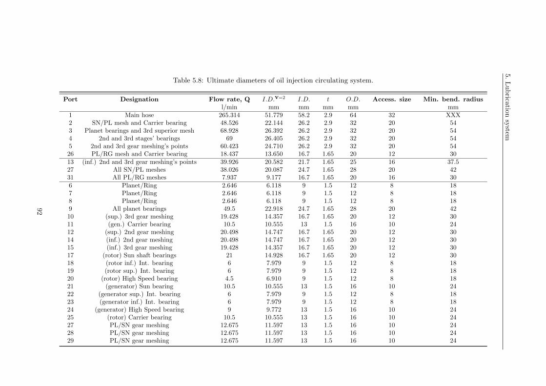
5.
Lu
brication
system
Table 5.8: Ultimate diameters of oil injection circulating system.
Port Designation Flow rate, Q I.D.v=2 I.D. t O.D. Access. size Min. bend. radiusl/min mm mm mm mm mm
1 Main hose 265.314 51.779 58.2 2.9 64 32 XXX2 SN/PL mesh and Carrier bearing 48.526 22.144 26.2 2.9 32 20 543 Planet bearings and 3rd superior mesh 68.928 26.392 26.2 2.9 32 20 544 2nd and 3rd stages’ bearings 69 26.405 26.2 2.9 32 20 545 2nd and 3rd gear meshing’s points 60.423 24.710 26.2 2.9 32 20 5426 PL/RG mesh and Carrier bearing 18.437 13.650 16.7 1.65 20 12 3013 (inf.) 2nd and 3rd gear meshing’s points 39.926 20.582 21.7 1.65 25 16 37.527 All SN/PL meshes 38.026 20.087 24.7 1.65 28 20 4231 All PL/RG meshes 7.937 9.177 16.7 1.65 20 16 306 Planet/Ring 2.646 6.118 9 1.5 12 8 187 Planet/Ring 2.646 6.118 9 1.5 12 8 188 Planet/Ring 2.646 6.118 9 1.5 12 8 189 All planet bearings 49.5 22.918 24.7 1.65 28 20 4210 (sup.) 3rd gear meshing 19.428 14.357 16.7 1.65 20 12 3011 (gen.) Carrier bearing 10.5 10.555 13 1.5 16 10 2412 (sup.) 2nd gear meshing 20.498 14.747 16.7 1.65 20 12 3014 (inf.) 2nd gear meshing 20.498 14.747 16.7 1.65 20 12 3015 (inf.) 3rd gear meshing 19.428 14.357 16.7 1.65 20 12 3017 (rotor) Sun shaft bearings 21 14.928 16.7 1.65 20 12 3018 (rotor inf.) Int. bearing 6 7.979 9 1.5 12 8 1819 (rotor sup.) Int. bearing 6 7.979 9 1.5 12 8 1820 (rotor) High Speed bearing 4.5 6.910 9 1.5 12 8 1821 (generator) Sun bearing 10.5 10.555 13 1.5 16 10 2422 (generator sup.) Int. bearing 6 7.979 9 1.5 12 8 1823 (generator inf.) Int. bearing 6 7.979 9 1.5 12 8 1824 (generator) High Speed bearing 9 9.772 13 1.5 16 10 2425 (rotor) Carrier bearing 10.5 10.555 13 1.5 16 10 2427 PL/SN gear meshing 12.675 11.597 13 1.5 16 10 2428 PL/SN gear meshing 12.675 11.597 13 1.5 16 10 2429 PL/SN gear meshing 12.675 11.597 13 1.5 16 10 24
92

5.2.O
ilC
irculatin
gsy
stemcon
ception
planet carrierbearing
planet/ringmeshing
2nd gear meshing (superior)
2nd gear meshing (inferior)
3rd gear meshing (superior)
sun/planetmeshing
planet carrierbearing
3 x 2 planet gear bearings
inf. intermediate bearing (generator side)
sup.. intermediate bearing (generator side)
high speed bearing (generator side)
sun bearing (rotor side)
inf. int. bearing (rotor side)
sup. int. bearing (rotor side)
high speed bearing (rotor side)
sun bearing (generator side)
3rd gear meshing (inferior)
1
3
2
526
11
27
28
30
29
10
20
24
19 23
18 22
17 21
13
14
15
12
25
316
7
8
9
4
Figure 5.8: Circulating oil desgin.
93

5. Lubrication system
94

Part IV
95

Chapter 6
Conclusion and future work
6.1 Conclusions
The main objective of this dissertation was the design of a gearbox for a 2 MW windturbine capable of verifying the speed increase of its rotor at a speed compatible with thegeneration of energy by the generator.
It was started by a market study that allowed to situate us among the current practice,moving later on the kinematic analysis, calculation of resistance and life time of the gearsand rolling bearings. The driver lines have always been to ensure the highest efficiencyand the smallest size as much as possible.
After the remaining mechanical components were chosen, the gearbox thermal balancewas analysed, allowing the dimensioning and design of a lubrication system. This includespiping, housing integrated lubrication paths and threaded fittings.
Finally, the assembly drawing was made, being susceptible to improvements after thepublic defense of this dissertation. It was expected to present the drawing of the mainparts after all argued.
In the following topics, an overview of the various chapter and conclusions reached willbe presented.
Chapter 3
This chapter was essentially devoted to the study of the chain of transmission. The crite-rion of the sum of profile shift coefficients always positive was followed for external gearingand preferred for internal gears. The preference for lower modules values was also pre-ferred, minimizing the sliding effects and allowing a more efficient solutions.
In this chapter, a gearbox performing a three transmission stages layout was obtained.It has a first planetary stage and a double branch solution for the 2nd and 3rd transmissionstages. The main advantage of the double branch was the possibility of deactivating oneof the power paths for maintenance, keeping the remaining path, even below the full ratedpower, in operation.
97
6. Conclusion and future work
Chapter 4
This chapter was mainly focused on the optimization of the solution obtained in the pre-vious chapter, allowing small important adjustments.
With the application of the load spectrum there was essentially an impact on the lifetime of the rolling bearings, in the sense of increasing the longevity of their operation.With the application of modifications in the tooth profile a significant improvement intooth resistance was observed, namely in the bending resistance in the root of the tooth.This was, in general, the limiting strength factor.
In this chapter, the application of mechanisms to relieve the stress concentrations phe-nomenon was also briefly discussed.
In addition, the particular assembly of the second part of this gearbox was treated.It should be noted that having the second and third transmission stages connected tothe same input and output shafts, respectively, it can be said the gearbox mounting is inclosed mesh, not allowing relative angular displacement between the power transmissionelements of the same intermediate shaft. Here, it is proved that it is possible to determinethe angular mismatch between the referred elements, being a well defined position provideran adequate assembly.
All the selection of rolling bearings, as well as, the application of spline joints wasdiscussed in this chapter, aiming the pursuit of greater efficiency.
Chapter 5
In this part of the thesis was made a brief theorical introduction to what is lubrication,as well as, its applicability to the most important mechanical elements. It could be con-cluded that this is a EHD type of lubrication with a high level of heat generated. As aconsequence an oil injection lubrication system was chosen instead of insufficient oil bathlubrication.
6.2 Future Work
Given the scale of the task proposed, a continuation of this work is needed to reach theproposed objective. The following list shows the main additions and changes needed tomeet the objective:
� Although the current solution is satisfactory, different combinations of parametersmust be developed and tested in the dimensioning of the transmission chain gears,which can improve their efficiency,
� A study with a broader spectrum could be carried out in order to avoid a somewhatoversized solution. Note that this was not possible given the high computationalcost;
� Expand and verify the practical applicability of the calculated angular mismatch ofthe upper and lower intermediate gears. Not only the manufacturing implications of
98
6.2. Future Work
this solution can be studied, as well as, the exploration of a mechanism that allowsfree angular displacement between the second stage pinion and the third stage gear,during assembly;
� The maximum deflection in gear zones was a bit higher than the typical hundredthof a module. This decision was essentially due to the importance of ensuring asomewhat floating assembly along the entire chain of transmission, since in all thetransmission stages there is a split power, ideally, balanced. Note that the criteriaof a deflection-total length ratio range of [0.001;0.003] was fully accomplished for allshafts. This leads to the suggestion of a more detailed analysis of these fluctuationintervals in which must be taken into account, for example, manufacturing deviationsand deformation of the flanks teeth during the gear meshing;
� The amount of oil for lubricating the rolling bearings was made according to guidancevalues of SKF producer and it were considered upper factors for the rolling bearingswith more critical behaviors. It is suggested to verify the sufficiency of these factorsfaces up the asymmetry characteristics of some types of rolling bearings;
� It is known that the storage of the oil in the bottom of a general gearbox can providethe increase of its temperature, as well as, the appearance of drag effects between themoving parts and the fluid; however, due to the typical low rotational speed of theplanet carrier, which characterize the first transmission stage of the wind turbines,these effects were neglected and it was considered, even a small ones, a determinedlevel of oil. It is therefore suggested that the appropriate residual oil level to bechecked in the planetary gear;
� It would be interesting to carry out a study of the geometry and wall thickness ofthe housing, in sense of the best energy dissipation as well as its mass reduction;
� Finally, and with extreme relevance, it is suggest the analysis, parameterized studyand design of a coupling system. It is known that dynamic and/or vibratory behaviorin wind turbines is extremely critical contributing to high noise levels. Given theneed for meticulous analysis for small improvements, this was not analyzed in thisdissertation. However, it would be interesting as future work the conception ofpositioning mechanisms capable of supporting and control this dynamic behaviour.
99

6. Conclusion and future work
100

References
1 WindEurope. Wind in power: 2016 european statistics. Statistical review, February2017.
2 Global Wind Energy Council GWEC. Global wind report: annual market update 2016.URL http://gwec.net/global-figures/graphs/. [Accessed May 18, 2017].
3 Bin Wu, Yongqiang Lang, Navid Zargari, and Samir Kouro. Power Conversion andControl of Wind Energy Systems. Wiley, 2011.
4 power technology.com. The world’s 10 biggest wind turbines. URL http://www.power-
technology.com/features/featurethe-worlds-biggest-wind-turbines-
4154395/. [Accessed February 25, 2017].
5 Eize de Vries. Close up - the e126, still the world’s biggest turbine.URL http://www.windpowermonthly.com/article/1138562/close--e126-worlds-
biggest-turbine. [Accessed February 25, 2017].
6 Joshua S Hill. Vestas’ 8 megawatt “world’s most powerful wind turbine” getting a work-out in uk & belgian waters. URL https://cleantechnica.com/2016/12/16/vestas-
8-mw-worlds-powerful-wind-turbine-getting-workout-uk-belgium-waters/. [Ac-cessed February 25, 2017].
7 The WindPower. B37/450 (bonus). Data sheet, December 2016.
8 ENERCON. Technology & service. Data sheet, June 2015.
9 REpower systems AG. 5m. Data sheet, October 2004.
10 Senvion. 6.2m152. Data sheet, 2016.
11 Vestas®. Vestas annual report 2015. Technical report, 2015.
12 LAZARD. Lazard’s levelized cost of energy analysis. Statistical review, December 2016.
13 International Renewable Energy Agency. Renewable energy technologies: Cost analysisseries. Statistical review, June 2012.
14 S. Sumathi, L. Ashok Kumar, and P. Surekha. Solar PV and Wind Energy ConversionSystems. Springer, 2015.
15 NREL. Application requirements for wind turbine gearboxes. Technical report, Septem-ber 1994.
16 WindpowerEngineering. Gears & gearboxes 101, 2012. URLhttp://www.windpowerengineering.com/design/mechanical/gearboxes/gears-
gearboxes-101/. [Accessed June 4, 2017].
101
REFERENCES
17 Joshua Earnest. Wind Power Technology. PHI Learning Pvt. Ltd., 2014.
18 H. Dinner. Gearing analysis for wind turbine, seen as a process. KISSsoft AG. [Datenot specified ].
19 MAAG Gear Company Ltd. Wind Power Technology. Schellenberg Druck AG, 1990.
20 Jim Marsch and Amy Flanagan. Epicyclic gearing: A handbook. URLhttp://www.gearsolutions.com/article/detail/5837/epicyclic-gearing-a-
handbook. [Accessed June 7, 2017].
21 Statista Inc. Global market share of the world’s leading wind turbine manufacturers in2016. URL https://www.statista.com/statistics/272813/market-share-of-the-
leading-wind-turbine-manufacturers-worldwide/. [Accessed March 3, 2017].
22 Siemens AG. Wind turbine swt-2.3-101. Data sheet, 2015.
23 S.A. Gamesa Corporacion Tecnologica. Platform catalogue. Catalog, 2016.
24 TechNavio. Global wind turbine gearbox market 2016-2020. Statistical review, Novem-ber 2016.
25 ZF Friedrichshafen AG. Zf technology in wind turbines. URLhttps://cleantechnica.com/2016/12/16/vestas-8-mw-worlds-powerful-wind-
turbine-getting-workout-uk-belgium-waters/. [Accessed April 24, 2017].
26 Stephen P. Radzevich. Dudley’s Handbook of Practical Gear Design and Manufacture.CRC Press, 2nd edition, 2012.
27 Paulo M. S. Tavares de Castro. Engrenagens. Faculdade de Engenharia da Universidadedo Porto, Porto, 2015.
28 M. G. Henriot. Etude des trains epicycloıdaux. Societe d’Etudes de l’Industrie del’Engrenage. [Date not specified ].
29 Joao Pedro Barbosa de Sousa. Desgin and dimensioning of a test rig for a efficiencymeasurements of wind turbine gearbox up to 2.5 MW. Master thesis, Faculdade deEngenharia da Universidade do Porto, Porto, October 2016.
30 Georges Henriot. Engrenages. DUNOD, Paris, 7th edition, 1999.
31 Armando Campos Vilaca. Engrenagens. Instituto Superior de Engenharia do Porto,Porto, 2010.
32 Carlos M. C. G. Fernandes. Power loss in rolling bearing and gears lubricated with windturbines gear oils. Master thesis, Faculdade de Engenharia da Universidade do Porto,Porto, 2015.
33 Ramada Acos. Improving together. Catalog, September 2009.
34 International Electrotechnical Commission IEC. IEC 61400-4. Wind turbines - Designrequirements for wind turbine gearboxes, draft version voted in 2010-2011.
35 Sergio M. O. Tavares and Paulo M. S. Tavares de Castro. O calculo da capacidade decarga de engrenagens cilındricas. Faculdade de Engenharia da Universidade do Porto,Porto, 201.
102
REFERENCES
36 Wolfgang Bock and Henrik Heinemann. Lubricants for wind turbines: Gear oils-demandsand characteristics. Lubetech Magazine, (112):18–23, December 2012.
37 Don M. Pirro, A. A. Wessol, and Ekkehard Daschner. Lubrication fundamentals. MarcelDekker, United States of America, 2nd edition, 2001.
38 Castrol. Castrol optigear synthetic x 320. Data sheet, March 2010.
39 American Gear Manufacturers Association AGMA. AGMA 925-A03: Effect of Lubri-cation on Gear Surface Distress, 2003.
40 Kluber Lubrication M’unchen. Useful information on scuffing load tests. FreudenbergGroup, 2007.
41 Michael Hochmann and Hermann Siebert. Gear lubrication — stopping micropitting byusing the right lubricant. Kluber Lubrication M’unchen, 2012.
42 Georges Henriot. Traite theorique et pratique des engrenages, volume 2. DUNOD, Paris,5th edition, 1983.
43 Georges Henriot. Traite theorique et pratique des engrenages, volume 1. DUNOD, Paris,6th edition, 1983.
44 Jose-Antonio Vilan-Vilan, Abraham Segade-Robleda, Marcos Lopez-Lago, and EnriqueCasarejos-Ruiz. Split Torque Gearboxes: Requirements, Performance and Applications.University of Vigo, Spain, post-2005 period.
45 Robert L. Norton. Machine design : an integrated approach. Upper Saddle River, 1998.
46 Samuel Koechlin. Fkm guideline: strengths, limitations and experimental validation.ScienceDirect. Elsevier, 2015.
47 FKM. Fkm-Guideline: Analytical Strength Assessment, 2003.
48 M. Movnin and D. Goltziker. Machine design. 1975.
49 SKF Group®. Rolling bearings. Catalog, August 2016.
50 Schaeffler Technologies GmbH & Co. KG®. Technical pocket guide. Technical report,March 2014.
51 TIMKEN®. Tapered roller bearing. Catalog, 2016.
52 International Organization for Standardization ISO. ISO/TS 16281:2008. Rolling Bear-ings - Methods for Calculating the Modified Reference Rating Life for Universally LoadedBearings, 2008.
53 Harold A. Rothbart. Mechanical Design and Systems Handbook. United States of Amer-ica, 1964.
54 International Organization for Standardization ISO. ISO 4156-1:2005. Straight cylin-drical involute splines—Metric module, side fit—Part 1: Generalities, 2005.
55 Joseph Edward Shigley. Mechanical Design and Systems Handbook. 3rd edition, 1963.
56 International Organization for Standardization ISO. ISO 4156-2:2005. Straight cylin-drical involute splines—Metric module, side fit—Part 2: Dimensions, 2005.
103
REFERENCES
57 VARGUS Ltd. Gear milling for gear, spline & rach manufacturing. Catalog, June 2016.
58 Simrit®. Simmerrings and rotary seals. Catalog, 2007.
59 Bernd Koch. New ideas in wind turbine main bearing and gear seals. URLhttp://www.windpowerengineering.com/design/new-ideas-wind-turbine-main-
bearing-gear-seals/. [Accessed June 28, 2017].
60 Simrit®. Industrial shaft seals. Catalog, 2007.
61 SKF Group®. Industrial shaft seals. Catalog, June 2013.
62 Seeger-Orbis®. Catalogue seeger rings. Catalog, 2007.
63 Pedro Carlos Telles. Tubulacoes industriais: materiais, projeto, montagem. Rio deJaneiro, 9th edition, 1997.
64 Parker Hannifin Corporation. Industrial tube fittings, adapters and equipment: Catalog4300. Catalog, 2017.
65 Parker Hannifin Corporation. Parker Seal-Lok® Fittings: Parflange and AssemblyGuide. United States of America, 1999.
66 Jorge H. O. Seabra, Armando Vilaca Campos, and Alexandre Sottomayor. Lubrificacaoelastohidrodinamina. Faculdade de Engenharia da Universidade do Porto, Porto, 2002.
67 SKF Group®. Oil lubrication methods: Circulating oil. URLhttp://www.skf.com/uk/products/bearings-units-housings/super-precision-
bearings/principles/lubrication/oil-lubrication/oil-lubrication-
methods/index.html. [Accessed July 30, 2017].
68 International Organization for Standardization ISO. ISO 281:2007. Rolling Bearings -Dynamic Load Ratings and Rating Life, 2007.
104
Appendix A
KISSsoft Reports
A.1 KISSsoft Reports - Gearing calculation
105

A. KISSsoft Reports
106

A.1. KISSsoft Reports - Gearing calculation
A.1.1 KISSsoft Report - Planetary stage
107

A. KISSsoft Reports
108
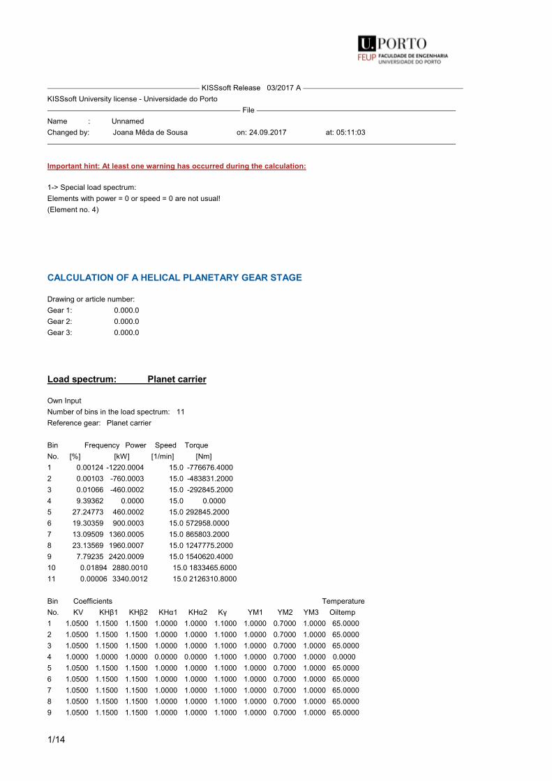
1/14
KISSsoft Release 03/2017 A KISSsoft University license - Universidade do Porto File Name : UnnamedChanged by: Joana Mêda de Sousa on: 24.09.2017 at: 05:11:03
Important hint: At least one warning has occurred during the calculation:
1-> Special load spectrum:Elements with power = 0 or speed = 0 are not usual!(Element no. 4)
CALCULATION OF A HELICAL PLANETARY GEAR STAGE
Drawing or article number:Gear 1: 0.000.0Gear 2: 0.000.0Gear 3: 0.000.0
Load spectrum: Planet carrier
Own InputNumber of bins in the load spectrum: 11Reference gear: Planet carrier
Bin Frequency Power Speed TorqueNo. [%] [kW] [1/min] [Nm]1 0.00124 -1220.0004 15.0 -776676.40002 0.00103 -760.0003 15.0 -483831.20003 0.01066 -460.0002 15.0 -292845.20004 9.39362 0.0000 15.0 0.00005 27.24773 460.0002 15.0 292845.20006 19.30359 900.0003 15.0 572958.00007 13.09509 1360.0005 15.0 865803.20008 23.13569 1960.0007 15.0 1247775.20009 7.79235 2420.0009 15.0 1540620.400010 0.01894 2880.0010 15.0 1833465.600011 0.00006 3340.0012 15.0 2126310.8000
Bin Coefficients TemperatureNo. KV ΚΗβ1 ΚΗβ2 ΚΗα1 ΚΗα2 Κγ YM1 YM2 YM3 Oiltemp1 1.0500 1.1500 1.1500 1.0000 1.0000 1.1000 1.0000 0.7000 1.0000 65.00002 1.0500 1.1500 1.1500 1.0000 1.0000 1.1000 1.0000 0.7000 1.0000 65.00003 1.0500 1.1500 1.1500 1.0000 1.0000 1.1000 1.0000 0.7000 1.0000 65.00004 1.0000 1.0000 1.0000 0.0000 0.0000 1.1000 1.0000 0.7000 1.0000 0.00005 1.0500 1.1500 1.1500 1.0000 1.0000 1.1000 1.0000 0.7000 1.0000 65.00006 1.0500 1.1500 1.1500 1.0000 1.0000 1.1000 1.0000 0.7000 1.0000 65.00007 1.0500 1.1500 1.1500 1.0000 1.0000 1.1000 1.0000 0.7000 1.0000 65.00008 1.0500 1.1500 1.1500 1.0000 1.0000 1.1000 1.0000 0.7000 1.0000 65.00009 1.0500 1.1500 1.1500 1.0000 1.0000 1.1000 1.0000 0.7000 1.0000 65.0000

2/14
10 1.0500 1.1500 1.1500 1.0000 1.0000 1.1000 1.0000 0.7000 1.0000 65.000011 1.0500 1.1500 1.1500 1.0000 1.0000 1.1000 1.0000 0.7000 1.0000 65.0000
Notice:- Tooth flank with load spectrum: Check both cases and document the unfavorable case- Tooth root with load spectrum: Check both cases and document the more realistic case (DIN3990-6, Method C) Is only applied on load spectrum bins, where the alternating bending factor (mean stress influence factor) YM=1.0.
S-N curve (Woehler line) in the endurance domain according: according to standard
Notice:Calculation with methods ISO6336 and AGMA 2001 results in a reduction of resistance in the domain of fatigue resistance (from circa 10^7to 10^10 cycles).The lifetime calculation takes this into account (also with the S-N curve (Woehler Curve) of the Miner type).
Results
Safeties, calculated with load spectrum:Root safety 2.295 1.566 / 1.867 2.234Flank safety 1.380 1.462 / 3.082 2.489
Safeties against scuffing/micropitting/EHT/TFF are indicated for the most critical element of the load spectrum:Scuffing safety (integral temperature) 3.251 5.022Scuffing safety (flash temperature) 2.845 21.955Safety against micropitting (B) 1.094 1.838
Safeties, calculated with nominal torque:Safety against micropitting (B) 1.335 2.024
Analysis of critical elements in load spectrum: See section 10
ONLY AS INFORMATION: CALCULATION WITH REFERENCE POWER
Calculation method ISO 6336:2006 Method B
------- Sun ----------- Planets ----------- Internal gear ---Number of planets [p] (1) 3 (1)
Power (kW) [P] 2000.001Speed (1/min) [n] 77.9 0.0Speed difference for planet bearing calculation (1/min) [n2] 39.9Speed planet carrier (1/min) [nSteg] 15.0
Torque (Nm) [T] 245216.6 0.0 1028023.4Torque Pl.-Carrier (Nm) [TSteg] 1273240.000
Application factor [KA] 1.00Distribution factor [Kgam] 1.10Required service life (h) [H] 175200.00Gear driving (+) / driven (-) - +/- +Working flank gear 1: Left flankSense of rotation gear 1 clockwise

3/14
1. TOOTH GEOMETRY AND MATERIAL
(geometry calculation according to ISO 21771:2007, DIN ISO 21771) ------- GEAR 1 ------------ GEAR 2 ------------ GEAR 3 ---Center distance (mm) [a] 566.000Centre distance tolerance ISO 286:2010 Measure js7
Normal module (mm) [mn] 16.0000Pressure angle at normal section (°) [alfn] 20.0000Helix angle at reference circle (°) [beta] 15.0000Number of teeth [z] 26 41 -109Facewidth (mm) [b] 265.00 256.00 265.00Hand of gear left right right
Planetary axles can be placed in regular pitch.: 120°
Accuracy grade [Q-ISO1328:1995] 6 6 7Inner diameter (mm) [di] 0.00 0.00External diameter (mm) [di] 1975.54Inner diameter of gear rim (mm) [dbi] 0.00 0.00Outer diameter of gear rim (mm) [dbi] 0.00
MaterialGear 1: 18CrNiMo7-6, Case-carburized steel, case-hardened ISO 6336-5 Figure 9/10 (MQ), Core hardness >=30HRCGear 2: 18CrNiMo7-6, Case-carburized steel, case-hardened ISO 6336-5 Figure 9/10 (MQ), Core hardness >=30HRCGear 3: 42 CrMo 4 (2), Through hardened steel, flame/ind. hardened ISO 6336-5 Figure 11/12 (MQ) Flank & root hardened ------- GEAR 1 ------------ GEAR 2 ------------ GEAR 3 ---Surface hardness HRC 61 HRC 61 HRC 56Material quality according to ISO 6336:2006 Normal (Life factors ZNT and YNT >=0.85)Fatigue strength. tooth root stress (N/mm²) [σFlim] 500.00 500.00 370.00Fatigue strength for Hertzian pressure (N/mm²) [σHlim] 1500.00 1500.00 1220.00Tensile strength (N/mm²) [σB] 1200.00 1200.00 1100.00Yield point (N/mm²) [σS] 850.00 850.00 900.00Young's modulus (N/mm²) [E] 206000 206000 206000Poisson's ratio [ν] 0.300 0.300 0.300Roughness average value DS, flank (µm) [RAH] 0.50 0.50 0.60Roughness average value DS, root (µm) [RAF] 3.00 3.00 3.00Mean roughness height, Rz, flank (µm) [RZH] 3.00 3.00 4.80Mean roughness height, Rz, root (µm) [RZF] 20.00 20.00 20.00
Gear reference profile 1 :Reference profile 1.25 / 0.38 / 1.0 ISO 53:1998 Profil ADedendum coefficient [hfP*] 1.250Root radius factor [rhofP*] 0.380 (rhofPmax*= 0.472)Addendum coefficient [haP*] 1.000Tip radius factor [rhoaP*] 0.000Protuberance height coefficient [hprP*] 0.000Protuberance angle [alfprP] 0.000Tip form height coefficient [hFaP*] 0.000Ramp angle [alfKP] 0.000 not topping
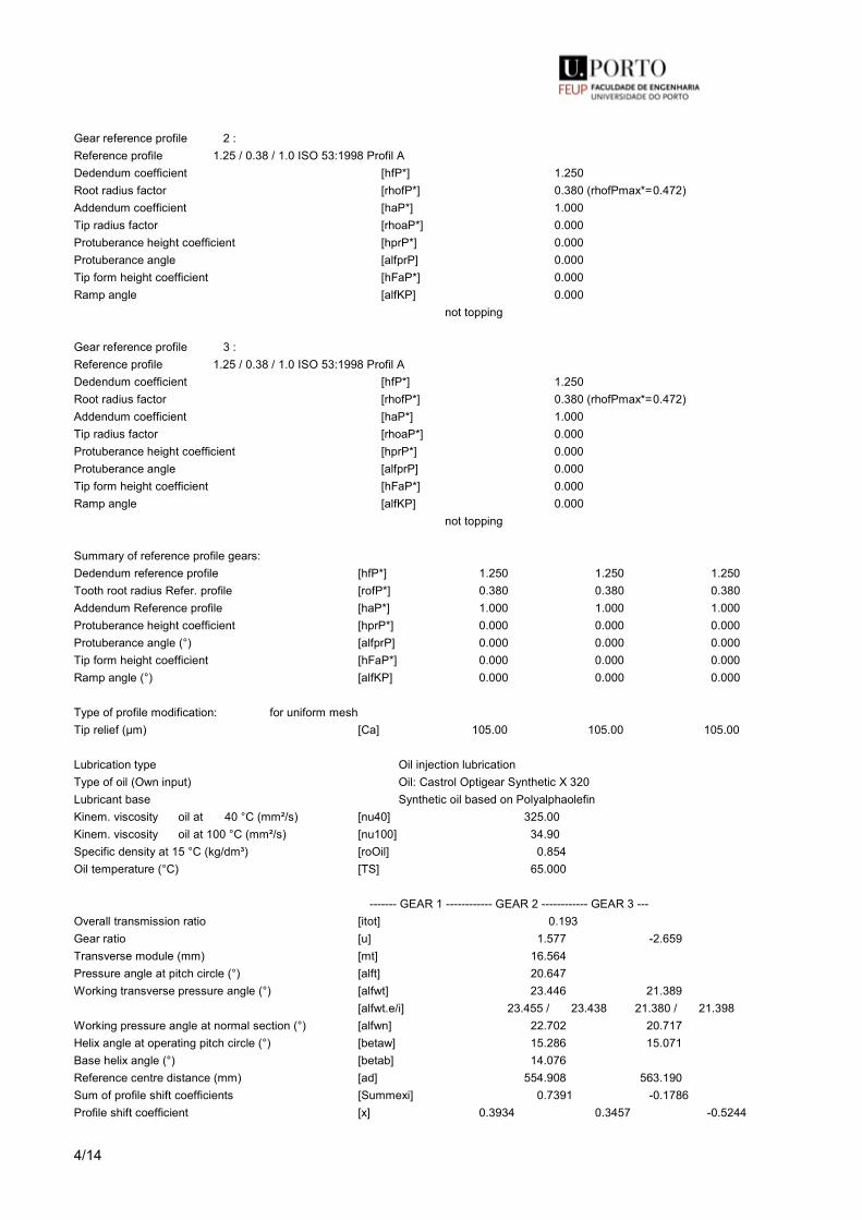
4/14
Gear reference profile 2 :Reference profile 1.25 / 0.38 / 1.0 ISO 53:1998 Profil ADedendum coefficient [hfP*] 1.250Root radius factor [rhofP*] 0.380 (rhofPmax*= 0.472)Addendum coefficient [haP*] 1.000Tip radius factor [rhoaP*] 0.000Protuberance height coefficient [hprP*] 0.000Protuberance angle [alfprP] 0.000Tip form height coefficient [hFaP*] 0.000Ramp angle [alfKP] 0.000 not topping
Gear reference profile 3 :Reference profile 1.25 / 0.38 / 1.0 ISO 53:1998 Profil ADedendum coefficient [hfP*] 1.250Root radius factor [rhofP*] 0.380 (rhofPmax*= 0.472)Addendum coefficient [haP*] 1.000Tip radius factor [rhoaP*] 0.000Protuberance height coefficient [hprP*] 0.000Protuberance angle [alfprP] 0.000Tip form height coefficient [hFaP*] 0.000Ramp angle [alfKP] 0.000 not topping
Summary of reference profile gears:Dedendum reference profile [hfP*] 1.250 1.250 1.250Tooth root radius Refer. profile [rofP*] 0.380 0.380 0.380Addendum Reference profile [haP*] 1.000 1.000 1.000Protuberance height coefficient [hprP*] 0.000 0.000 0.000Protuberance angle (°) [alfprP] 0.000 0.000 0.000Tip form height coefficient [hFaP*] 0.000 0.000 0.000Ramp angle (°) [alfKP] 0.000 0.000 0.000
Type of profile modification: for uniform meshTip relief (µm) [Ca] 105.00 105.00 105.00
Lubrication type Oil injection lubricationType of oil (Own input) Oil: Castrol Optigear Synthetic X 320Lubricant base Synthetic oil based on PolyalphaolefinKinem. viscosity oil at 40 °C (mm²/s) [nu40] 325.00Kinem. viscosity oil at 100 °C (mm²/s) [nu100] 34.90Specific density at 15 °C (kg/dm³) [roOil] 0.854Oil temperature (°C) [TS] 65.000
------- GEAR 1 ------------ GEAR 2 ------------ GEAR 3 ---Overall transmission ratio [itot] 0.193Gear ratio [u] 1.577 -2.659Transverse module (mm) [mt] 16.564Pressure angle at pitch circle (°) [alft] 20.647Working transverse pressure angle (°) [alfwt] 23.446 21.389 [alfwt.e/i] 23.455 / 23.438 21.380 / 21.398Working pressure angle at normal section (°) [alfwn] 22.702 20.717Helix angle at operating pitch circle (°) [betaw] 15.286 15.071Base helix angle (°) [betab] 14.076Reference centre distance (mm) [ad] 554.908 563.190Sum of profile shift coefficients [Summexi] 0.7391 -0.1786Profile shift coefficient [x] 0.3934 0.3457 -0.5244
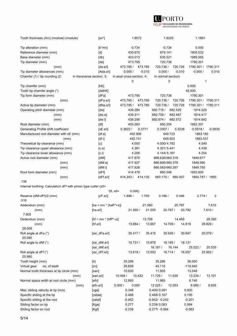
5/14
Tooth thickness (Arc) (module) (module) [sn*] 1.8572 1.8225 1.1891
Tip alteration (mm) [k*mn] -0.734 -0.734 0.000Reference diameter (mm) [d] 430.675 679.141 1805.522Base diameter (mm) [db] 403.013 635.521 1689.555Tip diameter (mm) [da] 473.795 720.736 1790.301 (mm) [da.e/i] 473.795 / 473.785 720.736 / 720.726 1790.301 / 1790.311Tip diameter allowances (mm) [Ada.e/i] 0.000 / -0.010 0.000 / -0.010 -0.000 / 0.010Chamfer (1) / tip rounding (2: in transverse section, 3: in axial cross-section, 4: In normal section) 0 0 1Tip chamfer (mm) [hK] 0.000Tooth tip chamfer angle (°) [delhK] 45.000Tip form diameter (mm) [dFa] 473.795 720.736 1790.301 (mm) [dFa.e/i] 473.795 / 473.785 720.736 / 720.726 1790.301 / 1790.311Active tip diameter (mm) [dNa.e/i] 473.795 / 473.785 720.736 / 720.726 1790.301 / 1790.311Operating pitch diameter (mm) [dw] 439.284 692.716 / 682.529 1814.529 (mm) [dw.e] 439.311 692.759 / 682.487 1814.417 (mm) [dw.i] 439.256 692.674 / 682.572 1814.642Root diameter (mm) [df] 403.263 650.204 1862.301Generating Profile shift coefficient [xE.e/i] 0.3822 / 0.3771 0.3307 / 0.3238 -0.5518 / -0.5630Manufactured root diameter with xE (mm) [df.e] 402.906 649.723 1863.180 (mm) [df.i] 402.741 649.503 1863.537Theoretical tip clearance (mm) [c] 4.000 4.000/ 4.783 4.049Tip clearance upper allowance (mm) [c.e] 4.391 4.301/ 5.441 4.439Tip clearance lower allowance (mm) [c.i] 4.206 4.144/ 5.187 4.254Active root diameter (mm) [dNf] 417.875 666.636/ 660.319 1849.677 (mm) [dNf.e] 417.927 666.695/ 660.379 1849.590 (mm) [dNf.i] 417.828 666.583/ 660.267 1849.755Root form diameter (mm) [dFf] 414.478 660.546 1853.920 (mm) [dFf.e/i] 414.243 / 414.135 660.175 / 660.007 1854.787 / 1855.138Internal toothing: Calculation dFf with pinion type cutter (z0= 35, x0= 0.000)Reserve (dNf-dFf)/2 (mm) [cF.e/i] 1.896 / 1.793 0.186 / 0.046 2.774 / 2.516Addendum (mm) [ha = mn * (haP*+x)] 21.560 20.797 7.610 (mm) [ha.e/i] 21.560 / 21.555 20.797 / 20.792 7.610 / 7.605Dedendum (mm) [hf = mn * (hfP*-x)] 13.706 14.469 28.390 (mm) [hf.e/i] 13.884 / 13.967 14.709 / 14.819 28.829 / 29.008Roll angle at dFa (°) [xsi_dFa.e/i] 35.417 / 35.415 30.649 / 30.647 20.079 / 20.080Roll angle to dNf (°) [xsi_dNf.e/i] 15.731 / 15.678 18.165 / 18.131 [xsi_dNf.e/i] 16.181 / 16.144 25.522 / 25.535Roll angle at dFf (°) [xsi_dFf.e/i] 13.619 / 13.553 16.114 / 16.057 25.952 / 25.980Tooth height (mm) [h] 35.266 35.266 36.000Virtual gear no. of teeth [zn] 28.609 45.115 -119.940Normal tooth thickness at tip circle (mm) [san] 10.630 11.905 13.548 (mm) [san.e/i] 10.494 / 10.422 11.725 / 11.635 13.234 / 13.101Normal space width at root circle (mm) [efn] 12.893 11.965 8.740 (mm) [efn.e/i] 0.000 / 0.000 12.025 / 12.053 8.680 / 8.655Max. sliding velocity at tip (m/s) [vga] 0.346 0.400/ 0.091 0.000Specific sliding at the tip [zetaa] 0.488 0.488/ 0.167 0.195Specific sliding at the root [zetaf] -0.952 -0.952/ -0.242 -0.201Sliding factor on tip [Kga] 0.277 0.239/ 0.083 0.064Sliding factor on root [Kgf] -0.239 -0.277/ -0.064 -0.083
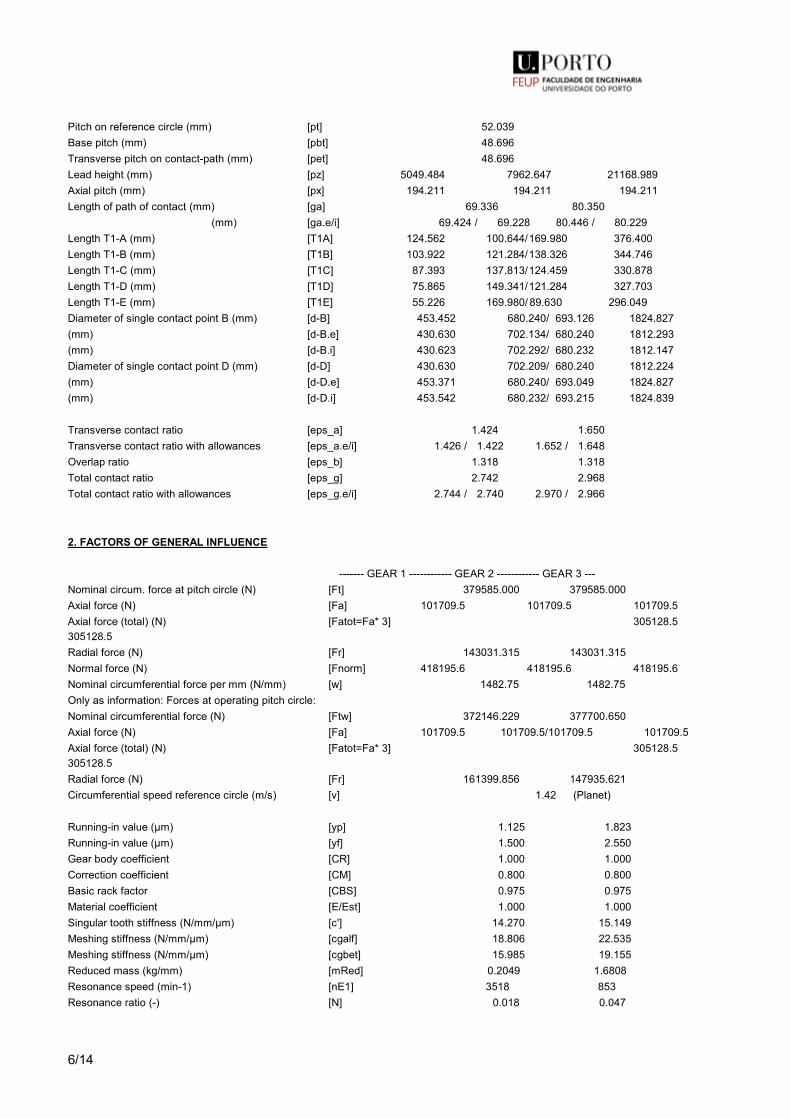
6/14
Pitch on reference circle (mm) [pt] 52.039Base pitch (mm) [pbt] 48.696Transverse pitch on contact-path (mm) [pet] 48.696Lead height (mm) [pz] 5049.484 7962.647 21168.989Axial pitch (mm) [px] 194.211 194.211 194.211Length of path of contact (mm) [ga] 69.336 80.350 (mm) [ga.e/i] 69.424 / 69.228 80.446 / 80.229Length T1-A (mm) [T1A] 124.562 100.644/ 169.980 376.400Length T1-B (mm) [T1B] 103.922 121.284/ 138.326 344.746Length T1-C (mm) [T1C] 87.393 137.813/ 124.459 330.878Length T1-D (mm) [T1D] 75.865 149.341/ 121.284 327.703Length T1-E (mm) [T1E] 55.226 169.980/ 89.630 296.049Diameter of single contact point B (mm) [d-B] 453.452 680.240/ 693.126 1824.827(mm) [d-B.e] 430.630 702.134/ 680.240 1812.293(mm) [d-B.i] 430.623 702.292/ 680.232 1812.147Diameter of single contact point D (mm) [d-D] 430.630 702.209/ 680.240 1812.224(mm) [d-D.e] 453.371 680.240/ 693.049 1824.827(mm) [d-D.i] 453.542 680.232/ 693.215 1824.839
Transverse contact ratio [eps_a] 1.424 1.650Transverse contact ratio with allowances [eps_a.e/i] 1.426 / 1.422 1.652 / 1.648Overlap ratio [eps_b] 1.318 1.318Total contact ratio [eps_g] 2.742 2.968Total contact ratio with allowances [eps_g.e/i] 2.744 / 2.740 2.970 / 2.966
2. FACTORS OF GENERAL INFLUENCE
------- GEAR 1 ------------ GEAR 2 ------------ GEAR 3 ---Nominal circum. force at pitch circle (N) [Ft] 379585.000 379585.000Axial force (N) [Fa] 101709.5 101709.5 101709.5Axial force (total) (N) [Fatot=Fa* 3] 305128.5 305128.5Radial force (N) [Fr] 143031.315 143031.315Normal force (N) [Fnorm] 418195.6 418195.6 418195.6Nominal circumferential force per mm (N/mm) [w] 1482.75 1482.75Only as information: Forces at operating pitch circle:Nominal circumferential force (N) [Ftw] 372146.229 377700.650Axial force (N) [Fa] 101709.5 101709.5/ 101709.5 101709.5Axial force (total) (N) [Fatot=Fa* 3] 305128.5 305128.5Radial force (N) [Fr] 161399.856 147935.621Circumferential speed reference circle (m/s) [v] 1.42 (Planet)
Running-in value (µm) [yp] 1.125 1.823Running-in value (µm) [yf] 1.500 2.550Gear body coefficient [CR] 1.000 1.000Correction coefficient [CM] 0.800 0.800Basic rack factor [CBS] 0.975 0.975Material coefficient [E/Est] 1.000 1.000Singular tooth stiffness (N/mm/µm) [c'] 14.270 15.149Meshing stiffness (N/mm/µm) [cgalf] 18.806 22.535Meshing stiffness (N/mm/µm) [cgbet] 15.985 19.155Reduced mass (kg/mm) [mRed] 0.2049 1.6808Resonance speed (min-1) [nE1] 3518 853Resonance ratio (-) [N] 0.018 0.047
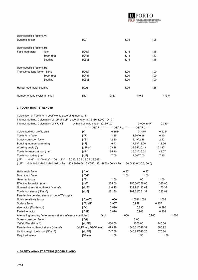
7/14
User specified factor KV:Dynamic factor [KV] 1.05 1.05
User specified factor KHb:Face load factor - flank [KHb] 1.15 1.15 - Tooth root [KFb] 1.13 1.13 - Scuffing [KBb] 1.15 1.15
User specified factor KHa:Transverse load factor - flank [KHa] 1.00 1.00 - Tooth root [KFa] 1.00 1.00 - Scuffing [KBa] 1.00 1.00
Helical load factor scuffing [Kbg] 1.26 1.28
Number of load cycles (in mio.) [NL] 1983.1 419.2 473.0
3. TOOTH ROOT STRENGTH
Calculation of Tooth form coefficients according method: BInternal toothing: Calculation of roF and sFn according to ISO 6336-3:2007-04-01Internal toothing: Calculation of YF, YS with pinion type cutter (z0= 35, x0= 0.000, rofP*= 0.380) ------- GEAR 1 ------------ GEAR 2 ------------ GEAR 3 ---Calculated with profile shift [x] 0.3934 0.3457 -0.5244Tooth form factor [YF] 1.25 1.30/ 0.96 0.90Stress correction factor [YS] 2.20 2.19/ 2.48 2.42Bending moment arm (mm) [hF] 16.73 17.78/ 13.00 18.50Working angle (°) [alfFen] 23.18 22.35/ 20.43 21.37Tooth thickness at root (mm) [sFn] 35.40 36.01/ 36.01 44.27Tooth root radius (mm) [roF] 7.05 7.00/ 7.00 7.95(hF* = 1.046/ 1.111/ 0.812/ 1.156 sFn* = 2.213/ 2.251/ 2.251/ 2.767)(roF* = 0.441/ 0.437/ 0.437/ 0.497 dsFn = 408.908/ 656.123/ 656.123/ -1860.406 alfsFn = 30.0/ 30.0/ 30.0/ 60.0)
Helix angle factor [Ybet] 0.87 0.87Deep tooth factor [YDT] 1.00 1.00Gear rim factor [YB] 1.00 1.00 1.00Effective facewidth (mm) [beff] 265.00 256.00/ 256.00 265.00Nominal stress at tooth root (N/mm²) [sigF0] 216.25 229.92/ 192.89 170.37Tooth root stress (N/mm²) [sigF] 281.80 299.62/ 251.37 222.01Permissible bending stress at root of Test-gearNotch sensitivity factor [YdrelT] 1.000 1.001/ 1.001 1.003Surface factor [YRrelT] 0.957 0.957 0.957size factor (Tooth root) [YX] 0.890 0.890 0.890Finite life factor [YNT] 0.878 0.906 0.904Alternating bending factor (mean stress influence coefficient) [YM] 1.000 0.700 1.000Stress correction factor [Yst] 2.00Yst*sigFlim (N/mm²) [sigFE] 1000.00 1000.00 740.00Permissible tooth root stress (N/mm²) [sigFP=sigFG/SFmin] 479.29 346.31/ 346.31 365.92Limit strength tooth root (N/mm²) [sigFG] 747.68 540.25/ 540.25 570.84Required safety [SFmin] 1.56 1.56 1.56
4. SAFETY AGAINST PITTING (TOOTH FLANK)

8/14
------- GEAR 1 ------------ GEAR 2 ------------ GEAR 3 ---Zone factor [ZH] 2.26 2.38Elasticity factor (√N/mm²) [ZE] 189.81 189.81Contact ratio factor [Zeps] 0.838 0.778Helix angle factor [Zbet] 1.017 1.017Effective facewidth (mm) [beff] 256.00 256.00Nominal contact stress (N/mm²) [sigH0] 867.67 417.31Contact stress at operating pitch circle (N/mm²) [sigHw] 999.99 480.95Single tooth contact factor [ZB,ZD] 1.00 1.00/ 1.00 1.00Contact stress (N/mm²) [sigHB, sigHD] 999.99 999.99/ 480.95 480.95
Lubrication coefficient at NL [ZL] 1.048 1.048/ 1.048 1.048Speed coefficient at NL [ZV] 0.959 0.959/ 0.959 0.959Roughness coefficient at NL [ZR] 1.046 1.046/ 1.061 1.061Material pairing coefficient at NL [ZW] 1.000 1.000/ 1.000 1.000Finite life factor [ZNT] 0.893 0.937 0.933Limited pitting is permitted: NoSize factor (flank) [ZX] 1.000 1.000 1.000Permissible contact stress (N/mm²) [sigHP=sigHG/SHmin] 1127.02 1182.05/ 1198.85 971.46Pitting stress limit (N/mm²) [sigHG] 1408.78 1477.56/ 1498.56 1214.32
Required safety [SHmin] 1.25 1.25 1.25
4b. MICROPITTING ACCORDING TO ISO/TR 15144-1:2014
Pairing Gear 1- 2:Calculation of permissible specific film thicknessLubricant load according to FVA Info sheet 54/7 10 (Oil: Castrol Optigear Synthetic X 320)Reference data FZG-C Test:Torque (Nm) [T1Ref] 265.1Line load at contact point A (N/mm) [FbbRef,A] 236.3Oil temperature (°C) [theOilRef] 60.0Tooth mass temperature (°C) [theMRef] 90.3Contact temperature (°C) [theBRef,A] 181.8Lubrication gap thickness (µm) [hRef,A] 0.130Specific film thickness in test (µm) [lamGFT] 0.260Material coefficient [WW] 1.00Permissible specific film thickness (µm) [lamGFP] 0.363
Interim results in accordance with ISO/TR 15144:2014Coefficient of friction [mym] 0.041Lubricant factor [XL] 0.800Roughness factor [XR] 0.679Tooth mass temperature (°C) [theM] 67.1Tip relief factor [XCa (A)] 1.597Loss factor [HV] 0.121Equivalent Young's modulus (N/mm²) [Er] 226374Pressure-viscosity coefficient (m²/N) [alf38] 0.01380Dynamic viscosity (Ns/m²) [etatM] 81.3Roughness average value (µm) [Ra] 0.5Calculation of speeds, load distribution and flank curvature according to method B following ISO/TR 15144-1:2014Ca taken as optimal in the calculation (0=no, 1=yes) 1 1
Pairing Gear 2- 3:Calculation of permissible specific film thicknessMaterial coefficient [WW] 0.82

9/14
Permissible specific film thickness (µm) [lamGFP] 0.300
Interim results in accordance with ISO/TR 15144:2014Coefficient of friction [mym] 0.024Lubricant factor [XL] 0.800Roughness factor [XR] 0.500Tooth mass temperature (°C) [theM] 66.0Tip relief factor [XCa (A)] 1.000Loss factor [HV] 0.036Equivalent Young's modulus (N/mm²) [Er] 226374Pressure-viscosity coefficient (m²/N) [alf38] 0.01380Dynamic viscosity (Ns/m²) [etatM] 84.9Roughness average value (µm) [Ra] 0.6Calculation of speeds, load distribution and flank curvature according to method B following ISO/TR 15144-1:2014Ca taken as optimal in the calculation (0=no, 1=yes) 1 1
5. SCUFFING LOAD CAPACITY
Calculation method according to ISO TR 13989:2000
Lubrication coefficient (for lubrication type) [XS] 1.200Scuffing test and load stage [FZGtest] FZG - Test A / 8.3 / 90 (ISO 14635 - 1) 13Multiple meshing factor [Xmp] 2.0 2.0Relative structure coefficient (Scuffing) [XWrelT] 1.000 1.000Thermal contact factor (N/mm/s^.5/K) [BM] 13.780 13.780 13.780Relevant tip relief (µm) [Ca] 105.00 105.00 105.00Optimal tip relief (µm) [Ceff] 86.73 72.38Ca taken as optimal in the calculation (0=no, 1=yes) 1 1/ 1 1Effective facewidth (mm) [beff] 256.000 256.000Applicable circumferential force/facewidth (N/mm) [wBt] 1969.468 1969.468(1) Kbg = 1.259, wBt*Kbg = 2479.319(2) Kbg = 1.281, wBt*Kbg = 2521.927Angle factor [Xalfbet] 1.021 0.991
Flash temperature-criteriaLubricant factor [XL] 0.639 0.639Tooth mass temperature (°C) [theMi] 85.32 67.65 (theMi = theoil + XS*0.47*Xmp*theflm)Average flash temperature (°C) [theflm] 18.01 2.35Scuffing temperature (°C) [theS] 323.17 323.17Coordinate gamma (point of highest temp.) [Gamma] 0.305 0.242(1) [Gamma.A]= 0.425 [Gamma.E]= -0.368(2) [Gamma.A]= 0.366 [Gamma.E]= -0.280Highest contact temp. (°C) [theB] 120.75 72.22Flash factor (°K*N^-.75*s^.5*m^-.5*mm) [XM] 50.058 50.058Approach factor [XJ] 1.000 1.000Load sharing factor [XGam] 0.825 0.735Dynamic viscosity (mPa*s) [etaM] 88.12 88.12 ( 65.0 °C)Coefficient of friction [mym] 0.057 0.046
Integral temperature-criteriaLubricant factor [XL] 0.800Tooth mass temperature (°C) [theMC] 78.07 66.02 (theMC = theoil + XS*0.70*theflaint)Mean flash temperature (°C) [theflaint] 7.78 0.61Integral scuffing temperature (°C) [theSint] 342.30 342.30

10/14
Flash factor (°K*N^-.75*s^.5*m^-.5*mm) [XM] 50.058 50.058Running-in factor (well run in) [XE] 1.000 1.000Contact ratio factor [Xeps] 0.284 0.235Dynamic viscosity (mPa*s) [etaOil] 88.12 88.12Mean coefficient of friction [mym] 0.041 0.024Geometry factor [XBE] 0.245 0.047Meshing factor [XQ] 1.000 1.000Tip relief factor [XCa] 1.597 1.845Integral tooth flank temperature (°C) [theint] 89.75 66.94
6. MEASUREMENTS FOR TOOTH THICKNESS
------- GEAR 1 ------------ GEAR 2 ------------ GEAR 3 ---Tooth thickness deviation DIN 3967 cd25 DIN 3967 cd25 DIN 3967 cd25Tooth thickness allowance (normal section) (mm) [As.e/i] -0.130/ -0.190 -0.175/ -0.255 -0.320/ -0.450
Number of teeth spanned [k] 4.000 6.000 -0.000(Internal toothing: k = (Measurement gap number)Base tangent length (no backlash) (mm) [Wk] 176.057 273.714 -0.000Actual base tangent length ('span') (mm) [Wk.e/i] 175.935/ 175.878 273.549/ 273.474 -0.000/ -0.000Diameter of contact point (mm) [dMWk.m] 437.644 688.673 -0.000
Theoretical diameter of ball/pin (mm) [DM] 29.430 28.203 26.867Effective diameter of ball/pin (mm) [DMeff] 30.000 30.000 28.000Radial single-ball measurement backlash free (mm) [MrK] 243.554 367.812 890.728Radial single-ball measurement (mm) [MrK.e/i] 243.420/ 243.358 367.617/ 367.527 891.160/ 891.336Diameter of contact point (mm) [dMMr.m] 443.825 693.032 1820.432Diametral measurement over two balls without clearance (mm) [MdK] 487.107 735.106 1781.268Diametral two ball measure (mm) [MdK.e/i] 486.840/ 486.717 734.716/ 734.537 1782.133/ 1782.483Measurement over pins according to DIN 3960 (mm) [MdR.e/i] 486.840/ 486.717 735.233/ 735.054 -0.000/ -0.000Measurement over 2 pins (free) according to AGMA 2002 (mm) [dk2f.e/i] 0.000/ 0.000 734.672/ 734.494 0.000/ 0.000Measurement over 2 pins (transverse) according to AGMA 2002 (mm) [dk2t.e/i] 0.000/ 0.000 735.742/ 735.563 0.000/ 0.000Measurement over 3 pins (axial) according to AGMA 2002 (mm) [dk3A.e/i] 486.840/ 486.717 735.233/ 735.054 -0.000/ -0.000Effective dimensions over 3 pins (mm) [Md3R.e/i] 0.000/ 0.000 0.000/ 0.000 -0.000/ -0.000Note: Internal gears with helical teeth cannot be measured with rollers.
Tooth thickness (chordal) in pitch diameter (mm) [sc] 29.694 29.151 19.025 (mm) [sc.e/i] 29.564/ 29.504 28.976/ 28.896 18.705/ 18.575Reference chordal height from da.m (mm) [ha] 22.036 21.087 7.561Tooth thickness (Arc) (mm) [sn] 29.715 29.159 19.026 (mm) [sn.e/i] 29.585/ 29.525 28.984/ 28.904 18.706/ 18.576
Backlash free center distance (mm) [aControl.e/i] 565.628/ 565.457 566.655/ 566.931Backlash free center distance, allowances (mm) [jta] -0.372/ -0.543 0.655/ 0.931
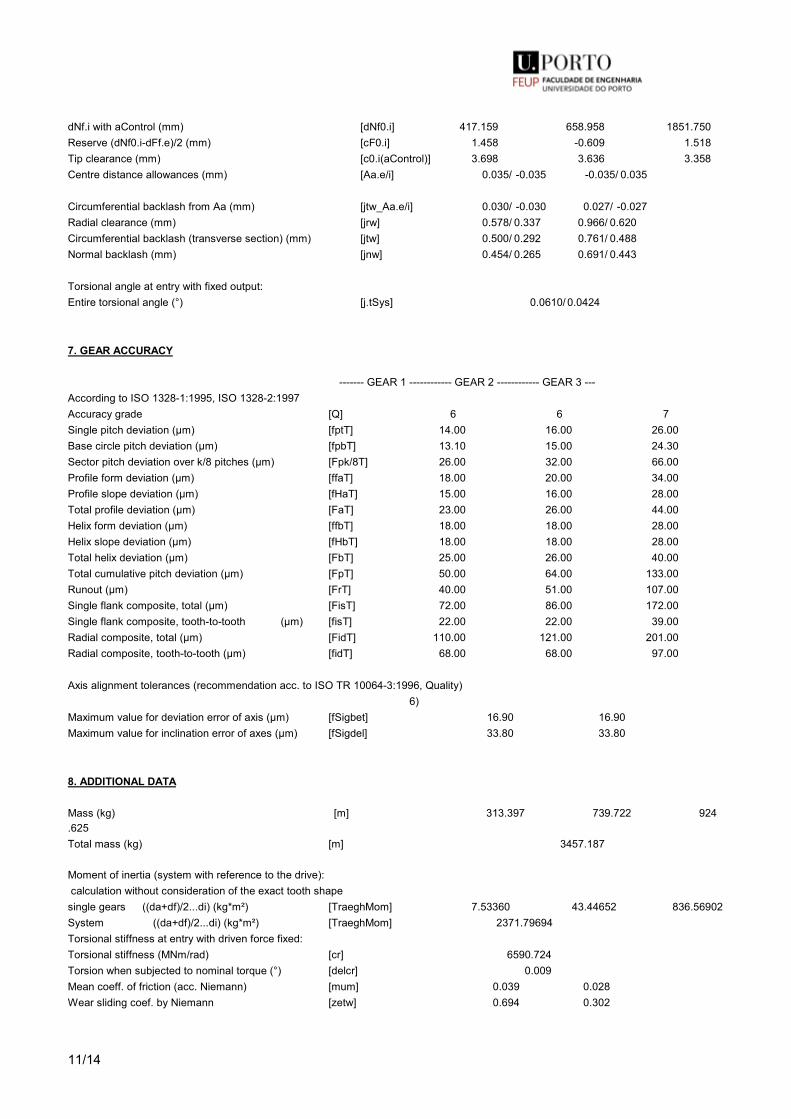
11/14
dNf.i with aControl (mm) [dNf0.i] 417.159 658.958 1851.750Reserve (dNf0.i-dFf.e)/2 (mm) [cF0.i] 1.458 -0.609 1.518Tip clearance (mm) [c0.i(aControl)] 3.698 3.636 3.358Centre distance allowances (mm) [Aa.e/i] 0.035/ -0.035 -0.035/ 0.035
Circumferential backlash from Aa (mm) [jtw_Aa.e/i] 0.030/ -0.030 0.027/ -0.027Radial clearance (mm) [jrw] 0.578/ 0.337 0.966/ 0.620Circumferential backlash (transverse section) (mm) [jtw] 0.500/ 0.292 0.761/ 0.488Normal backlash (mm) [jnw] 0.454/ 0.265 0.691/ 0.443
Torsional angle at entry with fixed output:Entire torsional angle (°) [j.tSys] 0.0610/ 0.0424
7. GEAR ACCURACY
------- GEAR 1 ------------ GEAR 2 ------------ GEAR 3 ---According to ISO 1328-1:1995, ISO 1328-2:1997Accuracy grade [Q] 6 6 7Single pitch deviation (µm) [fptT] 14.00 16.00 26.00Base circle pitch deviation (µm) [fpbT] 13.10 15.00 24.30Sector pitch deviation over k/8 pitches (µm) [Fpk/8T] 26.00 32.00 66.00Profile form deviation (µm) [ffaT] 18.00 20.00 34.00Profile slope deviation (µm) [fHaT] 15.00 16.00 28.00Total profile deviation (µm) [FaT] 23.00 26.00 44.00Helix form deviation (µm) [ffbT] 18.00 18.00 28.00Helix slope deviation (µm) [fHbT] 18.00 18.00 28.00Total helix deviation (µm) [FbT] 25.00 26.00 40.00Total cumulative pitch deviation (µm) [FpT] 50.00 64.00 133.00Runout (µm) [FrT] 40.00 51.00 107.00Single flank composite, total (µm) [FisT] 72.00 86.00 172.00Single flank composite, tooth-to-tooth (µm) [fisT] 22.00 22.00 39.00Radial composite, total (µm) [FidT] 110.00 121.00 201.00Radial composite, tooth-to-tooth (µm) [fidT] 68.00 68.00 97.00
Axis alignment tolerances (recommendation acc. to ISO TR 10064-3:1996, Quality) 6)Maximum value for deviation error of axis (µm) [fSigbet] 16.90 16.90Maximum value for inclination error of axes (µm) [fSigdel] 33.80 33.80
8. ADDITIONAL DATA
Mass (kg) [m] 313.397 739.722 924.625Total mass (kg) [m] 3457.187
Moment of inertia (system with reference to the drive): calculation without consideration of the exact tooth shapesingle gears ((da+df)/2...di) (kg*m²) [TraeghMom] 7.53360 43.44652 836.56902System ((da+df)/2...di) (kg*m²) [TraeghMom] 2371.79694Torsional stiffness at entry with driven force fixed:Torsional stiffness (MNm/rad) [cr] 6590.724Torsion when subjected to nominal torque (°) [delcr] 0.009Mean coeff. of friction (acc. Niemann) [mum] 0.039 0.028Wear sliding coef. by Niemann [zetw] 0.694 0.302
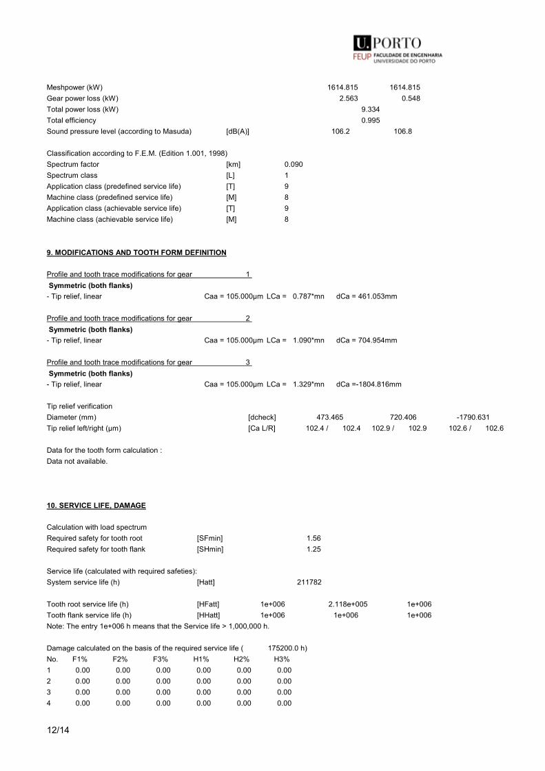
12/14
Meshpower (kW) 1614.815 1614.815Gear power loss (kW) 2.563 0.548Total power loss (kW) 9.334Total efficiency 0.995Sound pressure level (according to Masuda) [dB(A)] 106.2 106.8
Classification according to F.E.M. (Edition 1.001, 1998)Spectrum factor [km] 0.090Spectrum class [L] 1Application class (predefined service life) [T] 9Machine class (predefined service life) [M] 8Application class (achievable service life) [T] 9Machine class (achievable service life) [M] 8
9. MODIFICATIONS AND TOOTH FORM DEFINITION
Profile and tooth trace modifications for gear 1 Symmetric (both flanks)
- Tip relief, linear Caa = 105.000µm LCa = 0.787*mn dCa = 461.053mm
Profile and tooth trace modifications for gear 2 Symmetric (both flanks)
- Tip relief, linear Caa = 105.000µm LCa = 1.090*mn dCa = 704.954mm
Profile and tooth trace modifications for gear 3 Symmetric (both flanks)
- Tip relief, linear Caa = 105.000µm LCa = 1.329*mn dCa = -1804.816mm
Tip relief verificationDiameter (mm) [dcheck] 473.465 720.406 -1790.631Tip relief left/right (µm) [Ca L/R] 102.4 / 102.4 102.9 / 102.9 102.6 / 102.6
Data for the tooth form calculation :Data not available.
10. SERVICE LIFE, DAMAGE
Calculation with load spectrumRequired safety for tooth root [SFmin] 1.56Required safety for tooth flank [SHmin] 1.25
Service life (calculated with required safeties):System service life (h) [Hatt] 211782
Tooth root service life (h) [HFatt] 1e+006 2.118e+005 1e+006Tooth flank service life (h) [HHatt] 1e+006 1e+006 1e+006Note: The entry 1e+006 h means that the Service life > 1,000,000 h.
Damage calculated on the basis of the required service life ( 175200.0 h)No. F1% F2% F3% H1% H2% H3%1 0.00 0.00 0.00 0.00 0.00 0.002 0.00 0.00 0.00 0.00 0.00 0.003 0.00 0.00 0.00 0.00 0.00 0.004 0.00 0.00 0.00 0.00 0.00 0.00
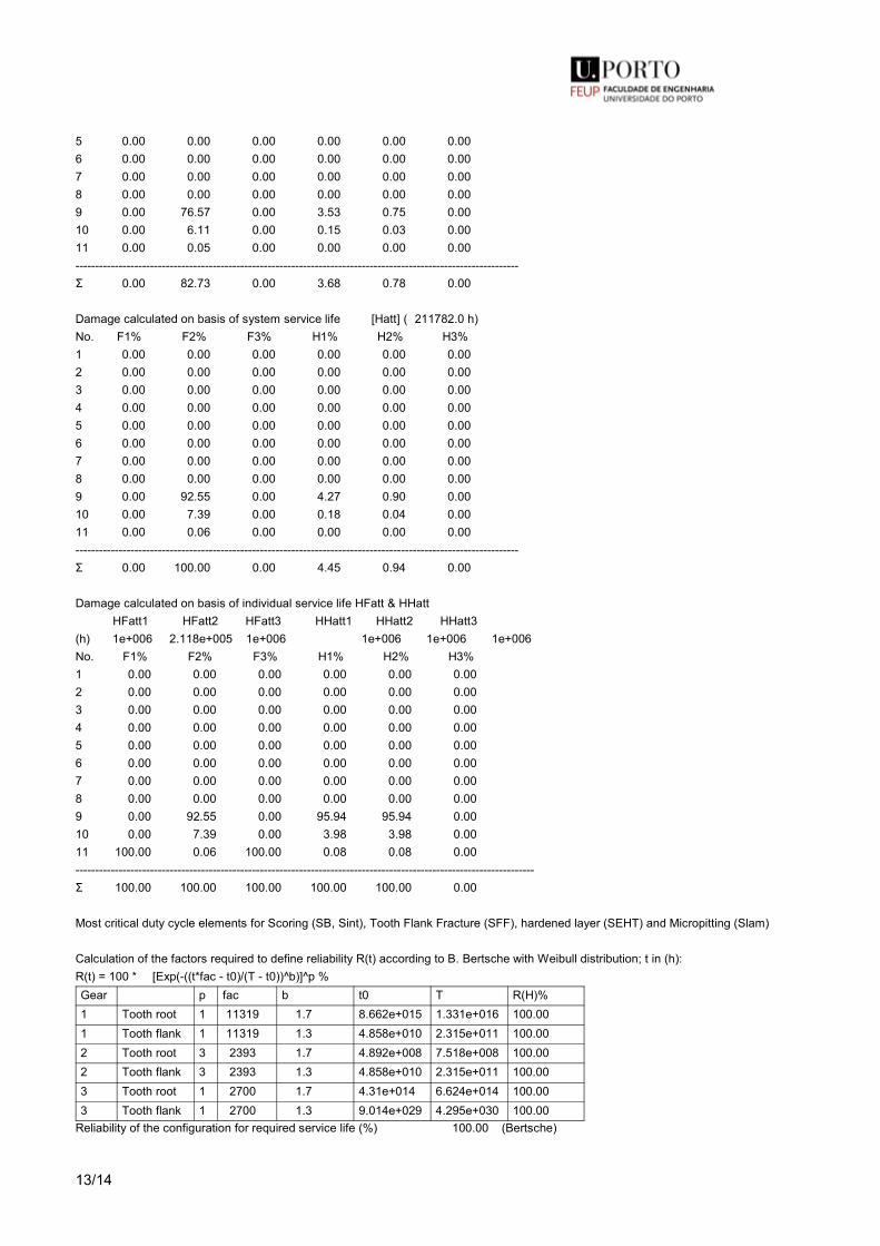
13/14
5 0.00 0.00 0.00 0.00 0.00 0.006 0.00 0.00 0.00 0.00 0.00 0.007 0.00 0.00 0.00 0.00 0.00 0.008 0.00 0.00 0.00 0.00 0.00 0.009 0.00 76.57 0.00 3.53 0.75 0.0010 0.00 6.11 0.00 0.15 0.03 0.0011 0.00 0.05 0.00 0.00 0.00 0.00-----------------------------------------------------------------------------------------------------------------Σ 0.00 82.73 0.00 3.68 0.78 0.00
Damage calculated on basis of system service life [Hatt] ( 211782.0 h)No. F1% F2% F3% H1% H2% H3%1 0.00 0.00 0.00 0.00 0.00 0.002 0.00 0.00 0.00 0.00 0.00 0.003 0.00 0.00 0.00 0.00 0.00 0.004 0.00 0.00 0.00 0.00 0.00 0.005 0.00 0.00 0.00 0.00 0.00 0.006 0.00 0.00 0.00 0.00 0.00 0.007 0.00 0.00 0.00 0.00 0.00 0.008 0.00 0.00 0.00 0.00 0.00 0.009 0.00 92.55 0.00 4.27 0.90 0.0010 0.00 7.39 0.00 0.18 0.04 0.0011 0.00 0.06 0.00 0.00 0.00 0.00-----------------------------------------------------------------------------------------------------------------Σ 0.00 100.00 0.00 4.45 0.94 0.00
Damage calculated on basis of individual service life HFatt & HHatt HFatt1 HFatt2 HFatt3 HHatt1 HHatt2 HHatt3(h) 1e+006 2.118e+005 1e+006 1e+006 1e+006 1e+006No. F1% F2% F3% H1% H2% H3%1 0.00 0.00 0.00 0.00 0.00 0.002 0.00 0.00 0.00 0.00 0.00 0.003 0.00 0.00 0.00 0.00 0.00 0.004 0.00 0.00 0.00 0.00 0.00 0.005 0.00 0.00 0.00 0.00 0.00 0.006 0.00 0.00 0.00 0.00 0.00 0.007 0.00 0.00 0.00 0.00 0.00 0.008 0.00 0.00 0.00 0.00 0.00 0.009 0.00 92.55 0.00 95.94 95.94 0.0010 0.00 7.39 0.00 3.98 3.98 0.0011 100.00 0.06 100.00 0.08 0.08 0.00---------------------------------------------------------------------------------------------------------------------Σ 100.00 100.00 100.00 100.00 100.00 0.00
Most critical duty cycle elements for Scoring (SB, Sint), Tooth Flank Fracture (SFF), hardened layer (SEHT) and Micropitting (Slam)
Calculation of the factors required to define reliability R(t) according to B. Bertsche with Weibull distribution; t in (h):R(t) = 100 * [Exp(-((t*fac - t0)/(T - t0))^b)]^p %Gear p fac b t0 T R(H)%1 Tooth root 1 11319 1.7 8.662e+015 1.331e+016 100.001 Tooth flank 1 11319 1.3 4.858e+010 2.315e+011 100.002 Tooth root 3 2393 1.7 4.892e+008 7.518e+008 100.002 Tooth flank 3 2393 1.3 4.858e+010 2.315e+011 100.003 Tooth root 1 2700 1.7 4.31e+014 6.624e+014 100.003 Tooth flank 1 2700 1.3 9.014e+029 4.295e+030 100.00
Reliability of the configuration for required service life (%) 100.00 (Bertsche)
14/14
REMARKS:- Specifications with [.e/i] imply: Maximum [e] and Minimal value [i] with consideration of all tolerances Specifications with [.m] imply: Mean value within tolerance- For the backlash tolerance, the center distance tolerances and the tooth thicknessdeviation are taken into account. Shown is the maximal and the minimal backlash corresponding the largest resp. the smallest allowances The calculation is done for the operating pitch circle.- Calculation of Zbet according Corrigendum 1 ISO 6336-2:2008 with Zbet = 1/(COS(beta)^0.5)- Details of calculation method: cg according to method B- The logarithmically interpolated value taken from the values for the fatigue strength and the static strength, based on the number of load cycles, is used for coefficients ZL, ZV, ZR, ZW, ZX, YdrelT, YRrelT and YX.. End of Report lines: 725

A.1. KISSsoft Reports - Gearing calculation
A.1.2 KISSsoft Report - Second stage
123

A. KISSsoft Reports
124

1/12
KISSsoft Release 03/2017 A KISSsoft University license - Universidade do Porto File Name : UnnamedChanged by: Joana Mêda de Sousa on: 24.09.2017 at: 05:12:43
Important hint: At least one warning has occurred during the calculation:
1-> Special load spectrum:Elements with power = 0 or speed = 0 are not usual!(Element no. 4)
2-> Notice to gear 2:NOT POSSIBLE TO MEASURE BASE TANGENT LENGTH!The width of the gear is too small, hence the tooth thickness too big,so that the required length for the measurement exceed the face width.
CALCULATION OF A HELICAL GEAR PAIR
Drawing or article number:Gear 1: IMGSUPROT(LSIMSUPPGCT)Gear 2: LSGGEN(LSIMSUPPGCT)
Load spectrum
Own InputNumber of bins in the load spectrum: 11Reference gear: 2
Bin Frequency Power Speed Torque Coefficients TemperatureNo. [%] [kW] [1/min] [Nm] KV KHβ KHα Kγ YM1 YM2 OilTemp1 0.00124 -610.0002 77.9 -74791.0611 1.0500 1.1500 1.0000 1.0000 1.0000 1.0000 652 0.00103 -380.0001 77.9 -46591.1528 1.0500 1.1500 1.0000 1.0000 1.0000 1.0000 653 0.01066 -230.0001 77.9 -28199.9083 1.0500 1.1500 1.0000 1.0000 1.0000 1.0000 654 9.39362 0.0000 77.9 0.0000 1.0000 1.0000 0.0000 1.0000 1.0000 1.0000 05 27.24773 230.0001 77.9 28199.9083 1.0500 1.1500 1.0000 1.0000 1.0000 1.0000 656 19.30359 450.0002 77.9 55173.7336 1.0500 1.1500 1.0000 1.0000 1.0000 1.0000 657 13.09509 680.0002 77.9 83373.6419 1.0500 1.1500 1.0000 1.0000 1.0000 1.0000 658 23.13569 980.0004 77.9 120156.1310 1.0500 1.1500 1.0000 1.0000 1.0000 1.0000 659 7.79235 1210.0004 77.9 148356.0393 1.0500 1.1500 1.0000 1.0000 1.0000 1.0000 6510 0.01894 1440.0005 77.9 176555.9475 1.0500 1.1500 1.0000 1.0000 1.0000 1.0000 6511 0.00006 1670.0006 77.9 204755.8558 1.0500 1.1500 1.0000 1.0000 1.0000 1.0000 65
Notice:- Tooth flank with load spectrum: Check both cases and document the unfavorable case- Tooth root with load spectrum: Check both cases and document the more realistic case (DIN3990-6, Method C) Is only applied on load spectrum bins, where the alternating bending factor (mean stress influence factor) YM=1.0.
S-N curve (Woehler line) in the endurance domain according: according to standard

2/12
Results
Safeties, calculated with load spectrum:Root safety 1.696 1.560Flank safety 1.287 1.286
Safeties against scuffing/micropitting/EHT/TFF are indicated for the most critical element of the load spectrum:Scuffing safety (integral temperature) 4.177Scuffing safety (flash temperature) 1.918Safety against micropitting (B) 1.071
Safeties, calculated with nominal torque:Safety against micropitting (B) 1.410
Analysis of critical elements in load spectrum: See section 10
ONLY AS INFORMATION: CALCULATION WITH REFERENCE POWER
Calculation method DIN 3990:1987 Method B
------- GEAR 1 -------- GEAR 2 --
Power (kW) [P] 1000.000Speed (1/min) [n] 373.8 77.9Torque (Nm) [T] 25543.4 122608.3Application factor [KA] 1.00Required service life (h) [H] 175200.00Gear driving (+) / driven (-) - +Working flank gear 1: Right flankSense of rotation gear 1 counterclockwise
1. TOOTH GEOMETRY AND MATERIAL
(geometry calculation according to ISO 21771:2007, DIN ISO 21771) ------- GEAR 1 -------- GEAR 2 --Center distance (mm) [a] 642.500Centre distance tolerance ISO 286:2010 Measure js7Normal module (mm) [mn] 8.0000Pressure angle at normal section (°) [alfn] 20.0000Helix angle at reference circle (°) [beta] 25.0000Number of teeth [z] 25 120Double helical gearing right/left left/rightTotal facewidth of Gear (mm) [b] 188.00 188.00 Width of intermediate groove (mm) [bNut] 40.00Facewidth for calculation (mm) [beH] 74.00 74.00Accuracy grade [Q-DIN 3961:1978] 6 6Inner diameter (mm) [di] 0.00 0.00Inner diameter of gear rim (mm) [dbi] 0.00 0.00
MaterialGear 1: 18CrNiMo7-6, Case-carburized steel, case-hardened

3/12
ISO 6336-5 Figure 9/10 (MQ), Core hardness >=30HRCGear 2: 18CrNiMo7-6, Case-carburized steel, case-hardened ISO 6336-5 Figure 9/10 (MQ), Core hardness >=30HRC ------- GEAR 1 -------- GEAR 2 --Surface hardness HRC 61 HRC 61Fatigue strength. tooth root stress (N/mm²) [σFlim] 500.00 500.00Fatigue strength for Hertzian pressure (N/mm²) [σHlim] 1500.00 1500.00Tensile strength (N/mm²) [σB] 1200.00 1200.00Yield point (N/mm²) [σS] 850.00 850.00Young's modulus (N/mm²) [E] 206000 206000Poisson's ratio [ν] 0.300 0.300Roughness average value DS, flank (µm) [RAH] 0.60 0.60Roughness average value DS, root (µm) [RAF] 3.00 3.00Mean roughness height, Rz, flank (µm) [RZH] 4.80 4.80Mean roughness height, Rz, root (µm) [RZF] 20.00 20.00
Gear reference profile 1 :Reference profile 1.25 / 0.38 / 1.0 ISO 53:1998 Profil ADedendum coefficient [hfP*] 1.250Root radius factor [rhofP*] 0.380 (rhofPmax*= 0.472)Addendum coefficient [haP*] 1.000Tip radius factor [rhoaP*] 0.000Protuberance height coefficient [hprP*] 0.000Protuberance angle [alfprP] 0.000Tip form height coefficient [hFaP*] 0.000Ramp angle [alfKP] 0.000 not topping
Gear reference profile 2 :Reference profile 1.25 / 0.38 / 1.0 ISO 53:1998 Profil ADedendum coefficient [hfP*] 1.250Root radius factor [rhofP*] 0.380 (rhofPmax*= 0.472)Addendum coefficient [haP*] 1.000Tip radius factor [rhoaP*] 0.000Protuberance height coefficient [hprP*] 0.000Protuberance angle [alfprP] 0.000Tip form height coefficient [hFaP*] 0.000Ramp angle [alfKP] 0.000 not topping
Summary of reference profile gears:Dedendum reference profile [hfP*] 1.250 1.250Tooth root radius Refer. profile [rofP*] 0.380 0.380Addendum Reference profile [haP*] 1.000 1.000Protuberance height coefficient [hprP*] 0.000 0.000Protuberance angle (°) [alfprP] 0.000 0.000Tip form height coefficient [hFaP*] 0.000 0.000Ramp angle (°) [alfKP] 0.000 0.000
Type of profile modification: for high load capacity gearboxeTip relief (µm) [Ca] 80.0 80.0
Lubrication type Oil injection lubricationType of oil (Own input) Oil: Castrol Optigear Synthetic X 320Lubricant base Synthetic oil based on PolyalphaolefinKinem. viscosity oil at 40 °C (mm²/s) [nu40] 325.00
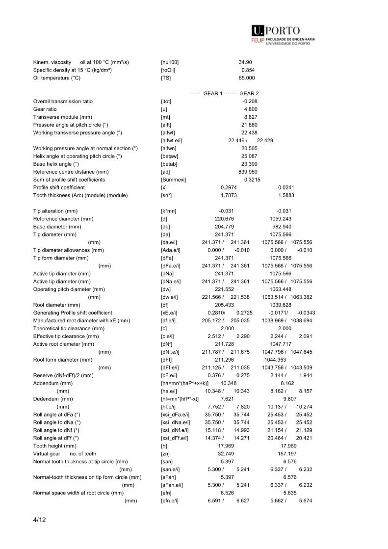
4/12
Kinem. viscosity oil at 100 °C (mm²/s) [nu100] 34.90Specific density at 15 °C (kg/dm³) [roOil] 0.854Oil temperature (°C) [TS] 65.000
------- GEAR 1 -------- GEAR 2 --Overall transmission ratio [itot] -0.208Gear ratio [u] 4.800Transverse module (mm) [mt] 8.827Pressure angle at pitch circle (°) [alft] 21.880Working transverse pressure angle (°) [alfwt] 22.438 [alfwt.e/i] 22.446 / 22.429Working pressure angle at normal section (°) [alfwn] 20.505Helix angle at operating pitch circle (°) [betaw] 25.087Base helix angle (°) [betab] 23.399Reference centre distance (mm) [ad] 639.959Sum of profile shift coefficients [Summexi] 0.3215Profile shift coefficient [x] 0.2974 0.0241Tooth thickness (Arc) (module) (module) [sn*] 1.7873 1.5883
Tip alteration (mm) [k*mn] -0.031 -0.031Reference diameter (mm) [d] 220.676 1059.243Base diameter (mm) [db] 204.779 982.940Tip diameter (mm) [da] 241.371 1075.566 (mm) [da.e/i] 241.371 / 241.361 1075.566 / 1075.556Tip diameter allowances (mm) [Ada.e/i] 0.000 / -0.010 0.000 / -0.010Tip form diameter (mm) [dFa] 241.371 1075.566 (mm) [dFa.e/i] 241.371 / 241.361 1075.566 / 1075.556Active tip diameter (mm) [dNa] 241.371 1075.566Active tip diameter (mm) [dNa.e/i] 241.371 / 241.361 1075.566 / 1075.556Operating pitch diameter (mm) [dw] 221.552 1063.448 (mm) [dw.e/i] 221.566 / 221.538 1063.514 / 1063.382Root diameter (mm) [df] 205.433 1039.628Generating Profile shift coefficient [xE.e/i] 0.2810/ 0.2725 -0.0171/ -0.0343Manufactured root diameter with xE (mm) [df.e/i] 205.172 / 205.035 1038.969 / 1038.694Theoretical tip clearance (mm) [c] 2.000 2.000Effective tip clearance (mm) [c.e/i] 2.512 / 2.290 2.244 / 2.091Active root diameter (mm) [dNf] 211.728 1047.717 (mm) [dNf.e/i] 211.787 / 211.675 1047.796 / 1047.645Root form diameter (mm) [dFf] 211.296 1044.353 (mm) [dFf.e/i] 211.125 / 211.035 1043.756 / 1043.509Reserve (dNf-dFf)/2 (mm) [cF.e/i] 0.376 / 0.275 2.144 / 1.944Addendum (mm) [ha=mn*(haP*+x+k)] 10.348 8.162 (mm) [ha.e/i] 10.348 / 10.343 8.162 / 8.157Dedendum (mm) [hf=mn*(hfP*-x)] 7.621 9.807 (mm) [hf.e/i] 7.752 / 7.820 10.137 / 10.274Roll angle at dFa (°) [xsi_dFa.e/i] 35.750 / 35.744 25.453 / 25.452Roll angle to dNa (°) [xsi_dNa.e/i] 35.750 / 35.744 25.453 / 25.452Roll angle to dNf (°) [xsi_dNf.e/i] 15.118 / 14.993 21.154 / 21.129Roll angle at dFf (°) [xsi_dFf.e/i] 14.374 / 14.271 20.464 / 20.421Tooth height (mm) [h] 17.969 17.969Virtual gear no. of teeth [zn] 32.749 157.197Normal tooth thickness at tip circle (mm) [san] 5.397 6.576 (mm) [san.e/i] 5.300 / 5.241 6.337 / 6.232Normal-tooth thickness on tip form circle (mm) [sFan] 5.397 6.576 (mm) [sFan.e/i] 5.300 / 5.241 6.337 / 6.232Normal space width at root circle (mm) [efn] 6.526 5.635 (mm) [efn.e/i] 6.591 / 6.627 5.662 / 5.674
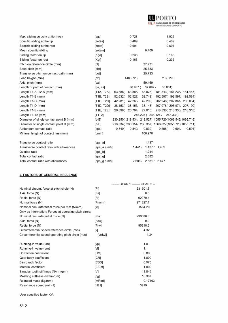
5/12
Max. sliding velocity at tip (m/s) [vga] 0.728 1.022Specific sliding at the tip [zetaa] 0.409 0.409Specific sliding at the root [zetaf] -0.691 -0.691Mean specific sliding [zetam] 0.409Sliding factor on tip [Kga] 0.236 0.168Sliding factor on root [Kgf] -0.168 -0.236Pitch on reference circle (mm) [pt] 27.731Base pitch (mm) [pbt] 25.733Transverse pitch on contact-path (mm) [pet] 25.733Lead height (mm) [pz] 1486.728 7136.296Axial pitch (mm) [px] 59.469Length of path of contact (mm) [ga, e/i] 36.987 ( 37.092 / 36.861)Length T1-A, T2-A (mm) [T1A, T2A] 63.886( 63.886/ 63.876) 181.343( 181.238/ 181.457)Length T1-B (mm) [T1B, T2B] 52.632( 52.527/ 52.749) 192.597( 192.597/ 192.584)Length T1-C (mm) [T1C, T2C] 42.281( 42.263/ 42.299) 202.948( 202.861/ 203.034)Length T1-D (mm) [T1D, T2D] 38.153( 38.153/ 38.143) 207.076( 206.971/ 207.190)Length T1-E (mm) [T1E, T2E] 26.898( 26.794/ 27.015) 218.330( 218.330/ 218.318)Length T1-T2 (mm) [T1T2] 245.228 ( 245.124 / 245.333)Diameter of single contact point B (mm) [d-B] 230.250( 218.534/ 218.527) 1055.720( 1066.545/ 1066.716)Diameter of single contact point D (mm) [d-D] 218.534( 230.154/ 230.357) 1066.627( 1055.720/ 1055.711)Addendum contact ratio [eps] 0.840( 0.840/ 0.839) 0.598( 0.601/ 0.594)Minimal length of contact line (mm) [Lmin] 108.970
Transverse contact ratio [eps_a] 1.437Transverse contact ratio with allowances [eps_a.e/m/i] 1.441 / 1.437 / 1.432Overlap ratio [eps_b] 1.244Total contact ratio [eps_g] 2.682Total contact ratio with allowances [eps_g.e/m/i] 2.686 / 2.681 / 2.677
2. FACTORS OF GENERAL INFLUENCE
------- GEAR 1 -------- GEAR 2 --Nominal circum. force at pitch circle (N) [Ft] 231501.8Axial force (N) [Fa] 0.0Radial force (N) [Fr] 92970.4Normal force (N) [Fnorm] 271827.1Nominal circumferential force per mm (N/mm) [w] 1564.20Only as information: Forces at operating pitch circle:Nominal circumferential force (N) [Ftw] 230586.3Axial force (N) [Faw] 0.0Radial force (N) [Frw] 95218.3Circumferential speed reference circle (m/s) [v] 4.32Circumferential speed operating pitch circle (m/s) [v(dw)] 4.34
Running-in value (µm) [yp] 1.0Running-in value (µm) [yf] 1.1Correction coefficient [CM] 0.800Gear body coefficient [CR] 1.000Basic rack factor [CBS] 0.975Material coefficient [E/Est] 1.000Singular tooth stiffness (N/mm/µm) [c'] 13.845Meshing stiffness (N/mm/µm) [cg] 18.387Reduced mass (kg/mm) [mRed] 0.17463Resonance speed (min-1) [nE1] 3919
User specified factor KV:

6/12
Dynamic factor [KV] 1.050
User specified factor KHb:Face load factor - flank [KHb] 1.150 - Tooth root [KFb] 1.113 - Scuffing [KBb] 1.150
User specified factor KHa:Transverse load factor - flank [KHa] 1.000 - Tooth root [KFa] 1.000 - Scuffing [KBa] 1.000
Helical load factor scuffing [Kbg] 1.251
Number of load cycles (in mio.) [NL] 3929.871 1637.446
3. TOOTH ROOT STRENGTH
Calculation of Tooth form coefficients according method: B ------- GEAR 1 -------- GEAR 2 --Calculated with profile shift [x] 0.2974 0.0241Tooth form factor [YF] 1.09 1.20Stress correction factor [YS] 2.30 2.27Working angle (°) [alfFen] 20.66 20.03Bending moment arm (mm) [hF] 7.04 8.42Tooth thickness at root (mm) [sFn] 17.58 18.35Tooth root radius (mm) [roF] 3.67 3.51(hF* = 0.881/ 1.053 sFn* = 2.198/ 2.294 roF* = 0.459/ 0.439) (den (mm) = 267.873/ 1261.821 dsFn(mm) = 208.458/ 1042.793 alfsFn(°) = 30.00/ 30.00 qs = 2.393/ 2.615)
Contact ratio factor [Yeps] 1.000Helix angle factor [Ybet] 0.792Effective facewidth (mm) [beff] 74.00 74.00Nominal stress at tooth root (N/mm²) [sigF0] 386.90 421.27Tooth root stress (N/mm²) [sigF] 451.99 492.15
Permissible bending stress at root of Test-gearNotch sensitivity factor [YdrelT] 0.999 1.001Surface factor [YRrelT] 0.957 0.957size factor (Tooth root) [YX] 0.970 0.970Finite life factor [YNT] 1.000 1.000 [YdrelT*YRrelT*YX*YNT] 0.927 0.929Alternating bending factor (mean stress influence coefficient) [YM] 1.000 1.000Stress correction factor [Yst] 2.00Yst*sigFlim (N/mm²) [sigFE] 1000.00 1000.00Permissible tooth root stress (N/mm²) [sigFP=sigFG/SFmin] 594.29 595.54Limit strength tooth root (N/mm²) [sigFG] 927.09 929.04Required safety [SFmin] 1.56 1.56
4. SAFETY AGAINST PITTING (TOOTH FLANK)
------- GEAR 1 -------- GEAR 2 --
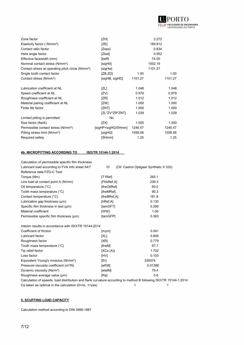
7/12
Zone factor [ZH] 2.272Elasticity factor (√N/mm²) [ZE] 189.812Contact ratio factor [Zeps] 0.834Helix angle factor [Zbet] 0.952Effective facewidth (mm) [beff] 74.00Nominal contact stress (N/mm²) [sigH0] 1002.19Contact stress at operating pitch circle (N/mm²) [sigHw] 1101.27Single tooth contact factor [ZB,ZD] 1.00 1.00Contact stress (N/mm²) [sigHB, sigHD] 1101.27 1101.27
Lubrication coefficient at NL [ZL] 1.048 1.048Speed coefficient at NL [ZV] 0.979 0.979Roughness coefficient at NL [ZR] 1.012 1.012Material pairing coefficient at NL [ZW] 1.000 1.000Finite life factor [ZNT] 1.000 1.000 [ZL*ZV*ZR*ZNT] 1.039 1.039Limited pitting is permitted: NoSize factor (flank) [ZX] 1.000 1.000Permissible contact stress (N/mm²) [sigHP=sigHG/SHmin] 1246.47 1246.47Pitting stress limit (N/mm²) [sigHG] 1558.08 1558.08Required safety [SHmin] 1.25 1.25
4b. MICROPITTING ACCORDING TO ISO/TR 15144-1:2014
Calculation of permissible specific film thicknessLubricant load according to FVA Info sheet 54/7 10 (Oil: Castrol Optigear Synthetic X 320)Reference data FZG-C Test:Torque (Nm) [T1Ref] 265.1Line load at contact point A (N/mm) [FbbRef,A] 236.3Oil temperature (°C) [theOilRef] 60.0Tooth mass temperature (°C) [theMRef] 90.3Contact temperature (°C) [theBRef,A] 181.8Lubrication gap thickness (µm) [hRef,A] 0.130Specific film thickness in test (µm) [lamGFT] 0.260Material coefficient [WW] 1.00Permissible specific film thickness (µm) [lamGFP] 0.363
Interim results in accordance with ISO/TR 15144:2014Coefficient of friction [mym] 0.041Lubricant factor [XL] 0.800Roughness factor [XR] 0.779Tooth mass temperature (°C) [theM] 67.7Tip relief factor [XCa (A)] 1.702Loss factor [HV] 0.103Equivalent Young's modulus (N/mm²) [Er] 226374Pressure-viscosity coefficient (m²/N) [alf38] 0.01380Dynamic viscosity (Ns/m²) [etatM] 79.4Roughness average value (µm) [Ra] 0.6Calculation of speeds, load distribution and flank curvature according to method B following ISO/TR 15144-1:2014Ca taken as optimal in the calculation (0=no, 1=yes) 1 1
5. SCUFFING LOAD CAPACITY
Calculation method according to DIN 3990:1987
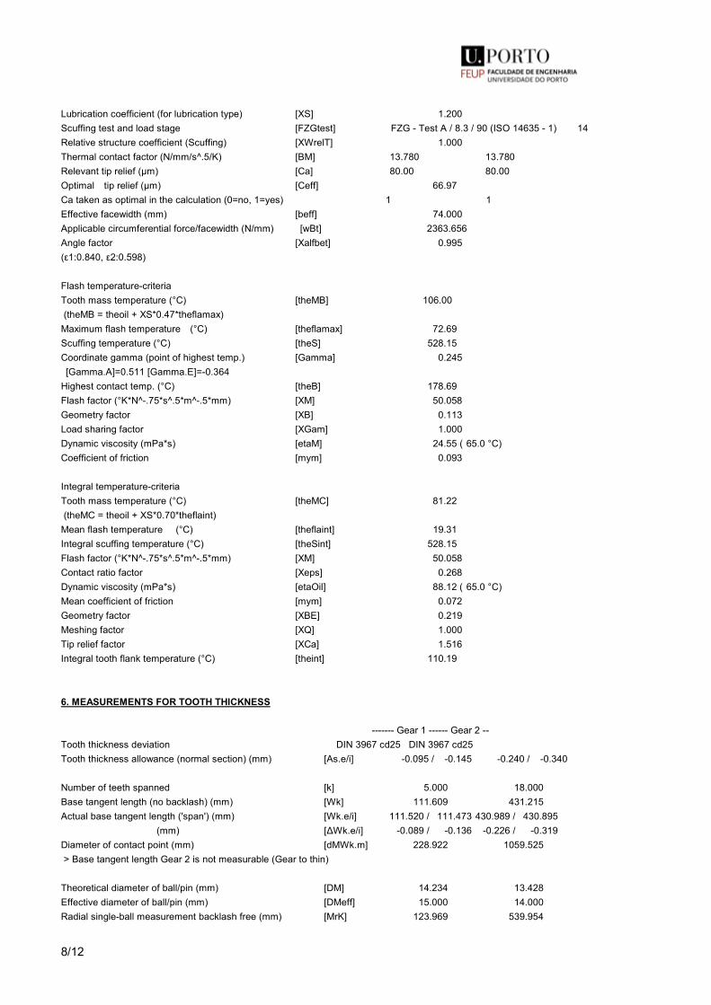
8/12
Lubrication coefficient (for lubrication type) [XS] 1.200Scuffing test and load stage [FZGtest] FZG - Test A / 8.3 / 90 (ISO 14635 - 1) 14Relative structure coefficient (Scuffing) [XWrelT] 1.000Thermal contact factor (N/mm/s^.5/K) [BM] 13.780 13.780Relevant tip relief (µm) [Ca] 80.00 80.00Optimal tip relief (µm) [Ceff] 66.97Ca taken as optimal in the calculation (0=no, 1=yes) 1 1Effective facewidth (mm) [beff] 74.000Applicable circumferential force/facewidth (N/mm) [wBt] 2363.656Angle factor [Xalfbet] 0.995(ε1: 0.840, ε2: 0.598)
Flash temperature-criteriaTooth mass temperature (°C) [theMB] 106.00 (theMB = theoil + XS*0.47*theflamax)Maximum flash temperature (°C) [theflamax] 72.69Scuffing temperature (°C) [theS] 528.15Coordinate gamma (point of highest temp.) [Gamma] 0.245 [Gamma.A]= 0.511 [Gamma.E]= -0.364Highest contact temp. (°C) [theB] 178.69Flash factor (°K*N^-.75*s^.5*m^-.5*mm) [XM] 50.058Geometry factor [XB] 0.113Load sharing factor [XGam] 1.000Dynamic viscosity (mPa*s) [etaM] 24.55 ( 65.0 °C)Coefficient of friction [mym] 0.093
Integral temperature-criteriaTooth mass temperature (°C) [theMC] 81.22 (theMC = theoil + XS*0.70*theflaint)Mean flash temperature (°C) [theflaint] 19.31Integral scuffing temperature (°C) [theSint] 528.15Flash factor (°K*N^-.75*s^.5*m^-.5*mm) [XM] 50.058Contact ratio factor [Xeps] 0.268Dynamic viscosity (mPa*s) [etaOil] 88.12 ( 65.0 °C)Mean coefficient of friction [mym] 0.072Geometry factor [XBE] 0.219Meshing factor [XQ] 1.000Tip relief factor [XCa] 1.516Integral tooth flank temperature (°C) [theint] 110.19
6. MEASUREMENTS FOR TOOTH THICKNESS
------- Gear 1 ------ Gear 2 --Tooth thickness deviation DIN 3967 cd25 DIN 3967 cd25Tooth thickness allowance (normal section) (mm) [As.e/i] -0.095 / -0.145 -0.240 / -0.340
Number of teeth spanned [k] 5.000 18.000Base tangent length (no backlash) (mm) [Wk] 111.609 431.215Actual base tangent length ('span') (mm) [Wk.e/i] 111.520 / 111.473 430.989 / 430.895 (mm) [ΔWk.e/i] -0.089 / -0.136 -0.226 / -0.319Diameter of contact point (mm) [dMWk.m] 228.922 1059.525 > Base tangent length Gear 2 is not measurable (Gear to thin)
Theoretical diameter of ball/pin (mm) [DM] 14.234 13.428Effective diameter of ball/pin (mm) [DMeff] 15.000 14.000Radial single-ball measurement backlash free (mm) [MrK] 123.969 539.954
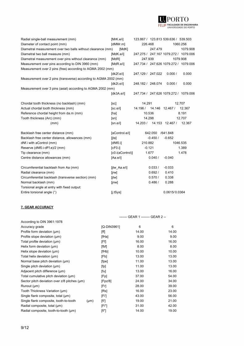
9/12
Radial single-ball measurement (mm) [MrK.e/i] 123.867 / 123.813 539.636 / 539.503Diameter of contact point (mm) [dMMr.m] 226.468 1060.256Diametral measurement over two balls without clearance (mm) [MdK] 247.479 1079.908Diametral two ball measure (mm) [MdK.e/i] 247.275 / 247.167 1079.272 / 1079.006Diametral measurement over pins without clearance (mm) [MdR] 247.939 1079.908Measurement over pins according to DIN 3960 (mm) [MdR.e/i] 247.734 / 247.626 1079.272 / 1079.006Measurement over 2 pins (free) according to AGMA 2002 (mm) [dk2f.e/i] 247.129 / 247.022 0.000 / 0.000Measurement over 2 pins (transverse) according to AGMA 2002 (mm) [dk2t.e/i] 248.182 / 248.074 0.000 / 0.000Measurement over 3 pins (axial) according to AGMA 2002 (mm) [dk3A.e/i] 247.734 / 247.626 1079.272 / 1079.006
Chordal tooth thickness (no backlash) (mm) [sc] 14.291 12.707Actual chordal tooth thickness (mm) [sc.e/i] 14.196 / 14.146 12.467 / 12.367Reference chordal height from da.m (mm) [ha] 10.536 8.191Tooth thickness (Arc) (mm) [sn] 14.298 12.707 (mm) [sn.e/i] 14.203 / 14.153 12.467 / 12.367
Backlash free center distance (mm) [aControl.e/i] 642.050 / 641.848Backlash free center distance, allowances (mm) [jta] -0.450 / -0.652dNf.i with aControl (mm) [dNf0.i] 210.882 1046.535Reserve (dNf0.i-dFf.e)/2 (mm) [cF0.i] -0.121 1.389Tip clearance (mm) [c0.i(aControl)] 1.677 1.478Centre distance allowances (mm) [Aa.e/i] 0.040 / -0.040
Circumferential backlash from Aa (mm) [jtw_Aa.e/i] 0.033 / -0.033Radial clearance (mm) [jrw] 0.692 / 0.410Circumferential backlash (transverse section) (mm) [jtw] 0.570 / 0.338Normal backlash (mm) [jnw] 0.486 / 0.288Torsional angle at entry with fixed output:Entire torsional angle (°) [j.tSys] 0.0615/ 0.0364
7. GEAR ACCURACY
------- GEAR 1 -------- GEAR 2 --According to DIN 3961:1978 Accuracy grade [Q-DIN3961] 6 6Profile form deviation (µm) [ff] 14.00 14.00Profile slope deviation (µm) [fHa] 9.00 9.00Total profile deviation (µm) [Ff] 16.00 16.00Helix form deviation (µm) [fbf] 8.00 8.00Helix slope deviation (µm) [fHb] 10.00 10.00Total helix deviation (µm) [Fb] 13.00 13.00Normal base pitch deviation (µm) [fpe] 11.00 13.00Single pitch deviation (µm) [fp] 11.00 13.00Adjacent pitch difference (µm) [fu] 13.00 16.00Total cumulative pitch deviation (µm) [Fp] 37.00 54.00Sector pitch deviation over z/8 pitches (µm) [Fpz/8] 24.00 34.00Runout (µm) [Fr] 28.00 39.00Tooth Thickness Variation (µm) [Rs] 16.00 23.00Single flank composite, total (µm) [Fi'] 43.00 56.00Single flank composite, tooth-to-tooth (µm) [fi'] 19.00 21.00Radial composite, total (µm) [Fi"] 31.00 42.00Radial composite, tooth-to-tooth (µm) [fi"] 14.00 19.00
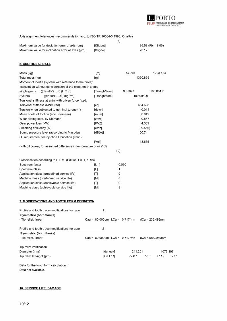
10/12
Axis alignment tolerances (recommendation acc. to ISO TR 10064-3:1996, Quality) 6)Maximum value for deviation error of axis (µm) [fSigbet] 36.58 (Fb= 18.00)Maximum value for inclination error of axes (µm) [fSigdel] 73.17
8. ADDITIONAL DATA
Mass (kg) [m] 57.701 1293.154Total mass (kg) [m] 1350.855 Moment of inertia (system with reference to the drive): calculation without consideration of the exact tooth shapesingle gears ((da+df)/2...di) (kg*m²) [TraeghMom] 0.35997 180.80111System ((da+df)/2...di) (kg*m²) [TraeghMom] 189.09490Torsional stiffness at entry with driven force fixed:Torsional stiffness (MNm/rad) [cr] 654.698Torsion when subjected to nominal torque (°) [delcr] 0.011Mean coeff. of friction (acc. Niemann) [mum] 0.042Wear sliding coef. by Niemann [zetw] 0.587Gear power loss (kW) [PVZ] 4.339(Meshing efficiency (%) [etaz] 99.566)Sound pressure level (according to Masuda) [dB(A)] 100.7Oil requirement for injection lubrication (l/min) [Voil] 13.665(with oil cooler, for assumed difference in temperature of oil (°C): 10)
Classification according to F.E.M. (Edition 1.001, 1998)Spectrum factor [km] 0.090Spectrum class [L] 1Application class (predefined service life) [T] 9Machine class (predefined service life) [M] 8Application class (achievable service life) [T] 9Machine class (achievable service life) [M] 8
9. MODIFICATIONS AND TOOTH FORM DEFINITION
Profile and tooth trace modifications for gear 1 Symmetric (both flanks)
- Tip relief, linear Caa = 80.000µm LCa = 0.717*mn dCa = 235.498mm
Profile and tooth trace modifications for gear 2 Symmetric (both flanks)
- Tip relief, linear Caa = 80.000µm LCa = 0.717*mn dCa = 1070.959mm
Tip relief verificationDiameter (mm) [dcheck] 241.201 1075.396Tip relief left/right (µm) [Ca L/R] 77.8 / 77.8 77.1 / 77.1
Data for the tooth form calculation :Data not available.
10. SERVICE LIFE, DAMAGE
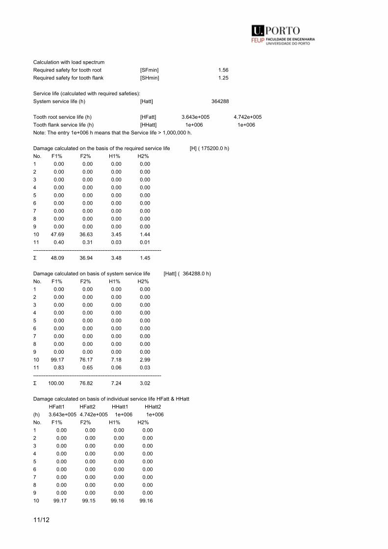
11/12
Calculation with load spectrumRequired safety for tooth root [SFmin] 1.56Required safety for tooth flank [SHmin] 1.25
Service life (calculated with required safeties):System service life (h) [Hatt] 364288
Tooth root service life (h) [HFatt] 3.643e+005 4.742e+005Tooth flank service life (h) [HHatt] 1e+006 1e+006Note: The entry 1e+006 h means that the Service life > 1,000,000 h.
Damage calculated on the basis of the required service life [H] ( 175200.0 h)No. F1% F2% H1% H2%1 0.00 0.00 0.00 0.002 0.00 0.00 0.00 0.003 0.00 0.00 0.00 0.004 0.00 0.00 0.00 0.005 0.00 0.00 0.00 0.006 0.00 0.00 0.00 0.007 0.00 0.00 0.00 0.008 0.00 0.00 0.00 0.009 0.00 0.00 0.00 0.0010 47.69 36.63 3.45 1.4411 0.40 0.31 0.03 0.01--------------------------------------------------------------------------Σ 48.09 36.94 3.48 1.45
Damage calculated on basis of system service life [Hatt] ( 364288.0 h)No. F1% F2% H1% H2%1 0.00 0.00 0.00 0.002 0.00 0.00 0.00 0.003 0.00 0.00 0.00 0.004 0.00 0.00 0.00 0.005 0.00 0.00 0.00 0.006 0.00 0.00 0.00 0.007 0.00 0.00 0.00 0.008 0.00 0.00 0.00 0.009 0.00 0.00 0.00 0.0010 99.17 76.17 7.18 2.9911 0.83 0.65 0.06 0.03--------------------------------------------------------------------------Σ 100.00 76.82 7.24 3.02
Damage calculated on basis of individual service life HFatt & HHatt HFatt1 HFatt2 HHatt1 HHatt2(h) 3.643e+005 4.742e+005 1e+006 1e+006No. F1% F2% H1% H2%1 0.00 0.00 0.00 0.002 0.00 0.00 0.00 0.003 0.00 0.00 0.00 0.004 0.00 0.00 0.00 0.005 0.00 0.00 0.00 0.006 0.00 0.00 0.00 0.007 0.00 0.00 0.00 0.008 0.00 0.00 0.00 0.009 0.00 0.00 0.00 0.0010 99.17 99.15 99.16 99.16

12/12
11 0.83 0.85 0.84 0.84--------------------------------------------------------------------Σ 100.00 100.00 100.00 100.00
Most critical duty cycle elements for Scoring (SB, Sint), Tooth Flank Fracture (SFF), hardened layer (SEHT) and Micropitting (Slam)
Calculation of the factors required to define reliability R(t) according to B. Bertsche with Weibull distribution:R(t) = 100 * Exp(-((t*fac - t0)/(T - t0))^b) %; t (h)Gear fac b t0 T R(H)%1 Tooth root 22431 1.7 7.888e+009 1.212e+010 100.001 Tooth flank 22431 1.3 1.017e+011 4.848e+011 100.002 Tooth root 9346 1.7 4.279e+009 6.576e+009 100.002 Tooth flank 9346 1.3 1.017e+011 4.848e+011 100.00
Reliability of the configuration for required service life (%) 100.00 (Bertsche)
REMARKS:- Specifications with [.e/i] imply: Maximum [e] and Minimal value [i] with consideration of all tolerances Specifications with [.m] imply: Mean value within tolerance- For the backlash tolerance, the center distance tolerances and the tooth thicknessdeviation are taken into account. Shown is the maximal and the minimal backlash corresponding the largest resp. the smallest allowances The calculation is done for the operating pitch circle.- Details of calculation method: cg according to method B End of Report lines: 638

A.1. KISSsoft Reports - Gearing calculation
A.1.3 KISSsoft Report - Third stage
137

A. KISSsoft Reports
138
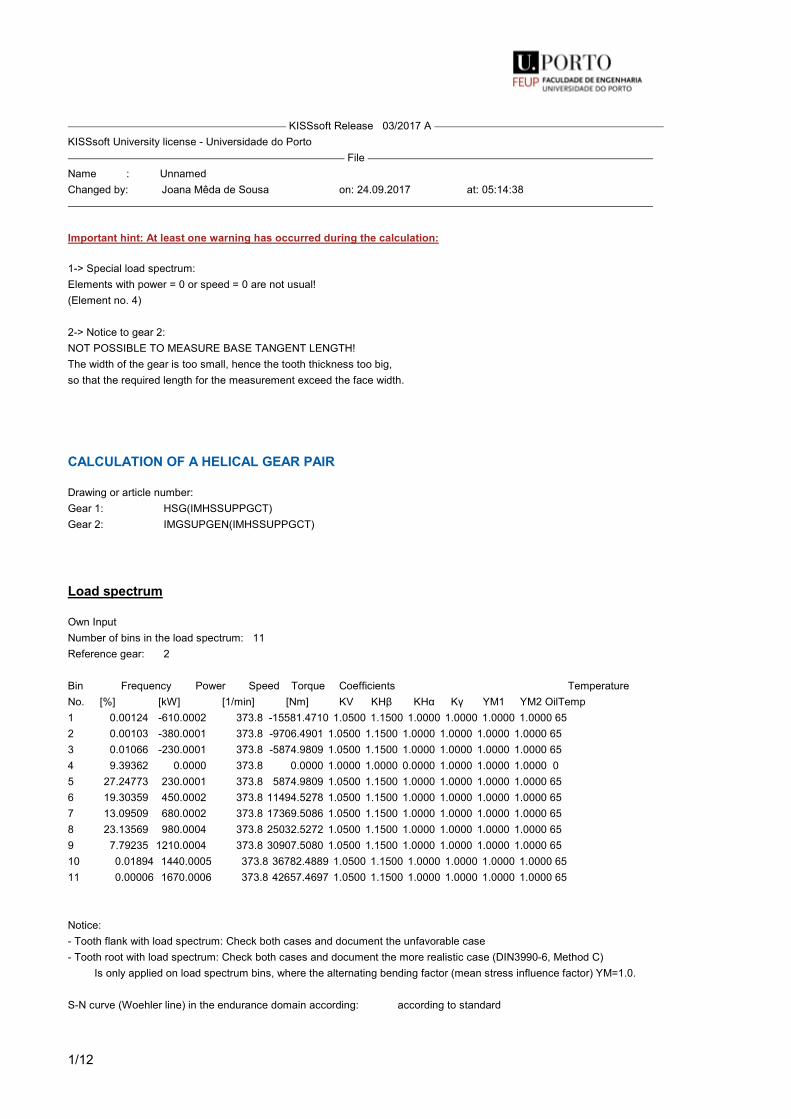
1/12
KISSsoft Release 03/2017 A KISSsoft University license - Universidade do Porto File Name : UnnamedChanged by: Joana Mêda de Sousa on: 24.09.2017 at: 05:14:38
Important hint: At least one warning has occurred during the calculation:
1-> Special load spectrum:Elements with power = 0 or speed = 0 are not usual!(Element no. 4)
2-> Notice to gear 2:NOT POSSIBLE TO MEASURE BASE TANGENT LENGTH!The width of the gear is too small, hence the tooth thickness too big,so that the required length for the measurement exceed the face width.
CALCULATION OF A HELICAL GEAR PAIR
Drawing or article number:Gear 1: HSG(IMHSSUPPGCT)Gear 2: IMGSUPGEN(IMHSSUPPGCT)
Load spectrum
Own InputNumber of bins in the load spectrum: 11Reference gear: 2
Bin Frequency Power Speed Torque Coefficients TemperatureNo. [%] [kW] [1/min] [Nm] KV KHβ KHα Kγ YM1 YM2 OilTemp1 0.00124 -610.0002 373.8 -15581.4710 1.0500 1.1500 1.0000 1.0000 1.0000 1.0000 652 0.00103 -380.0001 373.8 -9706.4901 1.0500 1.1500 1.0000 1.0000 1.0000 1.0000 653 0.01066 -230.0001 373.8 -5874.9809 1.0500 1.1500 1.0000 1.0000 1.0000 1.0000 654 9.39362 0.0000 373.8 0.0000 1.0000 1.0000 0.0000 1.0000 1.0000 1.0000 05 27.24773 230.0001 373.8 5874.9809 1.0500 1.1500 1.0000 1.0000 1.0000 1.0000 656 19.30359 450.0002 373.8 11494.5278 1.0500 1.1500 1.0000 1.0000 1.0000 1.0000 657 13.09509 680.0002 373.8 17369.5086 1.0500 1.1500 1.0000 1.0000 1.0000 1.0000 658 23.13569 980.0004 373.8 25032.5272 1.0500 1.1500 1.0000 1.0000 1.0000 1.0000 659 7.79235 1210.0004 373.8 30907.5080 1.0500 1.1500 1.0000 1.0000 1.0000 1.0000 6510 0.01894 1440.0005 373.8 36782.4889 1.0500 1.1500 1.0000 1.0000 1.0000 1.0000 6511 0.00006 1670.0006 373.8 42657.4697 1.0500 1.1500 1.0000 1.0000 1.0000 1.0000 65
Notice:- Tooth flank with load spectrum: Check both cases and document the unfavorable case- Tooth root with load spectrum: Check both cases and document the more realistic case (DIN3990-6, Method C) Is only applied on load spectrum bins, where the alternating bending factor (mean stress influence factor) YM=1.0.
S-N curve (Woehler line) in the endurance domain according: according to standard
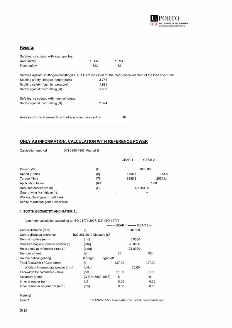
2/12
Results
Safeties, calculated with load spectrum:Root safety 1.566 1.593Flank safety 1.323 1.321
Safeties against scuffing/micropitting/EHT/TFF are indicated for the most critical element of the load spectrum:Scuffing safety (integral temperature) 3.754Scuffing safety (flash temperature) 1.995Safety against micropitting (B) 1.500
Safeties, calculated with nominal torque:Safety against micropitting (B) 2.074
Analysis of critical elements in load spectrum: See section 10
ONLY AS INFORMATION: CALCULATION WITH REFERENCE POWER
Calculation method DIN 3990:1987 Method B
------- GEAR 1 -------- GEAR 2 --
Power (kW) [P] 1000.000Speed (1/min) [n] 1495.4 373.8Torque (Nm) [T] 6385.8 25543.4Application factor [KA] 1.00Required service life (h) [H] 175200.00Gear driving (+) / driven (-) - +Working flank gear 1: Left flankSense of rotation gear 1 clockwise
1. TOOTH GEOMETRY AND MATERIAL
(geometry calculation according to ISO 21771:2007, DIN ISO 21771) ------- GEAR 1 -------- GEAR 2 --Center distance (mm) [a] 346.500Centre distance tolerance ISO 286:2010 Measure js7Normal module (mm) [mn] 5.0000Pressure angle at normal section (°) [alfn] 20.0000Helix angle at reference circle (°) [beta] 25.0000Number of teeth [z] 25 100Double helical gearing left/right right/leftTotal facewidth of Gear (mm) [b] 127.00 127.00 Width of intermediate groove (mm) [bNut] 25.00Facewidth for calculation (mm) [beH] 51.00 51.00Accuracy grade [Q-DIN 3961:1978] 6 6Inner diameter (mm) [di] 0.00 0.00Inner diameter of gear rim (mm) [dbi] 0.00 0.00
MaterialGear 1: 18CrNiMo7-6, Case-carburized steel, case-hardened
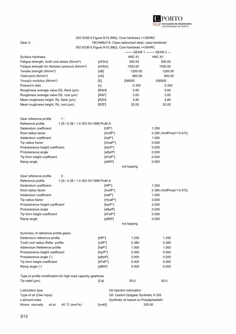
3/12
ISO 6336-5 Figure 9/10 (MQ), Core hardness >=30HRCGear 2: 18CrNiMo7-6, Case-carburized steel, case-hardened ISO 6336-5 Figure 9/10 (MQ), Core hardness >=30HRC ------- GEAR 1 -------- GEAR 2 --Surface hardness HRC 61 HRC 61Fatigue strength. tooth root stress (N/mm²) [σFlim] 500.00 500.00Fatigue strength for Hertzian pressure (N/mm²) [σHlim] 1500.00 1500.00Tensile strength (N/mm²) [σB] 1200.00 1200.00Yield point (N/mm²) [σS] 850.00 850.00Young's modulus (N/mm²) [E] 206000 206000Poisson's ratio [ν] 0.300 0.300Roughness average value DS, flank (µm) [RAH] 0.60 0.60Roughness average value DS, root (µm) [RAF] 3.00 3.00Mean roughness height, Rz, flank (µm) [RZH] 4.80 4.80Mean roughness height, Rz, root (µm) [RZF] 20.00 20.00
Gear reference profile 1 :Reference profile 1.25 / 0.38 / 1.0 ISO 53:1998 Profil ADedendum coefficient [hfP*] 1.250Root radius factor [rhofP*] 0.380 (rhofPmax*= 0.472)Addendum coefficient [haP*] 1.000Tip radius factor [rhoaP*] 0.000Protuberance height coefficient [hprP*] 0.000Protuberance angle [alfprP] 0.000Tip form height coefficient [hFaP*] 0.000Ramp angle [alfKP] 0.000 not topping
Gear reference profile 2 :Reference profile 1.25 / 0.38 / 1.0 ISO 53:1998 Profil ADedendum coefficient [hfP*] 1.250Root radius factor [rhofP*] 0.380 (rhofPmax*= 0.472)Addendum coefficient [haP*] 1.000Tip radius factor [rhoaP*] 0.000Protuberance height coefficient [hprP*] 0.000Protuberance angle [alfprP] 0.000Tip form height coefficient [hFaP*] 0.000Ramp angle [alfKP] 0.000 not topping
Summary of reference profile gears:Dedendum reference profile [hfP*] 1.250 1.250Tooth root radius Refer. profile [rofP*] 0.380 0.380Addendum Reference profile [haP*] 1.000 1.000Protuberance height coefficient [hprP*] 0.000 0.000Protuberance angle (°) [alfprP] 0.000 0.000Tip form height coefficient [hFaP*] 0.000 0.000Ramp angle (°) [alfKP] 0.000 0.000
Type of profile modification: for high load capacity gearboxeTip relief (µm) [Ca] 50.0 50.0
Lubrication type Oil injection lubricationType of oil (Own input) Oil: Castrol Optigear Synthetic X 320Lubricant base Synthetic oil based on PolyalphaolefinKinem. viscosity oil at 40 °C (mm²/s) [nu40] 325.00

4/12
Kinem. viscosity oil at 100 °C (mm²/s) [nu100] 34.90Specific density at 15 °C (kg/dm³) [roOil] 0.854Oil temperature (°C) [TS] 65.000
------- GEAR 1 -------- GEAR 2 --Overall transmission ratio [itot] -0.250Gear ratio [u] 4.000Transverse module (mm) [mt] 5.517Pressure angle at pitch circle (°) [alft] 21.880Working transverse pressure angle (°) [alfwt] 22.568 [alfwt.e/i] 22.579 / 22.556Working pressure angle at normal section (°) [alfwn] 20.623Helix angle at operating pitch circle (°) [betaw] 25.108Base helix angle (°) [betab] 23.399Reference centre distance (mm) [ad] 344.806Sum of profile shift coefficients [Summexi] 0.3440Profile shift coefficient [x] 0.2964 0.0476Tooth thickness (Arc) (module) (module) [sn*] 1.7866 1.6054
Tip alteration (mm) [k*mn] -0.025 -0.025Reference diameter (mm) [d] 137.922 551.689Base diameter (mm) [db] 127.987 511.948Tip diameter (mm) [da] 150.836 562.115 (mm) [da.e/i] 150.836 / 150.826 562.115 / 562.105Tip diameter allowances (mm) [Ada.e/i] 0.000 / -0.010 0.000 / -0.010Tip form diameter (mm) [dFa] 150.836 562.115 (mm) [dFa.e/i] 150.836 / 150.826 562.115 / 562.105Active tip diameter (mm) [dNa] 150.836 562.115Active tip diameter (mm) [dNa.e/i] 150.836 / 150.826 562.115 / 562.105Operating pitch diameter (mm) [dw] 138.600 554.400 (mm) [dw.e/i] 138.611 / 138.589 554.446 / 554.354Root diameter (mm) [df] 128.386 539.665Generating Profile shift coefficient [xE.e/i] 0.2703/ 0.2566 0.0118/ -0.0046Manufactured root diameter with xE (mm) [df.e/i] 128.125 / 127.988 539.307 / 539.143Theoretical tip clearance (mm) [c] 1.250 1.250Effective tip clearance (mm) [c.e/i] 1.544 / 1.400 1.482 / 1.352Active root diameter (mm) [dNf] 132.383 544.737 (mm) [dNf.e/i] 132.427 / 132.345 544.794 / 544.686Root form diameter (mm) [dFf] 132.054 542.683 (mm) [dFf.e/i] 131.883 / 131.795 542.366 / 542.220Reserve (dNf-dFf)/2 (mm) [cF.e/i] 0.316 / 0.231 1.287 / 1.160Addendum (mm) [ha=mn*(haP*+x+k)] 6.457 5.213 (mm) [ha.e/i] 6.457 / 6.452 5.213 / 5.208Dedendum (mm) [hf=mn*(hfP*-x)] 4.768 6.012 (mm) [hf.e/i] 4.899 / 4.967 6.191 / 6.273Roll angle at dFa (°) [xsi_dFa.e/i] 35.732 / 35.724 25.979 / 25.976Roll angle to dNa (°) [xsi_dNa.e/i] 35.732 / 35.724 25.979 / 25.976Roll angle to dNf (°) [xsi_dNf.e/i] 15.222 / 15.078 20.851 / 20.815Roll angle at dFf (°) [xsi_dFf.e/i] 14.245 / 14.080 20.042 / 19.993Tooth height (mm) [h] 11.225 11.225Virtual gear no. of teeth [zn] 32.749 130.998Normal tooth thickness at tip circle (mm) [san] 3.380 4.084 (mm) [san.e/i] 3.284 / 3.225 3.956 / 3.891Normal-tooth thickness on tip form circle (mm) [sFan] 3.380 4.084 (mm) [sFan.e/i] 3.284 / 3.225 3.956 / 3.891Normal space width at root circle (mm) [efn] 4.081 3.557 (mm) [efn.e/i] 4.148 / 4.187 3.575 / 3.583

5/12
Max. sliding velocity at tip (m/s) [vga] 1.895 2.606Specific sliding at the tip [zetaa] 0.417 0.417Specific sliding at the root [zetaf] -0.715 -0.715Mean specific sliding [zetam] 0.417Sliding factor on tip [Kga] 0.240 0.175Sliding factor on root [Kgf] -0.175 -0.240Pitch on reference circle (mm) [pt] 17.332Base pitch (mm) [pbt] 16.083Transverse pitch on contact-path (mm) [pet] 16.083Lead height (mm) [pz] 929.205 3716.821Axial pitch (mm) [px] 37.168Length of path of contact (mm) [ga, e/i] 22.994 ( 23.068 / 22.898)Length T1-A, T2-A (mm) [T1A, T2A] 39.909( 39.909/ 39.900) 93.069( 92.994/ 93.152)Length T1-B (mm) [T1B, T2B] 32.998( 32.924/ 33.085) 99.979( 99.979/ 99.967)Length T1-C (mm) [T1C, T2C] 26.596( 26.581/ 26.610) 106.382( 106.323/ 106.442)Length T1-D (mm) [T1D, T2D] 23.826( 23.826/ 23.816) 109.152( 109.078/ 109.236)Length T1-E (mm) [T1E, T2E] 16.915( 16.841/ 17.001) 116.063( 116.063/ 116.051)Length T1-T2 (mm) [T1T2] 132.978 ( 132.903 / 133.052)Diameter of single contact point B (mm) [d-B] 144.001( 136.570/ 136.563) 549.613( 556.491/ 556.615)Diameter of single contact point D (mm) [d-D] 136.570( 143.933/ 144.080) 556.550( 549.613/ 549.604)Addendum contact ratio [eps] 0.828( 0.829/ 0.826) 0.602( 0.606/ 0.597)Minimal length of contact line (mm) [Lmin] 72.971
Transverse contact ratio [eps_a] 1.430Transverse contact ratio with allowances [eps_a.e/m/i] 1.434 / 1.429 / 1.424Overlap ratio [eps_b] 1.372Total contact ratio [eps_g] 2.802Total contact ratio with allowances [eps_g.e/m/i] 2.806 / 2.801 / 2.796
2. FACTORS OF GENERAL INFLUENCE
------- GEAR 1 -------- GEAR 2 --Nominal circum. force at pitch circle (N) [Ft] 92600.7Axial force (N) [Fa] 0.0Radial force (N) [Fr] 37188.1Normal force (N) [Fnorm] 108730.9Nominal circumferential force per mm (N/mm) [w] 907.85Only as information: Forces at operating pitch circle:Nominal circumferential force (N) [Ftw] 92147.9Axial force (N) [Faw] 0.0Radial force (N) [Frw] 38296.4Circumferential speed reference circle (m/s) [v] 10.80Circumferential speed operating pitch circle (m/s) [v(dw)] 10.85
Running-in value (µm) [yp] 0.8Running-in value (µm) [yf] 0.8Correction coefficient [CM] 0.800Gear body coefficient [CR] 1.000Basic rack factor [CBS] 0.975Material coefficient [E/Est] 1.000Singular tooth stiffness (N/mm/µm) [c'] 13.780Meshing stiffness (N/mm/µm) [cg] 18.221Reduced mass (kg/mm) [mRed] 0.06690Resonance speed (min-1) [nE1] 6304
User specified factor KV:

6/12
Dynamic factor [KV] 1.050
User specified factor KHb:Face load factor - flank [KHb] 1.150 - Tooth root [KFb] 1.116 - Scuffing [KBb] 1.150
User specified factor KHa:Transverse load factor - flank [KHa] 1.000 - Tooth root [KFa] 1.000 - Scuffing [KBa] 1.000
Helical load factor scuffing [Kbg] 1.266
Number of load cycles (in mio.) [NL] 15719.483 7859.742
3. TOOTH ROOT STRENGTH
Calculation of Tooth form coefficients according method: B ------- GEAR 1 -------- GEAR 2 --Calculated with profile shift [x] 0.2964 0.0476Tooth form factor [YF] 1.10 1.21Stress correction factor [YS] 2.28 2.25Working angle (°) [alfFen] 20.75 20.09Bending moment arm (mm) [hF] 4.45 5.26Tooth thickness at root (mm) [sFn] 10.99 11.43Tooth root radius (mm) [roF] 2.30 2.22(hF* = 0.891/ 1.052 sFn* = 2.198/ 2.285 roF* = 0.460/ 0.444) (den (mm) = 167.510/ 657.867 dsFn(mm) = 130.277/ 541.647 alfsFn(°) = 30.00/ 30.00 qs = 2.391/ 2.573)
Contact ratio factor [Yeps] 1.000Helix angle factor [Ybet] 0.792Effective facewidth (mm) [beff] 51.00 51.00Nominal stress at tooth root (N/mm²) [sigF0] 361.58 390.47Tooth root stress (N/mm²) [sigF] 423.66 457.50
Permissible bending stress at root of Test-gearNotch sensitivity factor [YdrelT] 0.999 1.001Surface factor [YRrelT] 0.957 0.957size factor (Tooth root) [YX] 1.000 1.000Finite life factor [YNT] 1.000 1.000 [YdrelT*YRrelT*YX*YNT] 0.956 0.957Alternating bending factor (mean stress influence coefficient) [YM] 1.000 1.000Stress correction factor [Yst] 2.00Yst*sigFlim (N/mm²) [sigFE] 1000.00 1000.00Permissible tooth root stress (N/mm²) [sigFP=sigFG/SFmin] 612.66 613.71Limit strength tooth root (N/mm²) [sigFG] 955.75 957.39Required safety [SFmin] 1.56 1.56
4. SAFETY AGAINST PITTING (TOOTH FLANK)
------- GEAR 1 -------- GEAR 2 --

7/12
Zone factor [ZH] 2.265Elasticity factor (√N/mm²) [ZE] 189.812Contact ratio factor [Zeps] 0.836Helix angle factor [Zbet] 0.952Effective facewidth (mm) [beff] 51.00Nominal contact stress (N/mm²) [sigH0] 981.75Contact stress at operating pitch circle (N/mm²) [sigHw] 1078.80Single tooth contact factor [ZB,ZD] 1.00 1.00Contact stress (N/mm²) [sigHB, sigHD] 1078.80 1078.80
Lubrication coefficient at NL [ZL] 1.048 1.048Speed coefficient at NL [ZV] 1.002 1.002Roughness coefficient at NL [ZR] 0.996 0.996Material pairing coefficient at NL [ZW] 1.000 1.000Finite life factor [ZNT] 1.000 1.000 [ZL*ZV*ZR*ZNT] 1.046 1.046Limited pitting is permitted: NoSize factor (flank) [ZX] 1.000 1.000Permissible contact stress (N/mm²) [sigHP=sigHG/SHmin] 1255.30 1255.30Pitting stress limit (N/mm²) [sigHG] 1569.13 1569.13Required safety [SHmin] 1.25 1.25
4b. MICROPITTING ACCORDING TO ISO/TR 15144-1:2014
Calculation of permissible specific film thicknessLubricant load according to FVA Info sheet 54/7 10 (Oil: Castrol Optigear Synthetic X 320)Reference data FZG-C Test:Torque (Nm) [T1Ref] 265.1Line load at contact point A (N/mm) [FbbRef,A] 236.3Oil temperature (°C) [theOilRef] 60.0Tooth mass temperature (°C) [theMRef] 90.3Contact temperature (°C) [theBRef,A] 181.8Lubrication gap thickness (µm) [hRef,A] 0.130Specific film thickness in test (µm) [lamGFT] 0.260Material coefficient [WW] 1.00Permissible specific film thickness (µm) [lamGFP] 0.363
Interim results in accordance with ISO/TR 15144:2014Coefficient of friction [mym] 0.038Lubricant factor [XL] 0.800Roughness factor [XR] 0.882Tooth mass temperature (°C) [theM] 70.4Tip relief factor [XCa (A)] 1.685Loss factor [HV] 0.106Equivalent Young's modulus (N/mm²) [Er] 226374Pressure-viscosity coefficient (m²/N) [alf38] 0.01380Dynamic viscosity (Ns/m²) [etatM] 71.6Roughness average value (µm) [Ra] 0.6Calculation of speeds, load distribution and flank curvature according to method B following ISO/TR 15144-1:2014Ca taken as optimal in the calculation (0=no, 1=yes) 1 1
5. SCUFFING LOAD CAPACITY
Calculation method according to DIN 3990:1987

8/12
Lubrication coefficient (for lubrication type) [XS] 1.200Scuffing test and load stage [FZGtest] FZG - Test A / 8.3 / 90 (ISO 14635 - 1) 14Relative structure coefficient (Scuffing) [XWrelT] 1.000Thermal contact factor (N/mm/s^.5/K) [BM] 13.780 13.780Relevant tip relief (µm) [Ca] 50.00 50.00Optimal tip relief (µm) [Ceff] 40.02Ca taken as optimal in the calculation (0=no, 1=yes) 1 1Effective facewidth (mm) [beff] 51.000Applicable circumferential force/facewidth (N/mm) [wBt] 1387.301Angle factor [Xalfbet] 0.996(ε1: 0.828, ε2: 0.602)
Flash temperature-criteriaTooth mass temperature (°C) [theMB] 104.65 (theMB = theoil + XS*0.47*theflamax)Maximum flash temperature (°C) [theflamax] 70.30Scuffing temperature (°C) [theS] 528.15Coordinate gamma (point of highest temp.) [Gamma] 0.241 [Gamma.A]= 0.501 [Gamma.E]= -0.364Highest contact temp. (°C) [theB] 174.95Flash factor (°K*N^-.75*s^.5*m^-.5*mm) [XM] 50.058Geometry factor [XB] 0.112Load sharing factor [XGam] 1.000Dynamic viscosity (mPa*s) [etaM] 25.40 ( 65.0 °C)Coefficient of friction [mym] 0.073
Integral temperature-criteriaTooth mass temperature (°C) [theMC] 83.72 (theMC = theoil + XS*0.70*theflaint)Mean flash temperature (°C) [theflaint] 22.29Integral scuffing temperature (°C) [theSint] 528.15Flash factor (°K*N^-.75*s^.5*m^-.5*mm) [XM] 50.058Contact ratio factor [Xeps] 0.270Dynamic viscosity (mPa*s) [etaOil] 88.12 ( 65.0 °C)Mean coefficient of friction [mym] 0.057Geometry factor [XBE] 0.218Meshing factor [XQ] 1.000Tip relief factor [XCa] 1.291Integral tooth flank temperature (°C) [theint] 117.16
6. MEASUREMENTS FOR TOOTH THICKNESS
------- Gear 1 ------ Gear 2 --Tooth thickness deviation DIN 3967 cd25 DIN 3967 cd25Tooth thickness allowance (normal section) (mm) [As.e/i] -0.095 / -0.145 -0.130 / -0.190
Number of teeth spanned [k] 5.000 15.000Base tangent length (no backlash) (mm) [Wk] 69.752 223.455Actual base tangent length ('span') (mm) [Wk.e/i] 69.663 / 69.616 223.333 / 223.277 (mm) [ΔWk.e/i] -0.089 / -0.136 -0.122 / -0.179Diameter of contact point (mm) [dMWk.m] 143.058 551.445 > Base tangent length Gear 2 is not measurable (Gear to thin)
Theoretical diameter of ball/pin (mm) [DM] 8.895 8.405Effective diameter of ball/pin (mm) [DMeff] 9.000 9.000Radial single-ball measurement backlash free (mm) [MrK] 76.856 282.880

9/12
Radial single-ball measurement (mm) [MrK.e/i] 76.752 / 76.697 282.710 / 282.632Diameter of contact point (mm) [dMMr.m] 140.810 553.161Diametral measurement over two balls without clearance (mm) [MdK] 153.427 565.760Diametral two ball measure (mm) [MdK.e/i] 153.219 / 153.108 565.420 / 565.263Diametral measurement over pins without clearance (mm) [MdR] 153.713 565.760Measurement over pins according to DIN 3960 (mm) [MdR.e/i] 153.504 / 153.393 565.420 / 565.263Measurement over 2 pins (free) according to AGMA 2002 (mm) [dk2f.e/i] 153.130 / 153.020 0.000 / 0.000Measurement over 2 pins (transverse) according to AGMA 2002 (mm) [dk2t.e/i] 153.782 / 153.672 0.000 / 0.000Measurement over 3 pins (axial) according to AGMA 2002 (mm) [dk3A.e/i] 153.504 / 153.393 565.420 / 565.263
Chordal tooth thickness (no backlash) (mm) [sc] 8.929 8.027Actual chordal tooth thickness (mm) [sc.e/i] 8.834 / 8.784 7.897 / 7.837Reference chordal height from da.m (mm) [ha] 6.573 5.234Tooth thickness (Arc) (mm) [sn] 8.933 8.027 (mm) [sn.e/i] 8.838 / 8.788 7.897 / 7.837
Backlash free center distance (mm) [aControl.e/i] 346.199 / 346.051Backlash free center distance, allowances (mm) [jta] -0.301 / -0.449dNf.i with aControl (mm) [dNf0.i] 131.802 543.939Reserve (dNf0.i-dFf.e)/2 (mm) [cF0.i] -0.040 0.786Tip clearance (mm) [c0.i(aControl)] 0.980 0.932Centre distance allowances (mm) [Aa.e/i] 0.029 / -0.029
Circumferential backlash from Aa (mm) [jtw_Aa.e/i] 0.024 / -0.024Radial clearance (mm) [jrw] 0.477 / 0.272Circumferential backlash (transverse section) (mm) [jtw] 0.395 / 0.226Normal backlash (mm) [jnw] 0.337 / 0.192Torsional angle at entry with fixed output:Entire torsional angle (°) [j.tSys] 0.0817/ 0.0467
7. GEAR ACCURACY
------- GEAR 1 -------- GEAR 2 --According to DIN 3961:1978 Accuracy grade [Q-DIN3961] 6 6Profile form deviation (µm) [ff] 10.00 10.00Profile slope deviation (µm) [fHa] 7.00 7.00Total profile deviation (µm) [Ff] 13.00 13.00Helix form deviation (µm) [fbf] 8.00 8.00Helix slope deviation (µm) [fHb] 10.00 10.00Total helix deviation (µm) [Fb] 13.00 13.00Normal base pitch deviation (µm) [fpe] 9.00 10.00Single pitch deviation (µm) [fp] 9.00 10.00Adjacent pitch difference (µm) [fu] 11.00 12.00Total cumulative pitch deviation (µm) [Fp] 35.00 40.00Sector pitch deviation over z/8 pitches (µm) [Fpz/8] 22.00 25.00Runout (µm) [Fr] 25.00 28.00Tooth Thickness Variation (µm) [Rs] 15.00 16.00Single flank composite, total (µm) [Fi'] 38.00 42.00Single flank composite, tooth-to-tooth (µm) [fi'] 15.00 16.00Radial composite, total (µm) [Fi"] 28.00 32.00Radial composite, tooth-to-tooth (µm) [fi"] 12.00 14.00

10/12
Axis alignment tolerances (recommendation acc. to ISO TR 10064-3:1996, Quality) 6)Maximum value for deviation error of axis (µm) [fSigbet] 29.88 (Fb= 15.00)Maximum value for inclination error of axes (µm) [fSigdel] 59.76
8. ADDITIONAL DATA
Mass (kg) [m] 15.223 237.020Total mass (kg) [m] 252.243 Moment of inertia (system with reference to the drive): calculation without consideration of the exact tooth shapesingle gears ((da+df)/2...di) (kg*m²) [TraeghMom] 0.03709 8.99133System ((da+df)/2...di) (kg*m²) [TraeghMom] 9.58475Torsional stiffness at entry with driven force fixed:Torsional stiffness (MNm/rad) [cr] 121.181Torsion when subjected to nominal torque (°) [delcr] 0.012Mean coeff. of friction (acc. Niemann) [mum] 0.039Wear sliding coef. by Niemann [zetw] 0.596Gear power loss (kW) [PVZ] 4.112(Meshing efficiency (%) [etaz] 99.589)Sound pressure level (according to Masuda) [dB(A)] 100.3Oil requirement for injection lubrication (l/min) [Voil] 12.952(with oil cooler, for assumed difference in temperature of oil (°C): 10)
Classification according to F.E.M. (Edition 1.001, 1998)Spectrum factor [km] 0.090Spectrum class [L] 1Application class (predefined service life) [T] 9Machine class (predefined service life) [M] 8Application class (achievable service life) [T] 9Machine class (achievable service life) [M] 8
9. MODIFICATIONS AND TOOTH FORM DEFINITION
Profile and tooth trace modifications for gear 1 Symmetric (both flanks)
- Tip relief, linear Caa = 50.000µm LCa = 0.718*mn dCa = 147.163mm
Profile and tooth trace modifications for gear 2 Symmetric (both flanks)
- Tip relief, linear Caa = 50.000µm LCa = 0.718*mn dCa = 559.188mm
Tip relief verificationDiameter (mm) [dcheck] 150.726 562.005Tip relief left/right (µm) [Ca L/R] 48.6 / 48.6 48.2 / 48.2
Data for the tooth form calculation :Data not available.
10. SERVICE LIFE, DAMAGE
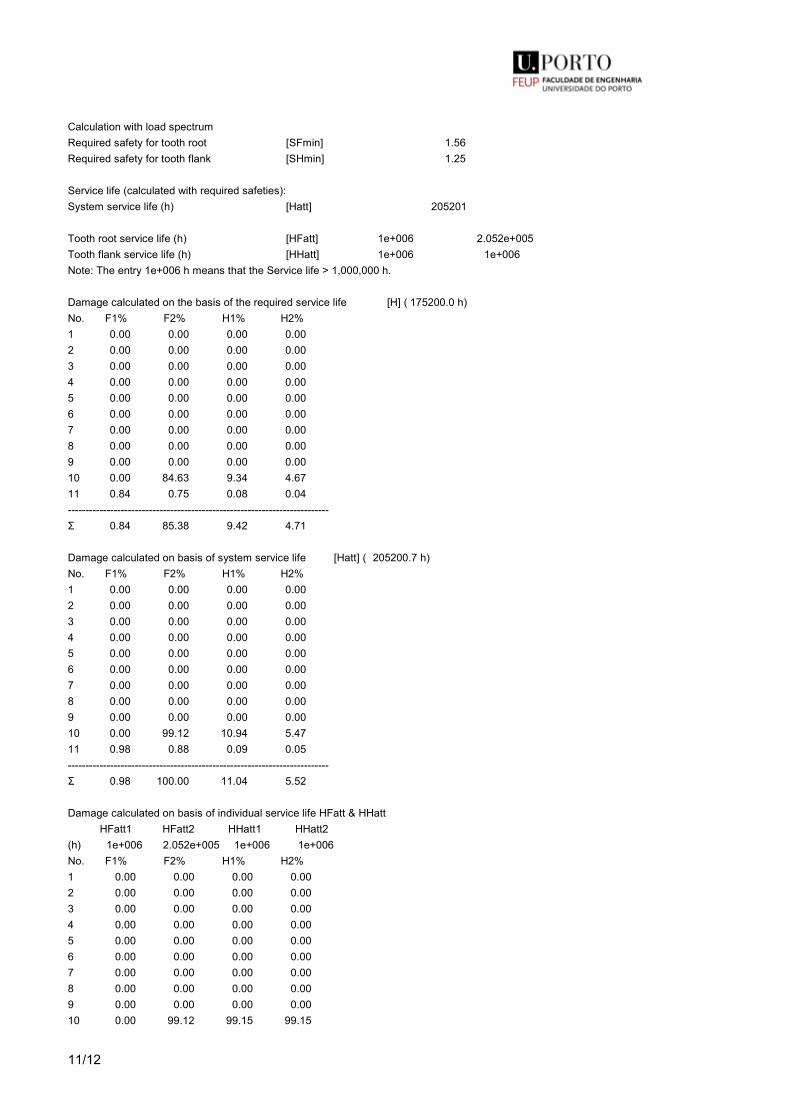
11/12
Calculation with load spectrumRequired safety for tooth root [SFmin] 1.56Required safety for tooth flank [SHmin] 1.25
Service life (calculated with required safeties):System service life (h) [Hatt] 205201
Tooth root service life (h) [HFatt] 1e+006 2.052e+005Tooth flank service life (h) [HHatt] 1e+006 1e+006Note: The entry 1e+006 h means that the Service life > 1,000,000 h.
Damage calculated on the basis of the required service life [H] ( 175200.0 h)No. F1% F2% H1% H2%1 0.00 0.00 0.00 0.002 0.00 0.00 0.00 0.003 0.00 0.00 0.00 0.004 0.00 0.00 0.00 0.005 0.00 0.00 0.00 0.006 0.00 0.00 0.00 0.007 0.00 0.00 0.00 0.008 0.00 0.00 0.00 0.009 0.00 0.00 0.00 0.0010 0.00 84.63 9.34 4.6711 0.84 0.75 0.08 0.04--------------------------------------------------------------------------Σ 0.84 85.38 9.42 4.71
Damage calculated on basis of system service life [Hatt] ( 205200.7 h)No. F1% F2% H1% H2%1 0.00 0.00 0.00 0.002 0.00 0.00 0.00 0.003 0.00 0.00 0.00 0.004 0.00 0.00 0.00 0.005 0.00 0.00 0.00 0.006 0.00 0.00 0.00 0.007 0.00 0.00 0.00 0.008 0.00 0.00 0.00 0.009 0.00 0.00 0.00 0.0010 0.00 99.12 10.94 5.4711 0.98 0.88 0.09 0.05--------------------------------------------------------------------------Σ 0.98 100.00 11.04 5.52
Damage calculated on basis of individual service life HFatt & HHatt HFatt1 HFatt2 HHatt1 HHatt2(h) 1e+006 2.052e+005 1e+006 1e+006No. F1% F2% H1% H2%1 0.00 0.00 0.00 0.002 0.00 0.00 0.00 0.003 0.00 0.00 0.00 0.004 0.00 0.00 0.00 0.005 0.00 0.00 0.00 0.006 0.00 0.00 0.00 0.007 0.00 0.00 0.00 0.008 0.00 0.00 0.00 0.009 0.00 0.00 0.00 0.0010 0.00 99.12 99.15 99.15

12/12
11 100.00 0.88 0.85 0.85--------------------------------------------------------------------Σ 100.00 100.00 100.00 100.00
Most critical duty cycle elements for Scoring (SB, Sint), Tooth Flank Fracture (SFF), hardened layer (SEHT) and Micropitting (Slam)
Calculation of the factors required to define reliability R(t) according to B. Bertsche with Weibull distribution:R(t) = 100 * Exp(-((t*fac - t0)/(T - t0))^b) %; t (h)Gear fac b t0 T R(H)%1 Tooth root 89723 1.7 1.811e+012 2.783e+012 100.001 Tooth flank 89723 1.3 1.504e+011 7.164e+011 100.002 Tooth root 44862 1.7 8.887e+009 1.366e+010 100.002 Tooth flank 44862 1.3 1.504e+011 7.164e+011 100.00
Reliability of the configuration for required service life (%) 100.00 (Bertsche)
REMARKS:- Specifications with [.e/i] imply: Maximum [e] and Minimal value [i] with consideration of all tolerances Specifications with [.m] imply: Mean value within tolerance- For the backlash tolerance, the center distance tolerances and the tooth thicknessdeviation are taken into account. Shown is the maximal and the minimal backlash corresponding the largest resp. the smallest allowances The calculation is done for the operating pitch circle.- Details of calculation method: cg according to method B End of Report lines: 638

A.2. KISSsoft Reports - Shaft calculation
A.2 KISSsoft Reports - Shaft calculation
151

A. KISSsoft Reports
152

A.2. KISSsoft Reports - Shaft calculation
A.2.1 KISSsoft Report - Planetary coaxial shafts (considering nominalload)
153

A. KISSsoft Reports
154
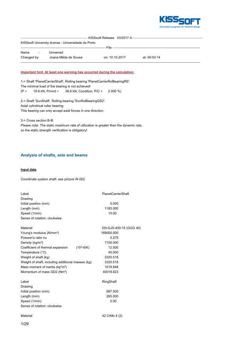
1/29
KISSsoft Release 03/2017 A KISSsoft University license - Universidade do Porto File Name : UnnamedChanged by: Joana Mêda de Sousa on: 10.10.2017 at: 00:03:14
Important hint: At least one warning has occurred during the calculation:
1-> Shaft 'PlanetCarrierShaft', Rolling bearing 'PlanetCarrierRolBearingRS':The minimal load of the bearing is not achieved!(P = 18.6 kN, Pmind = 36.6 kN, Condition: P/C > 2.000 %)
2-> Shaft 'SunShaft', Rolling bearing 'SunRolBearingGS2':Axial cylindrical roller bearing:This bearing can only accept axial forces in one direction.
3-> Cross section B-B:Please note: The static maximum rate of utilization is greater than the dynamic rate,so the static strength verification is obligatory!
Analysis of shafts, axle and beams
Input data
Coordinate system shaft: see picture W-002
Label PlanetCarrierShaftDrawingInitial position (mm) 0.000Length (mm) 1183.000Speed (1/min) 15.00Sense of rotation: clockwise
Material EN-GJS-400-15 (GGG 40)Young's modulus (N/mm²) 169000.000Poisson's ratio nu 0.275Density (kg/m³) 7100.000Coefficient of thermal expansion (10^-6/K) 12.500Temperature (°C) 40.000Weight of shaft (kg) 3320.518Weight of shaft, including additional masses (kg) 3320.518Mass moment of inertia (kg*m²) 1019.848Momentum of mass GD2 (Nm²) 40018.823
Label RingShaftDrawingInitial position (mm) 687.500Length (mm) 265.000Speed (1/min) 0.00Sense of rotation: clockwise
Material 42 CrMo 4 (2)
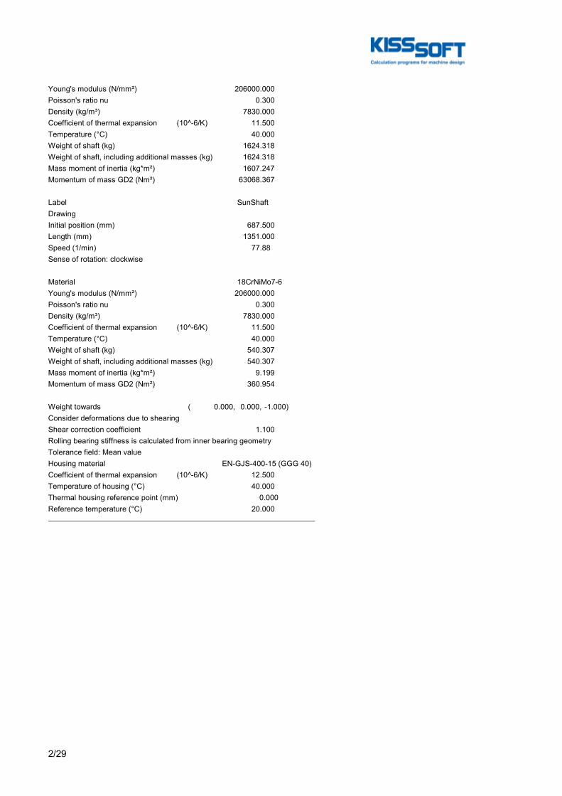
2/29
Young's modulus (N/mm²) 206000.000Poisson's ratio nu 0.300Density (kg/m³) 7830.000Coefficient of thermal expansion (10^-6/K) 11.500Temperature (°C) 40.000Weight of shaft (kg) 1624.318Weight of shaft, including additional masses (kg) 1624.318Mass moment of inertia (kg*m²) 1607.247Momentum of mass GD2 (Nm²) 63068.367
Label SunShaftDrawingInitial position (mm) 687.500Length (mm) 1351.000Speed (1/min) 77.88Sense of rotation: clockwise
Material 18CrNiMo7-6Young's modulus (N/mm²) 206000.000Poisson's ratio nu 0.300Density (kg/m³) 7830.000Coefficient of thermal expansion (10^-6/K) 11.500Temperature (°C) 40.000Weight of shaft (kg) 540.307Weight of shaft, including additional masses (kg) 540.307Mass moment of inertia (kg*m²) 9.199Momentum of mass GD2 (Nm²) 360.954
Weight towards ( 0.000, 0.000, -1.000)Consider deformations due to shearingShear correction coefficient 1.100Rolling bearing stiffness is calculated from inner bearing geometryTolerance field: Mean valueHousing material EN-GJS-400-15 (GGG 40)Coefficient of thermal expansion (10^-6/K) 12.500Temperature of housing (°C) 40.000Thermal housing reference point (mm) 0.000Reference temperature (°C) 20.000

3/29
Figure: Load applications
Shaft definition (PlanetCarrierShaft)
Outer contour
Cylinder (Cylinder) 0.000mm ... 395.000mm Diameter (mm) [d] 540.0000Length (mm) [l] 395.0000Surface roughness (µm) [Rz] 8.0000
Cylinder (Cylinder) 395.000mm ... 482.000mm Diameter (mm) [d] 558.8000Length (mm) [l] 87.0000Surface roughness (µm) [Rz] 8.0000
Cylinder (Cylinder) 482.000mm ... 580.000mm Diameter (mm) [d] 595.0000Length (mm) [l] 98.0000Surface roughness (µm) [Rz] 8.0000
Cylinder (Cylinder) 580.000mm ... 1060.000mm Diameter (mm) [d] 1500.0000Length (mm) [l] 480.0000Surface roughness (µm) [Rz] 8.0000
Cylinder (Cylinder) 1060.000mm ... 1085.000mm Diameter (mm) [d] 595.0000Length (mm) [l] 25.0000Surface roughness (µm) [Rz] 8.0000
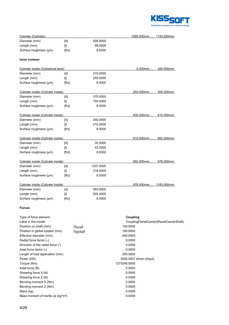
4/29
Cylinder (Cylinder) 1085.000mm ... 1183.000mm Diameter (mm) [d] 558.8000Length (mm) [l] 98.0000Surface roughness (µm) [Rz] 8.0000
Inner contour
Cylinder inside (Cylindrical bore) 0.000mm ... 250.000mm Diameter (mm) [d] 410.0000Length (mm) [l] 250.0000Surface roughness (µm) [Rz] 8.0000
Cylinder inside (Cylinder inside) 250.000mm ... 400.000mm Diameter (mm) [d] 370.0000Length (mm) [l] 150.0000Surface roughness (µm) [Rz] 8.0000
Cylinder inside (Cylinder inside) 400.000mm ... 610.000mm Diameter (mm) [d] 350.0000Length (mm) [l] 210.0000Surface roughness (µm) [Rz] 8.0000
Cylinder inside (Cylinder inside) 610.000mm ... 662.000mm Diameter (mm) [d] 30.0000Length (mm) [l] 52.0000Surface roughness (µm) [Rz] 8.0000
Cylinder inside (Cylinder inside) 662.000mm ... 978.000mm Diameter (mm) [d] 1337.0000Length (mm) [l] 316.0000Surface roughness (µm) [Rz] 8.0000
Cylinder inside (Cylinder inside) 978.000mm ... 1183.000mm Diameter (mm) [d] 483.0000Length (mm) [l] 205.0000Surface roughness (µm) [Rz] 8.0000
Forces
Type of force element CouplingLabel in the model CouplingPlanetCarrier(PlanetCarrierShaft)Position on shaft (mm) [ylocal] 100.0000Position in global system (mm) [yglobal] 100.0000Effective diameter (mm) 540.0000Radial force factor (-) 0.0000Direction of the radial force (°) 0.0000Axial force factor (-) 0.0000Length of load application (mm) 200.0000Power (kW) 2000.0007 driven (Input)Torque (Nm) 1273240.0000Axial force (N) 0.0000Shearing force X (N) 0.0000Shearing force Z (N) 0.0000Bending moment X (Nm) 0.0000Bending moment Z (Nm) 0.0000Mass (kg) 0.0000Mass moment of inertia Jp (kg*m²) 0.0000
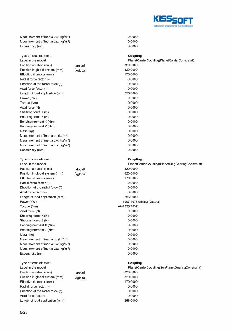
5/29
Mass moment of inertia Jxx (kg*m²) 0.0000Mass moment of inertia Jzz (kg*m²) 0.0000Eccentricity (mm) 0.0000
Type of force element CouplingLabel in the model PlanetCarrierCoupling(PlanetCarrierConstraint)Position on shaft (mm) [ylocal] 820.0000Position in global system (mm) [yglobal] 820.0000Effective diameter (mm) 170.0000Radial force factor (-) 0.0000Direction of the radial force (°) 0.0000Axial force factor (-) 0.0000Length of load application (mm) 256.0000Power (kW) 0.0000Torque (Nm) -0.0000Axial force (N) 0.0000Shearing force X (N) 0.0000Shearing force Z (N) 0.0000Bending moment X (Nm) 0.0000Bending moment Z (Nm) 0.0000Mass (kg) 0.0000Mass moment of inertia Jp (kg*m²) 0.0000Mass moment of inertia Jxx (kg*m²) 0.0000Mass moment of inertia Jzz (kg*m²) 0.0000Eccentricity (mm) 0.0000
Type of force element CouplingLabel in the model PlanetCarrierCoupling(PlanetRingGearingConstraint)Position on shaft (mm) [ylocal] 820.0000Position in global system (mm) [yglobal] 820.0000Effective diameter (mm) 170.0000Radial force factor (-) 0.0000Direction of the radial force (°) 0.0000Axial force factor (-) 0.0000Length of load application (mm) 256.0000Power (kW) 1007.4078 driving (Output)Torque (Nm) -641335.7037Axial force (N) 0.0000Shearing force X (N) 0.0000Shearing force Z (N) 0.0000Bending moment X (Nm) 0.0000Bending moment Z (Nm) 0.0000Mass (kg) 0.0000Mass moment of inertia Jp (kg*m²) 0.0000Mass moment of inertia Jxx (kg*m²) 0.0000Mass moment of inertia Jzz (kg*m²) 0.0000Eccentricity (mm) 0.0000
Type of force element CouplingLabel in the model PlanetCarrierCoupling(SunPlanetGearingConstraint)Position on shaft (mm) [ylocal] 820.0000Position in global system (mm) [yglobal] 820.0000Effective diameter (mm) 170.0000Radial force factor (-) 0.0000Direction of the radial force (°) 0.0000Axial force factor (-) 0.0000Length of load application (mm) 256.0000
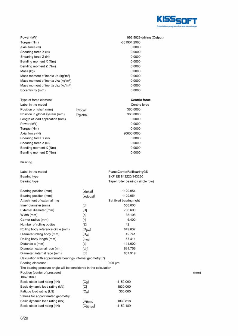
6/29
Power (kW) 992.5929 driving (Output)Torque (Nm) -631904.2963Axial force (N) 0.0000Shearing force X (N) 0.0000Shearing force Z (N) 0.0000Bending moment X (Nm) 0.0000Bending moment Z (Nm) 0.0000Mass (kg) 0.0000Mass moment of inertia Jp (kg*m²) 0.0000Mass moment of inertia Jxx (kg*m²) 0.0000Mass moment of inertia Jzz (kg*m²) 0.0000Eccentricity (mm) 0.0000
Type of force element Centric forceLabel in the model Centric forcePosition on shaft (mm) [ylocal] 360.0000Position in global system (mm) [yglobal] 360.0000Length of load application (mm) 0.0000Power (kW) 0.0000Torque (Nm) -0.0000Axial force (N) 20000.0000Shearing force X (N) 0.0000Shearing force Z (N) 0.0000Bending moment X (Nm) 0.0000Bending moment Z (Nm) 0.0000
Bearing
Label in the model PlanetCarrierRolBearingGSBearing type SKF EE 843220/843290Bearing type Taper roller bearing (single row)
Bearing position (mm) [ylokal] 1129.054Bearing position (mm) [yglobal] 1129.054Attachment of external ring Set fixed bearing rightInner diameter (mm) [d] 558.800External diameter (mm) [D] 736.600Width (mm) [b] 88.108Corner radius (mm) [r] 6.400Number of rolling bodies [Z] 42Rolling body reference circle (mm) [Dpw] 649.837Diameter rolling body (mm) [Dw] 42.741Rolling body length (mm) [Lwe] 57.411Distance a (mm) [a] 111.000Diameter, external race (mm) [do] 691.756Diameter, internal race (mm) [di] 607.919Calculation with approximate bearings internal geometry (*)Bearing clearance 0.00 µmThe bearing pressure angle will be considered in the calculationPosition (center of pressure) (mm)1062.1080Basic static load rating (kN) [C0] 4150.000Basic dynamic load rating (kN) [C] 1830.000Fatigue load rating (kN) [Cu] 305.000Values for approximated geometry:Basic dynamic load rating (kN) [Ctheo] 1830.818Basic static load rating (kN) [C0theo] 4150.189
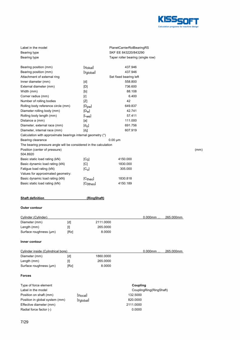
7/29
Label in the model PlanetCarrierRolBearingRSBearing type SKF EE 843220/843290Bearing type Taper roller bearing (single row)
Bearing position (mm) [ylokal] 437.946Bearing position (mm) [yglobal] 437.946Attachment of external ring Set fixed bearing leftInner diameter (mm) [d] 558.800External diameter (mm) [D] 736.600Width (mm) [b] 88.108Corner radius (mm) [r] 6.400Number of rolling bodies [Z] 42Rolling body reference circle (mm) [Dpw] 649.837Diameter rolling body (mm) [Dw] 42.741Rolling body length (mm) [Lwe] 57.411Distance a (mm) [a] 111.000Diameter, external race (mm) [do] 691.756Diameter, internal race (mm) [di] 607.919Calculation with approximate bearings internal geometry (*)Bearing clearance 0.00 µmThe bearing pressure angle will be considered in the calculationPosition (center of pressure) (mm)504.8920Basic static load rating (kN) [C0] 4150.000Basic dynamic load rating (kN) [C] 1830.000Fatigue load rating (kN) [Cu] 305.000Values for approximated geometry:Basic dynamic load rating (kN) [Ctheo] 1830.818Basic static load rating (kN) [C0theo] 4150.189
Shaft definition (RingShaft)
Outer contour
Cylinder (Cylinder) 0.000mm ... 265.000mm Diameter (mm) [d] 2111.0000Length (mm) [l] 265.0000Surface roughness (µm) [Rz] 8.0000
Inner contour
Cylinder inside (Cylindrical bore) 0.000mm ... 265.000mm Diameter (mm) [d] 1860.0000Length (mm) [l] 265.0000Surface roughness (µm) [Rz] 8.0000
Forces
Type of force element CouplingLabel in the model CouplingRing(RingShaft)Position on shaft (mm) [ylocal] 132.5000Position in global system (mm) [yglobal] 820.0000Effective diameter (mm) 2111.0000Radial force factor (-) 0.0000
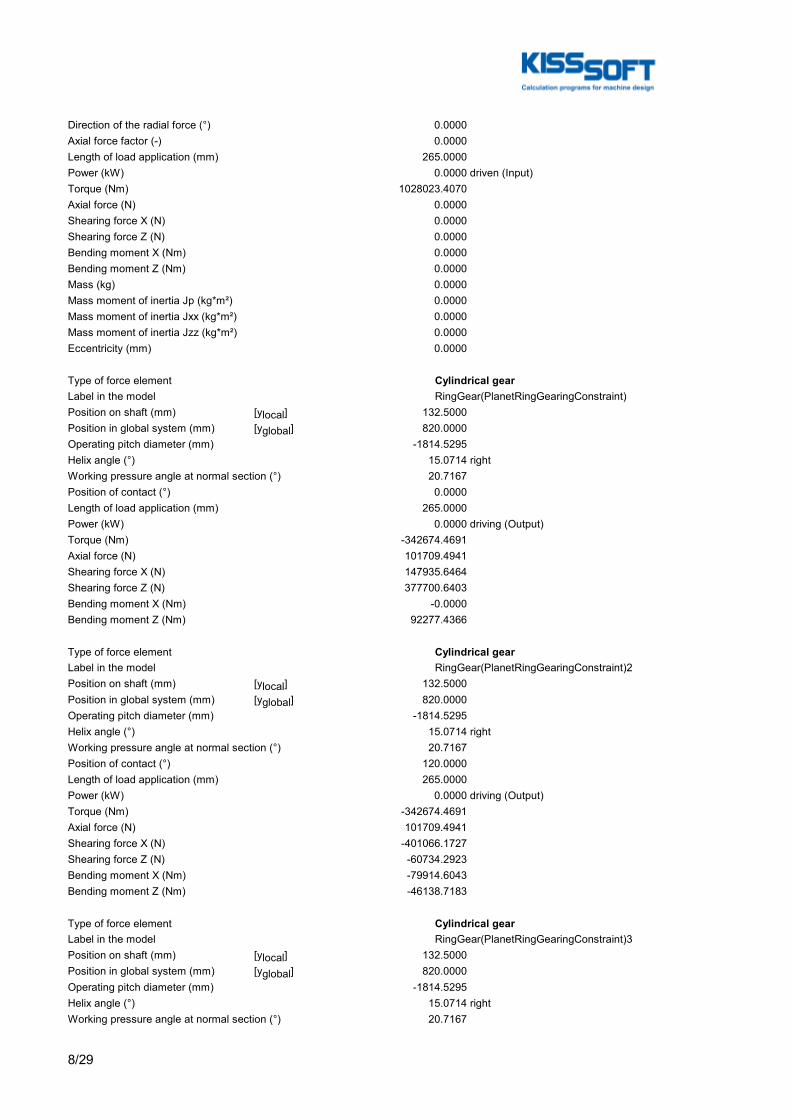
8/29
Direction of the radial force (°) 0.0000Axial force factor (-) 0.0000Length of load application (mm) 265.0000Power (kW) 0.0000 driven (Input)Torque (Nm) 1028023.4070Axial force (N) 0.0000Shearing force X (N) 0.0000Shearing force Z (N) 0.0000Bending moment X (Nm) 0.0000Bending moment Z (Nm) 0.0000Mass (kg) 0.0000Mass moment of inertia Jp (kg*m²) 0.0000Mass moment of inertia Jxx (kg*m²) 0.0000Mass moment of inertia Jzz (kg*m²) 0.0000Eccentricity (mm) 0.0000
Type of force element Cylindrical gearLabel in the model RingGear(PlanetRingGearingConstraint)Position on shaft (mm) [ylocal] 132.5000Position in global system (mm) [yglobal] 820.0000Operating pitch diameter (mm) -1814.5295Helix angle (°) 15.0714 rightWorking pressure angle at normal section (°) 20.7167Position of contact (°) 0.0000Length of load application (mm) 265.0000Power (kW) 0.0000 driving (Output)Torque (Nm) -342674.4691Axial force (N) 101709.4941Shearing force X (N) 147935.6464Shearing force Z (N) 377700.6403Bending moment X (Nm) -0.0000Bending moment Z (Nm) 92277.4366
Type of force element Cylindrical gearLabel in the model RingGear(PlanetRingGearingConstraint)2Position on shaft (mm) [ylocal] 132.5000Position in global system (mm) [yglobal] 820.0000Operating pitch diameter (mm) -1814.5295Helix angle (°) 15.0714 rightWorking pressure angle at normal section (°) 20.7167Position of contact (°) 120.0000Length of load application (mm) 265.0000Power (kW) 0.0000 driving (Output)Torque (Nm) -342674.4691Axial force (N) 101709.4941Shearing force X (N) -401066.1727Shearing force Z (N) -60734.2923Bending moment X (Nm) -79914.6043Bending moment Z (Nm) -46138.7183
Type of force element Cylindrical gearLabel in the model RingGear(PlanetRingGearingConstraint)3Position on shaft (mm) [ylocal] 132.5000Position in global system (mm) [yglobal] 820.0000Operating pitch diameter (mm) -1814.5295Helix angle (°) 15.0714 rightWorking pressure angle at normal section (°) 20.7167

9/29
Position of contact (°) 240.0000Length of load application (mm) 265.0000Power (kW) 0.0000 driving (Output)Torque (Nm) -342674.4691Axial force (N) 101709.4941Shearing force X (N) 253130.5264Shearing force Z (N) -316966.3480Bending moment X (Nm) 79914.6043Bending moment Z (Nm) -46138.7183
Bearing
Label in the model SupportBearing type Own Input
Bearing position (mm) [ylokal] 132.500Bearing position (mm) [yglobal] 820.000 Degrees of freedom X: fixedY: fixedZ: fixed Rx: fixedRy: fixedRz: fixed
Shaft definition (SunShaft)
Outer contour
Cylinder (Cylinder) 0.000mm ... 265.000mm Diameter (mm) [d] 400.0000Length (mm) [l] 265.0000Surface roughness (µm) [Rz] 8.0000
Cylinder (Cylinder) 265.000mm ... 520.000mm Diameter (mm) [d] 315.0000Length (mm) [l] 255.0000Surface roughness (µm) [Rz] 8.0000
Radius left (Radius left) r=15.00 (mm), Rz=8.0, Turned (Ra=3.2μm/125μin)
Cylinder (Cylinder) 520.000mm ... 935.000mm Diameter (mm) [d] 280.0000Length (mm) [l] 415.0000Surface roughness (µm) [Rz] 8.0000
Square groove (Square groove) b=5.00 (mm), t=4.00 (mm), r=0.50 (mm), Rz=8.0, Turned (Ra=3.2μm/125μin)
Relief groove left (Relief groove left) r=1.20 (mm), t=0.40 (mm), l=4.00 (mm), Rz=8.0, Turned (Ra=3.2μm/125μin) Form F (DIN 509), Series 1, with the usual stressing
Cylinder (Cylinder) 935.000mm ... 1105.000mm Diameter (mm) [d] 257.0000Length (mm) [l] 170.0000Surface roughness (µm) [Rz] 8.0000
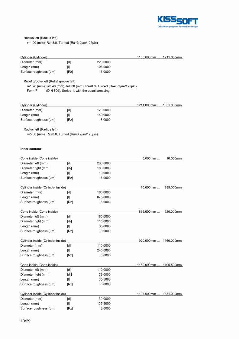
10/29
Radius left (Radius left) r=1.00 (mm), Rz=8.0, Turned (Ra=3.2μm/125μin)
Cylinder (Cylinder) 1105.000mm ... 1211.000mm Diameter (mm) [d] 220.0000Length (mm) [l] 106.0000Surface roughness (µm) [Rz] 8.0000
Relief groove left (Relief groove left) r=1.20 (mm), t=0.40 (mm), l=4.00 (mm), Rz=8.0, Turned (Ra=3.2μm/125μin) Form F (DIN 509), Series 1, with the usual stressing
Cylinder (Cylinder) 1211.000mm ... 1351.000mm Diameter (mm) [d] 170.0000Length (mm) [l] 140.0000Surface roughness (µm) [Rz] 8.0000
Radius left (Radius left) r=5.00 (mm), Rz=8.0, Turned (Ra=3.2μm/125μin)
Inner contour
Cone inside (Cone inside) 0.000mm ... 10.000mm Diameter left (mm) [dl] 200.0000Diameter right (mm) [dr] 180.0000Length (mm) [l] 10.0000Surface roughness (µm) [Rz] 8.0000
Cylinder inside (Cylinder inside) 10.000mm ... 885.000mm Diameter (mm) [d] 180.0000Length (mm) [l] 875.0000Surface roughness (µm) [Rz] 8.0000
Cone inside (Cone inside) 885.000mm ... 920.000mm Diameter left (mm) [dl] 180.0000Diameter right (mm) [dr] 110.0000Length (mm) [l] 35.0000Surface roughness (µm) [Rz] 8.0000
Cylinder inside (Cylinder inside) 920.000mm ... 1160.000mm Diameter (mm) [d] 110.0000Length (mm) [l] 240.0000Surface roughness (µm) [Rz] 8.0000
Cone inside (Cone inside) 1160.000mm ... 1195.500mm Diameter left (mm) [dl] 110.0000Diameter right (mm) [dr] 39.0000Length (mm) [l] 35.5000Surface roughness (µm) [Rz] 8.0000
Cylinder inside (Cylinder inside) 1195.500mm ... 1331.000mm Diameter (mm) [d] 39.0000Length (mm) [l] 135.5000Surface roughness (µm) [Rz] 8.0000

11/29
Forces
Type of force element Cylindrical gearLabel in the model LowSpeedGear(InfLowSpeedIntermediateGearingConstraint)Position on shaft (mm) [ylocal] 841.0000Position in global system (mm) [yglobal] 1528.5000Operating pitch diameter (mm) 1063.4483Helix angle (°) 25.0871 Double helical gearing, left-rightWorking pressure angle at normal section (°) 20.5050Position of contact (°) -150.0000Length of load application (mm) 188.0000Power (kW) 1000.0004 driving (Output)Torque (Nm) -122608.2963Axial force (N) 0.0000Shearing force X (N) 197754.6088Shearing force Z (N) -152084.4341Bending moment X (Nm) 0.0000Bending moment Z (Nm) 0.0000
Type of force element Cylindrical gearLabel in the model LowSpeedGear(SupLowSpeedIntermediateGearingConstraint)Position on shaft (mm) [ylocal] 841.0000Position in global system (mm) [yglobal] 1528.5000Operating pitch diameter (mm) 1063.4483Helix angle (°) 25.0871 Double helical gearing, left-rightWorking pressure angle at normal section (°) 20.5050Position of contact (°) 150.0000Length of load application (mm) 188.0000Power (kW) 1000.0004 driving (Output)Torque (Nm) -122608.2963Axial force (N) 0.0000Shearing force X (N) -32831.6791Shearing force Z (N) -247302.7320Bending moment X (Nm) 0.0000Bending moment Z (Nm) 0.0000
Type of force element Cylindrical gearLabel in the model SunGear(SunPlanetGearingConstraint)Position on shaft (mm) [ylocal] 132.5000Position in global system (mm) [yglobal] 820.0000Operating pitch diameter (mm) 439.2836Helix angle (°) 15.2859 leftWorking pressure angle at normal section (°) 22.7023Position of contact (°) 0.0000Length of load application (mm) 265.0000Power (kW) 666.6669 driven (Input)Torque (Nm) 81738.8642Axial force (N) 101709.4941Shearing force X (N) -161399.8748Shearing force Z (N) -372146.2206Bending moment X (Nm) -0.0000Bending moment Z (Nm) 22339.6559
Type of force element Cylindrical gearLabel in the model SunGear(SunPlanetGearingConstraint)2Position on shaft (mm) [ylocal] 132.5000Position in global system (mm) [yglobal] 820.0000

12/29
Operating pitch diameter (mm) 439.2836Helix angle (°) 15.2859 leftWorking pressure angle at normal section (°) 22.7023Position of contact (°) 120.0000Length of load application (mm) 265.0000Power (kW) 666.6669 driven (Input)Torque (Nm) 81738.8642Axial force (N) 101709.4941Shearing force X (N) 402988.0184Shearing force Z (N) 46296.7186Bending moment X (Nm) -19346.7096Bending moment Z (Nm) -11169.8280
Type of force element Cylindrical gearLabel in the model SunGear(SunPlanetGearingConstraint)3Position on shaft (mm) [ylocal] 132.5000Position in global system (mm) [yglobal] 820.0000Operating pitch diameter (mm) 439.2836Helix angle (°) 15.2859 leftWorking pressure angle at normal section (°) 22.7023Position of contact (°) 240.0000Length of load application (mm) 265.0000Power (kW) 666.6669 driven (Input)Torque (Nm) 81738.8642Axial force (N) 101709.4941Shearing force X (N) -241588.1436Shearing force Z (N) 325849.5020Bending moment X (Nm) 19346.7096Bending moment Z (Nm) -11169.8280
Bearing
Label in the model SunRolBearingGS1Bearing type SKF NCF 2244 ECJB/PEXBearing type Cylindrical roller bearing (single row) SKF ExplorerBearing position (mm) [ylokal] 1159.000Bearing position (mm) [yglobal] 1846.500Attachment of external ring Free bearingInner diameter (mm) [d] 220.000External diameter (mm) [D] 400.000Width (mm) [b] 108.000Corner radius (mm) [r] 4.000Number of rolling bodies [Z] 12Rolling body reference circle (mm) [Dpw] 299.646Diameter rolling body (mm) [Dw] 69.438Rolling body length (mm) [Lwe] 92.283Diameter, external race (mm) [do] 369.152Diameter, internal race (mm) [di] 230.140Calculation with approximate bearings internal geometry (*)Bearing clearance DIN 620:1988 C0 (135.00 µm)Basic static load rating (kN) [C0] 2600.000Basic dynamic load rating (kN) [C] 2000.000Fatigue load rating (kN) [Cu] 240.000Values for approximated geometry:Basic dynamic load rating (kN) [Ctheo] 1999.241Basic static load rating (kN) [C0theo] 2599.348

13/29
Label in the model SunRolBearingGS2Bearing type SKF 89434 MBearing type Axial cylindrical roller bearing
Bearing position (mm) [ylokal] 1328.000Bearing position (mm) [yglobal] 2015.500Attachment of external ring Axial bearingInner diameter (mm) [d] 170.000External diameter (mm) [D] 340.000Width (mm) [b] 103.000Corner radius (mm) [r] 5.000Number of rolling bodies [Z] 12Rolling body reference circle (mm) [Dpw] 258.111Diameter rolling body (mm) [Dw] 33.534Rolling body length (mm) [Lwe] 81.329Diameter, external race (mm) [do] 339.440Diameter, internal race (mm) [di] 176.782Calculation with approximate bearings internal geometry (*)Bearing clearance 0.00 µmBasic static load rating (kN) [C0] 7200.000Basic dynamic load rating (kN) [C] 1600.000Fatigue load rating (kN) [Cu] 600.000Values for approximated geometry:Basic dynamic load rating (kN) [Ctheo] 1598.920Basic static load rating (kN) [C0theo] 7200.000
Label in the model SunRolBearingRSBearing type SKF 23056 CCK/W33Bearing type Spherical roller bearings SKF ExplorerBearing position (mm) [ylokal] 573.000Bearing position (mm) [yglobal] 1260.500Attachment of external ring Free bearingInner diameter (mm) [d] 280.000External diameter (mm) [D] 420.000Width (mm) [b] 106.000Corner radius (mm) [r] 4.000Number of rolling bodies [Z] 15Rolling body reference circle (mm) [Dpw] 360.360Diameter rolling body (mm) [Dw] 47.568Rolling body length (mm) [Lwe] 52.825Diameter, external race (mm) [do] 407.580Diameter, internal race (mm) [di] 313.355Radius of curvature, external race (mm) [ro] 206.229Radius of curvature, internal race (mm) [ri] 206.229Calculation with approximate bearings internal geometry (*)Bearing clearance DIN 620:1988 C0 (215.00 µm)Basic static load rating (kN) [C0] 2850.000Basic dynamic load rating (kN) [C] 1797.000Fatigue load rating (kN) [Cu] 224.000Values for approximated geometry:Basic dynamic load rating (kN) [Ctheo] 1797.127Basic static load rating (kN) [C0theo] 2850.117

14/29
Label in the model SupportGSBearing type Own Input
Bearing position (mm) [ylokal] 1245.000Bearing position (mm) [yglobal] 1932.500 Degrees of freedom X: freeY: freeZ: free Rx: freeRy: freeRz: free
Label in the model SupportRSBearing type Own Input
Bearing position (mm) [ylokal] 132.500Bearing position (mm) [yglobal] 820.000 Degrees of freedom X: fixedY: freeZ: fixed Rx: freeRy: freeRz: free
Results
Shaft
Maximum deflection 231.185 (μm) (SunShaft pos = 1538.000 mm)
Mass center of gravityPlanetCarrierShaft (mm) 744.056RingShaft (mm) 132.500SunShaft (mm) 511.084
Total axial loadPlanetCarrierShaft (N) 20000.000RingShaft (N) 305128.482SunShaft (N) 305128.482
Torsion under torquePlanetCarrierShaft (°) -0.077RingShaft (°) 0.000SunShaft (°) -0.176
Bearing
Probability of failure [n] 10.00 %Axial clearance [uA] 10.00 µmLubricant Oil: Castrol Optigear Synthetic X 320Lubricant with additive, effect on bearing lifetime confirmed in tests.Oil lubrication, on-line filtration, ISO4406 -/17/14Lubricant - service temperature [TB] 65.00 °CLimit for factor aISO [aISOmax] 50.00Oil level [hoil] 0.00 mmOil injection lubrication

15/29
Rolling bearing service life according to ISO/TS 16281:2008
Shaft 'PlanetCarrierShaft' Rolling bearing 'PlanetCarrierRolBearingGS'Position (Y-coordinate) [y] 1129.05 mmEquivalent load [P] 46.90 kNEquivalent load [P0] 28.86 kNLife modification factor for reliability[a1] 1.000Life modification factor [aISO] 13.952Nominal bearing service life [Lnh] > 1000000 hModified bearing service life [Lnmh] > 1000000 hOperating viscosity [ν] 107.50 mm²/sMinimum EHL lubricant film thickness [hmin] 0.000 µmStatic safety factor [S0] 143.78Calculation with approximate bearings internal geometryOperating bearing clearance [Pd] 0.000 µmReference rating service life [Lnrh] > 1000000 hModified reference rating service life [Lnrmh] > 1000000 hEffective static safety factor [S0w] 50.29Static safety factor [S0ref] 115.22Equivalent load [P0ref] 36.02 kNBearing reaction force [Fx] 0.000 kNBearing reaction force [Fy] -24.294 kNBearing reaction force [Fz] 14.000 kNBearing reaction force [Fr] 14.000 kN (90°)Bearing reaction moment [Mx] -988.67 NmBearing reaction moment [My] 0.00 NmBearing reaction moment [Mz] 0.00 NmBearing reaction moment [Mr] 988.67 Nm (180°)Oil level [H] 0.000 mmLoad-independent moment of friction [M0] 13.043 NmLoad-dependent moment of friction [M1] 2.720 NmMoment of friction, cylindrical roller bearing[M2] 0.000 NmMoment of friction for seals determined according to SKF main catalog 4000/IV T DE:1994Torque of friction [Mloss] 15.763 NmPower loss [Ploss] 24.760 WThe moment of friction is calculated according to the details in SKF Catalog 1994.The factors used to calculate the torque loss have been assumed for this bearing.Displacement of bearing [ux] 0.000 µmDisplacement of bearing [uy] 334.150 µmDisplacement of bearing [uz] 0.791 µmDisplacement of bearing [ur] 0.791 µm (90°)Misalignment of bearing [rx] 0.036 mrad (0.12')Misalignment of bearing [ry] -1.346 mrad (-4.63')Misalignment of bearing [rz] -0.000 mrad (0')Misalignment of bearing [rr] 0.036 mrad (0.12')
Shaft 'PlanetCarrierShaft' Rolling bearing 'PlanetCarrierRolBearingRS'Position (Y-coordinate) [y] 437.95 mmEquivalent load [P] 18.57 kNEquivalent load [P0] 18.57 kNLife modification factor for reliability[a1] 1.000Life modification factor [aISO] 50.000Nominal bearing service life [Lnh] > 1000000 hModified bearing service life [Lnmh] > 1000000 h
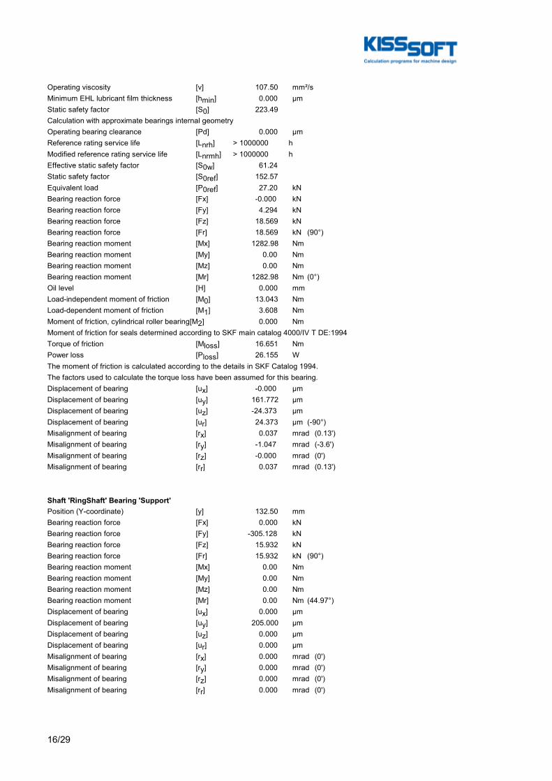
16/29
Operating viscosity [ν] 107.50 mm²/sMinimum EHL lubricant film thickness [hmin] 0.000 µmStatic safety factor [S0] 223.49Calculation with approximate bearings internal geometryOperating bearing clearance [Pd] 0.000 µmReference rating service life [Lnrh] > 1000000 hModified reference rating service life [Lnrmh] > 1000000 hEffective static safety factor [S0w] 61.24Static safety factor [S0ref] 152.57Equivalent load [P0ref] 27.20 kNBearing reaction force [Fx] -0.000 kNBearing reaction force [Fy] 4.294 kNBearing reaction force [Fz] 18.569 kNBearing reaction force [Fr] 18.569 kN (90°)Bearing reaction moment [Mx] 1282.98 NmBearing reaction moment [My] 0.00 NmBearing reaction moment [Mz] 0.00 NmBearing reaction moment [Mr] 1282.98 Nm (0°)Oil level [H] 0.000 mmLoad-independent moment of friction [M0] 13.043 NmLoad-dependent moment of friction [M1] 3.608 NmMoment of friction, cylindrical roller bearing[M2] 0.000 NmMoment of friction for seals determined according to SKF main catalog 4000/IV T DE:1994Torque of friction [Mloss] 16.651 NmPower loss [Ploss] 26.155 WThe moment of friction is calculated according to the details in SKF Catalog 1994.The factors used to calculate the torque loss have been assumed for this bearing.Displacement of bearing [ux] -0.000 µmDisplacement of bearing [uy] 161.772 µmDisplacement of bearing [uz] -24.373 µmDisplacement of bearing [ur] 24.373 µm (-90°)Misalignment of bearing [rx] 0.037 mrad (0.13')Misalignment of bearing [ry] -1.047 mrad (-3.6')Misalignment of bearing [rz] -0.000 mrad (0')Misalignment of bearing [rr] 0.037 mrad (0.13')
Shaft 'RingShaft' Bearing 'Support'Position (Y-coordinate) [y] 132.50 mmBearing reaction force [Fx] 0.000 kNBearing reaction force [Fy] -305.128 kNBearing reaction force [Fz] 15.932 kNBearing reaction force [Fr] 15.932 kN (90°)Bearing reaction moment [Mx] 0.00 NmBearing reaction moment [My] 0.00 NmBearing reaction moment [Mz] 0.00 NmBearing reaction moment [Mr] 0.00 Nm (44.97°)Displacement of bearing [ux] 0.000 µmDisplacement of bearing [uy] 205.000 µmDisplacement of bearing [uz] 0.000 µmDisplacement of bearing [ur] 0.000 µmMisalignment of bearing [rx] 0.000 mrad (0')Misalignment of bearing [ry] 0.000 mrad (0')Misalignment of bearing [rz] 0.000 mrad (0')Misalignment of bearing [rr] 0.000 mrad (0')
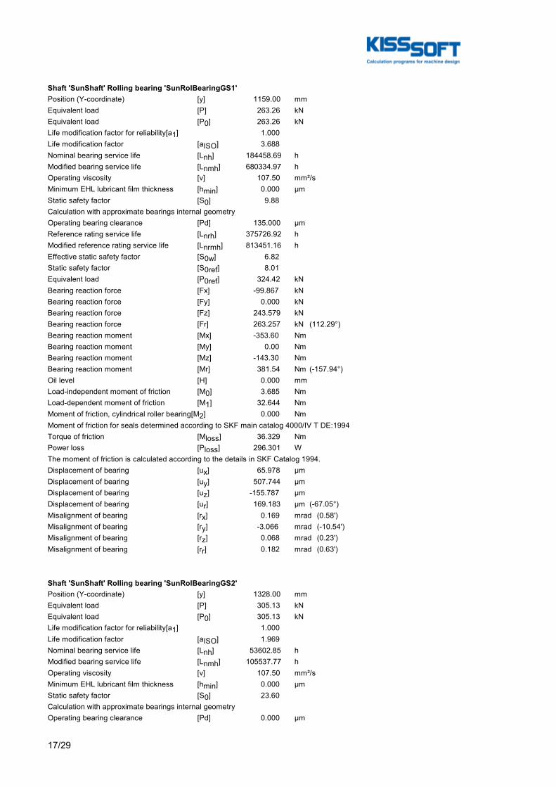
17/29
Shaft 'SunShaft' Rolling bearing 'SunRolBearingGS1'Position (Y-coordinate) [y] 1159.00 mmEquivalent load [P] 263.26 kNEquivalent load [P0] 263.26 kNLife modification factor for reliability[a1] 1.000Life modification factor [aISO] 3.688Nominal bearing service life [Lnh] 184458.69 hModified bearing service life [Lnmh] 680334.97 hOperating viscosity [ν] 107.50 mm²/sMinimum EHL lubricant film thickness [hmin] 0.000 µmStatic safety factor [S0] 9.88Calculation with approximate bearings internal geometryOperating bearing clearance [Pd] 135.000 µmReference rating service life [Lnrh] 375726.92 hModified reference rating service life [Lnrmh] 813451.16 hEffective static safety factor [S0w] 6.82Static safety factor [S0ref] 8.01Equivalent load [P0ref] 324.42 kNBearing reaction force [Fx] -99.867 kNBearing reaction force [Fy] 0.000 kNBearing reaction force [Fz] 243.579 kNBearing reaction force [Fr] 263.257 kN (112.29°)Bearing reaction moment [Mx] -353.60 NmBearing reaction moment [My] 0.00 NmBearing reaction moment [Mz] -143.30 NmBearing reaction moment [Mr] 381.54 Nm (-157.94°)Oil level [H] 0.000 mmLoad-independent moment of friction [M0] 3.685 NmLoad-dependent moment of friction [M1] 32.644 NmMoment of friction, cylindrical roller bearing[M2] 0.000 NmMoment of friction for seals determined according to SKF main catalog 4000/IV T DE:1994Torque of friction [Mloss] 36.329 NmPower loss [Ploss] 296.301 WThe moment of friction is calculated according to the details in SKF Catalog 1994.Displacement of bearing [ux] 65.978 µmDisplacement of bearing [uy] 507.744 µmDisplacement of bearing [uz] -155.787 µmDisplacement of bearing [ur] 169.183 µm (-67.05°)Misalignment of bearing [rx] 0.169 mrad (0.58')Misalignment of bearing [ry] -3.066 mrad (-10.54')Misalignment of bearing [rz] 0.068 mrad (0.23')Misalignment of bearing [rr] 0.182 mrad (0.63')
Shaft 'SunShaft' Rolling bearing 'SunRolBearingGS2'Position (Y-coordinate) [y] 1328.00 mmEquivalent load [P] 305.13 kNEquivalent load [P0] 305.13 kNLife modification factor for reliability[a1] 1.000Life modification factor [aISO] 1.969Nominal bearing service life [Lnh] 53602.85 hModified bearing service life [Lnmh] 105537.77 hOperating viscosity [ν] 107.50 mm²/sMinimum EHL lubricant film thickness [hmin] 0.000 µmStatic safety factor [S0] 23.60Calculation with approximate bearings internal geometryOperating bearing clearance [Pd] 0.000 µm

18/29
Reference rating service life [Lnrh] 157148.95 hModified reference rating service life [Lnrmh] 183103.02 hEffective static safety factor [S0w] 11.61Static safety factor [S0ref] 16.04Equivalent load [P0ref] 448.90 kNBearing reaction force [Fx] 0.000 kNBearing reaction force [Fy] -305.128 kNBearing reaction force [Fz] 0.000 kNBearing reaction force [Fr] 0.000 kNBearing reaction moment [Mx] -6783.84 NmBearing reaction moment [My] 0.00 NmBearing reaction moment [Mz] -2739.12 NmBearing reaction moment [Mr] 7315.96 Nm (-158.01°)Oil level [H] 0.000 mmLoad-independent moment of friction [M0] 2.051 NmLoad-dependent moment of friction [M1] 116.712 NmMoment of friction, cylindrical roller bearing[M2] 0.000 NmMoment of friction for seals determined according to SKF main catalog 4000/IV T DE:1994Torque of friction [Mloss] 118.763 NmPower loss [Ploss] 968.636 WThe moment of friction is calculated according to the details in SKF Catalog 1994.Displacement of bearing [ux] 57.588 µmDisplacement of bearing [uy] 536.269 µmDisplacement of bearing [uz] -135.013 µmDisplacement of bearing [ur] 146.782 µm (-66.9°)Misalignment of bearing [rx] 0.059 mrad (0.2')Misalignment of bearing [ry] -3.066 mrad (-10.54')Misalignment of bearing [rz] 0.024 mrad (0.08')Misalignment of bearing [rr] 0.064 mrad (0.22')
Shaft 'SunShaft' Rolling bearing 'SunRolBearingRS'Position (Y-coordinate) [y] 573.00 mmEquivalent load [P] 103.20 kNEquivalent load [P0] 103.20 kNLife modification factor for reliability[a1] 1.000Life modification factor [aISO] 44.334Nominal bearing service life [Lnh] > 1000000 hModified bearing service life [Lnmh] > 1000000 hOperating viscosity [ν] 107.50 mm²/sMinimum EHL lubricant film thickness [hmin] 0.000 µmStatic safety factor [S0] 27.62Calculation with approximate bearings internal geometryOperating bearing clearance [Pd] 215.000 µmReference rating service life [Lnrh] > 1000000 hModified reference rating service life [Lnrmh] > 1000000 hEffective static safety factor [S0w] 9.51Static safety factor [S0ref] 19.15Equivalent load [P0ref] 148.86 kNBearing reaction force [Fx] -39.085 kNBearing reaction force [Fy] 0.000 kNBearing reaction force [Fz] 95.511 kNBearing reaction force [Fr] 103.199 kN (112.26°)Oil level [H] 0.000 mmLoad-independent moment of friction [M0] 7.955 NmLoad-dependent moment of friction [M1] 2.702 NmMoment of friction, cylindrical roller bearing[M2] 0.000 Nm

19/29
Moment of friction for seals determined according to SKF main catalog 4000/IV T DE:1994Torque of friction [Mloss] 10.658 NmPower loss [Ploss] 86.925 WThe moment of friction is calculated according to the details in SKF Catalog 1994.Displacement of bearing [ux] 64.466 µmDisplacement of bearing [uy] 396.106 µmDisplacement of bearing [uz] -154.674 µmDisplacement of bearing [ur] 167.571 µm (-67.37°)Misalignment of bearing [rx] -0.280 mrad (-0.96')Misalignment of bearing [ry] -1.412 mrad (-4.85')Misalignment of bearing [rz] -0.117 mrad (-0.4')Misalignment of bearing [rr] 0.304 mrad (1.04')
Shaft 'SunShaft' Bearing 'SupportGS'Position (Y-coordinate) [y] 1245.00 mmBearing reaction force [Fx] 0.000 kNBearing reaction force [Fy] 0.000 kNBearing reaction force [Fz] 0.000 kNBearing reaction force [Fr] 0.000 kNDisplacement of bearing [ux] 60.686 µmDisplacement of bearing [uy] 522.896 µmDisplacement of bearing [uz] -142.681 µmDisplacement of bearing [ur] 155.051 µm (-66.96°)Misalignment of bearing [rx] 0.126 mrad (0.43')Misalignment of bearing [ry] -3.066 mrad (-10.54')Misalignment of bearing [rz] 0.051 mrad (0.17')Misalignment of bearing [rr] 0.136 mrad (0.47')
Shaft 'SunShaft' Bearing 'SupportRS'Position (Y-coordinate) [y] 132.50 mmBearing reaction force [Fx] -25.971 kNBearing reaction force [Fy] 0.000 kNBearing reaction force [Fz] 65.594 kNBearing reaction force [Fr] 70.548 kN (111.6°)Displacement of bearing [ux] 0.000 µmDisplacement of bearing [uy] 305.629 µmDisplacement of bearing [uz] 0.000 µmDisplacement of bearing [ur] 0.000 µmMisalignment of bearing [rx] -0.356 mrad (-1.23')Misalignment of bearing [ry] -0.043 mrad (-0.15')Misalignment of bearing [rz] -0.149 mrad (-0.51')Misalignment of bearing [rr] 0.386 mrad (1.33')
(*) Note about roller bearings with an approximated bearing geometry:The internal geometry of these bearings has not been input in the database.The geometry is back-calculated as specified in ISO 281, from C and C0 (details in the manufacturer's catalog).For this reason, the geometry may be different from the actual geometry.This can lead to differences in the service life calculation and, more importantly, the roller bearing stiffness.
Damage (%) [Lreq] ( 175200.000)Bin no B1 B2 B3 B4 B5 1 0.02 0.00 21.54 95.68 0.57-----------------------------------------------------------------------Σ 0.02 0.00 21.54 95.68 0.57

20/29
Utilization (%) [Lreq] ( 175200.000) B1 B2 B3 B4 B548.17 48.17 63.09 98.69 48.17Note: Utilization = (Lreq/Lh)^(1/k)Ball bearing: k = 3, roller bearing: k = 10/3
B 1: PlanetCarrierRolBearingGSB 2: PlanetCarrierRolBearingRSB 3: SunRolBearingGS1B 4: SunRolBearingGS2B 5: SunRolBearingRS
Figure: Deformation (bending etc.) (Arbitrary plane 292.6788741 121)

21/29
Nominal stresses, without taking into account stress concentrationsGEH(von Mises): sigV = ((sigB+sigZ,D)^2 + 3*(tauT+tauS)^2)^1/2SSH(Tresca): sigV = ((sigB-sigZ,D)^2 + 4*(tauT+tauS)^2)^1/2
Figure: Equivalent stress

22/29
Strength calculation as specified in the FKM Guideline (6th Edition, 2012)Summary
SunShaft
Material 18CrNiMo7-6Material type Case-carburized steelMaterial treatment case-hardenedSurface treatment No
Calculation of finite life fatigue strength and static strength
Rolled steel, case-hardening steelOverload case F1 (chapter 2.4.2): Constant mean stressSafety number according Chapter 2.5 [jF] 1.35Safety number according Chapter 1.5 [jm] 1.85Safety number according Chapter 1.5 [jp] 1.40Safety number according Chapter 1.5 [jmt] 1.40Safety number according Chapter 1.5 [jpt] 1.00
Safety number according Chapter 1.5 [jG] 1.00Cross section Pos (Y co-ord) (mm)A-A 935.00 ShoulderB-B 628.50 Square grooveC-C 622.00 Interference fitResults:Cross section Kfb KRs ALGmax SD SS SBA-A 3.43 0.89 0.42 3.19 8.40 11.86B-B 3.43 1.00 0.32 4.24 2.39 3.37C-C 2.63 1.00 0.21 6.37 2.67 3.77
Nominal safety: 1.35 1.40 1.85
Abbreviations:Kfb: Notch factor bendingKRs: Surface factorALGmax: Highest utilizationSD: Safety endurance limitSS: Safety against yield pointSB: Safety against tensile stress
Service life and damage
System service life (h) [Hatt] 1000000.00
Damage to system (%) [D] 0.00
Damage (%) [H] ( 175200.0 h)
Damage to shaft (%) [D]SunShaft: 0.000
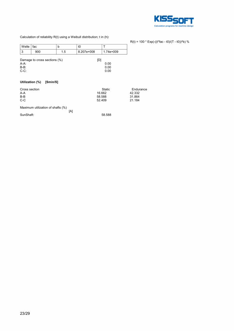
23/29
Calculation of reliability R(t) using a Weibull distribution; t in (h): R(t) = 100 * Exp(-((t*fac - t0)/(T - t0))^b) %Welle fac b t0 T3 900 1.5 8.207e+008 1.74e+009
Damage to cross sections (%) [D]A-A: 0.00B-B: 0.00C-C: 0.00
Utilization (%) [Smin/S]
Cross section Static EnduranceA-A 16.662 42.332B-B 58.588 31.864C-C 52.409 21.184
Maximum utilization of shafts (%) [A]SunShaft: 58.588
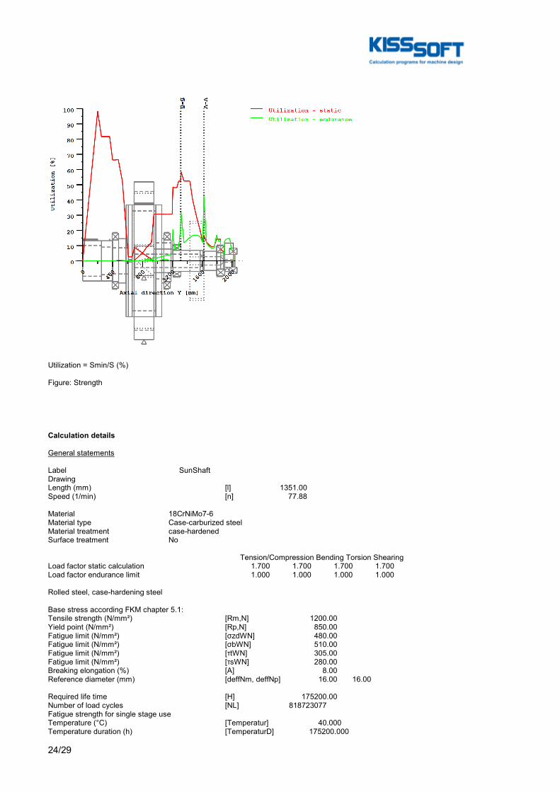
24/29
Utilization = Smin/S (%)
Figure: Strength
Calculation details
General statements
Label SunShaftDrawingLength (mm) [l] 1351.00Speed (1/min) [n] 77.88
Material 18CrNiMo7-6Material type Case-carburized steelMaterial treatment case-hardenedSurface treatment No
Tension/Compression Bending Torsion ShearingLoad factor static calculation 1.700 1.700 1.700 1.700Load factor endurance limit 1.000 1.000 1.000 1.000
Rolled steel, case-hardening steel
Base stress according FKM chapter 5.1:Tensile strength (N/mm²) [Rm,N] 1200.00Yield point (N/mm²) [Rp,N] 850.00Fatigue limit (N/mm²) [σzdWN] 480.00Fatigue limit (N/mm²) [σbWN] 510.00Fatigue limit (N/mm²) [τtWN] 305.00Fatigue limit (N/mm²) [τsWN] 280.00Breaking elongation (%) [A] 8.00Reference diameter (mm) [deffNm, deffNp] 16.00 16.00
Required life time [H] 175200.00Number of load cycles [NL] 818723077Fatigue strength for single stage useTemperature (°C) [Temperatur] 40.000Temperature duration (h) [TemperaturD] 175200.000
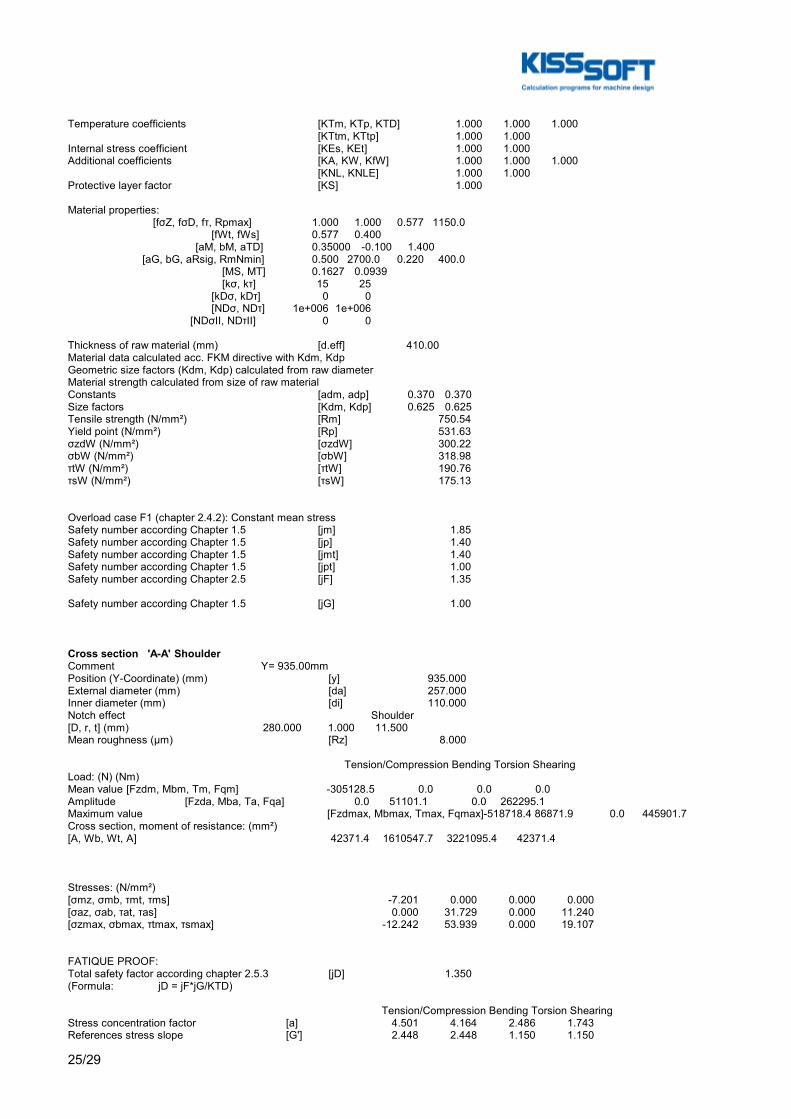
25/29
Temperature coefficients [KTm, KTp, KTD] 1.000 1.000 1.000 [KTtm, KTtp] 1.000 1.000Internal stress coefficient [KEs, KEt] 1.000 1.000Additional coefficients [KA, KW, KfW] 1.000 1.000 1.000 [KNL, KNLE] 1.000 1.000Protective layer factor [KS] 1.000
Material properties: [fσZ, fσD, fτ, Rpmax] 1.000 1.000 0.577 1150.0 [fWt, fWs] 0.577 0.400 [aM, bM, aTD] 0.35000 -0.100 1.400 [aG, bG, aRsig, RmNmin] 0.500 2700.0 0.220 400.0 [MS, MT] 0.1627 0.0939 [kσ, kτ] 15 25 [kDσ, kDτ] 0 0 [NDσ, NDτ] 1e+006 1e+006 [NDσII, NDτII] 0 0
Thickness of raw material (mm) [d.eff] 410.00Material data calculated acc. FKM directive with Kdm, KdpGeometric size factors (Kdm, Kdp) calculated from raw diameterMaterial strength calculated from size of raw materialConstants [adm, adp] 0.370 0.370Size factors [Kdm, Kdp] 0.625 0.625Tensile strength (N/mm²) [Rm] 750.54Yield point (N/mm²) [Rp] 531.63σzdW (N/mm²) [σzdW] 300.22σbW (N/mm²) [σbW] 318.98τtW (N/mm²) [τtW] 190.76τsW (N/mm²) [τsW] 175.13
Overload case F1 (chapter 2.4.2): Constant mean stressSafety number according Chapter 1.5 [jm] 1.85Safety number according Chapter 1.5 [jp] 1.40Safety number according Chapter 1.5 [jmt] 1.40Safety number according Chapter 1.5 [jpt] 1.00Safety number according Chapter 2.5 [jF] 1.35
Safety number according Chapter 1.5 [jG] 1.00
Cross section 'A-A' ShoulderComment Y= 935.00mmPosition (Y-Coordinate) (mm) [y] 935.000External diameter (mm) [da] 257.000Inner diameter (mm) [di] 110.000Notch effect Shoulder[D, r, t] (mm) 280.000 1.000 11.500Mean roughness (µm) [Rz] 8.000
Tension/Compression Bending Torsion ShearingLoad: (N) (Nm)Mean value [Fzdm, Mbm, Tm, Fqm] -305128.5 0.0 0.0 0.0Amplitude [Fzda, Mba, Ta, Fqa] 0.0 51101.1 0.0 262295.1Maximum value [Fzdmax, Mbmax, Tmax, Fqmax] -518718.4 86871.9 0.0 445901.7Cross section, moment of resistance: (mm²)[A, Wb, Wt, A] 42371.4 1610547.7 3221095.4 42371.4
Stresses: (N/mm²)[σmz, σmb, τmt, τms] -7.201 0.000 0.000 0.000[σaz, σab, τat, τas] 0.000 31.729 0.000 11.240[σzmax, σbmax, τtmax, τsmax] -12.242 53.939 0.000 19.107
FATIQUE PROOF:Total safety factor according chapter 2.5.3 [jD] 1.350(Formula: jD = jF*jG/KTD)
Tension/Compression Bending Torsion ShearingStress concentration factor [a] 4.501 4.164 2.486 1.743References stress slope [G'] 2.448 2.448 1.150 1.150

26/29
Support number [n(r)] 1.209 1.209 1.226 1.226Support number [n(d)] 1.004 1.004 1.005 1.005Mechanical material support factor [nwm] 1.062 1.062 1.062 1.062The support factor is determined with the support factor as defined by Stieler.Notch effect coefficient beta [Kf] 3.724 3.432 2.017 1.421Roughness factor [KR] 0.886 0.886 0.934 0.934Surface stabilization factor [KV] 1.200 1.200 1.200 1.200Design coefficient [KWK] 3.211 2.967 1.739 1.243Fatigue limit of part (N/mm²) [SWK] 93.494 101.185 100.693 140.857
Calculation with individual mean stress:Mean stress coefficient [KAK] 1.013 1.000 1.000 1.000Permissible amplitude (N/mm²) [SAK] 94.666 101.185 100.693 140.857Effective Miner sum [DM] 1 0.428 1 0.3Coefficient service strength [KBK] 1.000 1.000 1.000 1.000Permissible amplitude (N/mm²) [SBK] 94.666 101.185 100.693 140.857Rate of utilization [aBK] 0.000 0.423 0.000 0.108
Calculation of the combined stress types:Rate of utilization for the combined load componentsa)For outer surface (shear stress = 0) Equivalent mean stress (N/mm²) [SmV_1] 7.201 Rate of utilization [aBKv_1] 0.423b) For neutral line (Bending stress = 0) Equivalent mean stress (N/mm²) [SmV_2] 7.201 Rate of utilization [aBKv_2] 0.108
Highest utilization [aBKmax] 0.423Safety endurance limit assessment [S.Dauer] 3.189Required safety [jD] 1.350Result (%) [S/jD] 236.2
STATIC STRENGTH ASSESSMENT:Total safety factor according chapter 1.5.3 [jges] 1.400(Formula: jges = jG*Max(jm/KTm*Rp/Rm, jp/KTp, jmt/KTtm*Rp/Rm, jpt/KTtp))
Tension/Compression Bending Torsion ShearingPlastic notch factor [Kpb, Kpt] 1.270 1.268Plastic support number [npl] 1.0000 1.0570 1.2683 1.0000Strength of part (N/mm²) [SSK] 531.63 561.94 389.28 306.94Rate of utilization [aSK] 0.032 0.134 0.000 0.087
Rate of utilization for the combined load components:a)For outer surface (shear stress = 0) Equivalent stress (N/mm²) [SvBn] 41.697 Rate of utilization [aSKvBn] 0.167b) For neutral line (Bending stress = 0) Equivalent stress (N/mm²) [SvQn] 35.287 Rate of utilization [aSKvQn] 0.093
Highest utilization [aSKmax] 0.167
Safety for fracture and yield stresses:Safety against fracture [S.Rm] 11.862Required safety [jm/Ktm] 1.850Result (%) [S/jm] 641.2
Safety against yield point [S.Rp] 8.402Required safety [jp/KTp] 1.400Result (%) [S/jp] 600.2
Cross section 'B-B' Square grooveComment Y= 626.00...631.00mmPosition (Y-Coordinate) (mm) [y] 628.500External diameter (mm) [da] 280.000Inner diameter (mm) [di] 180.000Notch effect Square groove[d, r, t, m] (mm) 272.00 0.50 4.00 5.00Mean roughness (µm) [Rz] 8.000
Tension/Compression Bending Torsion ShearingLoad: (N) (Nm)

27/29
Mean value [Fzdm, Mbm, Tm, Fqm] -305128.5 0.0 245216.6 0.0Amplitude [Fzda, Mba, Ta, Fqa] 0.0 39542.5 0.0 170627.0Maximum value [Fzdmax, Mbmax, Tmax, Fqmax] -518718.4 67222.3 416868.2 290066.0Cross section, moment of resistance: (mm²)[A, Wb, Wt, A] 32660.0 1596737.7 3193475.3 32660.0
Stresses: (N/mm²)[σmz, σmb, τmt, τms] -9.343 0.000 76.787 0.000[σaz, σab, τat, τas] 0.000 24.765 0.000 10.172[σzmax, σbmax, τtmax, τsmax] -15.882 42.100 130.537 17.292
FATIQUE PROOF:Total safety factor according chapter 2.5.3 [jD] 1.350(Formula: jD = jF*jG/KTD)
Tension/Compression Bending Torsion ShearingNotch effect coefficient [β(dB)] 3.765 3.447 2.500 1.750[dB] (mm) 280.0, [rB] (mm) 0.5, [r] (mm) 0.5Support number [n(r)] 1.240 1.240 1.260 1.260Support number [n(rB)] 1.240 1.240 1.260 1.260Support number [n(d)] 1.004 1.004 1.005 1.005Mechanical material support factor [nwm] 1.062 1.062 1.062 1.062The support factor is determined with the support factor as defined by Stieler.Notch effect coefficient beta [Kf] 3.765 3.434 2.488 1.750Roughness factor [KR] 1.000 1.000 1.000 1.000Roughness factor is included into the notch effect coefficientSurface stabilization factor [KV] 1.200 1.200 1.200 1.200Design coefficient [KWK] 3.138 2.861 2.073 1.458Fatigue limit of part (N/mm²) [SWK] 95.679 104.921 84.475 120.086
Calculation with individual mean stress:Mean stress coefficient [KAK] 1.016 1.000 0.915 1.000Permissible amplitude (N/mm²) [SAK] 97.199 104.921 77.263 120.086Effective Miner sum [DM] 1 0.955 0.3 1Coefficient service strength [KBK] 1.000 1.000 1.000 1.000Permissible amplitude (N/mm²) [SBK] 97.199 104.921 77.263 120.086Rate of utilization [aBK] 0.000 0.319 0.000 0.114
Calculation of the combined stress types:Rate of utilization for the combined load componentsa)For outer surface (shear stress = 0) Equivalent mean stress (N/mm²) [SmV_1] 133.326 Rate of utilization [aBKv_1] 0.319b) For neutral line (Bending stress = 0) Equivalent mean stress (N/mm²) [SmV_2] 133.326 Rate of utilization [aBKv_2] 0.114
Highest utilization [aBKmax] 0.319Safety endurance limit assessment [S.Dauer] 4.237Required safety [jD] 1.350Result (%) [S/jD] 313.8
STATIC STRENGTH ASSESSMENT:Total safety factor according chapter 1.5.3 [jges] 1.400(Formula: jges = jG*Max(jm/KTm*Rp/Rm, jp/KTp, jmt/KTtm*Rp/Rm, jpt/KTtp))
Tension/Compression Bending Torsion ShearingPlastic notch factor [Kpb, Kpt] 1.270 1.178Plastic support number [npl] 1.0000 1.2700 1.1778 1.0000Strength of part (N/mm²) [SSK] 531.63 675.17 361.52 306.94Rate of utilization [aSK] 0.042 0.087 0.506 0.079
Rate of utilization for the combined load components:a)For outer surface (shear stress = 0) Equivalent stress (N/mm²) [SvBn] 227.612 Rate of utilization [aSKvBn] 0.522b) For neutral line (Bending stress = 0) Equivalent stress (N/mm²) [SvQn] 256.540 Rate of utilization [aSKvQn] 0.586
Highest utilization [aSKmax] 0.586
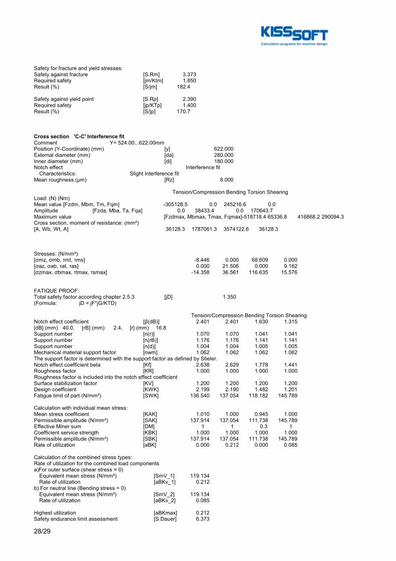
28/29
Safety for fracture and yield stresses:Safety against fracture [S.Rm] 3.373Required safety [jm/Ktm] 1.850Result (%) [S/jm] 182.4
Safety against yield point [S.Rp] 2.390Required safety [jp/KTp] 1.400Result (%) [S/jp] 170.7
Cross section 'C-C' Interference fitComment Y= 524.00...622.00mmPosition (Y-Coordinate) (mm) [y] 622.000External diameter (mm) [da] 280.000Inner diameter (mm) [di] 180.000Notch effect Interference fit Characteristics: Slight interference fitMean roughness (µm) [Rz] 8.000
Tension/Compression Bending Torsion ShearingLoad: (N) (Nm)Mean value [Fzdm, Mbm, Tm, Fqm] -305128.5 0.0 245216.6 0.0Amplitude [Fzda, Mba, Ta, Fqa] 0.0 38433.4 0.0 170643.7Maximum value [Fzdmax, Mbmax, Tmax, Fqmax] -518718.4 65336.8 416868.2 290094.3Cross section, moment of resistance: (mm²)[A, Wb, Wt, A] 36128.3 1787061.3 3574122.6 36128.3
Stresses: (N/mm²)[σmz, σmb, τmt, τms] -8.446 0.000 68.609 0.000[σaz, σab, τat, τas] 0.000 21.506 0.000 9.162[σzmax, σbmax, τtmax, τsmax] -14.358 36.561 116.635 15.576
FATIQUE PROOF:Total safety factor according chapter 2.5.3 [jD] 1.350(Formula: jD = jF*jG/KTD)
Tension/Compression Bending Torsion ShearingNotch effect coefficient [β(dB)] 2.401 2.401 1.630 1.315[dB] (mm) 40.0, [rB] (mm) 2.4, [r] (mm) 16.8Support number [n(r)] 1.070 1.070 1.041 1.041Support number [n(rB)] 1.176 1.176 1.141 1.141Support number [n(d)] 1.004 1.004 1.005 1.005Mechanical material support factor [nwm] 1.062 1.062 1.062 1.062The support factor is determined with the support factor as defined by Stieler.Notch effect coefficient beta [Kf] 2.638 2.629 1.778 1.441Roughness factor [KR] 1.000 1.000 1.000 1.000Roughness factor is included into the notch effect coefficientSurface stabilization factor [KV] 1.200 1.200 1.200 1.200Design coefficient [KWK] 2.199 2.190 1.482 1.201Fatigue limit of part (N/mm²) [SWK] 136.540 137.054 118.182 145.789
Calculation with individual mean stress:Mean stress coefficient [KAK] 1.010 1.000 0.945 1.000Permissible amplitude (N/mm²) [SAK] 137.914 137.054 111.738 145.789Effective Miner sum [DM] 1 1 0.3 1Coefficient service strength [KBK] 1.000 1.000 1.000 1.000Permissible amplitude (N/mm²) [SBK] 137.914 137.054 111.738 145.789Rate of utilization [aBK] 0.000 0.212 0.000 0.085
Calculation of the combined stress types:Rate of utilization for the combined load componentsa)For outer surface (shear stress = 0) Equivalent mean stress (N/mm²) [SmV_1] 119.134 Rate of utilization [aBKv_1] 0.212b) For neutral line (Bending stress = 0) Equivalent mean stress (N/mm²) [SmV_2] 119.134 Rate of utilization [aBKv_2] 0.085
Highest utilization [aBKmax] 0.212Safety endurance limit assessment [S.Dauer] 6.373
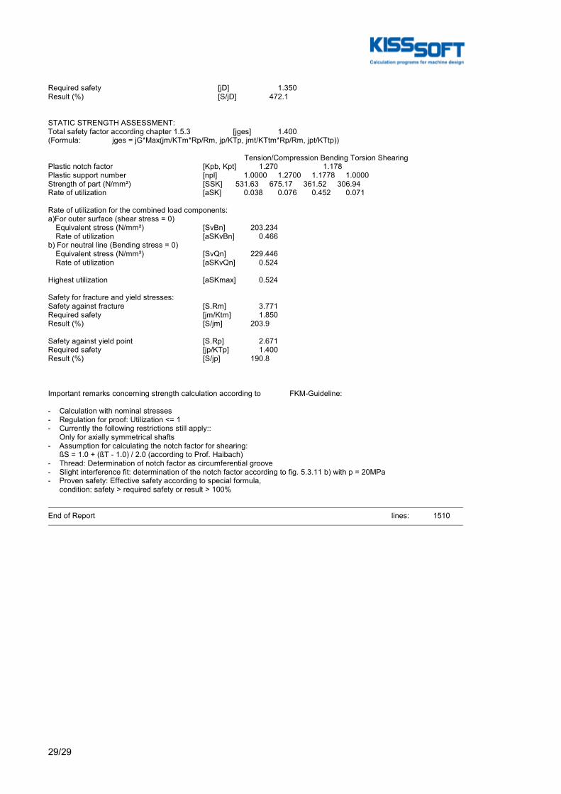
29/29
Required safety [jD] 1.350Result (%) [S/jD] 472.1
STATIC STRENGTH ASSESSMENT:Total safety factor according chapter 1.5.3 [jges] 1.400(Formula: jges = jG*Max(jm/KTm*Rp/Rm, jp/KTp, jmt/KTtm*Rp/Rm, jpt/KTtp))
Tension/Compression Bending Torsion ShearingPlastic notch factor [Kpb, Kpt] 1.270 1.178Plastic support number [npl] 1.0000 1.2700 1.1778 1.0000Strength of part (N/mm²) [SSK] 531.63 675.17 361.52 306.94Rate of utilization [aSK] 0.038 0.076 0.452 0.071
Rate of utilization for the combined load components:a)For outer surface (shear stress = 0) Equivalent stress (N/mm²) [SvBn] 203.234 Rate of utilization [aSKvBn] 0.466b) For neutral line (Bending stress = 0) Equivalent stress (N/mm²) [SvQn] 229.446 Rate of utilization [aSKvQn] 0.524
Highest utilization [aSKmax] 0.524
Safety for fracture and yield stresses:Safety against fracture [S.Rm] 3.771Required safety [jm/Ktm] 1.850Result (%) [S/jm] 203.9
Safety against yield point [S.Rp] 2.671Required safety [jp/KTp] 1.400Result (%) [S/jp] 190.8
Important remarks concerning strength calculation according to FKM-Guideline:
- Calculation with nominal stresses- Regulation for proof: Utilization <= 1- Currently the following restrictions still apply:: Only for axially symmetrical shafts- Assumption for calculating the notch factor for shearing: ßS = 1.0 + (ßT - 1.0) / 2.0 (according to Prof. Haibach)- Thread: Determination of notch factor as circumferential groove- Slight interference fit: determination of the notch factor according to fig. 5.3.11 b) with p = 20MPa- Proven safety: Effective safety according to special formula, condition: safety > required safety or result > 100%
End of Report lines: 1510

A. KISSsoft Reports
A.2.2 KISSsoft Report - Planet shaft
184

1/24
KISSsoft Release 03/2017 A KISSsoft University license - Universidade do Porto File Name : UnnamedChanged by: Joana Mêda de Sousa on: 09.10.2017 at: 23:31:40
Analysis of shafts, axle and beams
Input data
Coordinate system shaft: see picture W-002
Label PLGPNDrawingInitial position (mm) 0.000Length (mm) 463.000Speed (1/min) 15.00Sense of rotation: clockwise
Material C45 (1)Young's modulus (N/mm²) 206000.000Poisson's ratio nu 0.300Density (kg/m³) 7830.000Coefficient of thermal expansion (10^-6/K) 11.500Temperature (°C) 20.000Weight of shaft (kg) 188.244Weight of shaft, including additional masses (kg) 188.244Mass moment of inertia (kg*m²) 1.671Momentum of mass GD2 (Nm²) 65.579
Label PLGSFDrawingInitial position (mm) 88.250Length (mm) 286.000Speed (1/min) 24.88Sense of rotation: counter clockwise
Material 18CrNiMo7-6Young's modulus (N/mm²) 206000.000Poisson's ratio nu 0.300Density (kg/m³) 7830.000Coefficient of thermal expansion (10^-6/K) 11.500Temperature (°C) 20.000Weight of shaft (kg) 391.389Weight of shaft, including additional masses (kg) 391.389Mass moment of inertia (kg*m²) 30.541Momentum of mass GD2 (Nm²) 1198.444
Weight towards ( 0.000, 0.000, -1.000)Consider deformations due to shearingShear correction coefficient 1.100Rolling bearing stiffness is calculated from inner bearing geometry
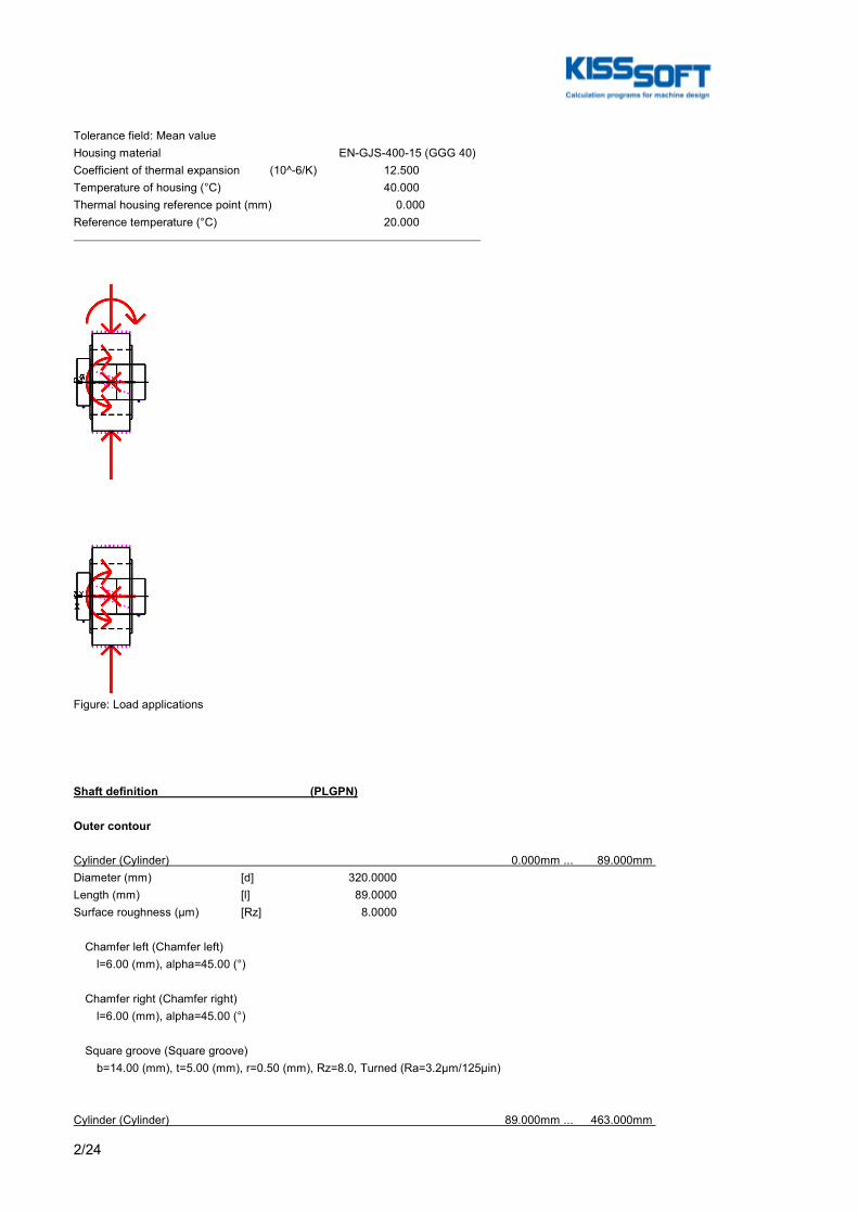
2/24
Tolerance field: Mean valueHousing material EN-GJS-400-15 (GGG 40)Coefficient of thermal expansion (10^-6/K) 12.500Temperature of housing (°C) 40.000Thermal housing reference point (mm) 0.000Reference temperature (°C) 20.000
Figure: Load applications
Shaft definition (PLGPN)
Outer contour
Cylinder (Cylinder) 0.000mm ... 89.000mm Diameter (mm) [d] 320.0000Length (mm) [l] 89.0000Surface roughness (µm) [Rz] 8.0000
Chamfer left (Chamfer left) l=6.00 (mm), alpha=45.00 (°)
Chamfer right (Chamfer right) l=6.00 (mm), alpha=45.00 (°)
Square groove (Square groove) b=14.00 (mm), t=5.00 (mm), r=0.50 (mm), Rz=8.0, Turned (Ra=3.2μm/125μin)
Cylinder (Cylinder) 89.000mm ... 463.000mm

3/24
Diameter (mm) [d] 240.0000Length (mm) [l] 374.0000Surface roughness (µm) [Rz] 8.0000
Cross hole (Cross hole) d=13.00
Inner contour
Cylinder inside (Cylindrical bore) 0.000mm ... 270.000mm Diameter (mm) [d] 13.0000Length (mm) [l] 270.0000Surface roughness (µm) [Rz] 8.0000
Forces
Type of force element CouplingLabel in the model PLGPNPCC(PCCCT)Position on shaft (mm) [ylocal] 231.2500Position in global system (mm) [yglobal] 231.2500Effective diameter (mm) 0.0000Radial force factor (-) 0.0000Direction of the radial force (°) 0.0000Axial force factor (-) 0.0000Length of load application (mm) 0.0000Power (kW) 0.0000Torque (Nm) -0.0000Axial force (load spectrum) (N) 0.0000 / 0.0000 / 0.0000Shearing force X (load spectrum) (N) 0.0000 / 0.0000 / 0.0000Shearing force Z (Load spectrum) (N) 0.0000 / 0.0000 / 0.0000Mass (kg) 0.0000Mass moment of inertia Jp (kg*m²) 0.0000Mass moment of inertia Jxx (kg*m²) 0.0000Mass moment of inertia Jzz (kg*m²) 0.0000Eccentricity (mm) 0.0000Load spectrum:
No. Frequency (%) Speed (1/min) Power (%) Torque (%) 1 1.2440e-003 15.000 -61.000 -61.000 2 1.0330e-003 15.000 -38.000 -38.000 3 1.0657e-002 15.000 -23.000 -23.000 4 9.3936e+000 15.000 0.000 0.000 5 2.7248e+001 15.000 23.000 23.000 6 1.9304e+001 15.000 45.000 45.000 7 1.3095e+001 15.000 68.000 68.000 8 2.3136e+001 15.000 98.000 98.000 9 7.7924e+000 15.000 121.000 121.000 10 1.8943e-002 15.000 144.000 144.000 11 5.5000e-005 15.000 167.000 167.000
Bearing
Label in the model SPGENBearing type Own Input
Bearing position (mm) [ylokal] 418.500
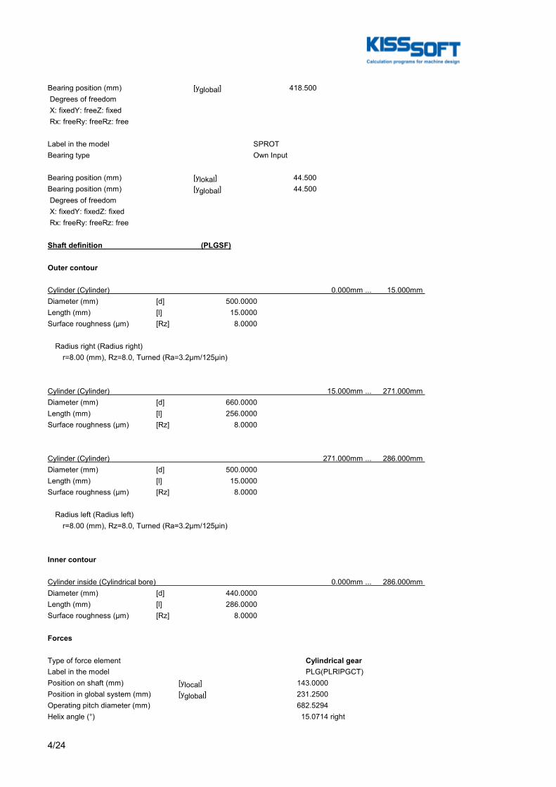
4/24
Bearing position (mm) [yglobal] 418.500 Degrees of freedom X: fixedY: freeZ: fixed Rx: freeRy: freeRz: free
Label in the model SPROTBearing type Own Input
Bearing position (mm) [ylokal] 44.500Bearing position (mm) [yglobal] 44.500 Degrees of freedom X: fixedY: fixedZ: fixed Rx: freeRy: freeRz: free
Shaft definition (PLGSF)
Outer contour
Cylinder (Cylinder) 0.000mm ... 15.000mm Diameter (mm) [d] 500.0000Length (mm) [l] 15.0000Surface roughness (µm) [Rz] 8.0000
Radius right (Radius right) r=8.00 (mm), Rz=8.0, Turned (Ra=3.2μm/125μin)
Cylinder (Cylinder) 15.000mm ... 271.000mm Diameter (mm) [d] 660.0000Length (mm) [l] 256.0000Surface roughness (µm) [Rz] 8.0000
Cylinder (Cylinder) 271.000mm ... 286.000mm Diameter (mm) [d] 500.0000Length (mm) [l] 15.0000Surface roughness (µm) [Rz] 8.0000
Radius left (Radius left) r=8.00 (mm), Rz=8.0, Turned (Ra=3.2μm/125μin)
Inner contour
Cylinder inside (Cylindrical bore) 0.000mm ... 286.000mm Diameter (mm) [d] 440.0000Length (mm) [l] 286.0000Surface roughness (µm) [Rz] 8.0000
Forces
Type of force element Cylindrical gearLabel in the model PLG(PLRIPGCT)Position on shaft (mm) [ylocal] 143.0000Position in global system (mm) [yglobal] 231.2500Operating pitch diameter (mm) 682.5294Helix angle (°) 15.0714 right

5/24
Working pressure angle at normal section (°) 20.7167Position of contact (°) -0.0000Length of load application (mm) 256.0000Power (kW) 406.3211Torque (Nm) -155964.0405Axial force (load spectrum) (N) -75071.7776 / -46766.0254 / -28305.7522Shearing force X (load spectrum) (N) -109191.3006 / -68020.8102 / -41170.4904Shearing force Z (Load spectrum) (N) -278780.8426 / -173666.7544 / -105114.0882Bending moment X (Load spectrum) (Nm) -0.0000 / -0.0000 / -0.0000Bending moment Z (Load spectrum) (Nm) -25619.3488 / -15959.5943 / -9659.7545Load spectrum, driven (input)
No. Frequency (%) Speed (1/min) Power (kW) Torque (Nm) 1 1.2440e-003 -24.878 -247.856 95138.065 2 1.0330e-003 -24.878 -154.402 59266.335 3 1.0657e-002 -24.878 -93.454 35871.729 4 9.3936e+000 -24.878 0.000 -0.000 5 2.7248e+001 -24.878 93.454 -35871.729 6 1.9304e+001 -24.878 182.845 -70183.818 7 1.3095e+001 -24.878 276.298 -106055.548 8 2.3136e+001 -24.878 398.195 -152844.760 9 7.7924e+000 -24.878 491.649 -188716.489 10 1.8943e-002 -24.878 585.102 -224588.218 11 5.5000e-005 -24.878 678.556 -260459.948
Type of force element Cylindrical gearLabel in the model PLG(SNPLPGCT)Position on shaft (mm) [ylocal] 143.0000Position in global system (mm) [yglobal] 231.2500Operating pitch diameter (mm) 692.7164Helix angle (°) 15.2859 rightWorking pressure angle at normal section (°) 22.7023Position of contact (°) 180.0000Length of load application (mm) 256.0000Power (kW) 406.3211Torque (Nm) 155964.0405Axial force (load spectrum) (N) 75071.7776 / 46766.0254 / 28305.7522Shearing force X (load spectrum) (N) 119129.2476 / 74211.6624 / 44917.5852Shearing force Z (Load spectrum) (N) -274681.1255 / -171112.8323 / -103568.2932Bending moment X (Load spectrum) (Nm) -0.0000 / -0.0000 / -0.0000Bending moment Z (Load spectrum) (Nm) -26001.7270 / -16197.7971 / -9803.9299Load spectrum, driving (output)
No. Frequency (%) Speed (1/min) Power (kW) Torque (Nm) 1 1.2440e-003 -24.878 247.856 -95138.065 2 1.0330e-003 -24.878 154.402 -59266.335 3 1.0657e-002 -24.878 93.454 -35871.729 4 9.3936e+000 -24.878 -0.000 0.000 5 2.7248e+001 -24.878 -93.454 35871.729 6 1.9304e+001 -24.878 -182.845 70183.818 7 1.3095e+001 -24.878 -276.298 106055.548 8 2.3136e+001 -24.878 -398.195 152844.760 9 7.7924e+000 -24.878 -491.649 188716.489 10 1.8943e-002 -24.878 -585.102 224588.218 11 5.5000e-005 -24.878 -678.556 260459.948
Bearing
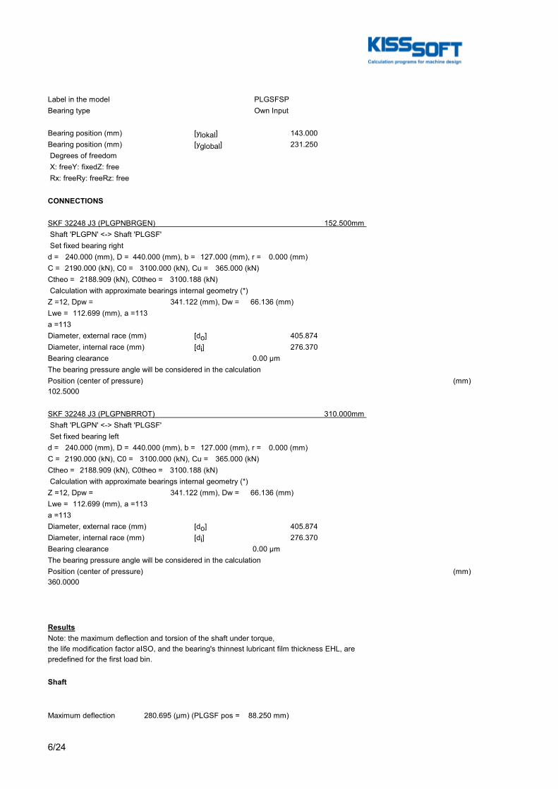
6/24
Label in the model PLGSFSPBearing type Own Input
Bearing position (mm) [ylokal] 143.000Bearing position (mm) [yglobal] 231.250 Degrees of freedom X: freeY: fixedZ: free Rx: freeRy: freeRz: free
CONNECTIONS
SKF 32248 J3 (PLGPNBRGEN) 152.500mm Shaft 'PLGPN' <-> Shaft 'PLGSF' Set fixed bearing rightd = 240.000 (mm), D = 440.000 (mm), b = 127.000 (mm), r = 0.000 (mm)C = 2190.000 (kN), C0 = 3100.000 (kN), Cu = 365.000 (kN)Ctheo = 2188.909 (kN), C0theo = 3100.188 (kN) Calculation with approximate bearings internal geometry (*)Z = 12, Dpw = 341.122 (mm), Dw = 66.136 (mm)Lwe = 112.699 (mm), a = 113a = 113Diameter, external race (mm) [do] 405.874Diameter, internal race (mm) [di] 276.370Bearing clearance 0.00 µmThe bearing pressure angle will be considered in the calculationPosition (center of pressure) (mm)102.5000
SKF 32248 J3 (PLGPNBRROT) 310.000mm Shaft 'PLGPN' <-> Shaft 'PLGSF' Set fixed bearing leftd = 240.000 (mm), D = 440.000 (mm), b = 127.000 (mm), r = 0.000 (mm)C = 2190.000 (kN), C0 = 3100.000 (kN), Cu = 365.000 (kN)Ctheo = 2188.909 (kN), C0theo = 3100.188 (kN) Calculation with approximate bearings internal geometry (*)Z = 12, Dpw = 341.122 (mm), Dw = 66.136 (mm)Lwe = 112.699 (mm), a = 113a = 113Diameter, external race (mm) [do] 405.874Diameter, internal race (mm) [di] 276.370Bearing clearance 0.00 µmThe bearing pressure angle will be considered in the calculationPosition (center of pressure) (mm)360.0000
ResultsNote: the maximum deflection and torsion of the shaft under torque,the life modification factor aISO, and the bearing's thinnest lubricant film thickness EHL, arepredefined for the first load bin.
Shaft
Maximum deflection 280.695 (μm) (PLGSF pos = 88.250 mm)
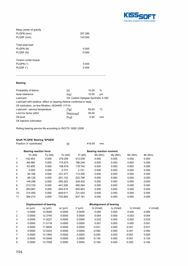
7/24
Mass center of gravityPLGPN (mm) 207.286PLGSF (mm) 143.000
Total axial loadPLGPN (N) 0.000PLGSF (N) -0.000
Torsion under torquePLGPN (°) 0.000PLGSF (°) 0.000
Bearing
Probability of failure [n] 10.00 %Axial clearance [uA] 10.00 µmLubricant Oil: Castrol Optigear Synthetic X 320Lubricant with additive, effect on bearing lifetime confirmed in tests.Oil lubrication, on-line filtration, ISO4406 -/17/14Lubricant - service temperature [TB] 65.00 °CLimit for factor aISO [aISOmax] 50.00Oil level [hoil] 0.00 mmOil injection lubrication
Rolling bearing service life according to ISO/TS 16281:2008
Shaft 'PLGPN' Bearing 'SPGEN'Position (Y-coordinate) [y] 418.50 mm
Bearing reaction force Bearing reaction moment Fx (kN) Fy (kN) Fz (kN) Fr (kN) Mx (Nm) My (Nm) Mz (Nm) Mr (Nm)1 -142.953 0.000 279.054 313.539 0.000 0.000 0.000 0.0002 -89.066 0.000 174.874 196.249 0.000 0.000 0.000 0.0003 -53.908 0.000 106.919 119.740 0.000 0.000 0.000 0.0004 0.000 0.000 2.721 2.721 0.000 0.000 0.000 0.0005 50.166 0.000 -101.477 113.200 0.000 0.000 0.000 0.0006 98.135 0.000 -201.132 223.796 0.000 0.000 0.000 0.0007 148.296 0.000 -305.323 339.432 0.000 0.000 0.000 0.0008 213.725 0.000 -441.226 490.264 0.000 0.000 0.000 0.0009 263.887 0.000 -545.419 605.903 0.000 0.000 0.000 0.00010 314.050 0.000 -649.611 721.542 0.000 0.000 0.000 0.00011 364.213 0.000 -753.804 837.181 0.000 0.000 0.000 0.000
Displacement of bearing Misalignment of bearing ux (µm) uy (µm) uz (µm) rr (µm) rx (mrad) ry (mrad) rz (mrad) rr (mrad)1 0.0000 13.0626 0.0000 0.0000 0.085 0.000 0.004 0.0852 0.0000 12.3740 0.0000 0.0000 0.054 0.000 0.003 0.0543 0.0000 11.9227 0.0000 0.0000 0.033 0.000 0.002 0.0334 0.0000 11.5118 0.0000 0.0000 0.001 0.000 0.000 0.0015 0.0000 11.8836 0.0000 0.0000 -0.031 0.000 -0.001 0.0316 0.0000 12.5224 0.0000 0.0000 -0.062 0.000 -0.001 0.0627 0.0000 13.1850 0.0000 0.0000 -0.093 0.000 -0.001 0.0938 0.0000 14.0446 0.0000 0.0000 -0.134 0.000 -0.001 0.1349 0.0000 14.7058 0.0000 0.0000 -0.166 0.000 -0.002 0.166
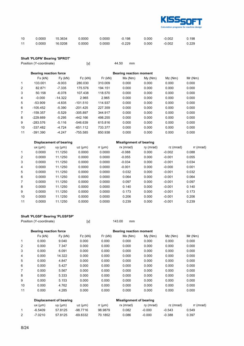
8/24
10 0.0000 15.3634 0.0000 0.0000 -0.198 0.000 -0.002 0.19811 0.0000 16.0208 0.0000 0.0000 -0.229 0.000 -0.002 0.229
Shaft 'PLGPN' Bearing 'SPROT'Position (Y-coordinate) [y] 44.50 mm
Bearing reaction force Bearing reaction moment Fx (kN) Fy (kN) Fz (kN) Fr (kN) Mx (Nm) My (Nm) Mz (Nm) Mr (Nm)1 133.001 -9.003 280.030 310.009 0.000 0.000 0.000 0.0002 82.871 -7.335 175.576 194.151 0.000 0.000 0.000 0.0003 50.158 -6.078 107.438 118.570 0.000 0.000 0.000 0.0004 -0.000 -14.322 2.965 2.965 0.000 0.000 0.000 0.0005 -53.909 -4.835 -101.510 114.937 0.000 0.000 0.000 0.0006 -105.452 -5.390 -201.425 227.359 0.000 0.000 0.000 0.0007 -159.357 -5.529 -305.897 344.917 0.000 0.000 0.000 0.0008 -229.669 -5.295 -442.166 498.255 0.000 0.000 0.000 0.0009 -283.576 -5.116 -546.639 615.816 0.000 0.000 0.000 0.00010 -337.482 -4.724 -651.112 733.377 0.000 0.000 0.000 0.00011 -391.390 -4.247 -755.585 850.938 0.000 0.000 0.000 0.000
Displacement of bearing Misalignment of bearing ux (µm) uy (µm) uz (µm) rr (µm) rx (mrad) ry (mrad) rz (mrad) rr (mrad)1 0.0000 11.1250 0.0000 0.0000 -0.088 0.000 -0.002 0.0882 0.0000 11.1250 0.0000 0.0000 -0.055 0.000 -0.001 0.0553 0.0000 11.1250 0.0000 0.0000 -0.034 0.000 -0.001 0.0344 0.0000 11.1250 0.0000 0.0000 -0.001 0.000 -0.000 0.0015 0.0000 11.1250 0.0000 0.0000 0.032 0.000 -0.001 0.0326 0.0000 11.1250 0.0000 0.0000 0.064 0.000 -0.001 0.0647 0.0000 11.1250 0.0000 0.0000 0.097 0.000 -0.001 0.0978 0.0000 11.1250 0.0000 0.0000 0.140 0.000 -0.001 0.1409 0.0000 11.1250 0.0000 0.0000 0.173 0.000 -0.001 0.17310 0.0000 11.1250 0.0000 0.0000 0.206 0.000 -0.001 0.20611 0.0000 11.1250 0.0000 0.0000 0.239 0.000 -0.001 0.239
Shaft 'PLGSF' Bearing 'PLGSFSP'Position (Y-coordinate) [y] 143.00 mm
Bearing reaction force Bearing reaction moment Fx (kN) Fy (kN) Fz (kN) Fr (kN) Mx (Nm) My (Nm) Mz (Nm) Mr (Nm)1 0.000 9.040 0.000 0.000 0.000 0.000 0.000 0.0002 0.000 7.347 0.000 0.000 0.000 0.000 0.000 0.0003 0.000 6.091 0.000 0.000 0.000 0.000 0.000 0.0004 0.000 14.322 0.000 0.000 0.000 0.000 0.000 0.0005 0.000 4.847 0.000 0.000 0.000 0.000 0.000 0.0006 0.000 5.427 0.000 0.000 0.000 0.000 0.000 0.0007 0.000 5.567 0.000 0.000 0.000 0.000 0.000 0.0008 0.000 5.333 0.000 0.000 0.000 0.000 0.000 0.0009 0.000 5.153 0.000 0.000 0.000 0.000 0.000 0.00010 0.000 4.762 0.000 0.000 0.000 0.000 0.000 0.00011 0.000 4.285 0.000 0.000 0.000 0.000 0.000 0.000
Displacement of bearing Misalignment of bearing ux (µm) uy (µm) uz (µm) rr (µm) rx (mrad) ry (mrad) rz (mrad) rr (mrad)1 -6.5409 57.8125 -98.7716 98.9879 0.082 -0.000 -0.543 0.5492 -7.0210 57.8125 -69.8332 70.1852 0.086 -0.000 -0.388 0.397

9/24
3 -7.2501 57.8125 -48.8563 49.3913 0.089 -0.000 -0.274 0.2884 0.0000 57.8125 -8.0286 8.0286 0.061 0.000 0.000 0.0615 9.0435 57.8125 47.1436 48.0032 -0.086 -0.000 0.278 0.2916 9.5697 57.8125 77.4496 78.0386 -0.081 -0.000 0.441 0.4487 9.9498 57.8125 105.7349 106.2020 -0.077 -0.000 0.590 0.5958 10.3718 57.8125 140.0938 140.4772 -0.073 -0.000 0.769 0.7739 10.5941 57.8125 165.2276 165.5669 -0.069 -0.000 0.900 0.90210 10.8254 57.8125 189.6128 189.9216 -0.066 -0.000 1.026 1.02811 11.0567 57.8125 213.5807 213.8667 -0.063 -0.000 1.149 1.151
Rolling bearing 'PLGPNBRGEN'Position (Y-coordinate) [y] 152.50 mmLife modification factor for reliability[a1] 1.000Life modification factor [aISO] 2.155Nominal bearing service life [Lnh] 93103.72 hModified bearing service life [Lnmh] 102759.19 hOperating viscosity [ν] 107.50 mm²/sMinimum EHL lubricant film thickness [hmin] 0.000 µmStatic safety factor [S0] 3.33Calculation with approximate bearings internal geometryOperating bearing clearance [Pd] 0.000 µmReference rating service life [Lnrh] 207225.86 hModified reference rating service life [Lnrmh] 198251.77 h
Bearing reaction force Bearing reaction moment Fx (kN) Fy (kN) Fz (kN) Fr (kN) Mx (Nm) My (Nm) Mz (Nm) Mr (Nm)1 -194.294 -100.320 -275.887 337.437 13006.968 0.000 -9879.057 16333.3092 -122.006 -62.281 -172.213 211.052 8114.353 0.000 -6086.448 10143.3513 -74.423 -37.599 -104.743 128.491 4926.401 0.000 -3643.358 6127.2744 0.000 -0.459 -1.732 1.732 78.678 0.000 0.000 78.6785 78.112 -37.231 100.946 127.638 -4755.267 0.000 3821.202 6100.3406 151.277 -74.076 199.886 250.678 -9438.569 0.000 7593.277 12113.8127 227.170 -112.974 303.585 379.171 -14331.226 0.000 11580.586 18425.3638 325.685 -164.089 439.214 546.790 -20686.316 0.000 16808.582 26654.3079 401.061 -203.408 543.092 675.129 -25538.305 0.000 20844.577 32965.15410 476.168 -242.844 647.250 803.535 -30400.232 0.000 24890.533 39290.11011 551.329 -282.405 751.453 932.011 -35242.569 0.000 28933.553 45598.127
Displacement of bearing Misalignment of bearing ux (µm) uy (µm) uz (µm) rr (µm) rx (mrad) ry (mrad) rz (mrad) rr (mrad)1 45.4027 -46.8034 88.9239 99.8443 -0.126 0.000 0.520 0.5352 35.1296 -46.7429 66.3717 75.0952 -0.114 0.000 0.374 0.3913 27.3163 -46.7052 49.6107 56.6340 -0.106 0.000 0.265 0.2864 -0.0000 -46.5520 12.6971 12.6971 -0.062 0.000 -0.000 0.0625 -29.2354 -46.7163 -47.9447 56.1552 0.102 0.000 -0.270 0.2896 -40.9971 -46.7850 -72.0427 82.8909 0.113 0.000 -0.425 0.4407 -51.4643 -46.8619 -93.9298 107.1045 0.125 0.000 -0.566 0.5808 -63.8670 -46.9670 -120.0352 135.9685 0.143 0.000 -0.735 0.7499 -72.7362 -47.0478 -138.8055 156.7084 0.156 0.000 -0.858 0.87210 -81.2346 -47.1308 -156.8741 176.6594 0.170 0.000 -0.975 0.99011 -89.5492 -47.2149 -174.5202 196.1539 0.184 0.000 -1.090 1.106
Rolling bearing 'PLGPNBRROT'Position (Y-coordinate) [y] 310.00 mmLife modification factor for reliability[a1] 1.000

10/24
Life modification factor [aISO] 2.063Nominal bearing service life [Lnh] 95166.07 hModified bearing service life [Lnmh] 105836.62 hOperating viscosity [ν] 107.50 mm²/sMinimum EHL lubricant film thickness [hmin] 0.000 µmStatic safety factor [S0] 3.36Calculation with approximate bearings internal geometryOperating bearing clearance [Pd] 0.000 µmReference rating service life [Lnrh] 237277.81 hModified reference rating service life [Lnrmh] 235038.89 h
Bearing reaction force Bearing reaction moment Fx (kN) Fy (kN) Fz (kN) Fr (kN) Mx (Nm) My (Nm) Mz (Nm) Mr (Nm)1 204.246 109.329 -281.360 347.678 -12578.121 0.000 -10342.529 16284.2572 128.200 69.618 -176.392 218.059 -7786.025 0.000 -6363.774 10055.8353 78.174 43.679 -107.769 133.137 -4688.822 0.000 -3800.895 6035.8814 -0.000 14.781 -2.107 2.107 -49.096 0.000 0.000 49.0965 -74.368 42.068 103.889 127.763 4524.270 0.000 3632.245 5801.9156 -143.959 79.472 204.523 250.108 9075.582 0.000 7226.328 11601.1207 -216.108 118.510 309.491 377.475 13868.165 0.000 11040.366 17726.1308 -309.739 169.391 446.039 543.037 20150.717 0.000 16063.620 25769.9689 -381.370 208.530 550.830 669.968 24930.769 0.000 19910.951 31905.94310 -452.733 247.575 655.341 796.517 29764.738 0.000 23790.828 38104.37211 -524.149 286.659 759.808 923.060 34586.249 0.000 27665.277 44289.685
Displacement of bearing Misalignment of bearing ux (µm) uy (µm) uz (µm) rr (µm) rx (mrad) ry (mrad) rz (mrad) rr (mrad)1 -30.7732 -44.5300 75.1287 81.1868 -0.046 0.000 0.522 0.5242 -20.1207 -45.2984 52.2920 56.0295 -0.063 0.000 0.375 0.3803 -12.2282 -45.8019 35.2533 37.3138 -0.075 0.000 0.266 0.2764 -0.0000 -46.2710 3.0520 3.0520 -0.061 0.000 -0.000 0.0615 11.0094 -45.8443 -34.0900 35.8237 0.073 0.000 -0.270 0.2796 21.5863 -45.1302 -58.6511 62.4974 0.055 0.000 -0.425 0.4287 31.1583 -44.3891 -80.8445 86.6411 0.038 0.000 -0.565 0.5668 42.5466 -43.4272 -107.1669 115.3037 0.017 0.000 -0.733 0.7339 50.8326 -42.6873 -126.1607 136.0165 0.000 0.000 -0.855 0.85510 58.7355 -41.9512 -144.3752 155.8655 -0.016 0.000 -0.972 0.97211 66.4540 -41.2151 -162.1694 175.2571 -0.032 0.000 -1.087 1.087
(*) Note about roller bearings with an approximated bearing geometry:The internal geometry of these bearings has not been input in the database.The geometry is back-calculated as specified in ISO 281, from C and C0 (details in the manufacturer's catalog).For this reason, the geometry may be different from the actual geometry.This can lead to differences in the service life calculation and, more importantly, the roller bearing stiffness.
Damage (%) [Lreq] ( 175200.000)Bin no B1 B2 1 0.00 0.00 2 0.00 0.00 3 0.00 0.00 4 0.00 0.00 5 0.11 0.08 6 1.27 1.01 7 5.18 4.26 8 44.50 37.36 9 37.12 31.67 10 0.19 0.16

11/24
11 0.00 0.00----------------------------Σ 88.37 74.54
Utilization (%) [Lreq] ( 175200.000) B1 B296.36 91.56Note: Utilization = (Lreq/Lh)^(1/k)Ball bearing: k = 3, roller bearing: k = 10/3
B 1: PLGPNBRGEN (Connecting rolling bearing)B 2: PLGPNBRROT (Connecting rolling bearing)
Figure: Deformation (bending etc.) (Arbitrary plane 51.67650271 121)

12/24
Nominal stresses, without taking into account stress concentrationsGEH(von Mises): sigV = ((sigB+sigZ,D)^2 + 3*(tauT+tauS)^2)^1/2SSH(Tresca): sigV = ((sigB-sigZ,D)^2 + 4*(tauT+tauS)^2)^1/2
Figure: Equivalent stress
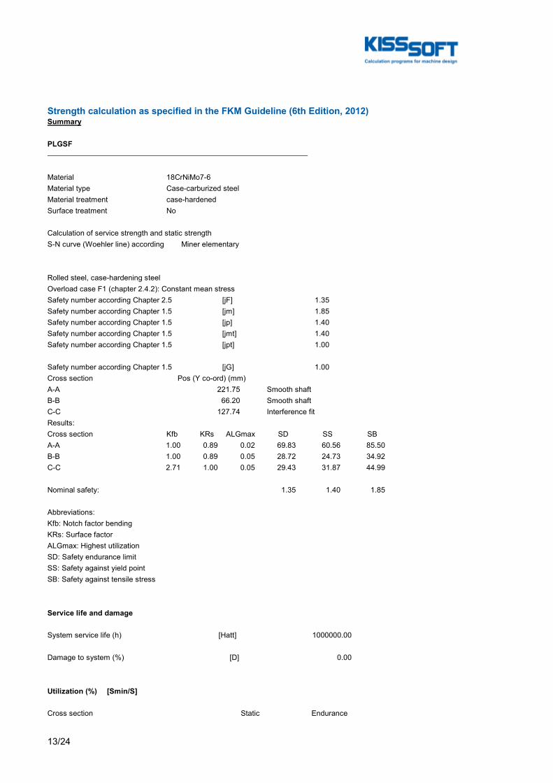
13/24
Strength calculation as specified in the FKM Guideline (6th Edition, 2012)Summary
PLGSF
Material 18CrNiMo7-6Material type Case-carburized steelMaterial treatment case-hardenedSurface treatment No
Calculation of service strength and static strengthS-N curve (Woehler line) according Miner elementary
Rolled steel, case-hardening steelOverload case F1 (chapter 2.4.2): Constant mean stressSafety number according Chapter 2.5 [jF] 1.35Safety number according Chapter 1.5 [jm] 1.85Safety number according Chapter 1.5 [jp] 1.40Safety number according Chapter 1.5 [jmt] 1.40Safety number according Chapter 1.5 [jpt] 1.00
Safety number according Chapter 1.5 [jG] 1.00Cross section Pos (Y co-ord) (mm)A-A 221.75 Smooth shaftB-B 66.20 Smooth shaftC-C 127.74 Interference fitResults:Cross section Kfb KRs ALGmax SD SS SBA-A 1.00 0.89 0.02 69.83 60.56 85.50B-B 1.00 0.89 0.05 28.72 24.73 34.92C-C 2.71 1.00 0.05 29.43 31.87 44.99
Nominal safety: 1.35 1.40 1.85
Abbreviations:Kfb: Notch factor bendingKRs: Surface factorALGmax: Highest utilizationSD: Safety endurance limitSS: Safety against yield pointSB: Safety against tensile stress
Service life and damage
System service life (h) [Hatt] 1000000.00
Damage to system (%) [D] 0.00
Utilization (%) [Smin/S]
Cross section Static Endurance

14/24
A-A 2.312 1.933B-B 5.660 4.701C-C 4.393 4.587
Maximum utilization of shafts (%) [A]PLGSF: 5.660
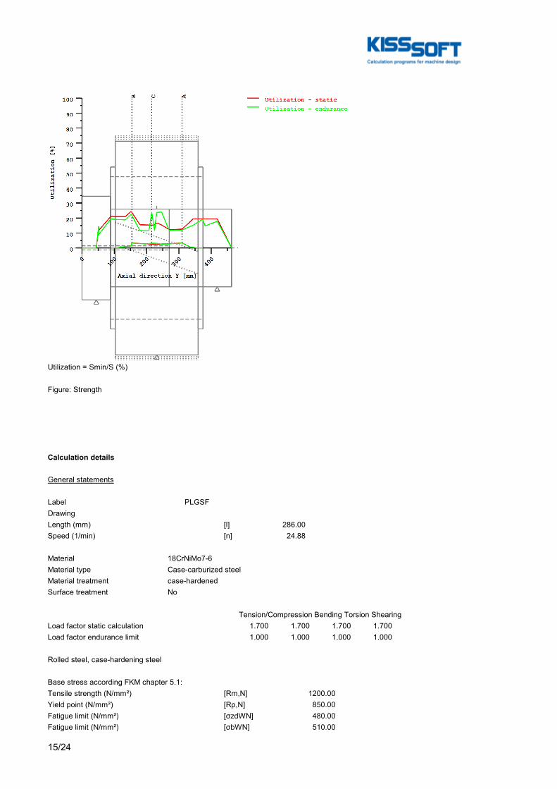
15/24
Utilization = Smin/S (%)
Figure: Strength
Calculation details
General statements
Label PLGSFDrawingLength (mm) [l] 286.00Speed (1/min) [n] 24.88
Material 18CrNiMo7-6Material type Case-carburized steelMaterial treatment case-hardenedSurface treatment No
Tension/Compression Bending Torsion ShearingLoad factor static calculation 1.700 1.700 1.700 1.700Load factor endurance limit 1.000 1.000 1.000 1.000
Rolled steel, case-hardening steel
Base stress according FKM chapter 5.1:Tensile strength (N/mm²) [Rm,N] 1200.00Yield point (N/mm²) [Rp,N] 850.00Fatigue limit (N/mm²) [σzdWN] 480.00Fatigue limit (N/mm²) [σbWN] 510.00
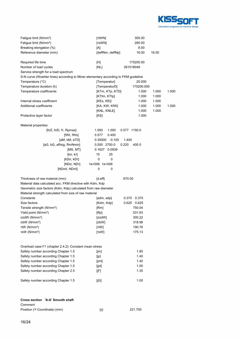
16/24
Fatigue limit (N/mm²) [τtWN] 305.00Fatigue limit (N/mm²) [τsWN] 280.00Breaking elongation (%) [A] 8.00Reference diameter (mm) [deffNm, deffNp] 16.00 16.00
Required life time [H] 175200.00Number of load cycles [NL] 261518049Service strength for a load spectrumS-N curve (Woehler lines) according to Miner elementary according to FKM guidelineTemperature (°C) [Temperatur] 20.000Temperature duration (h) [TemperaturD] 175200.000Temperature coefficients [KTm, KTp, KTD] 1.000 1.000 1.000 [KTtm, KTtp] 1.000 1.000Internal stress coefficient [KEs, KEt] 1.000 1.000Additional coefficients [KA, KW, KfW] 1.000 1.000 1.000 [KNL, KNLE] 1.000 1.000Protective layer factor [KS] 1.000
Material properties: [fσZ, fσD, fτ, Rpmax] 1.000 1.000 0.577 1150.0 [fWt, fWs] 0.577 0.400 [aM, bM, aTD] 0.35000 -0.100 1.400 [aG, bG, aRsig, RmNmin] 0.500 2700.0 0.220 400.0 [MS, MT] 0.1627 0.0939 [kσ, kτ] 15 25 [kDσ, kDτ] 0 0 [NDσ, NDτ] 1e+006 1e+006 [NDσII, NDτII] 0 0
Thickness of raw material (mm) [d.eff] 670.00Material data calculated acc. FKM directive with Kdm, KdpGeometric size factors (Kdm, Kdp) calculated from raw diameterMaterial strength calculated from size of raw materialConstants [adm, adp] 0.370 0.370Size factors [Kdm, Kdp] 0.625 0.625Tensile strength (N/mm²) [Rm] 750.54Yield point (N/mm²) [Rp] 531.63σzdW (N/mm²) [σzdW] 300.22σbW (N/mm²) [σbW] 318.98τtW (N/mm²) [τtW] 190.76τsW (N/mm²) [τsW] 175.13
Overload case F1 (chapter 2.4.2): Constant mean stressSafety number according Chapter 1.5 [jm] 1.85Safety number according Chapter 1.5 [jp] 1.40Safety number according Chapter 1.5 [jmt] 1.40Safety number according Chapter 1.5 [jpt] 1.00Safety number according Chapter 2.5 [jF] 1.35
Safety number according Chapter 1.5 [jG] 1.00
Cross section 'A-A' Smooth shaftCommentPosition (Y-Coordinate) (mm) [y] 221.750

17/24
External diameter (mm) [da] 660.000Inner diameter (mm) [di] 440.000Notch effect Smooth shaftMean roughness (µm) [Rz] 8.000
Tension/Compression Bending Torsion ShearingLoad: (N) (Nm)Mean value [Fzdm, Mbm, Tm, Fqm] -0.0 0.0 0.0 0.0Amplitude [Fzda, Mba, Ta, Fqa] 0.0 27989.9 0.0 290778.6Maximum value [Fzdmax, Mbmax, Tmax, Fqmax] -0.0 47582.9 0.0 494323.6Cross section, moment of resistance: (mm²)[A, Wb, Wt, A] 190066.4 22649574.0 45299148.1 190066.4
Load spectrum, load base values (Mean-value + Amplitude):No. Frequency (%) Tens./Compres. (N) Bending (Nm) Torsion (Nm) Shearing (N) 1 1.2440e-003 0.000 10322.088 0.000 107263.552 2 1.0330e-003 0.000 6432.146 0.000 67110.178 3 1.0657e-002 0.000 3895.240 0.000 40923.195 4 9.3936e+000 -0.000 20.599 0.000 769.942 5 2.7248e+001 -0.000 3850.396 0.000 39383.560 6 1.9304e+001 -0.000 7538.362 0.000 77791.135 7 1.3095e+001 -0.000 11393.980 0.000 117944.509 8 2.3136e+001 -0.000 16423.052 0.000 170318.476 9 7.7924e+000 -0.000 20278.677 0.000 210471.851 10 1.8943e-002 -0.000 24134.302 0.000 250625.226 11 5.5000e-005 -0.000 27989.927 0.000 290778.601
Stresses: (N/mm²)[σmz, σmb, τmt, τms] -0.000 0.000 0.000 0.000[σaz, σab, τat, τas] 0.000 1.236 0.000 2.981[σzmax, σbmax, τtmax, τsmax] -0.000 2.101 0.000 5.068
FATIQUE PROOF:Total safety factor according chapter 2.5.3 [jD] 1.350(Formula: jD = jF*jG/KTD)
Tension/Compression Bending Torsion ShearingStress concentration factor [a] 1.000 1.000 1.000 1.000References stress slope [G'] 0.000 0.000 0.000 0.000Support number [n(r)] 1.000 1.000 1.000 1.000Support number [n(d)] 1.002 1.002 1.002 1.002Mechanical material support factor [nwm] 1.062 1.062 1.062 1.062The support factor is determined with the support factor as defined by Stieler.Notch effect coefficient beta [Kf] 1.000 0.998 0.998 1.000Roughness factor [KR] 0.886 0.886 0.934 0.934Surface stabilization factor [KV] 1.000 1.100 1.100 1.100Design coefficient [KWK] 1.129 1.025 0.971 0.973Fatigue limit of part (N/mm²) [SWK] 265.958 292.968 180.299 179.947
Calculation with individual mean stress:Mean stress coefficient [KAK] 1.000 1.000 1.000 1.000Permissible amplitude (N/mm²) [SAK] 265.958 292.968 180.299 179.947Effective Miner sum [DM] 1 0.328 0.3 0.3
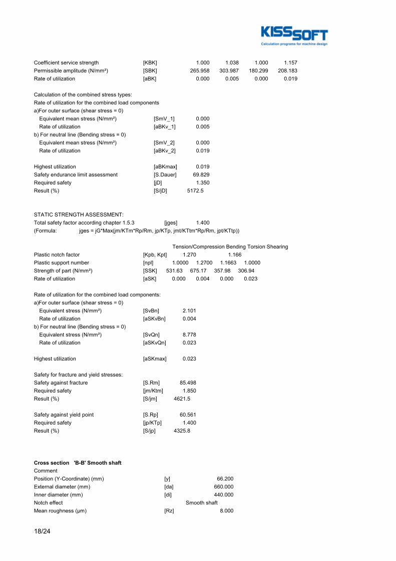
18/24
Coefficient service strength [KBK] 1.000 1.038 1.000 1.157Permissible amplitude (N/mm²) [SBK] 265.958 303.987 180.299 208.183Rate of utilization [aBK] 0.000 0.005 0.000 0.019
Calculation of the combined stress types:Rate of utilization for the combined load componentsa)For outer surface (shear stress = 0) Equivalent mean stress (N/mm²) [SmV_1] 0.000 Rate of utilization [aBKv_1] 0.005b) For neutral line (Bending stress = 0) Equivalent mean stress (N/mm²) [SmV_2] 0.000 Rate of utilization [aBKv_2] 0.019
Highest utilization [aBKmax] 0.019Safety endurance limit assessment [S.Dauer] 69.829Required safety [jD] 1.350Result (%) [S/jD] 5172.5
STATIC STRENGTH ASSESSMENT:Total safety factor according chapter 1.5.3 [jges] 1.400(Formula: jges = jG*Max(jm/KTm*Rp/Rm, jp/KTp, jmt/KTtm*Rp/Rm, jpt/KTtp))
Tension/Compression Bending Torsion ShearingPlastic notch factor [Kpb, Kpt] 1.270 1.166Plastic support number [npl] 1.0000 1.2700 1.1663 1.0000Strength of part (N/mm²) [SSK] 531.63 675.17 357.98 306.94Rate of utilization [aSK] 0.000 0.004 0.000 0.023
Rate of utilization for the combined load components:a)For outer surface (shear stress = 0) Equivalent stress (N/mm²) [SvBn] 2.101 Rate of utilization [aSKvBn] 0.004b) For neutral line (Bending stress = 0) Equivalent stress (N/mm²) [SvQn] 8.778 Rate of utilization [aSKvQn] 0.023
Highest utilization [aSKmax] 0.023
Safety for fracture and yield stresses:Safety against fracture [S.Rm] 85.498Required safety [jm/Ktm] 1.850Result (%) [S/jm] 4621.5
Safety against yield point [S.Rp] 60.561Required safety [jp/KTp] 1.400Result (%) [S/jp] 4325.8
Cross section 'B-B' Smooth shaftCommentPosition (Y-Coordinate) (mm) [y] 66.200External diameter (mm) [da] 660.000Inner diameter (mm) [di] 440.000Notch effect Smooth shaftMean roughness (µm) [Rz] 8.000
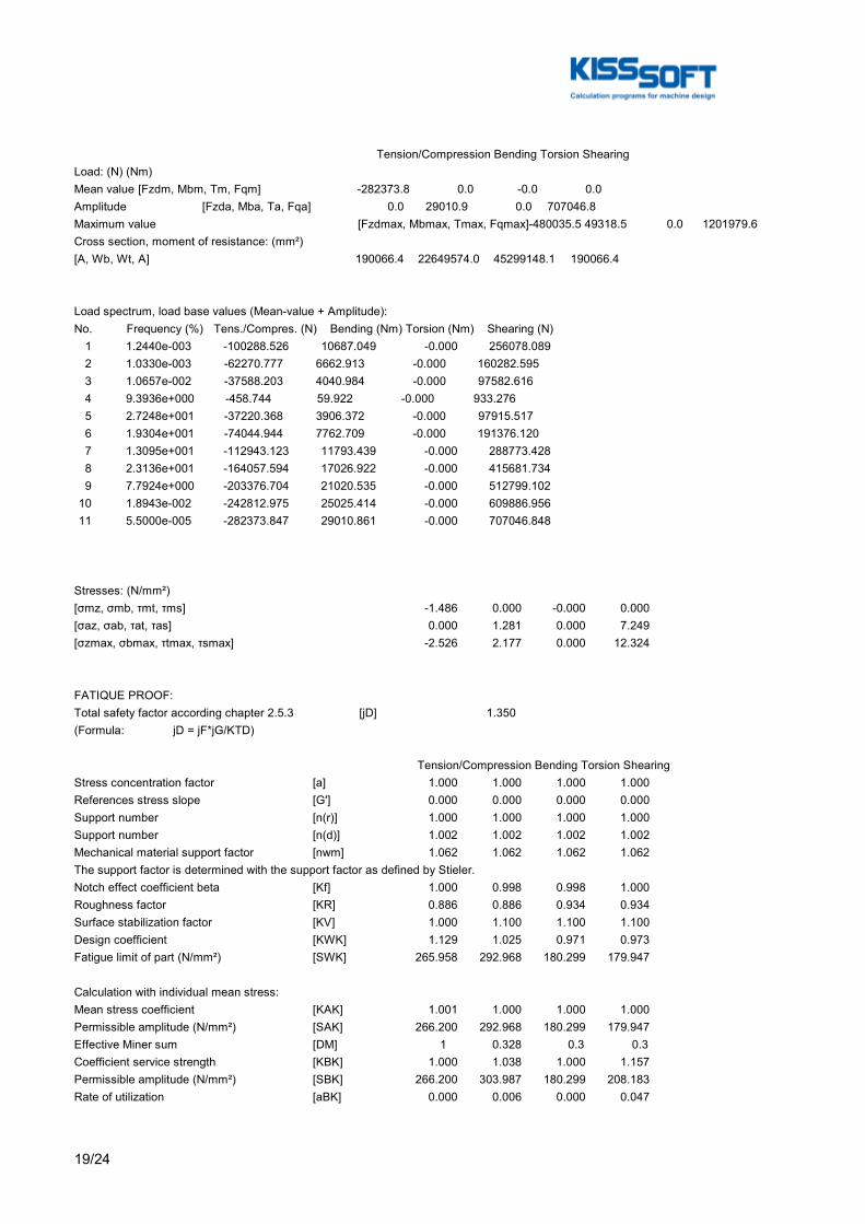
19/24
Tension/Compression Bending Torsion ShearingLoad: (N) (Nm)Mean value [Fzdm, Mbm, Tm, Fqm] -282373.8 0.0 -0.0 0.0Amplitude [Fzda, Mba, Ta, Fqa] 0.0 29010.9 0.0 707046.8Maximum value [Fzdmax, Mbmax, Tmax, Fqmax] -480035.5 49318.5 0.0 1201979.6Cross section, moment of resistance: (mm²)[A, Wb, Wt, A] 190066.4 22649574.0 45299148.1 190066.4
Load spectrum, load base values (Mean-value + Amplitude):No. Frequency (%) Tens./Compres. (N) Bending (Nm) Torsion (Nm) Shearing (N) 1 1.2440e-003 -100288.526 10687.049 -0.000 256078.089 2 1.0330e-003 -62270.777 6662.913 -0.000 160282.595 3 1.0657e-002 -37588.203 4040.984 -0.000 97582.616 4 9.3936e+000 -458.744 59.922 -0.000 933.276 5 2.7248e+001 -37220.368 3906.372 -0.000 97915.517 6 1.9304e+001 -74044.944 7762.709 -0.000 191376.120 7 1.3095e+001 -112943.123 11793.439 -0.000 288773.428 8 2.3136e+001 -164057.594 17026.922 -0.000 415681.734 9 7.7924e+000 -203376.704 21020.535 -0.000 512799.102 10 1.8943e-002 -242812.975 25025.414 -0.000 609886.956 11 5.5000e-005 -282373.847 29010.861 -0.000 707046.848
Stresses: (N/mm²)[σmz, σmb, τmt, τms] -1.486 0.000 -0.000 0.000[σaz, σab, τat, τas] 0.000 1.281 0.000 7.249[σzmax, σbmax, τtmax, τsmax] -2.526 2.177 0.000 12.324
FATIQUE PROOF:Total safety factor according chapter 2.5.3 [jD] 1.350(Formula: jD = jF*jG/KTD)
Tension/Compression Bending Torsion ShearingStress concentration factor [a] 1.000 1.000 1.000 1.000References stress slope [G'] 0.000 0.000 0.000 0.000Support number [n(r)] 1.000 1.000 1.000 1.000Support number [n(d)] 1.002 1.002 1.002 1.002Mechanical material support factor [nwm] 1.062 1.062 1.062 1.062The support factor is determined with the support factor as defined by Stieler.Notch effect coefficient beta [Kf] 1.000 0.998 0.998 1.000Roughness factor [KR] 0.886 0.886 0.934 0.934Surface stabilization factor [KV] 1.000 1.100 1.100 1.100Design coefficient [KWK] 1.129 1.025 0.971 0.973Fatigue limit of part (N/mm²) [SWK] 265.958 292.968 180.299 179.947
Calculation with individual mean stress:Mean stress coefficient [KAK] 1.001 1.000 1.000 1.000Permissible amplitude (N/mm²) [SAK] 266.200 292.968 180.299 179.947Effective Miner sum [DM] 1 0.328 0.3 0.3Coefficient service strength [KBK] 1.000 1.038 1.000 1.157Permissible amplitude (N/mm²) [SBK] 266.200 303.987 180.299 208.183Rate of utilization [aBK] 0.000 0.006 0.000 0.047

20/24
Calculation of the combined stress types:Rate of utilization for the combined load componentsa)For outer surface (shear stress = 0) Equivalent mean stress (N/mm²) [SmV_1] 1.486 Rate of utilization [aBKv_1] 0.006b) For neutral line (Bending stress = 0) Equivalent mean stress (N/mm²) [SmV_2] 1.486 Rate of utilization [aBKv_2] 0.047
Highest utilization [aBKmax] 0.047Safety endurance limit assessment [S.Dauer] 28.718Required safety [jD] 1.350Result (%) [S/jD] 2127.3
STATIC STRENGTH ASSESSMENT:Total safety factor according chapter 1.5.3 [jges] 1.400(Formula: jges = jG*Max(jm/KTm*Rp/Rm, jp/KTp, jmt/KTtm*Rp/Rm, jpt/KTtp))
Tension/Compression Bending Torsion ShearingPlastic notch factor [Kpb, Kpt] 1.270 1.166Plastic support number [npl] 1.0000 1.2700 1.1663 1.0000Strength of part (N/mm²) [SSK] 531.63 675.17 357.98 306.94Rate of utilization [aSK] 0.007 0.005 0.000 0.056
Rate of utilization for the combined load components:a)For outer surface (shear stress = 0) Equivalent stress (N/mm²) [SvBn] 0.348 Rate of utilization [aSKvBn] 0.011b) For neutral line (Bending stress = 0) Equivalent stress (N/mm²) [SvQn] 21.494 Rate of utilization [aSKvQn] 0.057
Highest utilization [aSKmax] 0.057
Safety for fracture and yield stresses:Safety against fracture [S.Rm] 34.918Required safety [jm/Ktm] 1.850Result (%) [S/jm] 1887.5
Safety against yield point [S.Rp] 24.734Required safety [jp/KTp] 1.400Result (%) [S/jp] 1766.7
Cross section 'C-C' Interference fitComment Y= 0.75...127.75mmPosition (Y-Coordinate) (mm) [y] 127.740External diameter (mm) [da] 660.000Inner diameter (mm) [di] 440.000Notch effect Interference fit Characteristics: Slight interference fitMean roughness (µm) [Rz] 8.000
Tension/Compression Bending Torsion ShearingLoad: (N) (Nm)
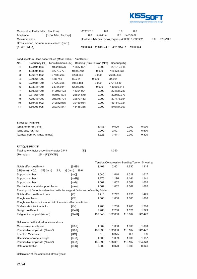
21/24
Mean value [Fzdm, Mbm, Tm, Fqm] -282373.8 0.0 0.0 0.0Amplitude [Fzda, Mba, Ta, Fqa] 0.0 45448.4 0.0 546184.3Maximum value [Fzdmax, Mbmax, Tmax, Fqmax] -480035.5 77262.2 0.0 928513.3Cross section, moment of resistance: (mm²)[A, Wb, Wt, A] 190066.4 22649574.0 45299148.1 190066.4
Load spectrum, load base values (Mean-value + Amplitude):No. Frequency (%) Tens./Compres. (N) Bending (Nm) Torsion (Nm) Shearing (N) 1 1.2440e-003 -100288.526 16687.821 0.000 201012.918 2 1.0330e-003 -62270.777 10392.164 0.000 126128.633 3 1.0657e-002 -37588.203 6298.665 0.000 76889.856 4 9.3936e+000 -458.744 89.714 0.000 34.964 5 2.7248e+001 -37220.368 6084.484 0.000 77216.810 6 1.9304e+001 -74044.944 12096.699 0.000 149660.513 7 1.3095e+001 -112943.123 18394.021 0.000 224837.283 8 2.3136e+001 -164057.594 26604.670 0.000 322480.373 9 7.7924e+000 -203376.704 32873.113 0.000 397175.954 10 1.8943e-002 -242812.975 39169.084 0.000 471649.721 11 5.5000e-005 -282373.847 45448.366 0.000 546184.307
Stresses: (N/mm²)[σmz, σmb, τmt, τms] -1.486 0.000 0.000 0.000[σaz, σab, τat, τas] 0.000 2.007 0.000 5.600[σzmax, σbmax, τtmax, τsmax] -2.526 3.411 0.000 9.520
FATIQUE PROOF:Total safety factor according chapter 2.5.3 [jD] 1.350(Formula: jD = jF*jG/KTD)
Tension/Compression Bending Torsion ShearingNotch effect coefficient [β(dB)] 2.401 2.401 1.630 1.315[dB] (mm) 40.0, [rB] (mm) 2.4, [r] (mm) 39.6Support number [n(r)] 1.040 1.040 1.017 1.017Support number [n(rB)] 1.176 1.176 1.141 1.141Support number [n(d)] 1.002 1.002 1.002 1.002Mechanical material support factor [nwm] 1.062 1.062 1.062 1.062The support factor is determined with the support factor as defined by Stieler.Notch effect coefficient beta [Kf] 2.716 2.712 1.825 1.475Roughness factor [KR] 1.000 1.000 1.000 1.000Roughness factor is included into the notch effect coefficientSurface stabilization factor [KV] 1.200 1.200 1.200 1.200Design coefficient [KWK] 2.263 2.260 1.521 1.229Fatigue limit of part (N/mm²) [SWK] 132.648 132.860 115.167 142.472
Calculation with individual mean stress:Mean stress coefficient [KAK] 1.002 1.000 1.000 1.000Permissible amplitude (N/mm²) [SAK] 132.890 132.860 115.167 142.472Effective Miner sum [DM] 1 0.325 0.3 0.3Coefficient service strength [KBK] 1.000 1.039 1.000 1.157Permissible amplitude (N/mm²) [SBK] 132.890 138.051 115.167 164.828Rate of utilization [aBK] 0.000 0.020 0.000 0.046
Calculation of the combined stress types:

22/24
Rate of utilization for the combined load componentsa)For outer surface (shear stress = 0) Equivalent mean stress (N/mm²) [SmV_1] 1.486 Rate of utilization [aBKv_1] 0.020b) For neutral line (Bending stress = 0) Equivalent mean stress (N/mm²) [SmV_2] 1.486 Rate of utilization [aBKv_2] 0.046
Highest utilization [aBKmax] 0.046Safety endurance limit assessment [S.Dauer] 29.434Required safety [jD] 1.350Result (%) [S/jD] 2180.3
STATIC STRENGTH ASSESSMENT:Total safety factor according chapter 1.5.3 [jges] 1.400(Formula: jges = jG*Max(jm/KTm*Rp/Rm, jp/KTp, jmt/KTtm*Rp/Rm, jpt/KTtp))
Tension/Compression Bending Torsion ShearingPlastic notch factor [Kpb, Kpt] 1.270 1.166Plastic support number [npl] 1.0000 1.2700 1.1663 1.0000Strength of part (N/mm²) [SSK] 531.63 675.17 357.98 306.94Rate of utilization [aSK] 0.007 0.007 0.000 0.043
Rate of utilization for the combined load components:a)For outer surface (shear stress = 0) Equivalent stress (N/mm²) [SvBn] 0.886 Rate of utilization [aSKvBn] 0.014b) For neutral line (Bending stress = 0) Equivalent stress (N/mm²) [SvQn] 16.681 Rate of utilization [aSKvQn] 0.044
Highest utilization [aSKmax] 0.044
Safety for fracture and yield stresses:Safety against fracture [S.Rm] 44.993Required safety [jm/Ktm] 1.850Result (%) [S/jm] 2432.1
Safety against yield point [S.Rp] 31.870Required safety [jp/KTp] 1.400Result (%) [S/jp] 2276.4
Important remarks concerning strength calculation according to FKM-Guideline:
- Calculation with nominal stresses- Regulation for proof: Utilization <= 1- Currently the following restrictions still apply:: Only for axially symmetrical shafts- Assumption for calculating the notch factor for shearing: ßS = 1.0 + (ßT - 1.0) / 2.0 (according to Prof. Haibach)- Thread: Determination of notch factor as circumferential groove- Slight interference fit: determination of the notch factor according to fig. 5.3.11 b) with p = 20MPa- Proven safety: Effective safety according to special formula, condition: safety > required safety or result > 100%

23/24
End of Report lines: 1053

A. KISSsoft Reports
208

A.2. KISSsoft Reports - Shaft calculation
A.2.3 KISSsoft Report - Intermediate shaft (superior branch)
209

A. KISSsoft Reports
210
1/20
KISSsoft Release 03/2017 A KISSsoft University license - Universidade do Porto File Name : UnnamedChanged by: Joana Mêda de Sousa on: 09.10.2017 at: 22:02:57
Analysis of shafts, axle and beams
Input data
Coordinate system shaft: see picture W-002
Label IMSFSUPDrawingInitial position (mm) 0.000Length (mm) 881.500Speed (1/min) 373.85Sense of rotation: counter clockwise
Material 18CrNiMo7-6Young's modulus (N/mm²) 206000.000Poisson's ratio nu 0.300Density (kg/m³) 7830.000Coefficient of thermal expansion (10^-6/K) 11.500Temperature (°C) 40.000Weight of shaft (kg) 180.906Weight of shaft, including additional masses (kg) 180.906Mass moment of inertia (kg*m²) 0.811Momentum of mass GD2 (Nm²) 31.823
Weight towards ( 0.000, 0.000, -1.000)Consider deformations due to shearingShear correction coefficient 1.100Rolling bearing stiffness is calculated from inner bearing geometryTolerance field: Mean valueReference temperature (°C) 40.000
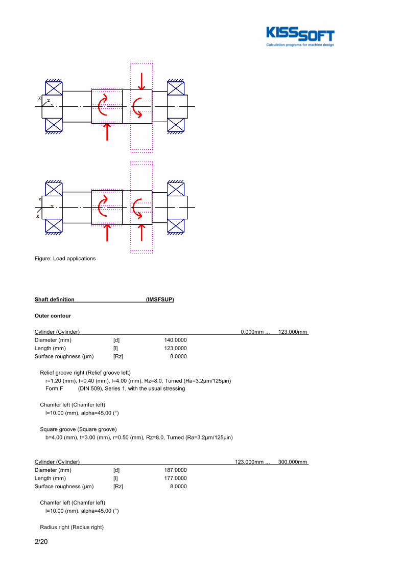
2/20
Figure: Load applications
Shaft definition (IMSFSUP)
Outer contour
Cylinder (Cylinder) 0.000mm ... 123.000mm Diameter (mm) [d] 140.0000Length (mm) [l] 123.0000Surface roughness (µm) [Rz] 8.0000
Relief groove right (Relief groove left) r=1.20 (mm), t=0.40 (mm), l=4.00 (mm), Rz=8.0, Turned (Ra=3.2μm/125μin) Form F (DIN 509), Series 1, with the usual stressing
Chamfer left (Chamfer left) l=10.00 (mm), alpha=45.00 (°)
Square groove (Square groove) b=4.00 (mm), t=3.00 (mm), r=0.50 (mm), Rz=8.0, Turned (Ra=3.2μm/125μin)
Cylinder (Cylinder) 123.000mm ... 300.000mm Diameter (mm) [d] 187.0000Length (mm) [l] 177.0000Surface roughness (µm) [Rz] 8.0000
Chamfer left (Chamfer left) l=10.00 (mm), alpha=45.00 (°)
Radius right (Radius right)
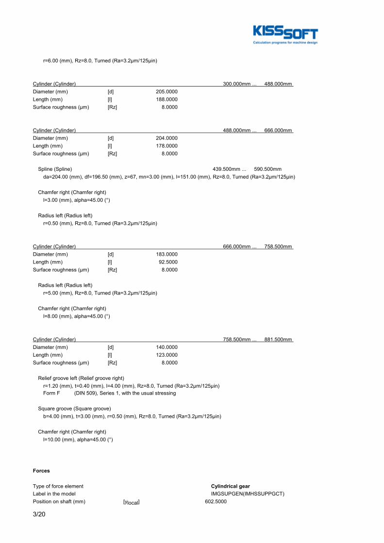
3/20
r=6.00 (mm), Rz=8.0, Turned (Ra=3.2μm/125μin)
Cylinder (Cylinder) 300.000mm ... 488.000mm Diameter (mm) [d] 205.0000Length (mm) [l] 188.0000Surface roughness (µm) [Rz] 8.0000
Cylinder (Cylinder) 488.000mm ... 666.000mm Diameter (mm) [d] 204.0000Length (mm) [l] 178.0000Surface roughness (µm) [Rz] 8.0000
Spline (Spline) 439.500mm ... 590.500mm da=204.00 (mm), df=196.50 (mm), z=67, mn=3.00 (mm), l=151.00 (mm), Rz=8.0, Turned (Ra=3.2μm/125μin)
Chamfer right (Chamfer right) l=3.00 (mm), alpha=45.00 (°)
Radius left (Radius left) r=0.50 (mm), Rz=8.0, Turned (Ra=3.2μm/125μin)
Cylinder (Cylinder) 666.000mm ... 758.500mm Diameter (mm) [d] 183.0000Length (mm) [l] 92.5000Surface roughness (µm) [Rz] 8.0000
Radius left (Radius left) r=5.00 (mm), Rz=8.0, Turned (Ra=3.2μm/125μin)
Chamfer right (Chamfer right) l=8.00 (mm), alpha=45.00 (°)
Cylinder (Cylinder) 758.500mm ... 881.500mm Diameter (mm) [d] 140.0000Length (mm) [l] 123.0000Surface roughness (µm) [Rz] 8.0000
Relief groove left (Relief groove right) r=1.20 (mm), t=0.40 (mm), l=4.00 (mm), Rz=8.0, Turned (Ra=3.2μm/125μin) Form F (DIN 509), Series 1, with the usual stressing
Square groove (Square groove) b=4.00 (mm), t=3.00 (mm), r=0.50 (mm), Rz=8.0, Turned (Ra=3.2μm/125μin)
Chamfer right (Chamfer right) l=10.00 (mm), alpha=45.00 (°)
Forces
Type of force element Cylindrical gearLabel in the model IMGSUPGEN(IMHSSUPPGCT)Position on shaft (mm) [ylocal] 602.5000

4/20
Position in global system (mm) [yglobal] 602.5000Operating pitch diameter (mm) 554.4000Helix angle (°) 25.1077 Double helical gearing, right-leftWorking pressure angle at normal section (°) 20.6227Position of contact (°) -112.0085Length of load application (mm) 133.0000Power (kW) 1210.0004Torque (Nm) 30907.5080Axial force (load spectrum) (N) 0.0000 / 0.0000 / 0.0000Shearing force X (load spectrum) (N) 73650.7723 / 45880.8090 / 27769.9633Shearing force Z (Load spectrum) (N) 718.8059 / 447.7807 / 271.0252Bending moment X (Load spectrum) (Nm) 0.0000 / 0.0000 / 0.0000Bending moment Z (Load spectrum) (Nm) 0.0000 / 0.0000 / 0.0000Load spectrum, driving (output)
No. Frequency (%) Speed (1/min) Power (kW) Torque (Nm) 1 1.2440e-003 -373.846 738.100 -18853.580 2 1.0330e-003 -373.846 459.800 -11744.853 3 1.0657e-002 -373.846 278.300 -7108.727 4 9.3936e+000 -373.846 -0.000 0.000 5 2.7248e+001 -373.846 -278.300 7108.727 6 1.9304e+001 -373.846 -544.500 13908.379 7 1.3095e+001 -373.846 -822.800 21017.105 8 2.3136e+001 -373.846 -1185.800 30289.358 9 7.7924e+000 -373.846 -1464.101 37398.085 10 1.8943e-002 -373.846 -1742.401 44506.812 11 5.5000e-005 -373.846 -2020.701 51615.538
Type of force element Cylindrical gearLabel in the model IMGSUPROT(LSIMSUPPGCT)Position on shaft (mm) [ylocal] 394.0000Position in global system (mm) [yglobal] 394.0000Operating pitch diameter (mm) 221.5517Helix angle (°) 25.0871 Double helical gearing, right-leftWorking pressure angle at normal section (°) 20.5050Position of contact (°) -30.0000Length of load application (mm) 188.0000Power (kW) 1210.0004Torque (Nm) -30907.5080Axial force (load spectrum) (N) 0.0000 / 0.0000 / 0.0000Shearing force X (load spectrum) (N) -145962.6767 / -90927.5691 / -55035.1076Shearing force Z (Load spectrum) (N) -112253.5208 / -69928.4228 / -42325.0980Bending moment X (Load spectrum) (Nm) 0.0000 / 0.0000 / 0.0000Bending moment Z (Load spectrum) (Nm) 0.0000 / 0.0000 / 0.0000Load spectrum, driven (input)
No. Frequency (%) Speed (1/min) Power (kW) Torque (Nm) 1 1.2440e-003 -373.846 -738.100 18853.580 2 1.0330e-003 -373.846 -459.800 11744.853 3 1.0657e-002 -373.846 -278.300 7108.727 4 9.3936e+000 -373.846 0.000 -0.000 5 2.7248e+001 -373.846 278.300 -7108.727 6 1.9304e+001 -373.846 544.500 -13908.379 7 1.3095e+001 -373.846 822.800 -21017.105 8 2.3136e+001 -373.846 1185.800 -30289.358 9 7.7924e+000 -373.846 1464.101 -37398.085 10 1.8943e-002 -373.846 1742.401 -44506.812
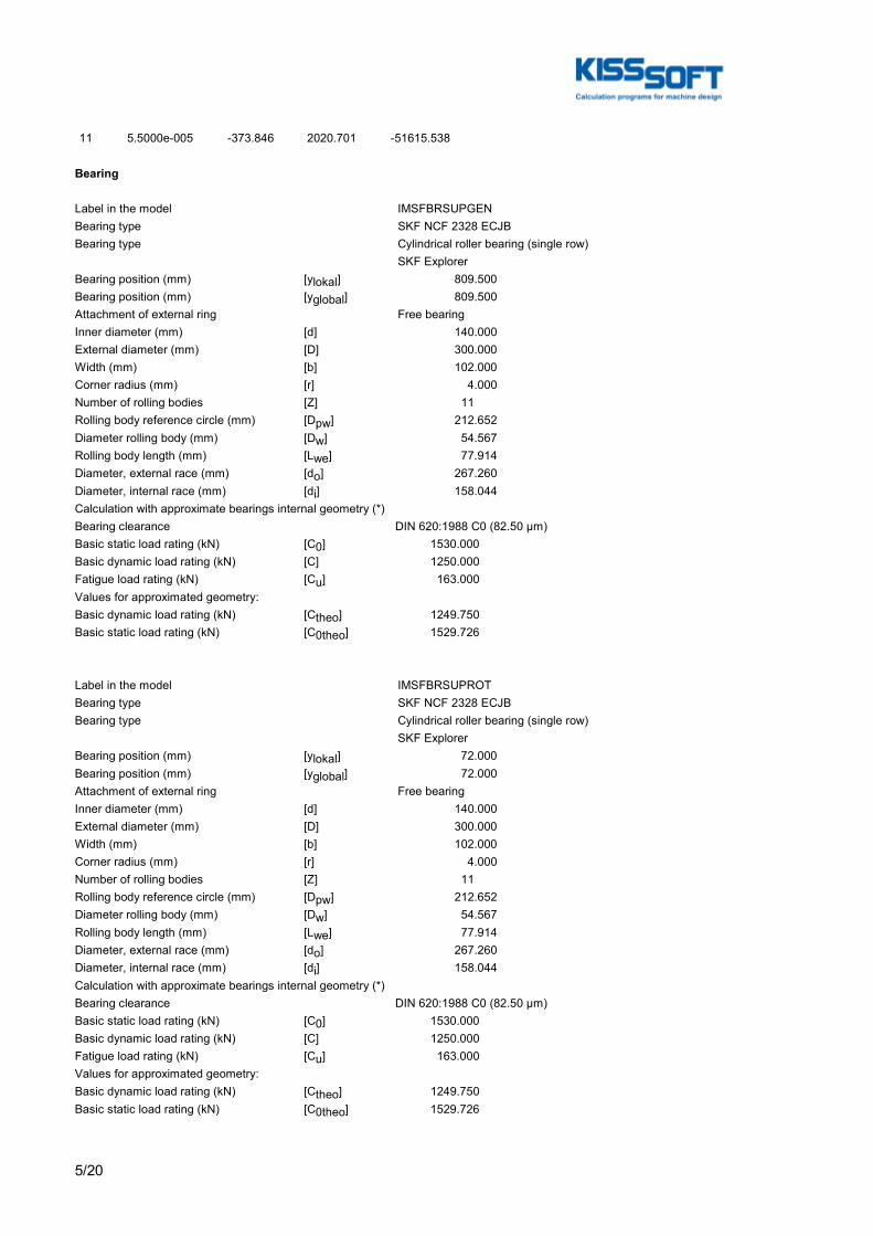
5/20
11 5.5000e-005 -373.846 2020.701 -51615.538
Bearing
Label in the model IMSFBRSUPGENBearing type SKF NCF 2328 ECJBBearing type Cylindrical roller bearing (single row) SKF ExplorerBearing position (mm) [ylokal] 809.500Bearing position (mm) [yglobal] 809.500Attachment of external ring Free bearingInner diameter (mm) [d] 140.000External diameter (mm) [D] 300.000Width (mm) [b] 102.000Corner radius (mm) [r] 4.000Number of rolling bodies [Z] 11Rolling body reference circle (mm) [Dpw] 212.652Diameter rolling body (mm) [Dw] 54.567Rolling body length (mm) [Lwe] 77.914Diameter, external race (mm) [do] 267.260Diameter, internal race (mm) [di] 158.044Calculation with approximate bearings internal geometry (*)Bearing clearance DIN 620:1988 C0 (82.50 µm)Basic static load rating (kN) [C0] 1530.000Basic dynamic load rating (kN) [C] 1250.000Fatigue load rating (kN) [Cu] 163.000Values for approximated geometry:Basic dynamic load rating (kN) [Ctheo] 1249.750Basic static load rating (kN) [C0theo] 1529.726
Label in the model IMSFBRSUPROTBearing type SKF NCF 2328 ECJBBearing type Cylindrical roller bearing (single row) SKF ExplorerBearing position (mm) [ylokal] 72.000Bearing position (mm) [yglobal] 72.000Attachment of external ring Free bearingInner diameter (mm) [d] 140.000External diameter (mm) [D] 300.000Width (mm) [b] 102.000Corner radius (mm) [r] 4.000Number of rolling bodies [Z] 11Rolling body reference circle (mm) [Dpw] 212.652Diameter rolling body (mm) [Dw] 54.567Rolling body length (mm) [Lwe] 77.914Diameter, external race (mm) [do] 267.260Diameter, internal race (mm) [di] 158.044Calculation with approximate bearings internal geometry (*)Bearing clearance DIN 620:1988 C0 (82.50 µm)Basic static load rating (kN) [C0] 1530.000Basic dynamic load rating (kN) [C] 1250.000Fatigue load rating (kN) [Cu] 163.000Values for approximated geometry:Basic dynamic load rating (kN) [Ctheo] 1249.750Basic static load rating (kN) [C0theo] 1529.726
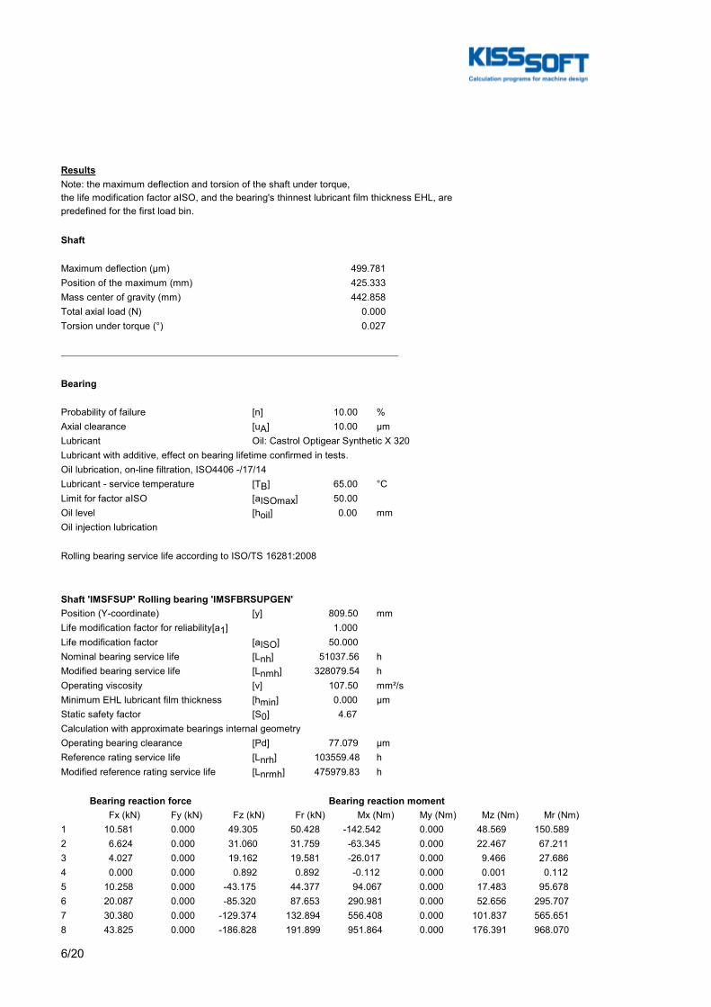
6/20
ResultsNote: the maximum deflection and torsion of the shaft under torque,the life modification factor aISO, and the bearing's thinnest lubricant film thickness EHL, arepredefined for the first load bin.
Shaft
Maximum deflection (μm) 499.781Position of the maximum (mm) 425.333Mass center of gravity (mm) 442.858Total axial load (N) 0.000Torsion under torque (°) 0.027
Bearing
Probability of failure [n] 10.00 %Axial clearance [uA] 10.00 µmLubricant Oil: Castrol Optigear Synthetic X 320Lubricant with additive, effect on bearing lifetime confirmed in tests.Oil lubrication, on-line filtration, ISO4406 -/17/14Lubricant - service temperature [TB] 65.00 °CLimit for factor aISO [aISOmax] 50.00Oil level [hoil] 0.00 mmOil injection lubrication
Rolling bearing service life according to ISO/TS 16281:2008
Shaft 'IMSFSUP' Rolling bearing 'IMSFBRSUPGEN'Position (Y-coordinate) [y] 809.50 mmLife modification factor for reliability[a1] 1.000Life modification factor [aISO] 50.000Nominal bearing service life [Lnh] 51037.56 hModified bearing service life [Lnmh] 328079.54 hOperating viscosity [ν] 107.50 mm²/sMinimum EHL lubricant film thickness [hmin] 0.000 µmStatic safety factor [S0] 4.67Calculation with approximate bearings internal geometryOperating bearing clearance [Pd] 77.079 µmReference rating service life [Lnrh] 103559.48 hModified reference rating service life [Lnrmh] 475979.83 h
Bearing reaction force Bearing reaction moment Fx (kN) Fy (kN) Fz (kN) Fr (kN) Mx (Nm) My (Nm) Mz (Nm) Mr (Nm)1 10.581 0.000 49.305 50.428 -142.542 0.000 48.569 150.5892 6.624 0.000 31.060 31.759 -63.345 0.000 22.467 67.2113 4.027 0.000 19.162 19.581 -26.017 0.000 9.466 27.6864 0.000 0.000 0.892 0.892 -0.112 0.000 0.001 0.1125 10.258 0.000 -43.175 44.377 94.067 0.000 17.483 95.6786 20.087 0.000 -85.320 87.653 290.981 0.000 52.656 295.7077 30.380 0.000 -129.374 132.894 556.408 0.000 101.837 565.6518 43.825 0.000 -186.828 191.899 951.864 0.000 176.391 968.070
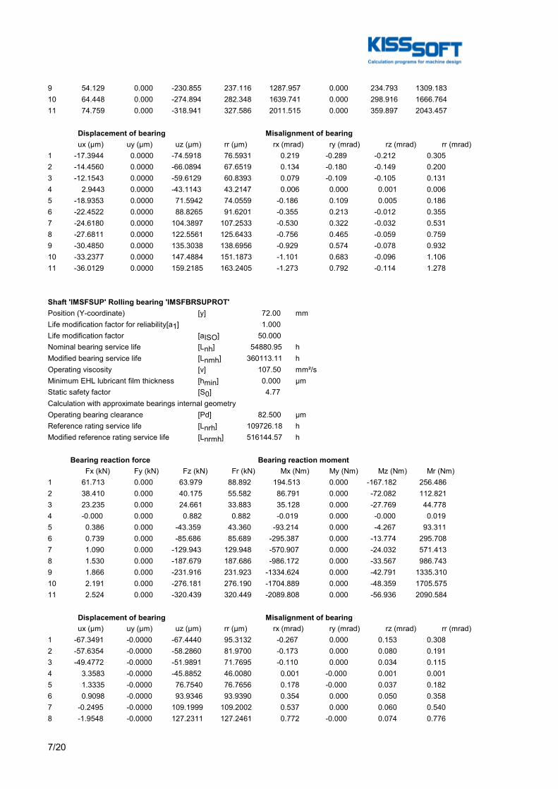
7/20
9 54.129 0.000 -230.855 237.116 1287.957 0.000 234.793 1309.18310 64.448 0.000 -274.894 282.348 1639.741 0.000 298.916 1666.76411 74.759 0.000 -318.941 327.586 2011.515 0.000 359.897 2043.457
Displacement of bearing Misalignment of bearing ux (µm) uy (µm) uz (µm) rr (µm) rx (mrad) ry (mrad) rz (mrad) rr (mrad)1 -17.3944 0.0000 -74.5918 76.5931 0.219 -0.289 -0.212 0.3052 -14.4560 0.0000 -66.0894 67.6519 0.134 -0.180 -0.149 0.2003 -12.1543 0.0000 -59.6129 60.8393 0.079 -0.109 -0.105 0.1314 2.9443 0.0000 -43.1143 43.2147 0.006 0.000 0.001 0.0065 -18.9353 0.0000 71.5942 74.0559 -0.186 0.109 0.005 0.1866 -22.4522 0.0000 88.8265 91.6201 -0.355 0.213 -0.012 0.3557 -24.6180 0.0000 104.3897 107.2533 -0.530 0.322 -0.032 0.5318 -27.6811 0.0000 122.5561 125.6433 -0.756 0.465 -0.059 0.7599 -30.4850 0.0000 135.3038 138.6956 -0.929 0.574 -0.078 0.93210 -33.2377 0.0000 147.4884 151.1873 -1.101 0.683 -0.096 1.10611 -36.0129 0.0000 159.2185 163.2405 -1.273 0.792 -0.114 1.278
Shaft 'IMSFSUP' Rolling bearing 'IMSFBRSUPROT'Position (Y-coordinate) [y] 72.00 mmLife modification factor for reliability[a1] 1.000Life modification factor [aISO] 50.000Nominal bearing service life [Lnh] 54880.95 hModified bearing service life [Lnmh] 360113.11 hOperating viscosity [ν] 107.50 mm²/sMinimum EHL lubricant film thickness [hmin] 0.000 µmStatic safety factor [S0] 4.77Calculation with approximate bearings internal geometryOperating bearing clearance [Pd] 82.500 µmReference rating service life [Lnrh] 109726.18 hModified reference rating service life [Lnrmh] 516144.57 h
Bearing reaction force Bearing reaction moment Fx (kN) Fy (kN) Fz (kN) Fr (kN) Mx (Nm) My (Nm) Mz (Nm) Mr (Nm)1 61.713 0.000 63.979 88.892 194.513 0.000 -167.182 256.4862 38.410 0.000 40.175 55.582 86.791 0.000 -72.082 112.8213 23.235 0.000 24.661 33.883 35.128 0.000 -27.769 44.7784 -0.000 0.000 0.882 0.882 -0.019 0.000 -0.000 0.0195 0.386 0.000 -43.359 43.360 -93.214 0.000 -4.267 93.3116 0.739 0.000 -85.686 85.689 -295.387 0.000 -13.774 295.7087 1.090 0.000 -129.943 129.948 -570.907 0.000 -24.032 571.4138 1.530 0.000 -187.679 187.686 -986.172 0.000 -33.567 986.7439 1.866 0.000 -231.916 231.923 -1334.624 0.000 -42.791 1335.31010 2.191 0.000 -276.181 276.190 -1704.889 0.000 -48.359 1705.57511 2.524 0.000 -320.439 320.449 -2089.808 0.000 -56.936 2090.584
Displacement of bearing Misalignment of bearing ux (µm) uy (µm) uz (µm) rr (µm) rx (mrad) ry (mrad) rz (mrad) rr (mrad)1 -67.3491 -0.0000 -67.4440 95.3132 -0.267 0.000 0.153 0.3082 -57.6354 -0.0000 -58.2860 81.9700 -0.173 0.000 0.080 0.1913 -49.4772 -0.0000 -51.9891 71.7695 -0.110 0.000 0.034 0.1154 3.3583 -0.0000 -45.8852 46.0080 0.001 -0.000 0.001 0.0015 1.3335 -0.0000 76.7540 76.7656 0.178 -0.000 0.037 0.1826 0.9098 -0.0000 93.9346 93.9390 0.354 0.000 0.050 0.3587 -0.2495 -0.0000 109.1999 109.2002 0.537 0.000 0.060 0.5408 -1.9548 -0.0000 127.2311 127.2461 0.772 -0.000 0.074 0.776
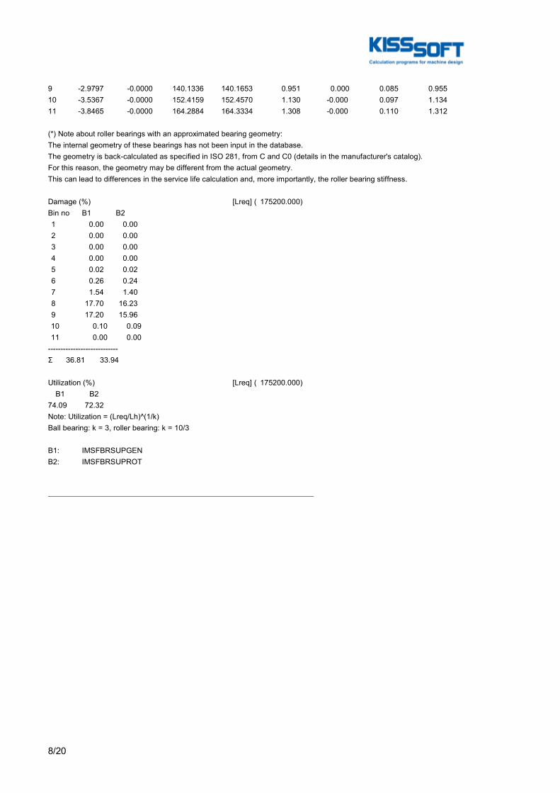
8/20
9 -2.9797 -0.0000 140.1336 140.1653 0.951 0.000 0.085 0.95510 -3.5367 -0.0000 152.4159 152.4570 1.130 -0.000 0.097 1.13411 -3.8465 -0.0000 164.2884 164.3334 1.308 -0.000 0.110 1.312
(*) Note about roller bearings with an approximated bearing geometry:The internal geometry of these bearings has not been input in the database.The geometry is back-calculated as specified in ISO 281, from C and C0 (details in the manufacturer's catalog).For this reason, the geometry may be different from the actual geometry.This can lead to differences in the service life calculation and, more importantly, the roller bearing stiffness.
Damage (%) [Lreq] ( 175200.000)Bin no B1 B2 1 0.00 0.00 2 0.00 0.00 3 0.00 0.00 4 0.00 0.00 5 0.02 0.02 6 0.26 0.24 7 1.54 1.40 8 17.70 16.23 9 17.20 15.96 10 0.10 0.09 11 0.00 0.00----------------------------Σ 36.81 33.94
Utilization (%) [Lreq] ( 175200.000) B1 B274.09 72.32Note: Utilization = (Lreq/Lh)^(1/k)Ball bearing: k = 3, roller bearing: k = 10/3
B 1: IMSFBRSUPGENB 2: IMSFBRSUPROT

9/20
Figure: Deformation (bending etc.) (Arbitrary plane 94.99318738 121)
Nominal stresses, without taking into account stress concentrationsGEH(von Mises): sigV = ((sigB+sigZ,D)^2 + 3*(tauT+tauS)^2)^1/2SSH(Tresca): sigV = ((sigB-sigZ,D)^2 + 4*(tauT+tauS)^2)^1/2
Figure: Equivalent stress

10/20
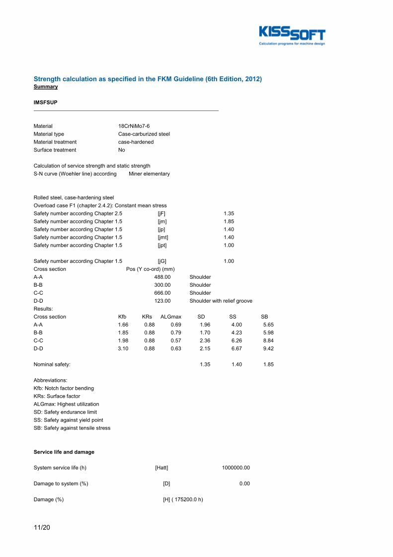
11/20
Strength calculation as specified in the FKM Guideline (6th Edition, 2012)Summary
IMSFSUP
Material 18CrNiMo7-6Material type Case-carburized steelMaterial treatment case-hardenedSurface treatment No
Calculation of service strength and static strengthS-N curve (Woehler line) according Miner elementary
Rolled steel, case-hardening steelOverload case F1 (chapter 2.4.2): Constant mean stressSafety number according Chapter 2.5 [jF] 1.35Safety number according Chapter 1.5 [jm] 1.85Safety number according Chapter 1.5 [jp] 1.40Safety number according Chapter 1.5 [jmt] 1.40Safety number according Chapter 1.5 [jpt] 1.00
Safety number according Chapter 1.5 [jG] 1.00Cross section Pos (Y co-ord) (mm)A-A 488.00 ShoulderB-B 300.00 ShoulderC-C 666.00 ShoulderD-D 123.00 Shoulder with relief grooveResults:Cross section Kfb KRs ALGmax SD SS SBA-A 1.66 0.88 0.69 1.96 4.00 5.65B-B 1.85 0.88 0.79 1.70 4.23 5.98C-C 1.98 0.88 0.57 2.36 6.26 8.84D-D 3.10 0.88 0.63 2.15 6.67 9.42
Nominal safety: 1.35 1.40 1.85
Abbreviations:Kfb: Notch factor bendingKRs: Surface factorALGmax: Highest utilizationSD: Safety endurance limitSS: Safety against yield pointSB: Safety against tensile stress
Service life and damage
System service life (h) [Hatt] 1000000.00
Damage to system (%) [D] 0.00
Damage (%) [H] ( 175200.0 h)

12/20
Calculation of reliability R(t) using a Weibull distribution; t in (h): R(t) = 100 * Exp(-((t*fac - t0)/(T - t0))^b) %Welle fac b t0 T1 22431 1.5 2.045e+010 4.338e+010
Damage to cross sections (%) [D]A-A: 0.00B-B: 0.00C-C: 0.00D-D: 0.00
Utilization (%) [Smin/S]
Cross section Static EnduranceA-A 35.009 69.030B-B 33.060 79.213C-C 22.348 57.130D-D 20.983 62.814
Maximum utilization (%) [A] 79.213
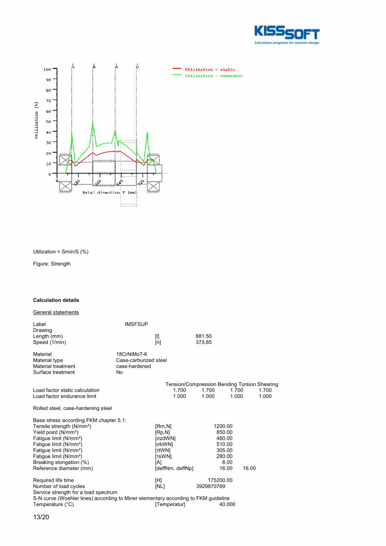
13/20
Utilization = Smin/S (%)
Figure: Strength
Calculation details
General statements
Label IMSFSUPDrawingLength (mm) [l] 881.50Speed (1/min) [n] 373.85
Material 18CrNiMo7-6Material type Case-carburized steelMaterial treatment case-hardenedSurface treatment No
Tension/Compression Bending Torsion ShearingLoad factor static calculation 1.700 1.700 1.700 1.700Load factor endurance limit 1.000 1.000 1.000 1.000
Rolled steel, case-hardening steel
Base stress according FKM chapter 5.1:Tensile strength (N/mm²) [Rm,N] 1200.00Yield point (N/mm²) [Rp,N] 850.00Fatigue limit (N/mm²) [σzdWN] 480.00Fatigue limit (N/mm²) [σbWN] 510.00Fatigue limit (N/mm²) [τtWN] 305.00Fatigue limit (N/mm²) [τsWN] 280.00Breaking elongation (%) [A] 8.00Reference diameter (mm) [deffNm, deffNp] 16.00 16.00
Required life time [H] 175200.00Number of load cycles [NL] 3929870769Service strength for a load spectrumS-N curve (Woehler lines) according to Miner elementary according to FKM guidelineTemperature (°C) [Temperatur] 40.000

14/20
Temperature duration (h) [TemperaturD] 175200.000Temperature coefficients [KTm, KTp, KTD] 1.000 1.000 1.000 [KTtm, KTtp] 1.000 1.000Internal stress coefficient [KEs, KEt] 1.000 1.000Additional coefficients [KA, KW, KfW] 1.000 1.000 1.000 [KNL, KNLE] 1.000 1.000Protective layer factor [KS] 1.000
Material properties: [fσZ, fσD, fτ, Rpmax] 1.000 1.000 0.577 1150.0 [fWt, fWs] 0.577 0.400 [aM, bM, aTD] 0.35000 -0.100 1.400 [aG, bG, aRsig, RmNmin] 0.500 2700.0 0.220 400.0 [MS, MT] 0.1727 0.0997 [kσ, kτ] 15 25 [kDσ, kDτ] 0 0 [NDσ, NDτ] 1e+006 1e+006 [NDσII, NDτII] 0 0
Thickness of raw material (mm) [d.eff] 210.00Material data calculated acc. FKM directive with Kdm, KdpGeometric size factors (Kdm, Kdp) calculated from raw diameterMaterial strength calculated from size of raw materialConstants [adm, adp] 0.370 0.370Size factors [Kdm, Kdp] 0.649 0.649Tensile strength (N/mm²) [Rm] 779.05Yield point (N/mm²) [Rp] 551.83σzdW (N/mm²) [σzdW] 311.62σbW (N/mm²) [σbW] 331.10τtW (N/mm²) [τtW] 198.01τsW (N/mm²) [τsW] 181.78
Overload case F1 (chapter 2.4.2): Constant mean stressSafety number according Chapter 1.5 [jm] 1.85Safety number according Chapter 1.5 [jp] 1.40Safety number according Chapter 1.5 [jmt] 1.40Safety number according Chapter 1.5 [jpt] 1.00Safety number according Chapter 2.5 [jF] 1.35
Safety number according Chapter 1.5 [jG] 1.00
Cross section 'A-A' ShoulderComment Y= 488.00mmPosition (Y-Coordinate) (mm) [y] 488.000External diameter (mm) [da] 204.000Inner diameter (mm) [di] 0.000Notch effect Shoulder[D, r, t] (mm) 205.000 0.500 0.500Mean roughness (µm) [Rz] 8.000
Tension/Compression Bending Torsion ShearingLoad: (N) (Nm)Mean value [Fzdm, Mbm, Tm, Fqm] -0.0 0.0 51615.5 0.0Amplitude [Fzda, Mba, Ta, Fqa] 0.0 84762.2 0.0 191042.9Maximum value [Fzdmax, Mbmax, Tmax, Fqmax] -0.0 144095.8 87746.4 324772.9Cross section, moment of resistance: (mm²)[A, Wb, Wt, A] 32685.1 833470.8 1666941.6 32685.1
Load spectrum, load base values (Mean-value + Amplitude):No. Frequency (%) Tens./Compres. (N) Bending (Nm) Torsion (Nm) Shearing (N) 1 1.2440e-003 -0.000 19600.924 -18853.580 97570.958 2 1.0330e-003 -0.000 12291.408 -11744.853 60835.960 3 1.0657e-002 -0.000 7507.616 -7108.727 36864.903 4 9.3936e+000 -0.000 156.866 0.000 113.367 5 2.7248e+001 -0.000 11728.933 7108.727 26251.423 6 1.9304e+001 -0.000 22987.724 13908.379 51449.797 7 1.3095e+001 -0.000 34696.361 21017.105 77781.916 8 2.3136e+001 -0.000 49916.210 30289.358 112112.866 9 7.7924e+000 -0.000 61545.272 37398.085 138415.617 10 1.8943e-002 -0.000 73162.529 44506.812 164724.355 11 5.5000e-005 -0.000 84762.242 51615.538 191042.894

15/20
Stresses: (N/mm²)[σmz, σmb, τmt, τms] -0.000 0.000 30.964 0.000[σaz, σab, τat, τas] 0.000 101.698 0.000 7.793[σzmax, σbmax, τtmax, τsmax] -0.000 172.886 52.639 13.249
FATIQUE PROOF:Total safety factor according chapter 2.5.3 [jD] 1.350(Formula: jD = jF*jG/KTD)
Tension/Compression Bending Torsion ShearingStress concentration factor [a] 2.253 2.086 1.472 1.236References stress slope [G'] 5.367 5.367 2.300 2.300Support number [n(r)] 1.248 1.248 1.265 1.265Support number [n(d)] 1.005 1.005 1.007 1.007Mechanical material support factor [nwm] 1.059 1.059 1.059 1.059The support factor is determined with the support factor as defined by Stieler.Notch effect coefficient beta [Kf] 1.805 1.664 1.156 1.000Roughness factor [KR] 0.883 0.883 0.932 0.932Surface stabilization factor [KV] 1.200 1.200 1.100 1.100Design coefficient [KWK] 1.615 1.497 1.117 0.975Fatigue limit of part (N/mm²) [SWK] 192.916 208.149 162.801 186.411
Calculation with principal mean stress:Mean stress coefficient [KAK] 0.952 0.956 0.981 0.983Permissible amplitude (N/mm²) [SAK] 183.656 198.889 159.714 183.324Effective Miner sum [DM] 0.3 0.33 0.3 0.3Coefficient service strength [KBK] 1.000 1.000 1.038 1.038Permissible amplitude (N/mm²) [SBK] 183.656 198.889 165.794 190.302Rate of utilization [aBK] 0.000 0.690 0.000 0.055
Calculation of the combined stress types:Rate of utilization for the combined load componentsa)For outer surface (shear stress = 0) Equivalent mean stress (N/mm²) [SmV_1] 53.632 Rate of utilization [aBKv_1] 0.690b) For neutral line (Bending stress = 0) Equivalent mean stress (N/mm²) [SmV_2] 53.632 Rate of utilization [aBKv_2] 0.055
Highest utilization [aBKmax] 0.690Safety endurance limit assessment [S.Dauer] 1.956Required safety [jD] 1.350Result (%) [S/jD] 144.9
STATIC STRENGTH ASSESSMENT:Total safety factor according chapter 1.5.3 [jges] 1.400(Formula: jges = jG*Max(jm/KTm*Rp/Rm, jp/KTp, jmt/KTtm*Rp/Rm, jpt/KTtp))
Tension/Compression Bending Torsion ShearingPlastic notch factor [Kpb, Kpt] 1.700 1.330Plastic support number [npl] 1.0000 1.4436 1.3300 1.0000Strength of part (N/mm²) [SSK] 551.83 796.62 423.73 318.60Rate of utilization [aSK] 0.000 0.304 0.174 0.058
Rate of utilization for the combined load components:a)For outer surface (shear stress = 0) Equivalent stress (N/mm²) [SvBn] 195.454 Rate of utilization [aSKvBn] 0.350b) For neutral line (Bending stress = 0) Equivalent stress (N/mm²) [SvQn] 114.121 Rate of utilization [aSKvQn] 0.232
Highest utilization [aSKmax] 0.350
Safety for fracture and yield stresses:Safety against fracture [S.Rm] 5.646Required safety [jm/Ktm] 1.850Result (%) [S/jm] 305.2
Safety against yield point [S.Rp] 3.999
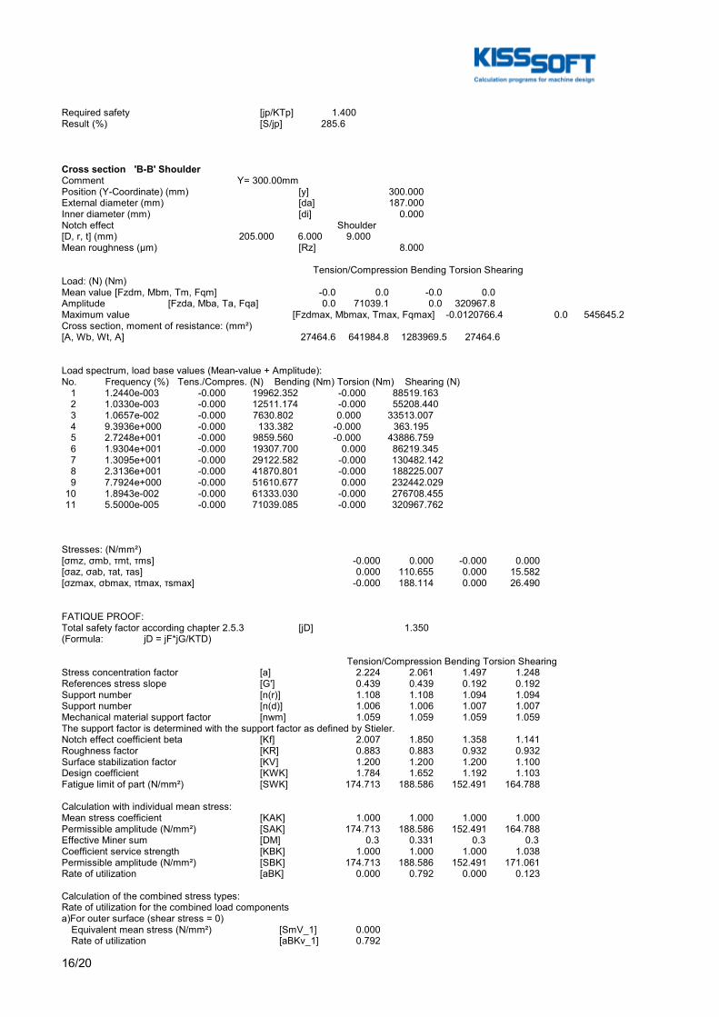
16/20
Required safety [jp/KTp] 1.400Result (%) [S/jp] 285.6
Cross section 'B-B' ShoulderComment Y= 300.00mmPosition (Y-Coordinate) (mm) [y] 300.000External diameter (mm) [da] 187.000Inner diameter (mm) [di] 0.000Notch effect Shoulder[D, r, t] (mm) 205.000 6.000 9.000Mean roughness (µm) [Rz] 8.000
Tension/Compression Bending Torsion ShearingLoad: (N) (Nm)Mean value [Fzdm, Mbm, Tm, Fqm] -0.0 0.0 -0.0 0.0Amplitude [Fzda, Mba, Ta, Fqa] 0.0 71039.1 0.0 320967.8Maximum value [Fzdmax, Mbmax, Tmax, Fqmax] -0.0 120766.4 0.0 545645.2Cross section, moment of resistance: (mm²)[A, Wb, Wt, A] 27464.6 641984.8 1283969.5 27464.6
Load spectrum, load base values (Mean-value + Amplitude):No. Frequency (%) Tens./Compres. (N) Bending (Nm) Torsion (Nm) Shearing (N) 1 1.2440e-003 -0.000 19962.352 -0.000 88519.163 2 1.0330e-003 -0.000 12511.174 -0.000 55208.440 3 1.0657e-002 -0.000 7630.802 0.000 33513.007 4 9.3936e+000 -0.000 133.382 -0.000 363.195 5 2.7248e+001 -0.000 9859.560 -0.000 43886.759 6 1.9304e+001 -0.000 19307.700 0.000 86219.345 7 1.3095e+001 -0.000 29122.582 -0.000 130482.142 8 2.3136e+001 -0.000 41870.801 -0.000 188225.007 9 7.7924e+000 -0.000 51610.677 0.000 232442.029 10 1.8943e-002 -0.000 61333.030 -0.000 276708.455 11 5.5000e-005 -0.000 71039.085 -0.000 320967.762
Stresses: (N/mm²)[σmz, σmb, τmt, τms] -0.000 0.000 -0.000 0.000[σaz, σab, τat, τas] 0.000 110.655 0.000 15.582[σzmax, σbmax, τtmax, τsmax] -0.000 188.114 0.000 26.490
FATIQUE PROOF:Total safety factor according chapter 2.5.3 [jD] 1.350(Formula: jD = jF*jG/KTD)
Tension/Compression Bending Torsion ShearingStress concentration factor [a] 2.224 2.061 1.497 1.248References stress slope [G'] 0.439 0.439 0.192 0.192Support number [n(r)] 1.108 1.108 1.094 1.094Support number [n(d)] 1.006 1.006 1.007 1.007Mechanical material support factor [nwm] 1.059 1.059 1.059 1.059The support factor is determined with the support factor as defined by Stieler.Notch effect coefficient beta [Kf] 2.007 1.850 1.358 1.141Roughness factor [KR] 0.883 0.883 0.932 0.932Surface stabilization factor [KV] 1.200 1.200 1.200 1.100Design coefficient [KWK] 1.784 1.652 1.192 1.103Fatigue limit of part (N/mm²) [SWK] 174.713 188.586 152.491 164.788
Calculation with individual mean stress:Mean stress coefficient [KAK] 1.000 1.000 1.000 1.000Permissible amplitude (N/mm²) [SAK] 174.713 188.586 152.491 164.788Effective Miner sum [DM] 0.3 0.331 0.3 0.3Coefficient service strength [KBK] 1.000 1.000 1.000 1.038Permissible amplitude (N/mm²) [SBK] 174.713 188.586 152.491 171.061Rate of utilization [aBK] 0.000 0.792 0.000 0.123
Calculation of the combined stress types:Rate of utilization for the combined load componentsa)For outer surface (shear stress = 0) Equivalent mean stress (N/mm²) [SmV_1] 0.000 Rate of utilization [aBKv_1] 0.792
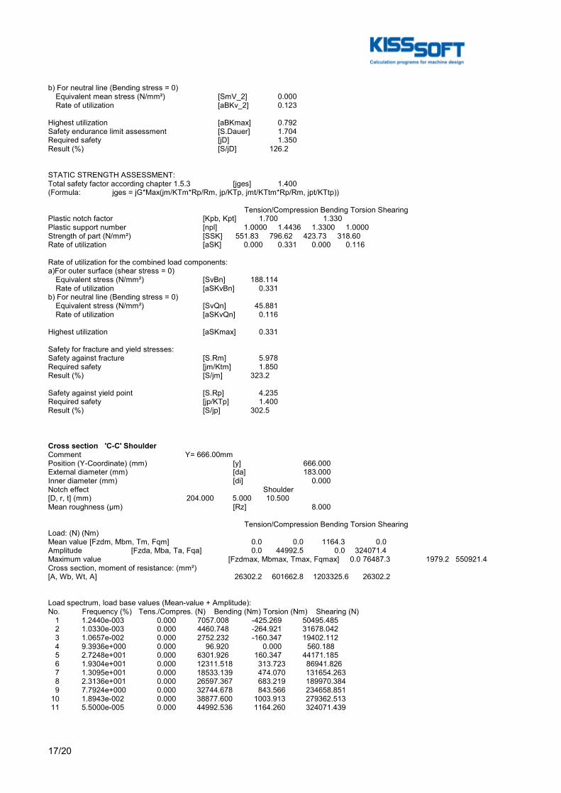
17/20
b) For neutral line (Bending stress = 0) Equivalent mean stress (N/mm²) [SmV_2] 0.000 Rate of utilization [aBKv_2] 0.123
Highest utilization [aBKmax] 0.792Safety endurance limit assessment [S.Dauer] 1.704Required safety [jD] 1.350Result (%) [S/jD] 126.2
STATIC STRENGTH ASSESSMENT:Total safety factor according chapter 1.5.3 [jges] 1.400(Formula: jges = jG*Max(jm/KTm*Rp/Rm, jp/KTp, jmt/KTtm*Rp/Rm, jpt/KTtp))
Tension/Compression Bending Torsion ShearingPlastic notch factor [Kpb, Kpt] 1.700 1.330Plastic support number [npl] 1.0000 1.4436 1.3300 1.0000Strength of part (N/mm²) [SSK] 551.83 796.62 423.73 318.60Rate of utilization [aSK] 0.000 0.331 0.000 0.116
Rate of utilization for the combined load components:a)For outer surface (shear stress = 0) Equivalent stress (N/mm²) [SvBn] 188.114 Rate of utilization [aSKvBn] 0.331b) For neutral line (Bending stress = 0) Equivalent stress (N/mm²) [SvQn] 45.881 Rate of utilization [aSKvQn] 0.116
Highest utilization [aSKmax] 0.331
Safety for fracture and yield stresses:Safety against fracture [S.Rm] 5.978Required safety [jm/Ktm] 1.850Result (%) [S/jm] 323.2
Safety against yield point [S.Rp] 4.235Required safety [jp/KTp] 1.400Result (%) [S/jp] 302.5
Cross section 'C-C' ShoulderComment Y= 666.00mmPosition (Y-Coordinate) (mm) [y] 666.000External diameter (mm) [da] 183.000Inner diameter (mm) [di] 0.000Notch effect Shoulder[D, r, t] (mm) 204.000 5.000 10.500Mean roughness (µm) [Rz] 8.000
Tension/Compression Bending Torsion ShearingLoad: (N) (Nm)Mean value [Fzdm, Mbm, Tm, Fqm] 0.0 0.0 1164.3 0.0Amplitude [Fzda, Mba, Ta, Fqa] 0.0 44992.5 0.0 324071.4Maximum value [Fzdmax, Mbmax, Tmax, Fqmax] 0.0 76487.3 1979.2 550921.4Cross section, moment of resistance: (mm²)[A, Wb, Wt, A] 26302.2 601662.8 1203325.6 26302.2
Load spectrum, load base values (Mean-value + Amplitude):No. Frequency (%) Tens./Compres. (N) Bending (Nm) Torsion (Nm) Shearing (N) 1 1.2440e-003 0.000 7057.008 -425.269 50495.485 2 1.0330e-003 0.000 4460.748 -264.921 31678.042 3 1.0657e-002 0.000 2752.232 -160.347 19402.112 4 9.3936e+000 0.000 96.920 0.000 560.188 5 2.7248e+001 0.000 6301.926 160.347 44171.185 6 1.9304e+001 0.000 12311.518 313.723 86941.826 7 1.3095e+001 0.000 18533.139 474.070 131654.263 8 2.3136e+001 0.000 26597.367 683.219 189970.384 9 7.7924e+000 0.000 32744.678 843.566 234658.851 10 1.8943e-002 0.000 38877.600 1003.913 279362.513 11 5.5000e-005 0.000 44992.536 1164.260 324071.439

18/20
Stresses: (N/mm²)[σmz, σmb, τmt, τms] 0.000 0.000 0.968 0.000[σaz, σab, τat, τas] 0.000 74.780 0.000 16.428[σzmax, σbmax, τtmax, τsmax] 0.000 127.127 1.645 27.928
FATIQUE PROOF:Total safety factor according chapter 2.5.3 [jD] 1.350(Formula: jD = jF*jG/KTD)
Tension/Compression Bending Torsion ShearingStress concentration factor [a] 2.403 2.224 1.580 1.290References stress slope [G'] 0.519 0.519 0.230 0.230Support number [n(r)] 1.117 1.117 1.103 1.103Support number [n(d)] 1.006 1.006 1.007 1.007Mechanical material support factor [nwm] 1.059 1.059 1.059 1.059The support factor is determined with the support factor as defined by Stieler.Notch effect coefficient beta [Kf] 2.151 1.980 1.421 1.169Roughness factor [KR] 0.883 0.883 0.932 0.932Surface stabilization factor [KV] 1.200 1.200 1.200 1.100Design coefficient [KWK] 1.903 1.761 1.245 1.129Fatigue limit of part (N/mm²) [SWK] 163.734 176.997 146.037 161.043
Calculation with principal mean stress:Mean stress coefficient [KAK] 0.998 0.998 0.999 0.999Permissible amplitude (N/mm²) [SAK] 163.445 176.708 145.941 160.946Effective Miner sum [DM] 0.3 0.333 0.3 0.3Coefficient service strength [KBK] 1.000 1.000 1.038 1.038Permissible amplitude (N/mm²) [SBK] 163.445 176.708 151.496 167.073Rate of utilization [aBK] 0.000 0.571 0.000 0.133
Calculation of the combined stress types:Rate of utilization for the combined load componentsa)For outer surface (shear stress = 0) Equivalent mean stress (N/mm²) [SmV_1] 1.676 Rate of utilization [aBKv_1] 0.571b) For neutral line (Bending stress = 0) Equivalent mean stress (N/mm²) [SmV_2] 1.676 Rate of utilization [aBKv_2] 0.133
Highest utilization [aBKmax] 0.571Safety endurance limit assessment [S.Dauer] 2.363Required safety [jD] 1.350Result (%) [S/jD] 175.0
STATIC STRENGTH ASSESSMENT:Total safety factor according chapter 1.5.3 [jges] 1.400(Formula: jges = jG*Max(jm/KTm*Rp/Rm, jp/KTp, jmt/KTtm*Rp/Rm, jpt/KTtp))
Tension/Compression Bending Torsion ShearingPlastic notch factor [Kpb, Kpt] 1.700 1.330Plastic support number [npl] 1.0000 1.4436 1.3300 1.0000Strength of part (N/mm²) [SSK] 551.83 796.62 423.73 318.60Rate of utilization [aSK] 0.000 0.223 0.005 0.123
Rate of utilization for the combined load components:a)For outer surface (shear stress = 0) Equivalent stress (N/mm²) [SvBn] 127.158 Rate of utilization [aSKvBn] 0.223b) For neutral line (Bending stress = 0) Equivalent stress (N/mm²) [SvQn] 51.221 Rate of utilization [aSKvQn] 0.128
Highest utilization [aSKmax] 0.223
Safety for fracture and yield stresses:Safety against fracture [S.Rm] 8.844Required safety [jm/Ktm] 1.850Result (%) [S/jm] 478.1
Safety against yield point [S.Rp] 6.264Required safety [jp/KTp] 1.400Result (%) [S/jp] 447.5

19/20
Cross section 'D-D' Shoulder with relief grooveComment Y= 123.00mmPosition (Y-Coordinate) (mm) [y] 123.000External diameter (mm) [da] 140.000Inner diameter (mm) [di] 0.000Notch effect Shoulder with relief groove[D, d, D1, r, t1] (mm) 187.000 139.200 140.000 1.200 Qu[3].Geo.tShape BMean roughness (µm) [Rz] 8.000
Tension/Compression Bending Torsion ShearingLoad: (N) (Nm)Mean value [Fzdm, Mbm, Tm, Fqm] -0.0 0.0 -0.0 0.0Amplitude [Fzda, Mba, Ta, Fqa] 0.0 14260.9 0.0 320594.4Maximum value [Fzdmax, Mbmax, Tmax, Fqmax] -0.0 24243.5 0.0 545010.5Cross section, moment of resistance: (mm²)[A, Wb, Wt, A] 15218.4 264799.8 529599.5 15218.4
Load spectrum, load base values (Mean-value + Amplitude):No. Frequency (%) Tens./Compres. (N) Bending (Nm) Torsion (Nm) Shearing (N) 1 1.2440e-003 -0.000 4270.765 -0.000 88787.198 2 1.0330e-003 -0.000 2715.521 -0.000 55477.224 3 1.0657e-002 -0.000 1675.148 0.000 33783.012 4 9.3936e+000 -0.000 36.056 -0.000 736.540 5 2.7248e+001 -0.000 2124.646 -0.000 43513.428 6 1.9304e+001 -0.000 4079.929 0.000 85846.014 7 1.3095e+001 -0.000 6060.308 -0.000 130108.810 8 2.3136e+001 -0.000 8588.047 -0.000 187851.674 9 7.7924e+000 -0.000 10501.517 0.000 232068.696 10 1.8943e-002 -0.000 12388.713 -0.000 276335.121 11 5.5000e-005 -0.000 14260.877 -0.000 320594.429
Stresses: (N/mm²)[σmz, σmb, τmt, τms] -0.000 0.000 -0.000 0.000[σaz, σab, τat, τas] 0.000 53.855 0.000 28.088[σzmax, σbmax, τtmax, τsmax] -0.000 91.554 0.000 47.750
FATIQUE PROOF:Total safety factor according chapter 2.5.3 [jD] 1.350(Formula: jD = jF*jG/KTD)
Tension/Compression Bending Torsion ShearingStress concentration factor [a] 4.269 3.725 2.398 1.699References stress slope [G'] 2.013 2.013 0.958 0.958Support number [n(r)] 1.194 1.194 1.211 1.211Support number [n(d)] 1.007 1.007 1.010 1.010Mechanical material support factor [nwm] 1.059 1.059 1.059 1.059The support factor is determined with the support factor as defined by Stieler.Notch effect coefficient beta [Kf] 3.576 3.098 1.961 1.403Roughness factor [KR] 0.883 0.883 0.932 0.932Surface stabilization factor [KV] 1.200 1.200 1.200 1.200Design coefficient [KWK] 3.091 2.692 1.695 1.230Fatigue limit of part (N/mm²) [SWK] 100.825 115.747 107.246 147.812
Calculation with individual mean stress:Mean stress coefficient [KAK] 1.000 1.000 1.000 1.000Permissible amplitude (N/mm²) [SAK] 100.825 115.747 107.246 147.812Effective Miner sum [DM] 0.3 0.349 0.3 0.3Coefficient service strength [KBK] 1.000 1.000 1.000 1.038Permissible amplitude (N/mm²) [SBK] 100.825 115.747 107.246 153.438Rate of utilization [aBK] 0.000 0.628 0.000 0.247
Calculation of the combined stress types:Rate of utilization for the combined load componentsa)For outer surface (shear stress = 0) Equivalent mean stress (N/mm²) [SmV_1] 0.000 Rate of utilization [aBKv_1] 0.628b) For neutral line (Bending stress = 0) Equivalent mean stress (N/mm²) [SmV_2] 0.000

20/20
Rate of utilization [aBKv_2] 0.247
Highest utilization [aBKmax] 0.628Safety endurance limit assessment [S.Dauer] 2.149Required safety [jD] 1.350Result (%) [S/jD] 159.2
STATIC STRENGTH ASSESSMENT:Total safety factor according chapter 1.5.3 [jges] 1.400(Formula: jges = jG*Max(jm/KTm*Rp/Rm, jp/KTp, jmt/KTtm*Rp/Rm, jpt/KTtp))
Tension/Compression Bending Torsion ShearingPlastic notch factor [Kpb, Kpt] 1.700 1.330Plastic support number [npl] 1.0000 1.1597 1.3300 1.0000Strength of part (N/mm²) [SSK] 551.83 639.95 423.73 318.60Rate of utilization [aSK] 0.000 0.200 0.000 0.210
Rate of utilization for the combined load components:a)For outer surface (shear stress = 0) Equivalent stress (N/mm²) [SvBn] 91.554 Rate of utilization [aSKvBn] 0.200b) For neutral line (Bending stress = 0) Equivalent stress (N/mm²) [SvQn] 82.706 Rate of utilization [aSKvQn] 0.210
Highest utilization [aSKmax] 0.210
Safety for fracture and yield stresses:Safety against fracture [S.Rm] 9.419Required safety [jm/Ktm] 1.850Result (%) [S/jm] 509.2
Safety against yield point [S.Rp] 6.672Required safety [jp/KTp] 1.400Result (%) [S/jp] 476.6
Important remarks concerning strength calculation according to FKM-Guideline:
- Calculation with nominal stresses- Regulation for proof: Utilization <= 1- Currently the following restrictions still apply:: Only for axially symmetrical shafts- Assumption for calculating the notch factor for shearing: ßS = 1.0 + (ßT - 1.0) / 2.0 (according to Prof. Haibach)- Thread: Determination of notch factor as circumferential groove- Slight interference fit: determination of the notch factor according to fig. 5.3.11 b) with p = 20MPa- Proven safety: Effective safety according to special formula, condition: safety > required safety or result > 100%
End of Report lines: 1023

A.2. KISSsoft Reports - Shaft calculation
A.2.4 KISSsoft Report - Intermediate shaft (inferior branch)
231

A. KISSsoft Reports
232
1/23
KISSsoft Release 03/2017 A KISSsoft University license - Universidade do Porto File Name : UnnamedChanged by: Joana Mêda de Sousa on: 09.10.2017 at: 22:27:44
Analysis of shafts, axle and beams
Input data
Coordinate system shaft: see picture W-002
Label IMSFINFDrawingInitial position (mm) 0.000Length (mm) 881.500Speed (1/min) 373.85Sense of rotation: counter clockwise
Material 18CrNiMo7-6Young's modulus (N/mm²) 206000.000Poisson's ratio nu 0.300Density (kg/m³) 7830.000Coefficient of thermal expansion (10^-6/K) 11.500Temperature (°C) 20.000Weight of shaft (kg) 180.286Weight of shaft, including additional masses (kg) 180.286Mass moment of inertia (kg*m²) 0.806Momentum of mass GD2 (Nm²) 31.623
Weight towards ( 0.000, 0.000, -1.000)Consider deformations due to shearingShear correction coefficient 1.100Rolling bearing stiffness is calculated from inner bearing geometryTolerance field: Mean valueReference temperature (°C) 40.000

2/23
Figure: Load applications
Shaft definition (IMSFINF)
Outer contour
Cylinder (Cylinder) 0.000mm ... 123.000mm Diameter (mm) [d] 140.0000Length (mm) [l] 123.0000Surface roughness (µm) [Rz] 8.0000
Relief groove right (Relief groove right) r=1.20 (mm), t=0.40 (mm), l=4.00 (mm), Rz=8.0, Turned (Ra=3.2μm/125μin) Form F (DIN 509), Series 1, with the usual stressing
Chamfer left (Chamfer left) l=10.00 (mm), alpha=45.00 (°)
Square groove (Square groove) b=4.00 (mm), t=3.00 (mm), r=0.50 (mm), Rz=8.0, Turned (Ra=3.2μm/125μin)
Cylinder (Cylinder) 123.000mm ... 300.000mm Diameter (mm) [d] 187.0000Length (mm) [l] 177.0000Surface roughness (µm) [Rz] 8.0000
Radius right (Radius right) r=6.00 (mm), Rz=8.0, Turned (Ra=3.2μm/125μin)
Chamfer left (Chamfer left)

3/23
l=10.00 (mm), alpha=45.00 (°)
Cylinder (Cylinder) 300.000mm ... 488.000mm Diameter (mm) [d] 205.0000Length (mm) [l] 188.0000Surface roughness (µm) [Rz] 8.0000
Cylinder (Cylinder) 488.000mm ... 666.000mm Diameter (mm) [d] 204.0000Length (mm) [l] 178.0000Surface roughness (µm) [Rz] 8.0000
Radius left (Radius left) r=0.50 (mm), Rz=8.0, Turned (Ra=3.2μm/125μin)
Spline (Spline) 439.500mm ... 590.500mm da=204.00 (mm), df=196.50 (mm), z=67, mn=3.00 (mm), l=151.00 (mm), Rz=8.0, Turned (Ra=3.2μm/125μin)
Chamfer right (Chamfer right) l=3.00 (mm), alpha=45.00 (°)
Cylinder (Cylinder) 666.000mm ... 758.500mm Diameter (mm) [d] 180.0000Length (mm) [l] 92.5000Surface roughness (µm) [Rz] 8.0000
Radius left (Radius left) r=5.00 (mm), Rz=8.0, Turned (Ra=3.2μm/125μin)
Chamfer right (Chamfer right) l=8.00 (mm), alpha=45.00 (°)
Cylinder (Cylinder) 758.500mm ... 881.500mm Diameter (mm) [d] 140.0000Length (mm) [l] 123.0000Surface roughness (µm) [Rz] 8.0000
Relief groove left (Relief groove left) r=1.20 (mm), t=0.40 (mm), l=4.00 (mm), Rz=8.0, Turned (Ra=3.2μm/125μin) Form F (DIN 509), Series 1, with the usual stressing
Chamfer right (Chamfer right) l=10.00 (mm), alpha=45.00 (°)
Square groove (Square groove) b=4.00 (mm), t=3.00 (mm), r=0.50 (mm), Rz=8.0, Turned (Ra=3.2μm/125μin)
Forces
Type of force element Cylindrical gearLabel in the model IMGINFGEN(IMHSINFPGCT)Position on shaft (mm) [ylocal] 602.5000

4/23
Position in global system (mm) [yglobal] 602.5000Operating pitch diameter (mm) 554.4000Helix angle (°) 25.1077 Double helical gearing, right-leftWorking pressure angle at normal section (°) 20.6227Position of contact (°) 112.0085Length of load application (mm) 127.0000Power (kW) 1210.0004Torque (Nm) 30907.5080Axial force (load spectrum) (N) 0.0000 / 0.0000 / 0.0000Shearing force X (load spectrum) (N) -52465.3148 / -32683.3109 / -19782.0039Shearing force Z (Load spectrum) (N) -51694.7162 / -32203.2658 / -19491.4504Bending moment X (Load spectrum) (Nm) 0.0000 / 0.0000 / 0.0000Bending moment Z (Load spectrum) (Nm) 0.0000 / 0.0000 / 0.0000Load spectrum, driving (output)
No. Frequency (%) Speed (1/min) Power (kW) Torque (Nm) 1 1.2440e-003 -373.846 738.100 -18853.580 2 1.0330e-003 -373.846 459.800 -11744.853 3 1.0657e-002 -373.846 278.300 -7108.727 4 9.3936e+000 -373.846 -0.000 0.000 5 2.7248e+001 -373.846 -278.300 7108.727 6 1.9304e+001 -373.846 -544.500 13908.379 7 1.3095e+001 -373.846 -822.800 21017.105 8 2.3136e+001 -373.846 -1185.800 30289.358 9 7.7924e+000 -373.846 -1464.101 37398.085 10 1.8943e-002 -373.846 -1742.401 44506.812 11 5.5000e-005 -373.846 -2020.701 51615.538
Type of force element Cylindrical gearLabel in the model IMGINFROT(LSIMINFPGCT)Position on shaft (mm) [ylocal] 394.0000Position in global system (mm) [yglobal] 394.0000Operating pitch diameter (mm) 221.5516Helix angle (°) 25.0871 Double helical gearing, right-leftWorking pressure angle at normal section (°) 20.5050Position of contact (°) 30.0000Length of load application (mm) 188.0000Power (kW) 1210.0004Torque (Nm) -30907.5080Axial force (load spectrum) (N) 0.0000 / 0.0000 / 0.0000Shearing force X (load spectrum) (N) 24233.2773 / 15096.1399 / 9137.1373Shearing force Z (Load spectrum) (N) -182534.1178 / -113709.7783 / -68824.3395Bending moment X (Load spectrum) (Nm) 0.0000 / 0.0000 / 0.0000Bending moment Z (Load spectrum) (Nm) 0.0000 / 0.0000 / 0.0000Load spectrum, driven (input)
No. Frequency (%) Speed (1/min) Power (kW) Torque (Nm) 1 1.2440e-003 -373.846 -738.100 18853.580 2 1.0330e-003 -373.846 -459.800 11744.853 3 1.0657e-002 -373.846 -278.300 7108.727 4 9.3936e+000 -373.846 0.000 -0.000 5 2.7248e+001 -373.846 278.300 -7108.727 6 1.9304e+001 -373.846 544.500 -13908.379 7 1.3095e+001 -373.846 822.800 -21017.105 8 2.3136e+001 -373.846 1185.800 -30289.358 9 7.7924e+000 -373.846 1464.101 -37398.085 10 1.8943e-002 -373.846 1742.401 -44506.812

5/23
11 5.5000e-005 -373.846 2020.701 -51615.538
Bearing
Label in the model IMSFBRINFGENBearing type SKF NCF 2328 ECJBBearing type Cylindrical roller bearing (single row) SKF ExplorerBearing position (mm) [ylokal] 809.500Bearing position (mm) [yglobal] 809.500Attachment of external ring Free bearingInner diameter (mm) [d] 140.000External diameter (mm) [D] 300.000Width (mm) [b] 102.000Corner radius (mm) [r] 4.000Number of rolling bodies [Z] 11Rolling body reference circle (mm) [Dpw] 212.652Diameter rolling body (mm) [Dw] 54.567Rolling body length (mm) [Lwe] 77.914Diameter, external race (mm) [do] 267.260Diameter, internal race (mm) [di] 158.044Calculation with approximate bearings internal geometry (*)Bearing clearance DIN 620:1988 C0 (82.50 µm)Basic static load rating (kN) [C0] 1530.000Basic dynamic load rating (kN) [C] 1250.000Fatigue load rating (kN) [Cu] 163.000Values for approximated geometry:Basic dynamic load rating (kN) [Ctheo] 1249.750Basic static load rating (kN) [C0theo] 1529.726
Label in the model IMSFBRINFROTBearing type SKF NCF 2328 ECJBBearing type Cylindrical roller bearing (single row) SKF ExplorerBearing position (mm) [ylokal] 72.000Bearing position (mm) [yglobal] 72.000Attachment of external ring Free bearingInner diameter (mm) [d] 140.000External diameter (mm) [D] 300.000Width (mm) [b] 102.000Corner radius (mm) [r] 4.000Number of rolling bodies [Z] 11Rolling body reference circle (mm) [Dpw] 212.652Diameter rolling body (mm) [Dw] 54.567Rolling body length (mm) [Lwe] 77.914Diameter, external race (mm) [do] 267.260Diameter, internal race (mm) [di] 158.044Calculation with approximate bearings internal geometry (*)Bearing clearance DIN 620:1988 C0 (82.50 µm)Basic static load rating (kN) [C0] 1530.000Basic dynamic load rating (kN) [C] 1250.000Fatigue load rating (kN) [Cu] 163.000Values for approximated geometry:Basic dynamic load rating (kN) [Ctheo] 1249.750Basic static load rating (kN) [C0theo] 1529.726

6/23
ResultsNote: the maximum deflection and torsion of the shaft under torque,the life modification factor aISO, and the bearing's thinnest lubricant film thickness EHL, arepredefined for the first load bin.
Shaft
Maximum deflection (μm) 367.650Position of the maximum (mm) 394.000Mass center of gravity (mm) 441.933Total axial load (N) 0.000Torsion under torque (°) 0.027
Bearing
Probability of failure [n] 10.00 %Axial clearance [uA] 10.00 µmLubricant Oil: Castrol Optigear Synthetic X 320Lubricant with additive, effect on bearing lifetime confirmed in tests.Oil lubrication, on-line filtration, ISO4406 -/17/14Lubricant - service temperature [TB] 65.00 °CLimit for factor aISO [aISOmax] 50.00Oil level [hoil] 0.00 mmOil injection lubrication
Rolling bearing service life according to ISO/TS 16281:2008
Shaft 'IMSFINF' Rolling bearing 'IMSFBRINFGEN'Position (Y-coordinate) [y] 809.50 mmLife modification factor for reliability[a1] 1.000Life modification factor [aISO] 31.276Nominal bearing service life [Lnh] 641019.50 hModified bearing service life [Lnmh] 1000000.00 hOperating viscosity [ν] 107.50 mm²/sMinimum EHL lubricant film thickness [hmin] 0.000 µmStatic safety factor [S0] 11.36Calculation with approximate bearings internal geometryOperating bearing clearance [Pd] 125.982 µmReference rating service life [Lnrh] > 1000000 hModified reference rating service life [Lnrmh] > 1000000 h
Bearing reaction force Bearing reaction moment Fx (kN) Fy (kN) Fz (kN) Fr (kN) Mx (Nm) My (Nm) Mz (Nm) Mr (Nm)1 27.241 0.000 117.741 120.851 -485.449 0.000 86.075 493.0212 16.959 0.000 73.685 75.611 -230.836 0.000 41.148 234.4753 10.259 0.000 44.948 46.104 -100.458 0.000 18.368 102.1244 0.000 0.000 0.887 0.887 -0.121 0.000 0.001 0.1215 4.027 0.000 -17.380 17.840 22.371 0.000 8.532 23.9436 7.831 0.000 -34.827 35.697 79.274 0.000 28.984 84.4077 11.785 0.000 -53.069 54.362 164.125 0.000 58.000 174.0728 16.912 0.000 -76.856 78.695 303.812 0.000 102.788 320.729
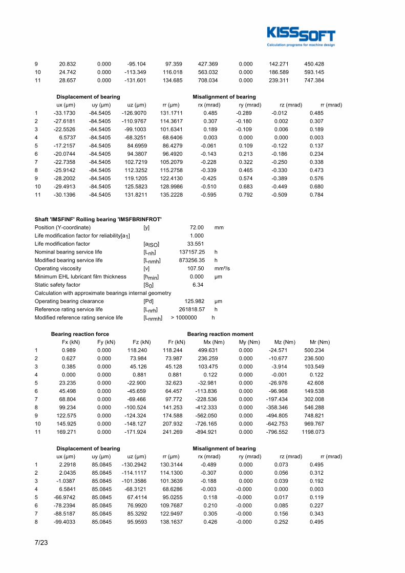
7/23
9 20.832 0.000 -95.104 97.359 427.369 0.000 142.271 450.42810 24.742 0.000 -113.349 116.018 563.032 0.000 186.589 593.14511 28.657 0.000 -131.601 134.685 708.034 0.000 239.311 747.384
Displacement of bearing Misalignment of bearing ux (µm) uy (µm) uz (µm) rr (µm) rx (mrad) ry (mrad) rz (mrad) rr (mrad)1 -33.1730 -84.5405 -126.9070 131.1711 0.485 -0.289 -0.012 0.4852 -27.6181 -84.5405 -110.9767 114.3617 0.307 -0.180 0.002 0.3073 -22.5526 -84.5405 -99.1003 101.6341 0.189 -0.109 0.006 0.1894 6.5737 -84.5405 -68.3251 68.6406 0.003 0.000 0.000 0.0035 -17.2157 -84.5405 84.6959 86.4279 -0.061 0.109 -0.122 0.1376 -20.0744 -84.5405 94.3807 96.4920 -0.143 0.213 -0.186 0.2347 -22.7358 -84.5405 102.7219 105.2079 -0.228 0.322 -0.250 0.3388 -25.9142 -84.5405 112.3252 115.2758 -0.339 0.465 -0.330 0.4739 -28.2002 -84.5405 119.1205 122.4130 -0.425 0.574 -0.389 0.57610 -29.4913 -84.5405 125.5823 128.9986 -0.510 0.683 -0.449 0.68011 -30.1396 -84.5405 131.8211 135.2228 -0.595 0.792 -0.509 0.784
Shaft 'IMSFINF' Rolling bearing 'IMSFBRINFROT'Position (Y-coordinate) [y] 72.00 mmLife modification factor for reliability[a1] 1.000Life modification factor [aISO] 33.551Nominal bearing service life [Lnh] 137157.25 hModified bearing service life [Lnmh] 873256.35 hOperating viscosity [ν] 107.50 mm²/sMinimum EHL lubricant film thickness [hmin] 0.000 µmStatic safety factor [S0] 6.34Calculation with approximate bearings internal geometryOperating bearing clearance [Pd] 125.982 µmReference rating service life [Lnrh] 261818.57 hModified reference rating service life [Lnrmh] > 1000000 h
Bearing reaction force Bearing reaction moment Fx (kN) Fy (kN) Fz (kN) Fr (kN) Mx (Nm) My (Nm) Mz (Nm) Mr (Nm)1 0.989 0.000 118.240 118.244 499.631 0.000 -24.571 500.2342 0.627 0.000 73.984 73.987 236.259 0.000 -10.677 236.5003 0.385 0.000 45.126 45.128 103.475 0.000 -3.914 103.5494 0.000 0.000 0.881 0.881 0.122 0.000 -0.001 0.1225 23.235 0.000 -22.900 32.623 -32.981 0.000 -26.976 42.6086 45.498 0.000 -45.659 64.457 -113.836 0.000 -96.968 149.5387 68.804 0.000 -69.466 97.772 -228.536 0.000 -197.434 302.0088 99.234 0.000 -100.524 141.253 -412.333 0.000 -358.346 546.2889 122.575 0.000 -124.324 174.588 -562.050 0.000 -494.805 748.82110 145.925 0.000 -148.127 207.932 -726.165 0.000 -642.753 969.76711 169.271 0.000 -171.924 241.269 -894.921 0.000 -796.552 1198.073
Displacement of bearing Misalignment of bearing ux (µm) uy (µm) uz (µm) rr (µm) rx (mrad) ry (mrad) rz (mrad) rr (mrad)1 2.2918 85.0845 -130.2942 130.3144 -0.489 0.000 0.073 0.4952 2.0435 85.0845 -114.1117 114.1300 -0.307 0.000 0.056 0.3123 -1.0387 85.0845 -101.3586 101.3639 -0.188 0.000 0.039 0.1924 6.5841 85.0845 -68.3121 68.6286 -0.003 -0.000 0.000 0.0035 -66.9742 85.0845 67.4114 95.0255 0.118 -0.000 0.017 0.1196 -78.2394 85.0845 76.9920 109.7687 0.210 -0.000 0.085 0.2277 -88.5187 85.0845 85.3292 122.9497 0.305 -0.000 0.156 0.3438 -99.4033 85.0845 95.9593 138.1637 0.426 -0.000 0.252 0.495

8/23
9 -106.2748 85.0845 104.2839 148.8941 0.518 -0.000 0.327 0.61210 -112.7108 85.0845 112.3351 159.1317 0.609 -0.000 0.400 0.72911 -118.8059 85.0845 120.2234 169.0222 0.699 -0.000 0.473 0.845
(*) Note about roller bearings with an approximated bearing geometry:The internal geometry of these bearings has not been input in the database.The geometry is back-calculated as specified in ISO 281, from C and C0 (details in the manufacturer's catalog).For this reason, the geometry may be different from the actual geometry.This can lead to differences in the service life calculation and, more importantly, the roller bearing stiffness.
Damage (%) [Lreq] ( 175200.000)Bin no B1 B2 1 0.00 0.00 2 0.00 0.00 3 0.00 0.00 4 0.00 0.00 5 0.00 0.01 6 0.01 0.07 7 0.02 0.38 8 0.24 4.37 9 0.25 4.23 10 0.00 0.02 11 0.00 0.00----------------------------Σ 0.52 9.08
Utilization (%) [Lreq] ( 175200.000) B1 B248.17 48.69Note: Utilization = (Lreq/Lh)^(1/k)Ball bearing: k = 3, roller bearing: k = 10/3
B 1: IMSFBRINFGENB 2: IMSFBRINFROT

9/23
Figure: Deformation (bending etc.) (Arbitrary plane 126.4681308 121)
Nominal stresses, without taking into account stress concentrationsGEH(von Mises): sigV = ((sigB+sigZ,D)^2 + 3*(tauT+tauS)^2)^1/2SSH(Tresca): sigV = ((sigB-sigZ,D)^2 + 4*(tauT+tauS)^2)^1/2
Figure: Equivalent stress

10/23

11/23
Strength calculation as specified in the FKM Guideline (6th Edition, 2012)Summary
IMSFINF
Material 18CrNiMo7-6Material type Case-carburized steelMaterial treatment case-hardenedSurface treatment No
Calculation of service strength and static strengthS-N curve (Woehler line) according Miner elementary
Rolled steel, case-hardening steelOverload case F1 (chapter 2.4.2): Constant mean stressSafety number according Chapter 2.5 [jF] 1.35Safety number according Chapter 1.5 [jm] 1.85Safety number according Chapter 1.5 [jp] 1.40Safety number according Chapter 1.5 [jmt] 1.40Safety number according Chapter 1.5 [jpt] 1.00
Safety number according Chapter 1.5 [jG] 1.00Cross section Pos (Y co-ord) (mm)A-A 300.00 ShoulderB-B 123.00 Shoulder with relief grooveC-C 488.00 ShoulderD-D 119.00 Interference fitResults:Cross section Kfb KRs ALGmax SD SS SBA-A 1.85 0.88 0.60 2.25 5.59 7.89B-B 3.10 0.88 0.49 2.76 8.86 12.51C-C 1.66 0.88 0.43 3.14 5.45 7.69D-D 2.61 1.00 0.35 3.81 8.96 12.66
Nominal safety: 1.35 1.40 1.85
Abbreviations:Kfb: Notch factor bendingKRs: Surface factorALGmax: Highest utilizationSD: Safety endurance limitSS: Safety against yield pointSB: Safety against tensile stress
Service life and damage
System service life (h) [Hatt] 1000000.00
Damage to system (%) [D] 0.00
Utilization (%) [Smin/S]

12/23
Cross section Static EnduranceA-A 25.065 60.058B-B 15.798 48.953C-C 25.705 43.002D-D 15.617 35.450
Maximum utilization (%) [A] 60.058
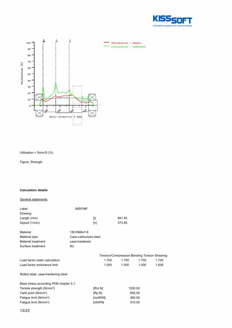
13/23
Utilization = Smin/S (%)
Figure: Strength
Calculation details
General statements
Label IMSFINFDrawingLength (mm) [l] 881.50Speed (1/min) [n] 373.85
Material 18CrNiMo7-6Material type Case-carburized steelMaterial treatment case-hardenedSurface treatment No
Tension/Compression Bending Torsion ShearingLoad factor static calculation 1.700 1.700 1.700 1.700Load factor endurance limit 1.000 1.000 1.000 1.000
Rolled steel, case-hardening steel
Base stress according FKM chapter 5.1:Tensile strength (N/mm²) [Rm,N] 1200.00Yield point (N/mm²) [Rp,N] 850.00Fatigue limit (N/mm²) [σzdWN] 480.00Fatigue limit (N/mm²) [σbWN] 510.00
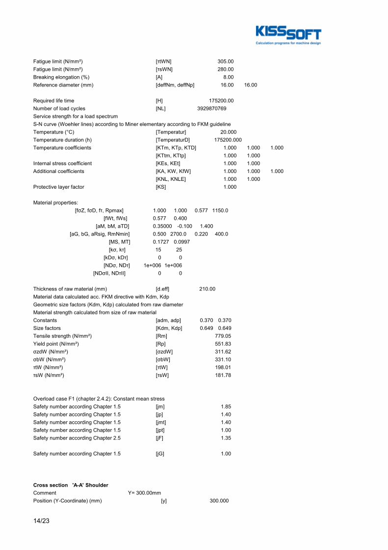
14/23
Fatigue limit (N/mm²) [τtWN] 305.00Fatigue limit (N/mm²) [τsWN] 280.00Breaking elongation (%) [A] 8.00Reference diameter (mm) [deffNm, deffNp] 16.00 16.00
Required life time [H] 175200.00Number of load cycles [NL] 3929870769Service strength for a load spectrumS-N curve (Woehler lines) according to Miner elementary according to FKM guidelineTemperature (°C) [Temperatur] 20.000Temperature duration (h) [TemperaturD] 175200.000Temperature coefficients [KTm, KTp, KTD] 1.000 1.000 1.000 [KTtm, KTtp] 1.000 1.000Internal stress coefficient [KEs, KEt] 1.000 1.000Additional coefficients [KA, KW, KfW] 1.000 1.000 1.000 [KNL, KNLE] 1.000 1.000Protective layer factor [KS] 1.000
Material properties: [fσZ, fσD, fτ, Rpmax] 1.000 1.000 0.577 1150.0 [fWt, fWs] 0.577 0.400 [aM, bM, aTD] 0.35000 -0.100 1.400 [aG, bG, aRsig, RmNmin] 0.500 2700.0 0.220 400.0 [MS, MT] 0.1727 0.0997 [kσ, kτ] 15 25 [kDσ, kDτ] 0 0 [NDσ, NDτ] 1e+006 1e+006 [NDσII, NDτII] 0 0
Thickness of raw material (mm) [d.eff] 210.00Material data calculated acc. FKM directive with Kdm, KdpGeometric size factors (Kdm, Kdp) calculated from raw diameterMaterial strength calculated from size of raw materialConstants [adm, adp] 0.370 0.370Size factors [Kdm, Kdp] 0.649 0.649Tensile strength (N/mm²) [Rm] 779.05Yield point (N/mm²) [Rp] 551.83σzdW (N/mm²) [σzdW] 311.62σbW (N/mm²) [σbW] 331.10τtW (N/mm²) [τtW] 198.01τsW (N/mm²) [τsW] 181.78
Overload case F1 (chapter 2.4.2): Constant mean stressSafety number according Chapter 1.5 [jm] 1.85Safety number according Chapter 1.5 [jp] 1.40Safety number according Chapter 1.5 [jmt] 1.40Safety number according Chapter 1.5 [jpt] 1.00Safety number according Chapter 2.5 [jF] 1.35
Safety number according Chapter 1.5 [jG] 1.00
Cross section 'A-A' ShoulderComment Y= 300.00mmPosition (Y-Coordinate) (mm) [y] 300.000
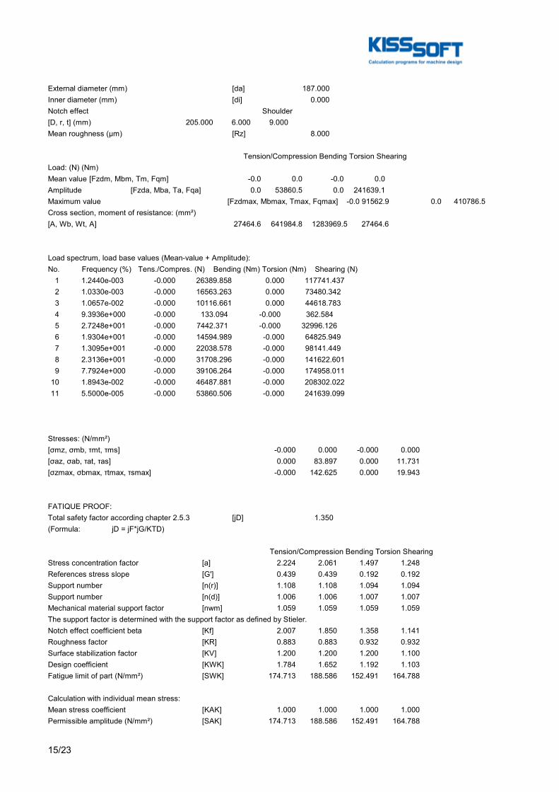
15/23
External diameter (mm) [da] 187.000Inner diameter (mm) [di] 0.000Notch effect Shoulder[D, r, t] (mm) 205.000 6.000 9.000Mean roughness (µm) [Rz] 8.000
Tension/Compression Bending Torsion ShearingLoad: (N) (Nm)Mean value [Fzdm, Mbm, Tm, Fqm] -0.0 0.0 -0.0 0.0Amplitude [Fzda, Mba, Ta, Fqa] 0.0 53860.5 0.0 241639.1Maximum value [Fzdmax, Mbmax, Tmax, Fqmax] -0.0 91562.9 0.0 410786.5Cross section, moment of resistance: (mm²)[A, Wb, Wt, A] 27464.6 641984.8 1283969.5 27464.6
Load spectrum, load base values (Mean-value + Amplitude):No. Frequency (%) Tens./Compres. (N) Bending (Nm) Torsion (Nm) Shearing (N) 1 1.2440e-003 -0.000 26389.858 0.000 117741.437 2 1.0330e-003 -0.000 16563.263 0.000 73480.342 3 1.0657e-002 -0.000 10116.661 0.000 44618.783 4 9.3936e+000 -0.000 133.094 -0.000 362.584 5 2.7248e+001 -0.000 7442.371 -0.000 32996.126 6 1.9304e+001 -0.000 14594.989 -0.000 64825.949 7 1.3095e+001 -0.000 22038.578 -0.000 98141.449 8 2.3136e+001 -0.000 31708.296 -0.000 141622.601 9 7.7924e+000 -0.000 39106.264 -0.000 174958.011 10 1.8943e-002 -0.000 46487.881 -0.000 208302.022 11 5.5000e-005 -0.000 53860.506 -0.000 241639.099
Stresses: (N/mm²)[σmz, σmb, τmt, τms] -0.000 0.000 -0.000 0.000[σaz, σab, τat, τas] 0.000 83.897 0.000 11.731[σzmax, σbmax, τtmax, τsmax] -0.000 142.625 0.000 19.943
FATIQUE PROOF:Total safety factor according chapter 2.5.3 [jD] 1.350(Formula: jD = jF*jG/KTD)
Tension/Compression Bending Torsion ShearingStress concentration factor [a] 2.224 2.061 1.497 1.248References stress slope [G'] 0.439 0.439 0.192 0.192Support number [n(r)] 1.108 1.108 1.094 1.094Support number [n(d)] 1.006 1.006 1.007 1.007Mechanical material support factor [nwm] 1.059 1.059 1.059 1.059The support factor is determined with the support factor as defined by Stieler.Notch effect coefficient beta [Kf] 2.007 1.850 1.358 1.141Roughness factor [KR] 0.883 0.883 0.932 0.932Surface stabilization factor [KV] 1.200 1.200 1.200 1.100Design coefficient [KWK] 1.784 1.652 1.192 1.103Fatigue limit of part (N/mm²) [SWK] 174.713 188.586 152.491 164.788
Calculation with individual mean stress:Mean stress coefficient [KAK] 1.000 1.000 1.000 1.000Permissible amplitude (N/mm²) [SAK] 174.713 188.586 152.491 164.788

16/23
Effective Miner sum [DM] 0.3 0.33 0.3 0.3Coefficient service strength [KBK] 1.000 1.000 1.026 1.038Permissible amplitude (N/mm²) [SBK] 174.713 188.586 156.484 171.061Rate of utilization [aBK] 0.000 0.601 0.000 0.093
Calculation of the combined stress types:Rate of utilization for the combined load componentsa)For outer surface (shear stress = 0) Equivalent mean stress (N/mm²) [SmV_1] 0.000 Rate of utilization [aBKv_1] 0.601b) For neutral line (Bending stress = 0) Equivalent mean stress (N/mm²) [SmV_2] 0.000 Rate of utilization [aBKv_2] 0.093
Highest utilization [aBKmax] 0.601Safety endurance limit assessment [S.Dauer] 2.248Required safety [jD] 1.350Result (%) [S/jD] 166.5
STATIC STRENGTH ASSESSMENT:Total safety factor according chapter 1.5.3 [jges] 1.400(Formula: jges = jG*Max(jm/KTm*Rp/Rm, jp/KTp, jmt/KTtm*Rp/Rm, jpt/KTtp))
Tension/Compression Bending Torsion ShearingPlastic notch factor [Kpb, Kpt] 1.700 1.330Plastic support number [npl] 1.0000 1.4436 1.3300 1.0000Strength of part (N/mm²) [SSK] 551.83 796.62 423.73 318.60Rate of utilization [aSK] 0.000 0.251 0.000 0.088
Rate of utilization for the combined load components:a)For outer surface (shear stress = 0) Equivalent stress (N/mm²) [SvBn] 142.625 Rate of utilization [aSKvBn] 0.251b) For neutral line (Bending stress = 0) Equivalent stress (N/mm²) [SvQn] 34.542 Rate of utilization [aSKvQn] 0.088
Highest utilization [aSKmax] 0.251
Safety for fracture and yield stresses:Safety against fracture [S.Rm] 7.885Required safety [jm/Ktm] 1.850Result (%) [S/jm] 426.2
Safety against yield point [S.Rp] 5.585Required safety [jp/KTp] 1.400Result (%) [S/jp] 399.0
Cross section 'B-B' Shoulder with relief grooveComment Y= 123.00mmPosition (Y-Coordinate) (mm) [y] 123.000External diameter (mm) [da] 140.000Inner diameter (mm) [di] 0.000Notch effect Shoulder with relief groove
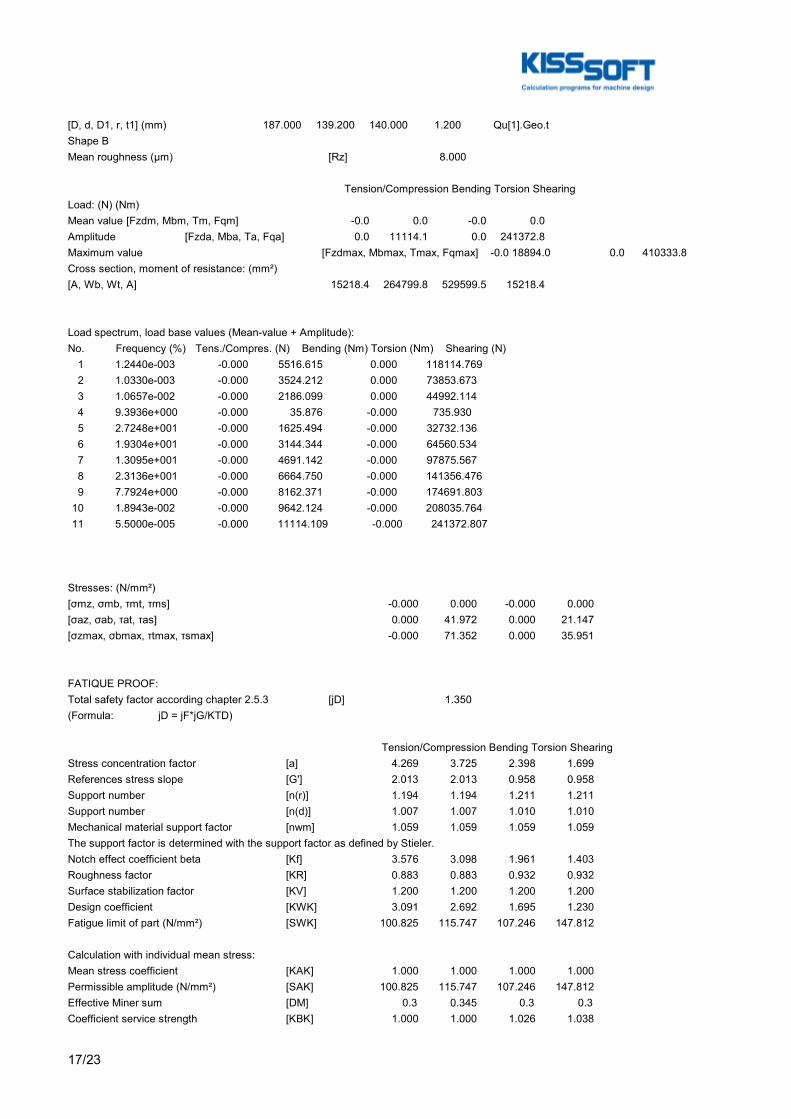
17/23
[D, d, D1, r, t1] (mm) 187.000 139.200 140.000 1.200 Qu[1].Geo.tShape BMean roughness (µm) [Rz] 8.000
Tension/Compression Bending Torsion ShearingLoad: (N) (Nm)Mean value [Fzdm, Mbm, Tm, Fqm] -0.0 0.0 -0.0 0.0Amplitude [Fzda, Mba, Ta, Fqa] 0.0 11114.1 0.0 241372.8Maximum value [Fzdmax, Mbmax, Tmax, Fqmax] -0.0 18894.0 0.0 410333.8Cross section, moment of resistance: (mm²)[A, Wb, Wt, A] 15218.4 264799.8 529599.5 15218.4
Load spectrum, load base values (Mean-value + Amplitude):No. Frequency (%) Tens./Compres. (N) Bending (Nm) Torsion (Nm) Shearing (N) 1 1.2440e-003 -0.000 5516.615 0.000 118114.769 2 1.0330e-003 -0.000 3524.212 0.000 73853.673 3 1.0657e-002 -0.000 2186.099 0.000 44992.114 4 9.3936e+000 -0.000 35.876 -0.000 735.930 5 2.7248e+001 -0.000 1625.494 -0.000 32732.136 6 1.9304e+001 -0.000 3144.344 -0.000 64560.534 7 1.3095e+001 -0.000 4691.142 -0.000 97875.567 8 2.3136e+001 -0.000 6664.750 -0.000 141356.476 9 7.7924e+000 -0.000 8162.371 -0.000 174691.803 10 1.8943e-002 -0.000 9642.124 -0.000 208035.764 11 5.5000e-005 -0.000 11114.109 -0.000 241372.807
Stresses: (N/mm²)[σmz, σmb, τmt, τms] -0.000 0.000 -0.000 0.000[σaz, σab, τat, τas] 0.000 41.972 0.000 21.147[σzmax, σbmax, τtmax, τsmax] -0.000 71.352 0.000 35.951
FATIQUE PROOF:Total safety factor according chapter 2.5.3 [jD] 1.350(Formula: jD = jF*jG/KTD)
Tension/Compression Bending Torsion ShearingStress concentration factor [a] 4.269 3.725 2.398 1.699References stress slope [G'] 2.013 2.013 0.958 0.958Support number [n(r)] 1.194 1.194 1.211 1.211Support number [n(d)] 1.007 1.007 1.010 1.010Mechanical material support factor [nwm] 1.059 1.059 1.059 1.059The support factor is determined with the support factor as defined by Stieler.Notch effect coefficient beta [Kf] 3.576 3.098 1.961 1.403Roughness factor [KR] 0.883 0.883 0.932 0.932Surface stabilization factor [KV] 1.200 1.200 1.200 1.200Design coefficient [KWK] 3.091 2.692 1.695 1.230Fatigue limit of part (N/mm²) [SWK] 100.825 115.747 107.246 147.812
Calculation with individual mean stress:Mean stress coefficient [KAK] 1.000 1.000 1.000 1.000Permissible amplitude (N/mm²) [SAK] 100.825 115.747 107.246 147.812Effective Miner sum [DM] 0.3 0.345 0.3 0.3Coefficient service strength [KBK] 1.000 1.000 1.026 1.038
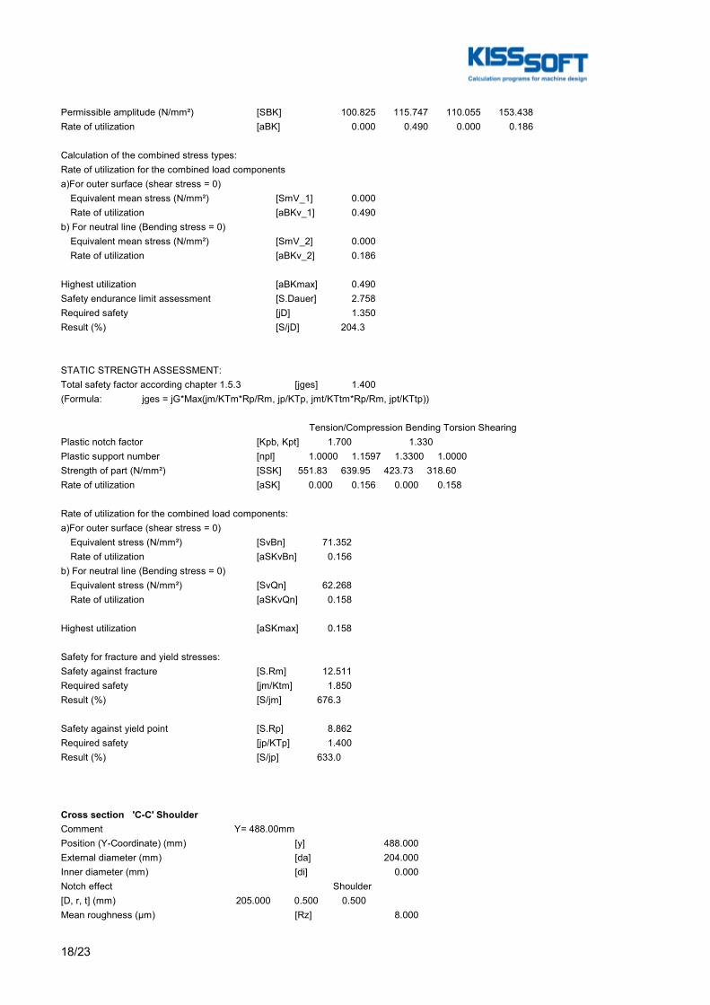
18/23
Permissible amplitude (N/mm²) [SBK] 100.825 115.747 110.055 153.438Rate of utilization [aBK] 0.000 0.490 0.000 0.186
Calculation of the combined stress types:Rate of utilization for the combined load componentsa)For outer surface (shear stress = 0) Equivalent mean stress (N/mm²) [SmV_1] 0.000 Rate of utilization [aBKv_1] 0.490b) For neutral line (Bending stress = 0) Equivalent mean stress (N/mm²) [SmV_2] 0.000 Rate of utilization [aBKv_2] 0.186
Highest utilization [aBKmax] 0.490Safety endurance limit assessment [S.Dauer] 2.758Required safety [jD] 1.350Result (%) [S/jD] 204.3
STATIC STRENGTH ASSESSMENT:Total safety factor according chapter 1.5.3 [jges] 1.400(Formula: jges = jG*Max(jm/KTm*Rp/Rm, jp/KTp, jmt/KTtm*Rp/Rm, jpt/KTtp))
Tension/Compression Bending Torsion ShearingPlastic notch factor [Kpb, Kpt] 1.700 1.330Plastic support number [npl] 1.0000 1.1597 1.3300 1.0000Strength of part (N/mm²) [SSK] 551.83 639.95 423.73 318.60Rate of utilization [aSK] 0.000 0.156 0.000 0.158
Rate of utilization for the combined load components:a)For outer surface (shear stress = 0) Equivalent stress (N/mm²) [SvBn] 71.352 Rate of utilization [aSKvBn] 0.156b) For neutral line (Bending stress = 0) Equivalent stress (N/mm²) [SvQn] 62.268 Rate of utilization [aSKvQn] 0.158
Highest utilization [aSKmax] 0.158
Safety for fracture and yield stresses:Safety against fracture [S.Rm] 12.511Required safety [jm/Ktm] 1.850Result (%) [S/jm] 676.3
Safety against yield point [S.Rp] 8.862Required safety [jp/KTp] 1.400Result (%) [S/jp] 633.0
Cross section 'C-C' ShoulderComment Y= 488.00mmPosition (Y-Coordinate) (mm) [y] 488.000External diameter (mm) [da] 204.000Inner diameter (mm) [di] 0.000Notch effect Shoulder[D, r, t] (mm) 205.000 0.500 0.500Mean roughness (µm) [Rz] 8.000
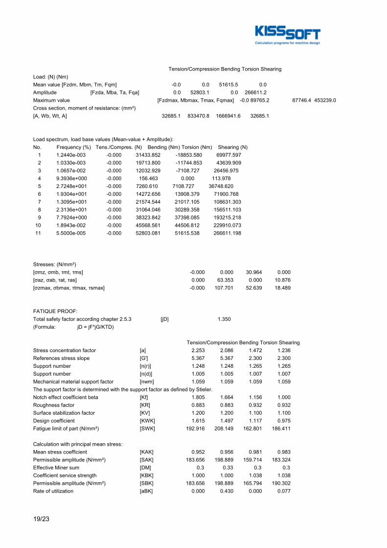
19/23
Tension/Compression Bending Torsion ShearingLoad: (N) (Nm)Mean value [Fzdm, Mbm, Tm, Fqm] -0.0 0.0 51615.5 0.0Amplitude [Fzda, Mba, Ta, Fqa] 0.0 52803.1 0.0 266611.2Maximum value [Fzdmax, Mbmax, Tmax, Fqmax] -0.0 89765.2 87746.4 453239.0Cross section, moment of resistance: (mm²)[A, Wb, Wt, A] 32685.1 833470.8 1666941.6 32685.1
Load spectrum, load base values (Mean-value + Amplitude):No. Frequency (%) Tens./Compres. (N) Bending (Nm) Torsion (Nm) Shearing (N) 1 1.2440e-003 -0.000 31433.852 -18853.580 69977.597 2 1.0330e-003 -0.000 19713.800 -11744.853 43639.909 3 1.0657e-002 -0.000 12032.929 -7108.727 26456.975 4 9.3936e+000 -0.000 156.463 0.000 113.978 5 2.7248e+001 -0.000 7260.610 7108.727 36748.620 6 1.9304e+001 -0.000 14272.656 13908.379 71900.768 7 1.3095e+001 -0.000 21574.544 21017.105 108631.303 8 2.3136e+001 -0.000 31064.046 30289.358 156511.103 9 7.7924e+000 -0.000 38323.842 37398.085 193215.218 10 1.8943e-002 -0.000 45568.561 44506.812 229910.073 11 5.5000e-005 -0.000 52803.081 51615.538 266611.198
Stresses: (N/mm²)[σmz, σmb, τmt, τms] -0.000 0.000 30.964 0.000[σaz, σab, τat, τas] 0.000 63.353 0.000 10.876[σzmax, σbmax, τtmax, τsmax] -0.000 107.701 52.639 18.489
FATIQUE PROOF:Total safety factor according chapter 2.5.3 [jD] 1.350(Formula: jD = jF*jG/KTD)
Tension/Compression Bending Torsion ShearingStress concentration factor [a] 2.253 2.086 1.472 1.236References stress slope [G'] 5.367 5.367 2.300 2.300Support number [n(r)] 1.248 1.248 1.265 1.265Support number [n(d)] 1.005 1.005 1.007 1.007Mechanical material support factor [nwm] 1.059 1.059 1.059 1.059The support factor is determined with the support factor as defined by Stieler.Notch effect coefficient beta [Kf] 1.805 1.664 1.156 1.000Roughness factor [KR] 0.883 0.883 0.932 0.932Surface stabilization factor [KV] 1.200 1.200 1.100 1.100Design coefficient [KWK] 1.615 1.497 1.117 0.975Fatigue limit of part (N/mm²) [SWK] 192.916 208.149 162.801 186.411
Calculation with principal mean stress:Mean stress coefficient [KAK] 0.952 0.956 0.981 0.983Permissible amplitude (N/mm²) [SAK] 183.656 198.889 159.714 183.324Effective Miner sum [DM] 0.3 0.33 0.3 0.3Coefficient service strength [KBK] 1.000 1.000 1.038 1.038Permissible amplitude (N/mm²) [SBK] 183.656 198.889 165.794 190.302Rate of utilization [aBK] 0.000 0.430 0.000 0.077
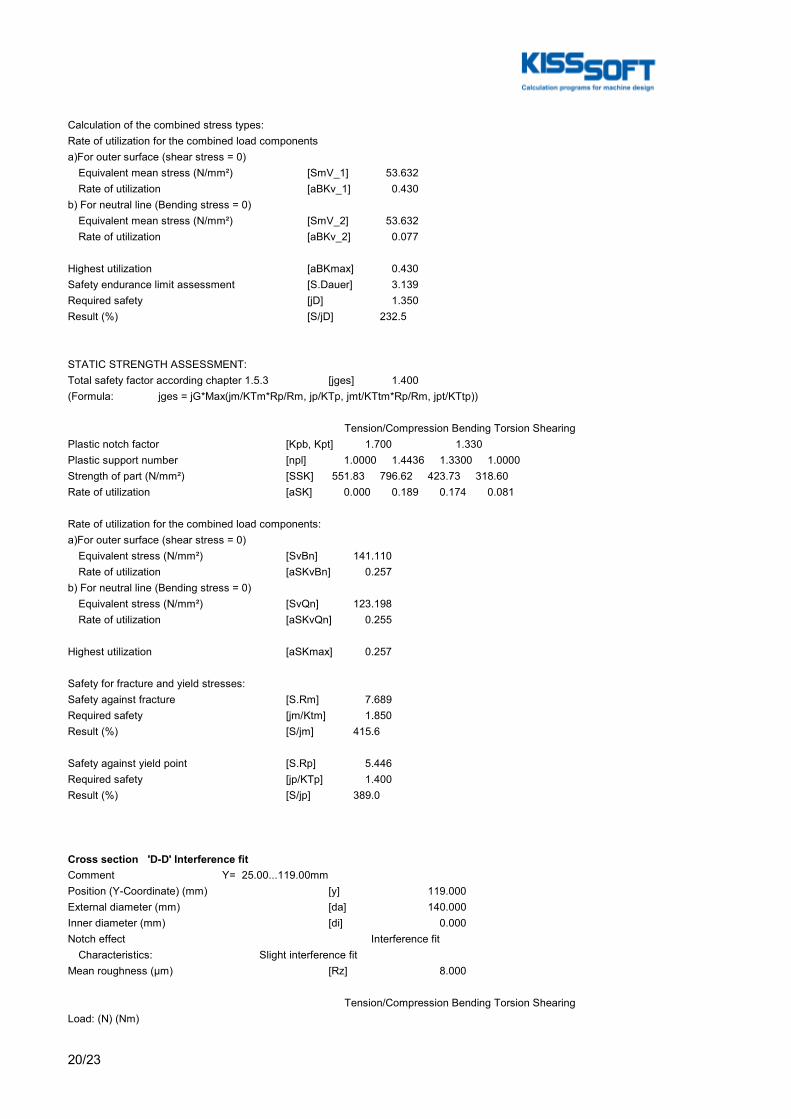
20/23
Calculation of the combined stress types:Rate of utilization for the combined load componentsa)For outer surface (shear stress = 0) Equivalent mean stress (N/mm²) [SmV_1] 53.632 Rate of utilization [aBKv_1] 0.430b) For neutral line (Bending stress = 0) Equivalent mean stress (N/mm²) [SmV_2] 53.632 Rate of utilization [aBKv_2] 0.077
Highest utilization [aBKmax] 0.430Safety endurance limit assessment [S.Dauer] 3.139Required safety [jD] 1.350Result (%) [S/jD] 232.5
STATIC STRENGTH ASSESSMENT:Total safety factor according chapter 1.5.3 [jges] 1.400(Formula: jges = jG*Max(jm/KTm*Rp/Rm, jp/KTp, jmt/KTtm*Rp/Rm, jpt/KTtp))
Tension/Compression Bending Torsion ShearingPlastic notch factor [Kpb, Kpt] 1.700 1.330Plastic support number [npl] 1.0000 1.4436 1.3300 1.0000Strength of part (N/mm²) [SSK] 551.83 796.62 423.73 318.60Rate of utilization [aSK] 0.000 0.189 0.174 0.081
Rate of utilization for the combined load components:a)For outer surface (shear stress = 0) Equivalent stress (N/mm²) [SvBn] 141.110 Rate of utilization [aSKvBn] 0.257b) For neutral line (Bending stress = 0) Equivalent stress (N/mm²) [SvQn] 123.198 Rate of utilization [aSKvQn] 0.255
Highest utilization [aSKmax] 0.257
Safety for fracture and yield stresses:Safety against fracture [S.Rm] 7.689Required safety [jm/Ktm] 1.850Result (%) [S/jm] 415.6
Safety against yield point [S.Rp] 5.446Required safety [jp/KTp] 1.400Result (%) [S/jp] 389.0
Cross section 'D-D' Interference fitComment Y= 25.00...119.00mmPosition (Y-Coordinate) (mm) [y] 119.000External diameter (mm) [da] 140.000Inner diameter (mm) [di] 0.000Notch effect Interference fit Characteristics: Slight interference fitMean roughness (µm) [Rz] 8.000
Tension/Compression Bending Torsion ShearingLoad: (N) (Nm)
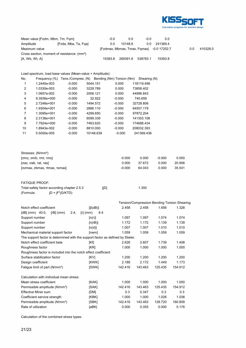
21/23
Mean value [Fzdm, Mbm, Tm, Fqm] -0.0 0.0 -0.0 0.0Amplitude [Fzda, Mba, Ta, Fqa] 0.0 10148.6 0.0 241369.4Maximum value [Fzdmax, Mbmax, Tmax, Fqmax] -0.0 17252.7 0.0 410328.0Cross section, moment of resistance: (mm²)[A, Wb, Wt, A] 15393.8 269391.6 538783.1 15393.8
Load spectrum, load base values (Mean-value + Amplitude):No. Frequency (%) Tens./Compres. (N) Bending (Nm) Torsion (Nm) Shearing (N) 1 1.2440e-003 -0.000 5044.151 0.000 118119.498 2 1.0330e-003 -0.000 3228.789 0.000 73858.402 3 1.0657e-002 -0.000 2006.121 0.000 44996.843 4 9.3936e+000 -0.000 32.922 -0.000 740.659 5 2.7248e+001 -0.000 1494.572 -0.000 32728.806 6 1.9304e+001 -0.000 2886.110 -0.000 64557.179 7 1.3095e+001 -0.000 4299.650 -0.000 97872.204 8 2.3136e+001 -0.000 6099.339 -0.000 141353.108 9 7.7924e+000 -0.000 7463.620 -0.000 174688.434 10 1.8943e-002 -0.000 8810.000 -0.000 208032.393 11 5.5000e-005 -0.000 10148.639 -0.000 241369.436
Stresses: (N/mm²)[σmz, σmb, τmt, τms] -0.000 0.000 -0.000 0.000[σaz, σab, τat, τas] 0.000 37.672 0.000 20.906[σzmax, σbmax, τtmax, τsmax] -0.000 64.043 0.000 35.541
FATIQUE PROOF:Total safety factor according chapter 2.5.3 [jD] 1.350(Formula: jD = jF*jG/KTD)
Tension/Compression Bending Torsion ShearingNotch effect coefficient [β(dB)] 2.458 2.458 1.656 1.328[dB] (mm) 40.0, [rB] (mm) 2.4, [r] (mm) 8.4Support number [n(r)] 1.097 1.097 1.074 1.074Support number [n(rB)] 1.172 1.172 1.139 1.139Support number [n(d)] 1.007 1.007 1.010 1.010Mechanical material support factor [nwm] 1.059 1.059 1.059 1.059The support factor is determined with the support factor as defined by Stieler.Notch effect coefficient beta [Kf] 2.626 2.607 1.739 1.408Roughness factor [KR] 1.000 1.000 1.000 1.000Roughness factor is included into the notch effect coefficientSurface stabilization factor [KV] 1.200 1.200 1.200 1.200Design coefficient [KWK] 2.188 2.172 1.449 1.173Fatigue limit of part (N/mm²) [SWK] 142.416 143.463 125.435 154.912
Calculation with individual mean stress:Mean stress coefficient [KAK] 1.000 1.000 1.000 1.000Permissible amplitude (N/mm²) [SAK] 142.416 143.463 125.435 154.912Effective Miner sum [DM] 0.3 0.347 0.3 0.3Coefficient service strength [KBK] 1.000 1.000 1.026 1.038Permissible amplitude (N/mm²) [SBK] 142.416 143.463 128.720 160.809Rate of utilization [aBK] 0.000 0.355 0.000 0.176
Calculation of the combined stress types:
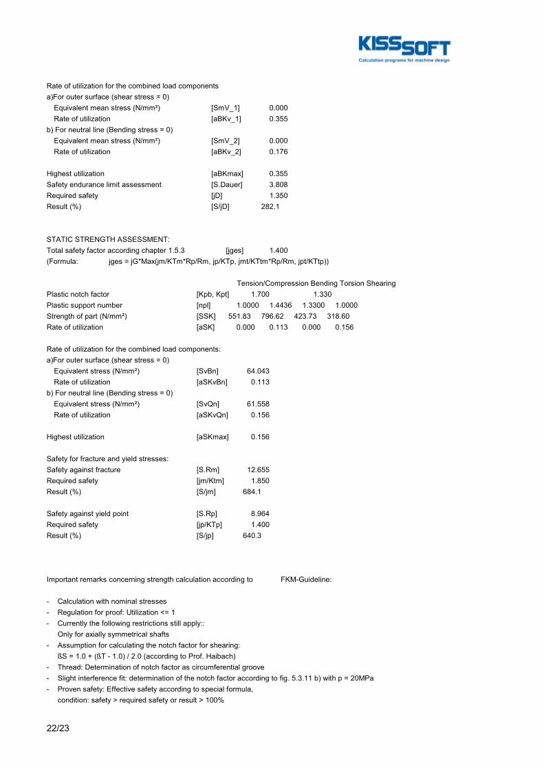
22/23
Rate of utilization for the combined load componentsa)For outer surface (shear stress = 0) Equivalent mean stress (N/mm²) [SmV_1] 0.000 Rate of utilization [aBKv_1] 0.355b) For neutral line (Bending stress = 0) Equivalent mean stress (N/mm²) [SmV_2] 0.000 Rate of utilization [aBKv_2] 0.176
Highest utilization [aBKmax] 0.355Safety endurance limit assessment [S.Dauer] 3.808Required safety [jD] 1.350Result (%) [S/jD] 282.1
STATIC STRENGTH ASSESSMENT:Total safety factor according chapter 1.5.3 [jges] 1.400(Formula: jges = jG*Max(jm/KTm*Rp/Rm, jp/KTp, jmt/KTtm*Rp/Rm, jpt/KTtp))
Tension/Compression Bending Torsion ShearingPlastic notch factor [Kpb, Kpt] 1.700 1.330Plastic support number [npl] 1.0000 1.4436 1.3300 1.0000Strength of part (N/mm²) [SSK] 551.83 796.62 423.73 318.60Rate of utilization [aSK] 0.000 0.113 0.000 0.156
Rate of utilization for the combined load components:a)For outer surface (shear stress = 0) Equivalent stress (N/mm²) [SvBn] 64.043 Rate of utilization [aSKvBn] 0.113b) For neutral line (Bending stress = 0) Equivalent stress (N/mm²) [SvQn] 61.558 Rate of utilization [aSKvQn] 0.156
Highest utilization [aSKmax] 0.156
Safety for fracture and yield stresses:Safety against fracture [S.Rm] 12.655Required safety [jm/Ktm] 1.850Result (%) [S/jm] 684.1
Safety against yield point [S.Rp] 8.964Required safety [jp/KTp] 1.400Result (%) [S/jp] 640.3
Important remarks concerning strength calculation according to FKM-Guideline:
- Calculation with nominal stresses- Regulation for proof: Utilization <= 1- Currently the following restrictions still apply:: Only for axially symmetrical shafts- Assumption for calculating the notch factor for shearing: ßS = 1.0 + (ßT - 1.0) / 2.0 (according to Prof. Haibach)- Thread: Determination of notch factor as circumferential groove- Slight interference fit: determination of the notch factor according to fig. 5.3.11 b) with p = 20MPa- Proven safety: Effective safety according to special formula, condition: safety > required safety or result > 100%

23/23
End of Report lines: 1009

A. KISSsoft Reports
256

A.2. KISSsoft Reports - Shaft calculation
A.2.5 KISSsoft Report - High speed shaft (Output)
257

A. KISSsoft Reports
258
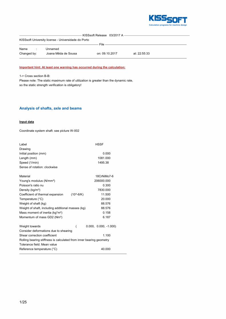
1/25
KISSsoft Release 03/2017 A KISSsoft University license - Universidade do Porto File Name : UnnamedChanged by: Joana Mêda de Sousa on: 09.10.2017 at: 22:55:33
Important hint: At least one warning has occurred during the calculation:
1-> Cross section B-B:Please note: The static maximum rate of utilization is greater than the dynamic rate,so the static strength verification is obligatory!
Analysis of shafts, axle and beams
Input data
Coordinate system shaft: see picture W-002
Label HSSFDrawingInitial position (mm) 0.000Length (mm) 1081.000Speed (1/min) 1495.38Sense of rotation: clockwise
Material 18CrNiMo7-6Young's modulus (N/mm²) 206000.000Poisson's ratio nu 0.300Density (kg/m³) 7830.000Coefficient of thermal expansion (10^-6/K) 11.500Temperature (°C) 20.000Weight of shaft (kg) 88.576Weight of shaft, including additional masses (kg) 88.576Mass moment of inertia (kg*m²) 0.158Momentum of mass GD2 (Nm²) 6.187
Weight towards ( 0.000, 0.000, -1.000)Consider deformations due to shearingShear correction coefficient 1.100Rolling bearing stiffness is calculated from inner bearing geometryTolerance field: Mean valueReference temperature (°C) 40.000

2/25
Figure: Load applications
Shaft definition (HSSF)
Outer contour
Cylinder (Cylinder) 0.000mm ... 64.000mm Diameter (mm) [d] 100.0000Length (mm) [l] 64.0000Surface roughness (µm) [Rz] 8.0000
Chamfer left (Chamfer left) l=8.00 (mm), alpha=45.00 (°)
Square groove (Square groove) b=3.00 (mm), t=2.00 (mm), r=0.50 (mm), Rz=8.0, Turned (Ra=3.2μm/125μin)
Relief groove right (Relief groove right) r=1.20 (mm), t=0.40 (mm), l=4.00 (mm), Rz=8.0, Turned (Ra=3.2μm/125μin) Form F (DIN 509), Series 1, with the usual stressing
Cylinder (Cylinder) 64.000mm ... 480.000mm Diameter (mm) [d] 125.0000Length (mm) [l] 416.0000Surface roughness (µm) [Rz] 8.0000
Chamfer left (Chamfer left) l=5.00 (mm), alpha=45.00 (°)
Radius right (Radius right)

3/25
r=1.00 (mm), Rz=8.0, Turned (Ra=3.2μm/125μin)
Cylinder (Cylinder) 480.000mm ... 607.000mm Diameter (mm) [d] 134.0000Length (mm) [l] 127.0000Surface roughness (µm) [Rz] 8.0000
Cylinder (Cylinder) 607.000mm ... 711.000mm Diameter (mm) [d] 125.0000Length (mm) [l] 104.0000Surface roughness (µm) [Rz] 8.0000
Radius left (Radius left) r=1.00 (mm), Rz=8.0, Turned (Ra=3.2μm/125μin)
Chamfer right (Chamfer right) l=5.00 (mm), alpha=45.00 (°)
Cylinder (Cylinder) 711.000mm ... 901.000mm Diameter (mm) [d] 100.0000Length (mm) [l] 190.0000Surface roughness (µm) [Rz] 8.0000
Relief groove left (Relief groove left) r=1.20 (mm), t=0.40 (mm), l=4.00 (mm), Rz=8.0, Turned (Ra=3.2μm/125μin) Form F (DIN 509), Series 1, with the usual stressing
Chamfer right (Chamfer right) l=2.00 (mm), alpha=45.00 (°)
Cylinder (Cylinder) 901.000mm ... 1081.000mm Diameter (mm) [d] 90.0000Length (mm) [l] 180.0000Surface roughness (µm) [Rz] 8.0000
Key way (Key way) 936.000mm ... 1046.000mm l=110.00 (mm), Rz=8.0, Turned (Ra=3.2μm/125μin)
Forces
Type of force element CouplingLabel in the model HSC(HSOUTPUT)Position on shaft (mm) [ylocal] 1060.0000Position in global system (mm) [yglobal] 1060.0000Effective diameter (mm) 90.0000Radial force factor (-) 0.0000Direction of the radial force (°) 0.0000Axial force factor (-) 0.0000Length of load application (mm) 10.0000Power (kW) 2420.0081Torque (Nm) -15453.8000Axial force (load spectrum) (N) 0.0000 / 0.0000 / 0.0000

4/25
Shearing force X (load spectrum) (N) 0.0000 / 0.0000 / 0.0000Shearing force Z (Load spectrum) (N) 0.0000 / 0.0000 / 0.0000Mass (kg) 0.0000Mass moment of inertia Jp (kg*m²) 0.0000Mass moment of inertia Jxx (kg*m²) 0.0000Mass moment of inertia Jzz (kg*m²) 0.0000Eccentricity (mm) 0.0000Load spectrum, driving (output)
No. Frequency (%) Speed (1/min) Power (kW) Torque (Nm) 1 1.2440e-003 1495.385 1476.205 9426.818 2 1.0330e-003 1495.385 919.603 5872.444 3 1.0657e-002 1495.385 556.602 3554.374 4 9.3936e+000 1495.385 -0.000 -0.000 5 2.7248e+001 1495.385 -556.602 -3554.374 6 1.9304e+001 1495.385 -1089.004 -6954.210 7 1.3095e+001 1495.385 -1645.605 -10508.584 8 2.3136e+001 1495.385 -2371.608 -15144.724 9 7.7924e+000 1495.385 -2928.210 -18699.098 10 1.8943e-002 1495.385 -3484.812 -22253.472 11 5.5000e-005 1495.385 -4041.413 -25807.846
Type of force element Cylindrical gearLabel in the model HSG(IMHSINFPGCT)Position on shaft (mm) [ylocal] 543.5000Position in global system (mm) [yglobal] 543.5000Operating pitch diameter (mm) 138.6000Helix angle (°) 25.1077 Double helical gearing, left-rightWorking pressure angle at normal section (°) 20.6227Position of contact (°) -67.9915Length of load application (mm) 127.0000Power (kW) 1210.0004Torque (Nm) 7726.8770Axial force (load spectrum) (N) 0.0000 / 0.0000 / 0.0000Shearing force X (load spectrum) (N) 52465.3148 / 32683.3108 / 19782.0039Shearing force Z (Load spectrum) (N) 51694.7163 / 32203.2659 / 19491.4504Bending moment X (Load spectrum) (Nm) 0.0000 / 0.0000 / 0.0000Bending moment Z (Load spectrum) (Nm) 0.0000 / 0.0000 / 0.0000Load spectrum, driven (input)
No. Frequency (%) Speed (1/min) Power (kW) Torque (Nm) 1 1.2440e-003 1495.385 -738.100 -4713.395 2 1.0330e-003 1495.385 -459.800 -2936.213 3 1.0657e-002 1495.385 -278.300 -1777.182 4 9.3936e+000 1495.385 0.000 0.000 5 2.7248e+001 1495.385 278.300 1777.182 6 1.9304e+001 1495.385 544.500 3477.095 7 1.3095e+001 1495.385 822.800 5254.276 8 2.3136e+001 1495.385 1185.800 7572.339 9 7.7924e+000 1495.385 1464.101 9349.521 10 1.8943e-002 1495.385 1742.401 11126.703 11 5.5000e-005 1495.385 2020.701 12903.885
Type of force element Cylindrical gearLabel in the model HSG(IMHSSUPPGCT)Position on shaft (mm) [ylocal] 543.5000Position in global system (mm) [yglobal] 543.5000

5/25
Operating pitch diameter (mm) 138.6000Helix angle (°) 25.1077 Double helical gearing, left-rightWorking pressure angle at normal section (°) 20.6227Position of contact (°) 67.9915Length of load application (mm) 127.0000Power (kW) 1210.0004Torque (Nm) 7726.8770Axial force (load spectrum) (N) 0.0000 / 0.0000 / 0.0000Shearing force X (load spectrum) (N) -73650.7723 / -45880.8090 / -27769.9633Shearing force Z (Load spectrum) (N) -718.8058 / -447.7807 / -271.0251Bending moment X (Load spectrum) (Nm) 0.0000 / 0.0000 / 0.0000Bending moment Z (Load spectrum) (Nm) 0.0000 / 0.0000 / 0.0000Load spectrum, driven (input)
No. Frequency (%) Speed (1/min) Power (kW) Torque (Nm) 1 1.2440e-003 1495.385 -738.100 -4713.395 2 1.0330e-003 1495.385 -459.800 -2936.213 3 1.0657e-002 1495.385 -278.300 -1777.182 4 9.3936e+000 1495.385 0.000 0.000 5 2.7248e+001 1495.385 278.300 1777.182 6 1.9304e+001 1495.385 544.500 3477.095 7 1.3095e+001 1495.385 822.800 5254.276 8 2.3136e+001 1495.385 1185.800 7572.339 9 7.7924e+000 1495.385 1464.101 9349.521 10 1.8943e-002 1495.385 1742.401 11126.703 11 5.5000e-005 1495.385 2020.701 12903.885
Bearing
Label in the model HSSFBRGEN1Bearing type SKF 30320 J2Bearing type Taper roller bearing (single row)
Bearing position (mm) [ylokal] 737.000Bearing position (mm) [yglobal] 737.000Attachment of external ring Set fixed bearing leftInner diameter (mm) [d] 100.000External diameter (mm) [D] 215.000Width (mm) [b] 51.500Corner radius (mm) [r] 4.000Number of rolling bodies [Z] 14Rolling body reference circle (mm) [Dpw] 158.020Diameter rolling body (mm) [Dw] 28.875Rolling body length (mm) [Lwe] 34.427Distance a (mm) [a] 40.161Diameter, external race (mm) [do] 186.344Diameter, internal race (mm) [di] 129.696Calculation with approximate bearings internal geometry (*)Bearing clearance 0.00 µmThe bearing pressure angle will be considered in the calculationPosition (center of pressure) (mm)751.4110Basic static load rating (kN) [C0] 490.000Basic dynamic load rating (kN) [C] 402.000Fatigue load rating (kN) [Cu] 53.000Values for approximated geometry:Basic dynamic load rating (kN) [Ctheo] 402.038

6/25
Basic static load rating (kN) [C0theo] 490.045
Label in the model HSSFBRGEN2Bearing type SKF 30320 J2Bearing type Taper roller bearing (single row)
Bearing position (mm) [ylokal] 789.000Bearing position (mm) [yglobal] 789.000Attachment of external ring Set fixed bearing rightInner diameter (mm) [d] 100.000External diameter (mm) [D] 215.000Width (mm) [b] 51.500Corner radius (mm) [r] 4.000Number of rolling bodies [Z] 14Rolling body reference circle (mm) [Dpw] 158.020Diameter rolling body (mm) [Dw] 28.875Rolling body length (mm) [Lwe] 34.427Distance a (mm) [a] 40.161Diameter, external race (mm) [do] 186.344Diameter, internal race (mm) [di] 129.696Calculation with approximate bearings internal geometry (*)Bearing clearance 0.00 µmThe bearing pressure angle will be considered in the calculationPosition (center of pressure) (mm)774.5890Basic static load rating (kN) [C0] 490.000Basic dynamic load rating (kN) [C] 402.000Fatigue load rating (kN) [Cu] 53.000Values for approximated geometry:Basic dynamic load rating (kN) [Ctheo] 402.038Basic static load rating (kN) [C0theo] 490.045
Label in the model HSSFBRROTBearing type SKF NU 320 ECMBearing type Cylindrical roller bearing (single row) SKF ExplorerBearing position (mm) [ylokal] 40.500Bearing position (mm) [yglobal] 40.500Attachment of external ring Free bearingInner diameter (mm) [d] 100.000External diameter (mm) [D] 215.000Width (mm) [b] 47.000Corner radius (mm) [r] 3.000Number of rolling bodies [Z] 7Rolling body reference circle (mm) [Dpw] 152.239Diameter rolling body (mm) [Dw] 42.653Rolling body length (mm) [Lwe] 46.527Diameter, external race (mm) [do] 194.926Diameter, internal race (mm) [di] 109.553Calculation with approximate bearings internal geometry (*)Bearing clearance DIN 620:1988 C0 (67.50 µm)Basic static load rating (kN) [C0] 440.000Basic dynamic load rating (kN) [C] 450.000Fatigue load rating (kN) [Cu] 51.000Values for approximated geometry:
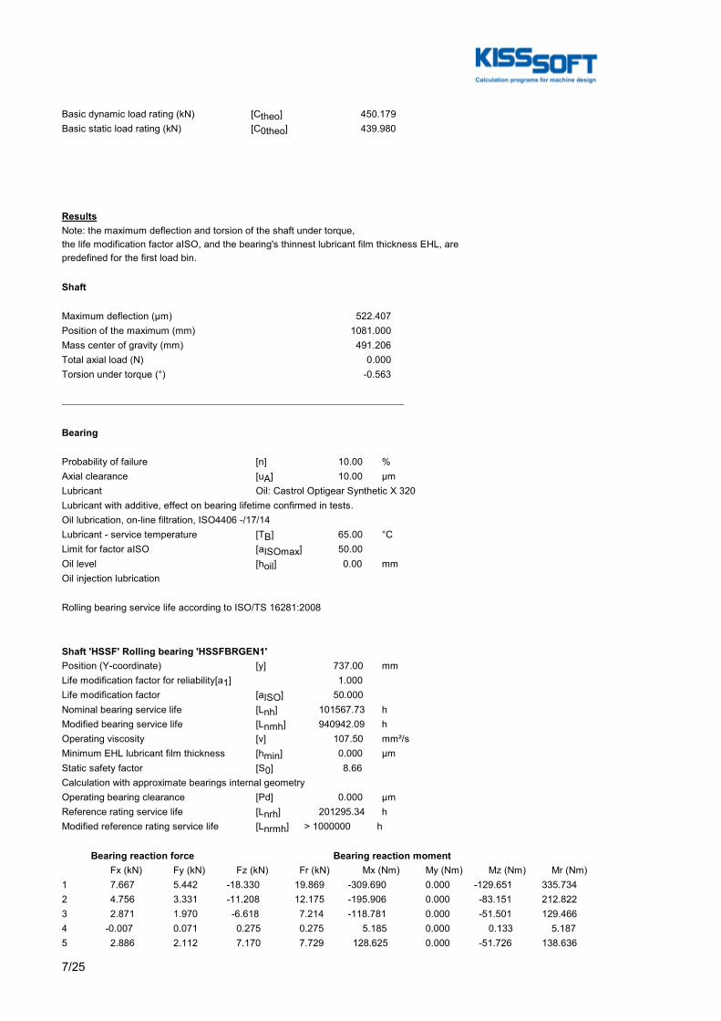
7/25
Basic dynamic load rating (kN) [Ctheo] 450.179Basic static load rating (kN) [C0theo] 439.980
ResultsNote: the maximum deflection and torsion of the shaft under torque,the life modification factor aISO, and the bearing's thinnest lubricant film thickness EHL, arepredefined for the first load bin.
Shaft
Maximum deflection (μm) 522.407Position of the maximum (mm) 1081.000Mass center of gravity (mm) 491.206Total axial load (N) 0.000Torsion under torque (°) -0.563
Bearing
Probability of failure [n] 10.00 %Axial clearance [uA] 10.00 µmLubricant Oil: Castrol Optigear Synthetic X 320Lubricant with additive, effect on bearing lifetime confirmed in tests.Oil lubrication, on-line filtration, ISO4406 -/17/14Lubricant - service temperature [TB] 65.00 °CLimit for factor aISO [aISOmax] 50.00Oil level [hoil] 0.00 mmOil injection lubrication
Rolling bearing service life according to ISO/TS 16281:2008
Shaft 'HSSF' Rolling bearing 'HSSFBRGEN1'Position (Y-coordinate) [y] 737.00 mmLife modification factor for reliability[a1] 1.000Life modification factor [aISO] 50.000Nominal bearing service life [Lnh] 101567.73 hModified bearing service life [Lnmh] 940942.09 hOperating viscosity [ν] 107.50 mm²/sMinimum EHL lubricant film thickness [hmin] 0.000 µmStatic safety factor [S0] 8.66Calculation with approximate bearings internal geometryOperating bearing clearance [Pd] 0.000 µmReference rating service life [Lnrh] 201295.34 hModified reference rating service life [Lnrmh] > 1000000 h
Bearing reaction force Bearing reaction moment Fx (kN) Fy (kN) Fz (kN) Fr (kN) Mx (Nm) My (Nm) Mz (Nm) Mr (Nm)1 7.667 5.442 -18.330 19.869 -309.690 0.000 -129.651 335.7342 4.756 3.331 -11.208 12.175 -195.906 0.000 -83.151 212.8223 2.871 1.970 -6.618 7.214 -118.781 0.000 -51.501 129.4664 -0.007 0.071 0.275 0.275 5.185 0.000 0.133 5.1875 2.886 2.112 7.170 7.729 128.625 0.000 -51.726 138.636

8/25
6 5.658 4.113 13.916 15.023 240.515 0.000 -97.784 259.6337 8.590 6.231 21.059 22.744 352.411 0.000 -143.861 380.6438 12.462 9.021 30.460 32.911 493.063 0.000 -201.809 532.7649 15.446 11.179 37.724 40.763 597.850 0.000 -245.071 646.13010 18.449 13.348 45.017 48.651 700.815 0.000 -287.275 757.40911 21.467 15.537 52.363 56.593 803.382 0.000 -329.808 868.445
Displacement of bearing Misalignment of bearing ux (µm) uy (µm) uz (µm) rr (µm) rx (mrad) ry (mrad) rz (mrad) rr (mrad)1 -16.1070 26.1111 38.5714 41.7994 -0.634 1.070 -0.260 0.6852 -11.5365 19.2368 27.1413 29.4914 -0.412 0.667 -0.174 0.4473 -8.3018 14.6245 18.9825 20.7185 -0.265 0.403 -0.117 0.2904 0.2935 7.5042 -4.1892 4.1994 0.053 -0.000 0.010 0.0545 -8.1118 14.7782 -19.8180 21.4139 0.273 -0.403 -0.115 0.2976 -12.8302 21.5003 -31.4220 33.9405 0.488 -0.789 -0.198 0.5267 -17.3807 28.3441 -42.4873 45.9049 0.708 -1.193 -0.286 0.7648 -23.0167 37.0114 -56.0532 60.5948 0.991 -1.719 -0.404 1.0709 -27.1893 43.5653 -66.0627 71.4390 1.207 -2.123 -0.493 1.30410 -31.2347 50.0060 -75.8345 82.0151 1.422 -2.526 -0.583 1.53611 -35.2594 56.3504 -85.4363 92.4261 1.636 -2.930 -0.672 1.769
Shaft 'HSSF' Rolling bearing 'HSSFBRGEN2'Position (Y-coordinate) [y] 789.00 mmLife modification factor for reliability[a1] 1.000Life modification factor [aISO] 50.000Nominal bearing service life [Lnh] 144488.09 hModified bearing service life [Lnmh] 999719.81 hOperating viscosity [ν] 107.50 mm²/sMinimum EHL lubricant film thickness [hmin] 0.000 µmStatic safety factor [S0] 9.91Calculation with approximate bearings internal geometryOperating bearing clearance [Pd] 0.000 µmReference rating service life [Lnrh] 365670.16 hModified reference rating service life [Lnrmh] > 1000000 h
Bearing reaction force Bearing reaction moment Fx (kN) Fy (kN) Fz (kN) Fr (kN) Mx (Nm) My (Nm) Mz (Nm) Mr (Nm)1 7.110 -5.437 -16.688 18.139 357.337 0.000 151.957 388.3052 4.446 -3.327 -10.391 11.302 215.924 0.000 92.363 234.8493 2.697 -1.966 -6.235 6.794 126.515 0.000 54.750 137.8544 0.007 -0.071 0.267 0.267 -5.178 0.000 0.135 5.1805 2.682 -2.108 6.768 7.280 -137.390 0.000 54.535 147.8176 5.241 -4.109 12.851 13.878 -269.767 0.000 110.063 291.3557 7.885 -6.226 19.130 20.691 -412.624 0.000 169.888 446.2298 11.290 -9.016 27.245 29.492 -604.477 0.000 250.096 654.1719 13.887 -11.173 33.416 36.187 -754.018 0.000 312.670 816.27610 16.466 -13.342 39.561 42.851 -905.950 0.000 376.254 980.97511 19.032 -15.531 45.657 49.465 -1058.796 0.000 440.073 1146.610
Displacement of bearing Misalignment of bearing ux (µm) uy (µm) uz (µm) rr (µm) rx (mrad) ry (mrad) rz (mrad) rr (mrad)1 -1.8198 13.9764 3.7501 4.1684 -0.639 1.700 -0.262 0.6912 -2.0303 7.1699 4.5554 4.9874 -0.416 1.059 -0.175 0.4513 -1.9083 2.6013 4.4720 4.8622 -0.268 0.641 -0.118 0.2934 -0.2408 -4.4581 -1.4411 1.4611 0.052 -0.000 0.010 0.0535 -1.8310 2.7505 -4.9166 5.2465 0.274 -0.641 -0.116 0.297
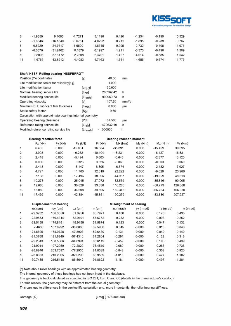
9/25
6 -1.9659 9.4083 -4.7271 5.1196 0.490 -1.254 -0.199 0.5297 -1.6346 16.1840 -3.6751 4.0222 0.711 -1.895 -0.288 0.7678 -0.8229 24.7617 -1.6620 1.8545 0.995 -2.732 -0.406 1.0759 -0.0676 31.2462 0.1879 0.1997 1.211 -3.373 -0.496 1.30910 0.8006 37.6172 2.2308 2.3701 1.427 -4.014 -0.585 1.54211 1.6765 43.8912 4.4082 4.7163 1.641 -4.655 -0.674 1.775
Shaft 'HSSF' Rolling bearing 'HSSFBRROT'Position (Y-coordinate) [y] 40.50 mmLife modification factor for reliability[a1] 1.000Life modification factor [aISO] 50.000Nominal bearing service life [Lnh] 260962.42 hModified bearing service life [Lnmh] 999969.73 hOperating viscosity [ν] 107.50 mm²/sMinimum EHL lubricant film thickness [hmin] 0.000 µmStatic safety factor [S0] 9.60Calculation with approximate bearings internal geometryOperating bearing clearance [Pd] 67.500 µmReference rating service life [Lnrh] 479632.19 hModified reference rating service life [Lnrmh] > 1000000 h
Bearing reaction force Bearing reaction moment Fx (kN) Fy (kN) Fz (kN) Fr (kN) Mx (Nm) My (Nm) Mz (Nm) Mr (Nm)1 6.405 0.000 -15.081 16.384 -35.891 0.000 -15.499 39.0952 3.993 0.000 -9.282 10.104 -15.231 0.000 -6.427 16.5313 2.418 0.000 -5.494 6.003 -5.645 0.000 -2.377 6.1254 0.000 0.000 0.326 0.326 -0.060 0.000 -0.003 0.0605 2.418 0.000 6.147 6.605 6.574 0.000 -2.482 7.0276 4.727 0.000 11.700 12.619 22.222 0.000 -9.029 23.9867 7.138 0.000 17.496 18.896 44.957 0.000 -19.029 48.8188 10.278 0.000 25.045 27.072 82.559 0.000 -35.846 90.0059 12.685 0.000 30.829 33.336 116.265 0.000 -50.773 126.86810 15.088 0.000 36.608 39.595 152.343 0.000 -66.764 166.33011 17.492 0.000 42.384 45.851 190.279 0.000 -83.830 207.927
Displacement of bearing Misalignment of bearing ux (µm) uy (µm) uz (µm) rr (µm) rx (mrad) ry (mrad) rz (mrad) rr (mrad)1 -22.3202 186.3056 61.8956 65.7971 0.400 0.000 0.173 0.4352 -22.9553 179.4314 52.9101 57.6752 0.232 0.000 0.098 0.2523 -23.5159 174.8191 45.9159 51.5874 0.123 0.000 0.047 0.1324 7.4680 167.6992 -38.8860 39.5966 0.045 -0.000 0.010 0.0465 -21.8695 174.9728 -47.8908 52.6480 -0.131 -0.000 0.049 0.1406 -21.3768 181.6949 -57.4310 61.2804 -0.291 -0.000 0.122 0.3167 -22.2643 188.5386 -64.8991 68.6119 -0.459 -0.000 0.195 0.4998 -24.9014 197.2059 -72.2829 76.4519 -0.680 -0.000 0.288 0.7389 -26.8946 203.7597 -77.2935 81.8389 -0.848 -0.000 0.358 0.92010 -28.8633 210.2005 -82.0290 86.9589 -1.016 -0.000 0.427 1.10211 -30.7455 216.5448 -86.5642 91.8622 -1.184 -0.000 0.497 1.284
(*) Note about roller bearings with an approximated bearing geometry:The internal geometry of these bearings has not been input in the database.The geometry is back-calculated as specified in ISO 281, from C and C0 (details in the manufacturer's catalog).For this reason, the geometry may be different from the actual geometry.This can lead to differences in the service life calculation and, more importantly, the roller bearing stiffness.
Damage (%) [Lreq] ( 175200.000)
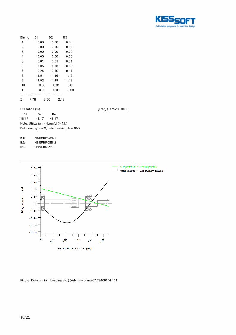
10/25
Bin no B1 B2 B3 1 0.00 0.00 0.00 2 0.00 0.00 0.00 3 0.00 0.00 0.00 4 0.00 0.00 0.00 5 0.01 0.01 0.01 6 0.05 0.03 0.03 7 0.24 0.10 0.11 8 3.51 1.36 1.19 9 3.92 1.48 1.13 10 0.03 0.01 0.01 11 0.00 0.00 0.00------------------------------------------Σ 7.76 3.00 2.48
Utilization (%) [Lreq] ( 175200.000) B1 B2 B348.17 48.17 48.17Note: Utilization = (Lreq/Lh)^(1/k)Ball bearing: k = 3, roller bearing: k = 10/3
B 1: HSSFBRGEN1B 2: HSSFBRGEN2B 3: HSSFBRROT
Figure: Deformation (bending etc.) (Arbitrary plane 67.79409544 121)
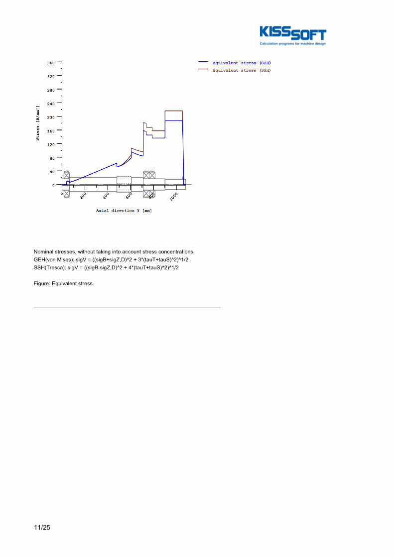
11/25
Nominal stresses, without taking into account stress concentrationsGEH(von Mises): sigV = ((sigB+sigZ,D)^2 + 3*(tauT+tauS)^2)^1/2SSH(Tresca): sigV = ((sigB-sigZ,D)^2 + 4*(tauT+tauS)^2)^1/2
Figure: Equivalent stress
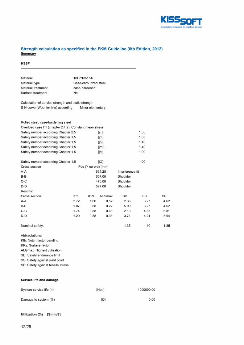
12/25
Strength calculation as specified in the FKM Guideline (6th Edition, 2012)Summary
HSSF
Material 18CrNiMo7-6Material type Case-carburized steelMaterial treatment case-hardenedSurface treatment No
Calculation of service strength and static strengthS-N curve (Woehler line) according Miner elementary
Rolled steel, case-hardening steelOverload case F1 (chapter 2.4.2): Constant mean stressSafety number according Chapter 2.5 [jF] 1.35Safety number according Chapter 1.5 [jm] 1.85Safety number according Chapter 1.5 [jp] 1.40Safety number according Chapter 1.5 [jmt] 1.40Safety number according Chapter 1.5 [jpt] 1.00
Safety number according Chapter 1.5 [jG] 1.00Cross section Pos (Y co-ord) (mm)A-A 661.25 Interference fitB-B 657.00 ShoulderC-C 470.00 ShoulderD-D 597.00 ShoulderResults:Cross section Kfb KRs ALGmax SD SS SBA-A 2.72 1.00 0.57 2.35 3.27 4.62B-B 1.07 0.88 0.27 5.09 3.27 4.62C-C 1.74 0.88 0.63 2.13 4.83 6.81D-D 1.29 0.88 0.36 3.71 4.21 5.94
Nominal safety: 1.35 1.40 1.85
Abbreviations:Kfb: Notch factor bendingKRs: Surface factorALGmax: Highest utilizationSD: Safety endurance limitSS: Safety against yield pointSB: Safety against tensile stress
Service life and damage
System service life (h) [Hatt] 1000000.00
Damage to system (%) [D] 0.00
Utilization (%) [Smin/S]

13/25
Cross section Static EnduranceA-A 42.750 57.403B-B 42.750 26.508C-C 29.014 63.445D-D 33.253 36.400
Maximum utilization (%) [A] 63.445

14/25
Utilization = Smin/S (%)
Figure: Strength
Calculation details
General statements
Label HSSFDrawingLength (mm) [l] 1081.00Speed (1/min) [n] 1495.38
Material 18CrNiMo7-6Material type Case-carburized steelMaterial treatment case-hardenedSurface treatment No
Tension/Compression Bending Torsion ShearingLoad factor static calculation 1.700 1.700 1.700 1.700Load factor endurance limit 1.000 1.000 1.000 1.000
Rolled steel, case-hardening steel
Base stress according FKM chapter 5.1:Tensile strength (N/mm²) [Rm,N] 1200.00Yield point (N/mm²) [Rp,N] 850.00Fatigue limit (N/mm²) [σzdWN] 480.00Fatigue limit (N/mm²) [σbWN] 510.00

15/25
Fatigue limit (N/mm²) [τtWN] 305.00Fatigue limit (N/mm²) [τsWN] 280.00Breaking elongation (%) [A] 8.00Reference diameter (mm) [deffNm, deffNp] 16.00 16.00
Required life time [H] 175200.00Number of load cycles [NL] 15719483077Service strength for a load spectrumS-N curve (Woehler lines) according to Miner elementary according to FKM guidelineTemperature (°C) [Temperatur] 20.000Temperature duration (h) [TemperaturD] 175200.000Temperature coefficients [KTm, KTp, KTD] 1.000 1.000 1.000 [KTtm, KTtp] 1.000 1.000Internal stress coefficient [KEs, KEt] 1.000 1.000Additional coefficients [KA, KW, KfW] 1.000 1.000 1.000 [KNL, KNLE] 1.000 1.000Protective layer factor [KS] 1.000
Material properties: [fσZ, fσD, fτ, Rpmax] 1.000 1.000 0.577 1150.0 [fWt, fWs] 0.577 0.400 [aM, bM, aTD] 0.35000 -0.100 1.400 [aG, bG, aRsig, RmNmin] 0.500 2700.0 0.220 400.0 [MS, MT] 0.1959 0.1131 [kσ, kτ] 15 25 [kDσ, kDτ] 0 0 [NDσ, NDτ] 1e+006 1e+006 [NDσII, NDτII] 0 0
Thickness of raw material (mm) [d.eff] 140.00Material data calculated acc. FKM directive with Kdm, KdpGeometric size factors (Kdm, Kdp) calculated from raw diameterMaterial strength calculated from size of raw materialConstants [adm, adp] 0.370 0.370Size factors [Kdm, Kdp] 0.704 0.704Tensile strength (N/mm²) [Rm] 845.34Yield point (N/mm²) [Rp] 598.79σzdW (N/mm²) [σzdW] 338.14σbW (N/mm²) [σbW] 359.27τtW (N/mm²) [τtW] 214.86τsW (N/mm²) [τsW] 197.25
Overload case F1 (chapter 2.4.2): Constant mean stressSafety number according Chapter 1.5 [jm] 1.85Safety number according Chapter 1.5 [jp] 1.40Safety number according Chapter 1.5 [jmt] 1.40Safety number according Chapter 1.5 [jpt] 1.00Safety number according Chapter 2.5 [jF] 1.35
Safety number according Chapter 1.5 [jG] 1.00
Cross section 'A-A' Interference fitComment Fit at bearing 1Position (Y-Coordinate) (mm) [y] 661.250
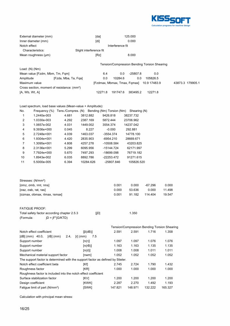
16/25
External diameter (mm) [da] 125.000Inner diameter (mm) [di] 0.000Notch effect Interference fit Characteristics: Slight interference fitMean roughness (µm) [Rz] 8.000
Tension/Compression Bending Torsion ShearingLoad: (N) (Nm)Mean value [Fzdm, Mbm, Tm, Fqm] 6.4 0.0 -25807.8 0.0Amplitude [Fzda, Mba, Ta, Fqa] 0.0 10284.6 0.0 105826.5Maximum value [Fzdmax, Mbmax, Tmax, Fqmax] 10.9 17483.9 43873.3 179905.1Cross section, moment of resistance: (mm²)[A, Wb, Wt, A] 12271.8 191747.6 383495.2 12271.8
Load spectrum, load base values (Mean-value + Amplitude):No. Frequency (%) Tens./Compres. (N) Bending (Nm) Torsion (Nm) Shearing (N) 1 1.2440e-003 4.681 3812.882 9426.818 38237.732 2 1.0330e-003 4.292 2387.169 5872.444 23706.962 3 1.0657e-002 4.031 1449.002 3554.374 14237.042 4 9.3936e+000 0.045 8.227 -0.000 292.881 5 2.7248e+001 4.039 1463.037 -3554.374 14778.100 6 1.9304e+001 4.420 2835.903 -6954.210 28669.671 7 1.3095e+001 4.808 4257.278 -10508.584 43203.825 8 2.3136e+001 5.299 6095.956 -15144.724 62171.997 9 7.7924e+000 5.670 7497.293 -18699.098 76719.182 10 1.8943e-002 6.035 8892.786 -22253.472 91271.615 11 5.5000e-005 6.394 10284.626 -25807.846 105826.520
Stresses: (N/mm²)[σmz, σmb, τmt, τms] 0.001 0.000 -67.296 0.000[σaz, σab, τat, τas] 0.000 53.636 0.000 11.498[σzmax, σbmax, τtmax, τsmax] 0.001 91.182 114.404 19.547
FATIQUE PROOF:Total safety factor according chapter 2.5.3 [jD] 1.350(Formula: jD = jF*jG/KTD)
Tension/Compression Bending Torsion ShearingNotch effect coefficient [β(dB)] 2.591 2.591 1.716 1.358[dB] (mm) 40.0, [rB] (mm) 2.4, [r] (mm) 7.5Support number [n(r)] 1.097 1.097 1.076 1.076Support number [n(rB)] 1.163 1.163 1.135 1.135Support number [n(d)] 1.008 1.008 1.011 1.011Mechanical material support factor [nwm] 1.052 1.052 1.052 1.052The support factor is determined with the support factor as defined by Stieler.Notch effect coefficient beta [Kf] 2.745 2.724 1.790 1.432Roughness factor [KR] 1.000 1.000 1.000 1.000Roughness factor is included into the notch effect coefficientSurface stabilization factor [KV] 1.200 1.200 1.200 1.200Design coefficient [KWK] 2.287 2.270 1.492 1.193Fatigue limit of part (N/mm²) [SWK] 147.821 148.971 132.222 165.327
Calculation with principal mean stress:
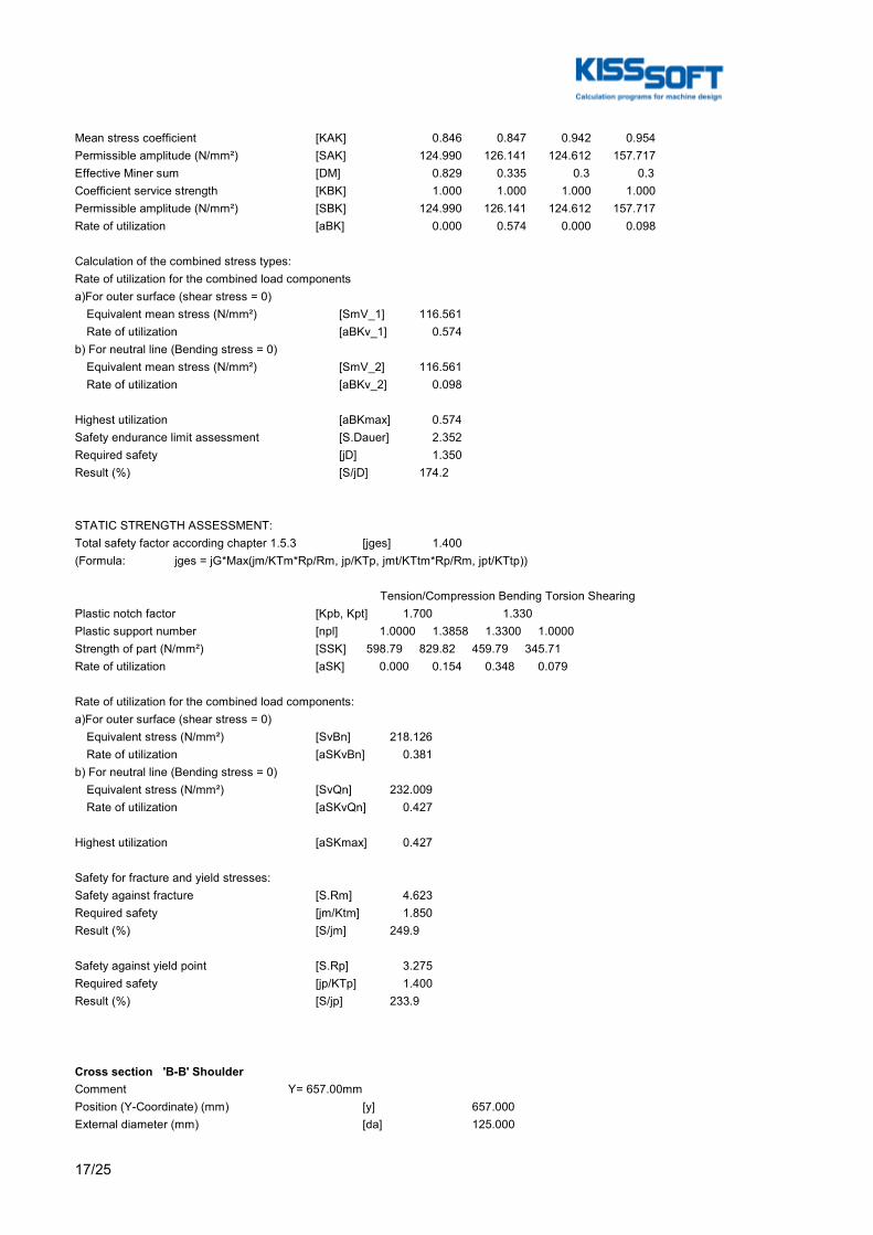
17/25
Mean stress coefficient [KAK] 0.846 0.847 0.942 0.954Permissible amplitude (N/mm²) [SAK] 124.990 126.141 124.612 157.717Effective Miner sum [DM] 0.829 0.335 0.3 0.3Coefficient service strength [KBK] 1.000 1.000 1.000 1.000Permissible amplitude (N/mm²) [SBK] 124.990 126.141 124.612 157.717Rate of utilization [aBK] 0.000 0.574 0.000 0.098
Calculation of the combined stress types:Rate of utilization for the combined load componentsa)For outer surface (shear stress = 0) Equivalent mean stress (N/mm²) [SmV_1] 116.561 Rate of utilization [aBKv_1] 0.574b) For neutral line (Bending stress = 0) Equivalent mean stress (N/mm²) [SmV_2] 116.561 Rate of utilization [aBKv_2] 0.098
Highest utilization [aBKmax] 0.574Safety endurance limit assessment [S.Dauer] 2.352Required safety [jD] 1.350Result (%) [S/jD] 174.2
STATIC STRENGTH ASSESSMENT:Total safety factor according chapter 1.5.3 [jges] 1.400(Formula: jges = jG*Max(jm/KTm*Rp/Rm, jp/KTp, jmt/KTtm*Rp/Rm, jpt/KTtp))
Tension/Compression Bending Torsion ShearingPlastic notch factor [Kpb, Kpt] 1.700 1.330Plastic support number [npl] 1.0000 1.3858 1.3300 1.0000Strength of part (N/mm²) [SSK] 598.79 829.82 459.79 345.71Rate of utilization [aSK] 0.000 0.154 0.348 0.079
Rate of utilization for the combined load components:a)For outer surface (shear stress = 0) Equivalent stress (N/mm²) [SvBn] 218.126 Rate of utilization [aSKvBn] 0.381b) For neutral line (Bending stress = 0) Equivalent stress (N/mm²) [SvQn] 232.009 Rate of utilization [aSKvQn] 0.427
Highest utilization [aSKmax] 0.427
Safety for fracture and yield stresses:Safety against fracture [S.Rm] 4.623Required safety [jm/Ktm] 1.850Result (%) [S/jm] 249.9
Safety against yield point [S.Rp] 3.275Required safety [jp/KTp] 1.400Result (%) [S/jp] 233.9
Cross section 'B-B' ShoulderComment Y= 657.00mmPosition (Y-Coordinate) (mm) [y] 657.000External diameter (mm) [da] 125.000
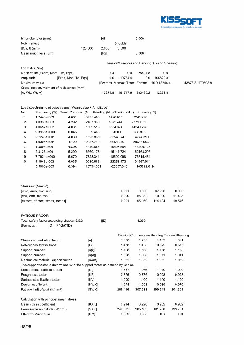
18/25
Inner diameter (mm) [di] 0.000Notch effect Shoulder[D, r, t] (mm) 126.000 2.000 0.500Mean roughness (µm) [Rz] 8.000
Tension/Compression Bending Torsion ShearingLoad: (N) (Nm)Mean value [Fzdm, Mbm, Tm, Fqm] 6.4 0.0 -25807.8 0.0Amplitude [Fzda, Mba, Ta, Fqa] 0.0 10734.4 0.0 105822.8Maximum value [Fzdmax, Mbmax, Tmax, Fqmax] 10.9 18248.4 43873.3 179898.8Cross section, moment of resistance: (mm²)[A, Wb, Wt, A] 12271.8 191747.6 383495.2 12271.8
Load spectrum, load base values (Mean-value + Amplitude):No. Frequency (%) Tens./Compres. (N) Bending (Nm) Torsion (Nm) Shearing (N) 1 1.2440e-003 4.681 3975.400 9426.818 38241.426 2 1.0330e-003 4.292 2487.930 5872.444 23710.653 3 1.0657e-002 4.031 1509.516 3554.374 14240.728 4 9.3936e+000 0.045 9.463 -0.000 288.876 5 2.7248e+001 4.039 1525.835 -3554.374 14774.390 6 1.9304e+001 4.420 2957.740 -6954.210 28665.966 7 1.3095e+001 4.808 4440.886 -10508.584 43200.123 8 2.3136e+001 5.299 6360.178 -15144.724 62168.296 9 7.7924e+000 5.670 7823.341 -18699.098 76715.481 10 1.8943e-002 6.035 9280.683 -22253.472 91267.914 11 5.5000e-005 6.394 10734.381 -25807.846 105822.819
Stresses: (N/mm²)[σmz, σmb, τmt, τms] 0.001 0.000 -67.296 0.000[σaz, σab, τat, τas] 0.000 55.982 0.000 11.498[σzmax, σbmax, τtmax, τsmax] 0.001 95.169 114.404 19.546
FATIQUE PROOF:Total safety factor according chapter 2.5.3 [jD] 1.350(Formula: jD = jF*jG/KTD)
Tension/Compression Bending Torsion ShearingStress concentration factor [a] 1.620 1.255 1.182 1.091References stress slope [G'] 1.438 1.438 0.575 0.575Support number [n(r)] 1.168 1.168 1.158 1.158Support number [n(d)] 1.008 1.008 1.011 1.011Mechanical material support factor [nwm] 1.052 1.052 1.052 1.052The support factor is determined with the support factor as defined by Stieler.Notch effect coefficient beta [Kf] 1.387 1.066 1.010 1.000Roughness factor [KR] 0.876 0.876 0.928 0.928Surface stabilization factor [KV] 1.200 1.100 1.100 1.100Design coefficient [KWK] 1.274 1.098 0.989 0.979Fatigue limit of part (N/mm²) [SWK] 265.416 307.933 199.518 201.391
Calculation with principal mean stress:Mean stress coefficient [KAK] 0.914 0.926 0.962 0.962Permissible amplitude (N/mm²) [SAK] 242.585 285.103 191.908 193.781Effective Miner sum [DM] 0.829 0.335 0.3 0.3
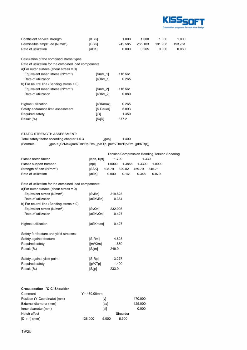
19/25
Coefficient service strength [KBK] 1.000 1.000 1.000 1.000Permissible amplitude (N/mm²) [SBK] 242.585 285.103 191.908 193.781Rate of utilization [aBK] 0.000 0.265 0.000 0.080
Calculation of the combined stress types:Rate of utilization for the combined load componentsa)For outer surface (shear stress = 0) Equivalent mean stress (N/mm²) [SmV_1] 116.561 Rate of utilization [aBKv_1] 0.265b) For neutral line (Bending stress = 0) Equivalent mean stress (N/mm²) [SmV_2] 116.561 Rate of utilization [aBKv_2] 0.080
Highest utilization [aBKmax] 0.265Safety endurance limit assessment [S.Dauer] 5.093Required safety [jD] 1.350Result (%) [S/jD] 377.2
STATIC STRENGTH ASSESSMENT:Total safety factor according chapter 1.5.3 [jges] 1.400(Formula: jges = jG*Max(jm/KTm*Rp/Rm, jp/KTp, jmt/KTtm*Rp/Rm, jpt/KTtp))
Tension/Compression Bending Torsion ShearingPlastic notch factor [Kpb, Kpt] 1.700 1.330Plastic support number [npl] 1.0000 1.3858 1.3300 1.0000Strength of part (N/mm²) [SSK] 598.79 829.82 459.79 345.71Rate of utilization [aSK] 0.000 0.161 0.348 0.079
Rate of utilization for the combined load components:a)For outer surface (shear stress = 0) Equivalent stress (N/mm²) [SvBn] 219.823 Rate of utilization [aSKvBn] 0.384b) For neutral line (Bending stress = 0) Equivalent stress (N/mm²) [SvQn] 232.008 Rate of utilization [aSKvQn] 0.427
Highest utilization [aSKmax] 0.427
Safety for fracture and yield stresses:Safety against fracture [S.Rm] 4.623Required safety [jm/Ktm] 1.850Result (%) [S/jm] 249.9
Safety against yield point [S.Rp] 3.275Required safety [jp/KTp] 1.400Result (%) [S/jp] 233.9
Cross section 'C-C' ShoulderComment Y= 470.00mmPosition (Y-Coordinate) (mm) [y] 470.000External diameter (mm) [da] 125.000Inner diameter (mm) [di] 0.000Notch effect Shoulder[D, r, t] (mm) 138.000 5.000 6.500
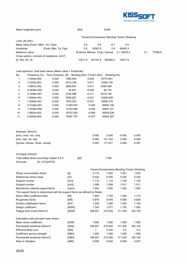
20/25
Mean roughness (µm) [Rz] 8.000
Tension/Compression Bending Torsion ShearingLoad: (N) (Nm)Mean value [Fzdm, Mbm, Tm, Fqm] 0.0 0.0 -0.1 0.0Amplitude [Fzda, Mba, Ta, Fqa] 0.0 19397.8 0.0 45462.3Maximum value [Fzdmax, Mbmax, Tmax, Fqmax] 0.1 32976.2 0.1 77285.9Cross section, moment of resistance: (mm²)[A, Wb, Wt, A] 12271.8 191747.6 383495.2 12271.8
Load spectrum, load base values (Mean-value + Amplitude):No. Frequency (%) Tens./Compres. (N) Bending (Nm) Torsion (Nm) Shearing (N) 1 1.2440e-003 0.000 7085.093 0.028 16772.901 2 1.0330e-003 0.000 4410.338 0.017 10492.730 3 1.0657e-002 0.000 2658.847 0.011 6390.489 4 9.3936e+000 0.045 45.691 -0.000 94.774 5 2.7248e+001 0.000 2742.096 -0.011 6215.138 6 1.9304e+001 0.000 5308.281 -0.021 12229.509 7 1.3095e+001 -0.000 7979.343 -0.031 18506.378 8 2.3136e+001 0.000 11450.070 -0.045 26683.160 9 7.7924e+000 0.000 14103.586 -0.056 32947.161 10 1.8943e-002 -0.000 16752.262 -0.066 39205.939 11 5.5000e-005 -0.000 19397.757 -0.077 45462.267
Stresses: (N/mm²)[σmz, σmb, τmt, τms] 0.000 0.000 -0.000 0.000[σaz, σab, τat, τas] 0.000 101.163 0.000 4.939[σzmax, σbmax, τtmax, τsmax] 0.000 171.977 0.000 8.397
FATIQUE PROOF:Total safety factor according chapter 2.5.3 [jD] 1.350(Formula: jD = jF*jG/KTD)
Tension/Compression Bending Torsion ShearingStress concentration factor [a] 2.116 1.953 1.451 1.225References stress slope [G'] 0.530 0.530 0.230 0.230Support number [n(r)] 1.112 1.112 1.100 1.100Support number [n(d)] 1.008 1.008 1.011 1.011Mechanical material support factor [nwm] 1.052 1.052 1.052 1.052The support factor is determined with the support factor as defined by Stieler.Notch effect coefficient beta [Kf] 1.903 1.743 1.305 1.114Roughness factor [KR] 0.876 0.876 0.928 0.928Surface stabilization factor [KV] 1.200 1.200 1.200 1.100Design coefficient [KWK] 1.704 1.571 1.152 1.083Fatigue limit of part (N/mm²) [SWK] 198.457 215.259 171.230 182.135
Calculation with principal mean stress:Mean stress coefficient [KAK] 1.000 1.000 1.000 1.000Permissible amplitude (N/mm²) [SAK] 198.457 215.259 171.230 182.135Effective Miner sum [DM] 1 0.332 0.3 0.3Coefficient service strength [KBK] 1.000 1.000 1.000 1.000Permissible amplitude (N/mm²) [SBK] 198.457 215.259 171.230 182.135Rate of utilization [aBK] 0.000 0.634 0.000 0.037

21/25
Calculation of the combined stress types:Rate of utilization for the combined load componentsa)For outer surface (shear stress = 0) Equivalent mean stress (N/mm²) [SmV_1] 0.000 Rate of utilization [aBKv_1] 0.634b) For neutral line (Bending stress = 0) Equivalent mean stress (N/mm²) [SmV_2] 0.000 Rate of utilization [aBKv_2] 0.037
Highest utilization [aBKmax] 0.634Safety endurance limit assessment [S.Dauer] 2.128Required safety [jD] 1.350Result (%) [S/jD] 157.6
STATIC STRENGTH ASSESSMENT:Total safety factor according chapter 1.5.3 [jges] 1.400(Formula: jges = jG*Max(jm/KTm*Rp/Rm, jp/KTp, jmt/KTtm*Rp/Rm, jpt/KTtp))
Tension/Compression Bending Torsion ShearingPlastic notch factor [Kpb, Kpt] 1.700 1.330Plastic support number [npl] 1.0000 1.3858 1.3300 1.0000Strength of part (N/mm²) [SSK] 598.79 829.82 459.79 345.71Rate of utilization [aSK] 0.000 0.290 0.000 0.034
Rate of utilization for the combined load components:a)For outer surface (shear stress = 0) Equivalent stress (N/mm²) [SvBn] 171.977 Rate of utilization [aSKvBn] 0.290b) For neutral line (Bending stress = 0) Equivalent stress (N/mm²) [SvQn] 14.545 Rate of utilization [aSKvQn] 0.034
Highest utilization [aSKmax] 0.290
Safety for fracture and yield stresses:Safety against fracture [S.Rm] 6.812Required safety [jm/Ktm] 1.850Result (%) [S/jm] 368.2
Safety against yield point [S.Rp] 4.825Required safety [jp/KTp] 1.400Result (%) [S/jp] 344.7
Cross section 'D-D' ShoulderComment Y= 597.00mmPosition (Y-Coordinate) (mm) [y] 597.000External diameter (mm) [da] 134.000Inner diameter (mm) [di] 0.000Notch effect Shoulder[D, r, t] (mm) 138.000 5.000 2.000Mean roughness (µm) [Rz] 8.000
Tension/Compression Bending Torsion Shearing

22/25
Load: (N) (Nm)Mean value [Fzdm, Mbm, Tm, Fqm] 6.4 0.0 -23775.7 0.0Amplitude [Fzda, Mba, Ta, Fqa] 0.0 17022.7 0.0 93869.3Maximum value [Fzdmax, Mbmax, Tmax, Fqmax] 10.9 28938.5 40418.8 159577.9Cross section, moment of resistance: (mm²)[A, Wb, Wt, A] 14102.6 236218.7 472437.4 14102.6
Load spectrum, load base values (Mean-value + Amplitude):No. Frequency (%) Tens./Compres. (N) Bending (Nm) Torsion (Nm) Shearing (N) 1 1.2440e-003 4.681 6249.721 8684.551 33948.209 2 1.0330e-003 4.292 3898.597 5410.048 21056.324 3 1.0657e-002 4.031 2357.327 3274.503 12655.208 4 9.3936e+000 0.045 25.092 -0.000 230.920 5 2.7248e+001 4.039 2402.522 -3274.503 13081.841 6 1.9304e+001 4.420 4660.087 -6406.636 25405.814 7 1.3095e+001 4.808 7007.089 -9681.139 38301.075 8 2.3136e+001 5.299 10053.784 -13952.230 55131.543 9 7.7924e+000 5.670 12381.583 -17226.732 68039.817 10 1.8943e-002 6.035 14703.876 -20501.235 80953.339 11 5.5000e-005 6.394 17022.674 -23775.738 93869.330
Stresses: (N/mm²)[σmz, σmb, τmt, τms] 0.000 0.000 -50.326 0.000[σaz, σab, τat, τas] 0.000 72.063 0.000 8.875[σzmax, σbmax, τtmax, τsmax] 0.001 122.507 85.554 15.087
FATIQUE PROOF:Total safety factor according chapter 2.5.3 [jD] 1.350(Formula: jD = jF*jG/KTD)
Tension/Compression Bending Torsion ShearingStress concentration factor [a] 1.735 1.443 1.248 1.124References stress slope [G'] 0.562 0.562 0.230 0.230Support number [n(r)] 1.115 1.115 1.100 1.100Support number [n(d)] 1.007 1.007 1.010 1.010Mechanical material support factor [nwm] 1.052 1.052 1.052 1.052The support factor is determined with the support factor as defined by Stieler.Notch effect coefficient beta [Kf] 1.556 1.285 1.124 1.022Roughness factor [KR] 0.876 0.876 0.928 0.928Surface stabilization factor [KV] 1.200 1.200 1.100 1.100Design coefficient [KWK] 1.415 1.189 1.092 0.999Fatigue limit of part (N/mm²) [SWK] 239.014 284.339 180.631 197.365
Calculation with principal mean stress:Mean stress coefficient [KAK] 0.929 0.940 0.968 0.971Permissible amplitude (N/mm²) [SAK] 221.941 267.266 174.940 191.674Effective Miner sum [DM] 0.829 0.333 0.3 0.3Coefficient service strength [KBK] 1.000 1.000 1.000 1.000Permissible amplitude (N/mm²) [SBK] 221.941 267.266 174.940 191.674Rate of utilization [aBK] 0.000 0.364 0.000 0.063
Calculation of the combined stress types:Rate of utilization for the combined load components
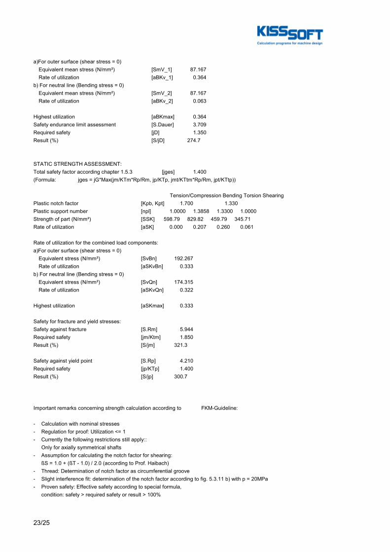
23/25
a)For outer surface (shear stress = 0) Equivalent mean stress (N/mm²) [SmV_1] 87.167 Rate of utilization [aBKv_1] 0.364b) For neutral line (Bending stress = 0) Equivalent mean stress (N/mm²) [SmV_2] 87.167 Rate of utilization [aBKv_2] 0.063
Highest utilization [aBKmax] 0.364Safety endurance limit assessment [S.Dauer] 3.709Required safety [jD] 1.350Result (%) [S/jD] 274.7
STATIC STRENGTH ASSESSMENT:Total safety factor according chapter 1.5.3 [jges] 1.400(Formula: jges = jG*Max(jm/KTm*Rp/Rm, jp/KTp, jmt/KTtm*Rp/Rm, jpt/KTtp))
Tension/Compression Bending Torsion ShearingPlastic notch factor [Kpb, Kpt] 1.700 1.330Plastic support number [npl] 1.0000 1.3858 1.3300 1.0000Strength of part (N/mm²) [SSK] 598.79 829.82 459.79 345.71Rate of utilization [aSK] 0.000 0.207 0.260 0.061
Rate of utilization for the combined load components:a)For outer surface (shear stress = 0) Equivalent stress (N/mm²) [SvBn] 192.267 Rate of utilization [aSKvBn] 0.333b) For neutral line (Bending stress = 0) Equivalent stress (N/mm²) [SvQn] 174.315 Rate of utilization [aSKvQn] 0.322
Highest utilization [aSKmax] 0.333
Safety for fracture and yield stresses:Safety against fracture [S.Rm] 5.944Required safety [jm/Ktm] 1.850Result (%) [S/jm] 321.3
Safety against yield point [S.Rp] 4.210Required safety [jp/KTp] 1.400Result (%) [S/jp] 300.7
Important remarks concerning strength calculation according to FKM-Guideline:
- Calculation with nominal stresses- Regulation for proof: Utilization <= 1- Currently the following restrictions still apply:: Only for axially symmetrical shafts- Assumption for calculating the notch factor for shearing: ßS = 1.0 + (ßT - 1.0) / 2.0 (according to Prof. Haibach)- Thread: Determination of notch factor as circumferential groove- Slight interference fit: determination of the notch factor according to fig. 5.3.11 b) with p = 20MPa- Proven safety: Effective safety according to special formula, condition: safety > required safety or result > 100%

24/25
End of Report lines: 1108

A.3. KISSsoft Report - Thermal analysis
A.3 KISSsoft Report - Thermal analysis
283

A. KISSsoft Reports
284

A.3. KISSsoft Report - Thermal analysis
A.3.1 KISSsoft Report - High speed shaft
285

A. KISSsoft Reports
286
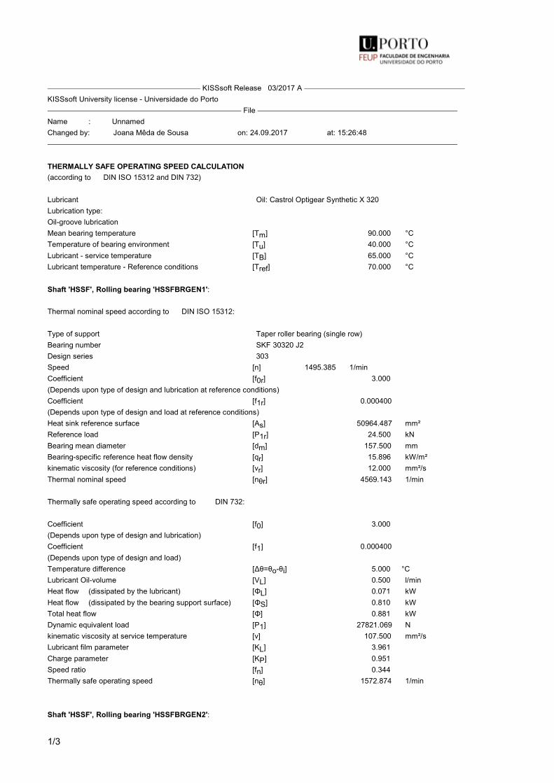
1/3
KISSsoft Release 03/2017 A KISSsoft University license - Universidade do Porto File Name : UnnamedChanged by: Joana Mêda de Sousa on: 24.09.2017 at: 15:26:48
THERMALLY SAFE OPERATING SPEED CALCULATION(according to DIN ISO 15312 and DIN 732)
Lubricant Oil: Castrol Optigear Synthetic X 320Lubrication type:Oil-groove lubricationMean bearing temperature [Tm] 90.000 °CTemperature of bearing environment [Tu] 40.000 °CLubricant - service temperature [TB] 65.000 °CLubricant temperature - Reference conditions [Tref] 70.000 °C
Shaft 'HSSF', Rolling bearing 'HSSFBRGEN1':
Thermal nominal speed according to DIN ISO 15312:
Type of support Taper roller bearing (single row)Bearing number SKF 30320 J2Design series 303Speed [n] 1495.385 1/minCoefficient [f0r] 3.000(Depends upon type of design and lubrication at reference conditions)Coefficient [f1r] 0.000400(Depends upon type of design and load at reference conditions)Heat sink reference surface [As] 50964.487 mm²Reference load [P1r] 24.500 kNBearing mean diameter [dm] 157.500 mmBearing-specific reference heat flow density [qr] 15.896 kW/m²kinematic viscosity (for reference conditions) [νr] 12.000 mm²/sThermal nominal speed [nθr] 4569.143 1/min
Thermally safe operating speed according to DIN 732:
Coefficient [f0] 3.000(Depends upon type of design and lubrication)Coefficient [f1] 0.000400(Depends upon type of design and load)Temperature difference [Δθ=θo-θi] 5.000 °CLubricant Oil-volume [VL] 0.500 l/minHeat flow (dissipated by the lubricant) [ΦL] 0.071 kWHeat flow (dissipated by the bearing support surface) [ΦS] 0.810 kWTotal heat flow [Φ] 0.881 kWDynamic equivalent load [P1] 27821.069 Nkinematic viscosity at service temperature [ν] 107.500 mm²/sLubricant film parameter [KL] 3.961Charge parameter [KP] 0.951Speed ratio [fn] 0.344Thermally safe operating speed [nθ] 1572.874 1/min
Shaft 'HSSF', Rolling bearing 'HSSFBRGEN2':

2/3
Thermal nominal speed according to DIN ISO 15312:
Type of support Taper roller bearing (single row)Bearing number SKF 30320 J2Design series 303Speed [n] 1495.385 1/minCoefficient [f0r] 3.000(Depends upon type of design and lubrication at reference conditions)Coefficient [f1r] 0.000400(Depends upon type of design and load at reference conditions)Heat sink reference surface [As] 50964.487 mm²Reference load [P1r] 24.500 kNBearing mean diameter [dm] 157.500 mmBearing-specific reference heat flow density [qr] 15.896 kW/m²kinematic viscosity (for reference conditions) [νr] 12.000 mm²/sThermal nominal speed [nθr] 4569.143 1/min
Thermally safe operating speed according to DIN 732:
Coefficient [f0] 3.000(Depends upon type of design and lubrication)Coefficient [f1] 0.000400(Depends upon type of design and load)Temperature difference [Δθ=θo-θi] 5.000 °CLubricant Oil-volume [VL] 0.500 l/minHeat flow (dissipated by the lubricant) [ΦL] 0.071 kWHeat flow (dissipated by the bearing support surface) [ΦS] 0.810 kWTotal heat flow [Φ] 0.881 kWDynamic equivalent load [P1] 26121.982 Nkinematic viscosity at service temperature [ν] 107.500 mm²/sLubricant film parameter [KL] 3.961Charge parameter [KP] 0.893Speed ratio [fn] 0.352Thermally safe operating speed [nθ] 1606.339 1/min
Shaft 'HSSF', Rolling bearing 'HSSFBRROT':
Thermal nominal speed according to DIN ISO 15312:
Type of support Cylindrical roller bearing (single row)Bearing number SKF NU 320 ECJDesign series 3Speed [n] 1495.385 1/minCoefficient [f0r] 2.000(Depends upon type of design and lubrication at reference conditions)Coefficient [f1r] 0.000350(Depends upon type of design and load at reference conditions)Heat sink reference surface [As] 46511.279 mm²Reference load [P1r] 22.000 kNBearing mean diameter [dm] 157.500 mmBearing-specific reference heat flow density [qr] 16.000 kW/m²kinematic viscosity (for reference conditions) [νr] 12.000 mm²/sThermal nominal speed [nθr] 5537.936 1/min
Thermally safe operating speed according to DIN 732:

3/3
Coefficient [f0] 2.000(Depends upon type of design and lubrication)Coefficient [f1] 0.000350(Depends upon type of design and load)Temperature difference [Δθ=θo-θi] 5.000 °CLubricant Oil-volume [VL] 0.500 l/minHeat flow (dissipated by the lubricant) [ΦL] 0.071 kWHeat flow (dissipated by the bearing support surface) [ΦS] 0.721 kWTotal heat flow [Φ] 0.792 kWDynamic equivalent load [P1] 22860.293 Nkinematic viscosity at service temperature [ν] 107.500 mm²/sLubricant film parameter [KL] 4.048Charge parameter [KP] 0.923Speed ratio [fn] 0.344Thermally safe operating speed [nθ] 1906.369 1/min
The reference conditions for calculating the thermal nominal speed are taken from theDIN ISO 15312 standard. End of Report lines: 134

A. KISSsoft Reports
290

Appendix B
Assembly drawing
291

B. Assembly drawing
292