
Design Method for Developing a Product Recovery ......Design Method for Developing a Product...
15
INTERNATIONAL JOURNAL OF PRECISION ENGINEERING AND MANUFACTURING-GREEN TECHNOLOGY Vol. 2, No. 2, pp. 173-187 APRIL 2015 / 173 © KSPE and Springer 2015 Design Method for Developing a Product Recovery Management System based on Life Cycle Information Jumyung Um 1 and Suk-Hwan Suh 2,# 1 Institute for Manufacturing, University of Cambridge, 10 Charles Babbage Road, Cambridge CB3 0FS, United Kingdom 2 Graduate School of Engineering Mastership, Pohang University of Science and Technology, 77, Cheongam-ro, Nam-gu, Pohang-si, Gyeongsangbuk-do, 790-784, South Korea # Corresponding Author / E-mail: [email protected], TEL: +82-54-279-2196, FAX: +82-54-279-0138 KEYWORDS: Product recovery management system, UbiDMR, End-of-Life, Remanufacturing Due to concerns about environmental protection, product life cycle management for end-of-life has received increasing attention in many industrial sectors. To support these functions, crucial issues have been studied to realize a product recovery management system. Until the present time most research has been concerned with decision making under the assumption that all the relevant and accurate information about a product is available by some means. However, these pieces of research ended in technological attempts because of the development complexity of implementation using ubiquitous computing devices such as identification chips and embedded systems to get data from products. An efficient development method is necessary in order to overcome this limitation. In this paper we overview a generic architecture based on ubiquitous computing technology. This is followed by how to develop such an innovative system by proposing a systematic approach called ubiquitous information engineering. To show the effectiveness of the architecture and approach a prototype for remanufacturing an industrial product has been developed. Through development of the proposed approach enough functions can be derived to collect information from a product. The study shows that major factors influencing development complexity are found and that information standards support network development in end-of-life activities. Manuscript received: November 17, 2014 / Revised: January 6, 2015 / Accepted: January 9, 2015 1. Introduction Traditional manufacturers have ignored the existence of used products and considered them as landfill problems or incinerated them at their end-of-life stage. 1 However, the responsibility of product manufacturers is now emphasized, and resource exhaustion and environmental pollution are now recognized as serious problems. The end-of-life industries including reuse, remanufacturing, and recycling operated by independent companies as well as original manufactures have been started with these motives. 2 Some literature reports that the end-of-life industries can reduce environmental impact effectively. It has been found that remanufacturing reduces the environmental impact of end-of-life through the case study of photocopiers. 3 The remanufacturing of engines in the United States of America provided significant reductions in energy and material consumption, air emission, and solid waste generation. 4 For these reasons, remanufacturing is critical environmental criteria considered by sustainable manufacturing. 5 To establish remanufacturing in a product market effective supporting systems are required. It is necessary to have efficient and flexible recycling systems, such as product value chains and company NOMENCLATURE D2U = Device-to-UPLI DISS = Disassembly & Inspection Support System ECU = Engine Control Unit IDEF = Integration Definition for Function Modeling IEEE = Institute of Electrical and Electronics Engineers PRMS = Product Recovery Management System RFID = Radio Frequency IDentification RTLS = Real Time Locating System UbiDMR = A new paradigm of Design, Manufacturing, and Recycling via Ubiquitous computing UPLI = Ubiquitous Product Lifecycle Information highway WLAN = Wireless Local Area Network WSN = Wireless Sensor Network XML = eXtensible Markup Language DOI: 10.1007/s40684-015-0022-y ISSN 2288-6206 (Print) / ISSN 2198-0810 (Online)
Transcript of Design Method for Developing a Product Recovery ......Design Method for Developing a Product...

INTERNATIONAL JOURNAL OF PRECISION ENGINEERING AND MANUFACTURING-GREEN TECHNOLOGY Vol. 2, No. 2, pp. 173-187 APRIL 2015 / 173
© KSPE and Springer 2015
Design Method for Developing a Product RecoveryManagement System based on Life Cycle Information
Jumyung Um1 and Suk-Hwan Suh2,#
1 Institute for Manufacturing, University of Cambridge, 10 Charles Babbage Road, Cambridge CB3 0FS, United Kingdom2 Graduate School of Engineering Mastership, Pohang University of Science and Technology, 77, Cheongam-ro, Nam-gu, Pohang-si, Gyeongsangbuk-do, 790-784, South Korea
# Corresponding Author / E-mail: [email protected], TEL: +82-54-279-2196, FAX: +82-54-279-0138
KEYWORDS: Product recovery management system, UbiDMR, End-of-Life, Remanufacturing
Due to concerns about environmental protection, product life cycle management for end-of-life has received increasing attention in
many industrial sectors. To support these functions, crucial issues have been studied to realize a product recovery management system.
Until the present time most research has been concerned with decision making under the assumption that all the relevant and accurate
information about a product is available by some means. However, these pieces of research ended in technological attempts because
of the development complexity of implementation using ubiquitous computing devices such as identification chips and embedded
systems to get data from products. An efficient development method is necessary in order to overcome this limitation. In this paper
we overview a generic architecture based on ubiquitous computing technology. This is followed by how to develop such an innovative
system by proposing a systematic approach called ubiquitous information engineering. To show the effectiveness of the architecture
and approach a prototype for remanufacturing an industrial product has been developed. Through development of the proposed
approach enough functions can be derived to collect information from a product. The study shows that major factors influencing
development complexity are found and that information standards support network development in end-of-life activities.
Manuscript received: November 17, 2014 / Revised: January 6, 2015 / Accepted: January 9, 2015
1. Introduction
Traditional manufacturers have ignored the existence of used
products and considered them as landfill problems or incinerated them
at their end-of-life stage.1 However, the responsibility of product
manufacturers is now emphasized, and resource exhaustion and
environmental pollution are now recognized as serious problems. The
end-of-life industries including reuse, remanufacturing, and recycling
operated by independent companies as well as original manufactures
have been started with these motives.2 Some literature reports that the
end-of-life industries can reduce environmental impact effectively. It has
been found that remanufacturing reduces the environmental impact of
end-of-life through the case study of photocopiers.3 The remanufacturing
of engines in the United States of America provided significant
reductions in energy and material consumption, air emission, and solid
waste generation.4 For these reasons, remanufacturing is critical
environmental criteria considered by sustainable manufacturing.5 To
establish remanufacturing in a product market effective supporting
systems are required. It is necessary to have efficient and flexible
recycling systems, such as product value chains and company
NOMENCLATURE
D2U = Device-to-UPLI
DISS = Disassembly & Inspection Support System
ECU = Engine Control Unit
IDEF = Integration Definition for Function Modeling
IEEE = Institute of Electrical and Electronics Engineers
PRMS = Product Recovery Management System
RFID = Radio Frequency IDentification
RTLS = Real Time Locating System
UbiDMR = A new paradigm of Design, Manufacturing, and
Recycling via Ubiquitous computing
UPLI = Ubiquitous Product Lifecycle Information highway
WLAN = Wireless Local Area Network
WSN = Wireless Sensor Network
XML = eXtensible Markup Language
DOI: 10.1007/s40684-015-0022-y ISSN 2288-6206 (Print) / ISSN 2198-0810 (Online)
174 / APRIL 2015 INTERNATIONAL JOURNAL OF PRECISION ENGINEERING AND MANUFACTURING-GREEN TECHNOLOGY Vol. 2, No. 2
networks,6-8 which can handle various types of product in great
quantities.9,10 To develop the system, a function which automatically
makes recovery options based on part information and actual
condition11-13 is required. Product information is important in decision
making at product end-of-life. However, most of the production
information is lost after the product is sold and used by customers.14
To satisfy the lack of product information, a product recovery
management system (PRMS) was developed.15 Product recovery
management is formally defined as ‘the management of all used and
discarded products, components, and material for which a manufacturing
company is legally, contractually or otherwise responsible’.16,17 PRMS is
a system that can support decision making by gathering product
information and finding the optimal solution.16,18 In PRMS, product
information, such as how the product was originally manufactured, how
the product has been used (repaired/maintained), and so on, is
necessary.15 Looking at the current state-of-the-art of PRMS, the above
will be hard to achieve unless new and innovative methods are
developed. The characteristics of effective PRMS are obtaining the
usage information of the product, transforming the usage information,
and integrating the information for various stakeholders. Many
information systems for end-of-life have been reported.19,20 It is hard
for the PRMS supported by these systems to overcome the lack of
product information and to create accurate and effective results. To deal
successfully with these limitations, an innovative approach based on
ubiquitous computing technology is needed. However, recent research
has focused on proposing specific architectures and devices without
discussing the development process for diverse products.
Recent issues for the manufacturing paradigm involve the
traceability of individual products and whole product life cycle
management because manufacturing is moving toward order-based
production and closed-loop life cycles. To catch up with the trend,
ubiquitous computing technology, which can provide information
anytime anywhere such as automatic identification21 and real time
information collection from small sensors,22,23 is employed in products
and facilities in the life cycle. A new manufacturing paradigm based on
ubiquitous computing technology is proposed, which is called
UbiDMR (Design, Manufacture, and Recycling via Ubiquitous
Computing Technology), whose main issue is the utilization of the
entire product lifecycle information via ubiquitous computing
technology for product design, manufacturing, and recycling.24
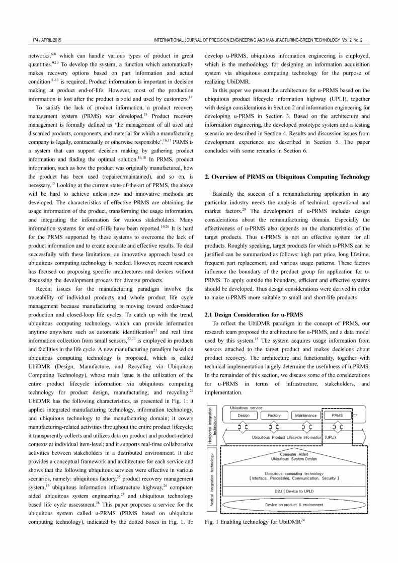
UbiDMR has the following characteristics, as presented in Fig. 1: it
applies integrated manufacturing technology, information technology,
and ubiquitous technology to the manufacturing domain; it covers
manufacturing-related activities throughout the entire product lifecycle;
it transparently collects and utilizes data on product and product-related
contexts at individual item-level; and it supports real-time collaborative
activities between stakeholders in a distributed environment. It also
provides a conceptual framework and architecture for each service and
shows that the following ubiquitous services were effective in various
scenarios, namely: ubiquitous factory,25 product recovery management
system,15 ubiquitous information infrastructure highway,26 computer-
aided ubiquitous system engineering,27 and ubiquitous technology
based life cycle assessment.28 This paper proposes a service for the
ubiquitous system called u-PRMS (PRMS based on ubiquitous
computing technology), indicated by the dotted boxes in Fig. 1. To
develop u-PRMS, ubiquitous information engineering is employed,
which is the methodology for designing an information acquisition
system via ubiquitous computing technology for the purpose of
realizing UbiDMR.
In this paper we present the architecture for u-PRMS based on the
ubiquitous product lifecycle information highway (UPLI), together
with design considerations in Section 2 and information engineering for
developing u-PRMS in Section 3. Based on the architecture and
information engineering, the developed prototype system and a testing
scenario are described in Section 4. Results and discussion issues from
development experience are described in Section 5. The paper
concludes with some remarks in Section 6.
2. Overview of PRMS on Ubiquitous Computing Technology
Basically the success of a remanufacturing application in any
particular industry needs the analysis of technical, operational and
market factors.29 The development of u-PRMS includes design
considerations about the remanufacturing domain. Especially the
effectiveness of u-PRMS also depends on the characteristics of the
target products. Thus u-PRMS is not an effective system for all
products. Roughly speaking, target products for which u-PRMS can be
justified can be summarized as follows: high part price, long lifetime,
frequent part replacement, and various usage patterns. These factors
influence the boundary of the product group for application for u-
PRMS. To apply outside the boundary, efficient and effective systems
should be developed. Thus design considerations were derived in order
to make u-PRMS more suitable to small and short-life products
2.1 Design Consideration for u-PRMS
To reflect the UbiDMR paradigm in the concept of PRMS, our
research team proposed the architecture for u-PRMS, and a data model
used by this system.15 The system acquires usage information from
sensors attached to the target product and makes decisions about
product recovery. The architecture and functionality, together with
technical implementation largely determine the usefulness of u-PRMS.
In the remainder of this section, we discuss some of the considerations
for u-PRMS in terms of infrastructure, stakeholders, and
implementation.
Fig. 1 Enabling technology for UbiDMR24
INTERNATIONAL JOURNAL OF PRECISION ENGINEERING AND MANUFACTURING-GREEN TECHNOLOGY Vol. 2, No. 2 APRIL 2015 / 175
The perspective of infrastructure
1) Design consideration #1 - Information access infrastructure: To
obtain product information from various databases of stakeholders the
PRMS infrastructure must be established.
2) Design consideration #2 - Internet interface: PRMS should
provide an interface to access the databases of every stakeholder in the
product lifestyle via the internet.
3) Design consideration #3 - XML (eXtensible Markup Language) and
ontology support: To enable querying, updating, and integrating target
product data in PRMS, the information should be delivered as the data
format representing relevant expertise extensively used by each stakeholder.
4) Design consideration #4 - Use of standardized information: The
products dealt with by PRMS should not be limited by physical area
and information domain. For interoperability and domain-free usage
PRMS should be able to interface with international standards.30-32
5) Design consideration #5 - Integration capability: Information
obtained from various sources, such as databases of stakeholders and
embedded devices, needs to be combined to produce high-level
information for remanufacturing and recycling. This is a key function
determining the performance of PRMS.
6) Design consideration #6 - Comprehensiveness of information
contents: Information provided by PRMS should be comprehensive so that
recycling and remanufacturing can be performed accurately and optimally.
The perspective of implementation
7) Design consideration #7 - Comprehensiveness of information
gathering ubiquitous device: PRMS should be able to read information
from various devices embedded in the product, including radio
frequency identification (RFID), small sensors, etc.
8) Design consideration #8 - Multi-tasking capability: Tasks for assembly
and disassembly during remanufacturing or recycling require information
about multiple components. For the sake of task efficiency PRMS should have
multi-tasking capability to provide multiple product information for users.
9) Design consideration #9 - Generation of disassembly
information: If disassembly information is not available from the
product information, then PRMS should generate the disassembly
sequence to replace the bad part(s) during remanufacturing. The
sequence can be represented by AND/OR graph and transition matrix.33
10) Design consideration #10 - Variety of human-computer
interface devices: Human operators may access PRMS via various
devices in various situations
The stakeholder perspective
11) Design consideration #11 - Target products: Considering the
target product group is the first step in designing PRMS. This
determines the data model of information gathered from stakeholders
and the recovery decision algorithm.
12) Design consideration #12 - Knowledge-based functionality:
The purpose of PRMS is, in essence, to provide sufficient information
so that the user can make the best decisions. This capability will be
very useful for non-expert users. Just to support recovery decisions, this
functionality is not mandatory.
13) Design consideration #13 - Virtual simulation: Like computer-
aided manufacturing software, PRMS should display virtual operations
to identify any possible errors before execution by remanufacturing.
14) Design consideration #14 - Feedback to the original
manufacturer: To close the product lifecycle loop, all the relevant
information observed in the recycling process via PRMS should be fed
back to the original manufacturer for redesigning the original product.
Note that this is also a crucial factor for eco-design considering the
environmental aspect in the product development stage.34
2.2 Generic Architecture
The generic architecture is derived from the design considerations
described above. These considerations are utilized to design the
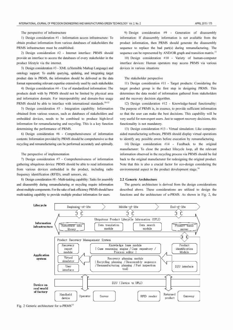
functions and the architecture of u-PRMS. As shown in Fig. 2, the
Fig. 2 Generic architecture for u-PRMS15
176 / APRIL 2015 INTERNATIONAL JOURNAL OF PRECISION ENGINEERING AND MANUFACTURING-GREEN TECHNOLOGY Vol. 2, No. 2
generic architecture is composed of four layers: life cycle, information
infrastructure, application system, usage environment in the real world.
The lifecycle layer means the status of the product from the perspective
of lifecycle: beginning-of-life, middle-of-life, and end-of-life. The
second layer, information infrastructure, is the infrastructure where the
information is transformed, exchanged, and retrieved by the various
stakeholders. The UPLI (Ubiquitous Product Lifecycle Information)
network explained below belongs to this layer. The third layer,
application system, consists of the various systems used by the
stakeholder for the purpose of lifecycle activity by interfacing with the
information infrastructure. PRMS belongs to this layer. The fourth
layer, real world device, is used to acquire/aggregate the product
information via sensors, RFID, sensor network. Since the PRMS is
closely related to the information infrastructure and application layers,
the details of the modules in these two layers are given below.
Information infrastructure (UPLI)
1) Product name server: This server stores the information about
linking and binding the product identification and its corresponding
internet protocol address indicating stakeholder databases. This
explains why PRMS is required to have an interfacing capability with
the UPLI based on design considerations #1 and #2 given in Section
2.1.
2) Data search module: This module searches product information
from the databases on the internet with the internet protocol address
given by the product name server. For the sake of speed of PRMS, this
module should search in a simultaneous manner. This complies with
design consideration #8.
3) Data translation module: In general, the data models including
terminology and information hierarchy obtained from databases of
various stakeholders are not consistent and so require translation. For
this purpose, mapping the local data into international standard data
(complies with Design consideration #4) via ontology representation
language such as extensible markup language and web ontology
language is required, complies with Design consideration #3.
4) Reference data library: This library is a database storing the
mapping relationships with local ontology and the international
standard ontology. It should be noted that the reference data library and
product name server should be synchronized in such a way that if an
internet protocol address for a new database of a stakeholder is added
to the product name server, then a local ontology corresponding to the
uniform resource locator should be added to the reference data library
(complies with Design consideration #5). The international standards
for reference data library can be found in ISO 10303-239.32
Product Recovery Management System (PRMS)
5) Product identification module: This module requests product
information from the information infrastructure for the product
identification and stores it in the PRMS database. To increase the
performance of this module, the module should connect to a number of
databases simultaneously (complies with Design consideration #6).
6) D2U (Device-to-UPLI) interface: The D2U interface module
converts information from the D2U to the information for the PRMS
modules. Thus, interfacing capability with various ubiquitous
computing devices is required, as described in Design consideration #7.
7) PRMS database: This database stores all product information
related to its product recovery such as computer-aided design, bill of
material, usage information, previous remanufacturing cases, etc. This
is necessary to satisfy requirements mentioned in many design
considerations, such as #1, #4, and #6.
8) Knowledge base module: This module uses previous cases to
improve the efficiency and accuracy of recovery decisions. This
complies with Design consideration #12.
9) Recovery planning module: This is the main function of PRMS
that the user (e.g., an operator in a remanufacturing facility) can
appreciate. PRMS supports users in the process of remanufacturing.
Each of these modules should interface with the knowledge base
module to provide useful information to the user. In this way,
information can be provided for disassembly, especially for complex
products (complies with Design considerations #9 and #11).
10) Recovery report module: This is for the closed-loop
information interface between the remanufacturer and manufacturer.
This is a key aspect that is emphasized in this paper as a means for
improving the design of the next product generation. To this end, this
module reports information at the end-of-life stage including the recovery
cost and option used, problems occurring at the remanufacturing stage,
and general statistics, such as damage statistics and component failure
rates. This complies with Design consideration #14.
11) Virtual simulator: This module supports users by showing the
planned operation via graphic simulation. This module complies with
Design consideration #13.
12) User interface: This interface provides an interface between
PRMS and user devices. This module complies with Design
consideration #10.
3. Ubiquitous Information Engineering
The customization to target product and adaptation of the generic u-
PRMS architecture is necessary because the characteristics of the
product influence the implementation architecture. This paper shows
how the generic u-PRMS architecture can be applied to a specific
product taking a starter motor as an example. An emphasis is given to
developing a structured method to design the information acquisition
method called ubiquitous information engineering, the vertical column
technology in the technology map of UbiDMR of Fig. 1 for u-PRMS.
Ubiquitous information engineering can be defined as a systematic
approach to designing a ubiquitous information acquisition system,
which is a set of all components acquiring the information needed for
ubiquitous service from Product / Process / Resource / Environment /
User / Organization of the real world over the whole product lifecycle
by various kinds of method in order to provide information to the
stakeholders. Ubiquitous information engineering is also an engineering
approach for information acquisition methods in the UbiDMR
environment and focuses on how to acquire the information to be used
in the ubiquitous service of various stakeholders based on real field
data.35 The ubiquitous service is the application system that is provided
by stakeholders in the product life cycle based on ubiquitous
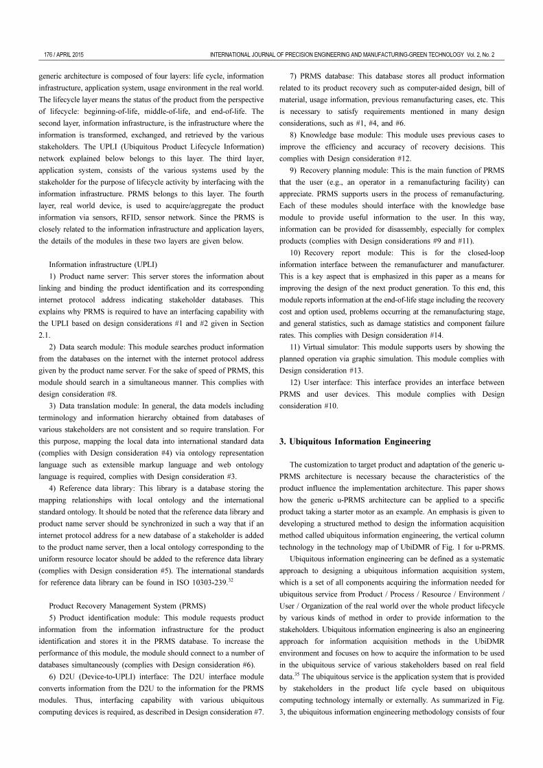
computing technology internally or externally. As summarized in Fig.
3, the ubiquitous information engineering methodology consists of four
INTERNATIONAL JOURNAL OF PRECISION ENGINEERING AND MANUFACTURING-GREEN TECHNOLOGY Vol. 2, No. 2 APRIL 2015 / 177
stages: Objective and use case definition, Requirement analysis,
System design, and Validation and verification.
Note that the stages of this methodology are derived from system
engineering processes used for designing complex systems such as
aircraft, military equipment, and aerospace equipment.36 Ubiquitous
information engineering is derived from the system engineering process
where the outputs are the documents of functions and processes in the
developed system. The function and process of a ubiquitous information
acquisition system are determined by ubiquitous service and the activity
of product life cycle. This section describes the processes.
Since the purpose of the proposed system is to collect the product
information required for the ubiquitous service, the service provided
target product should be determined. To make a decision, the product
type and scope of the service should be known. Standardized systems for
product classification37 are used for the purpose of defining the scope of
services because the products are grouped with considerations about the
industrial characteristics of production, logistics, usage, and disposal.
When the target product is determined, the service provider, its
service, the client of the service should be defined. A service blueprint38 represents the relationship between its provider and its client as well
as the original service process. In the case of u-PRMS, its service is a
support service of remanufacturing guidelines which the manufacturer
provides to remanufacturing factories.
3.1 Stage 1: Objective and Use Case Definition
Objective and use case definition is the stage of defining the
purpose and the usage scenario of the information acquisition system
which will be developed. Objective definition means defining the
purpose of information acquisition. The objective tree method39 or
quality function deployment40 can be used for classifying objectives
into sub-objectives and evaluating the importance of the sub-objectives.
For example, the major objective of the information acquisition system
for u-PRMS is to decide whether each part is reused or recycled. To do
this, the sub-objectives are information collection, information
integration, and identification of part status.
The use case definition involves deriving to-be scenarios including
the activities and information flow of the modules of the information
acquisition system. For example, a possible scenario of u-PRMS is to
collect part status and maintenance history in the usage stage and to
make a decision on the remanufacturing based on collected information
when a product is disposed of. The information output from this stage
concerns objectives and use case of the information acquisition system.
3.2 Stage 2: Requirement Analysis
The second stage is the activity to derive design considerations and
functions and to define data requirements in accordance with the
objectives and use cases defined in the previous stage. Data
requirement describes what data should be captured by the information
acquisition system. Data requirements include the format, range,
memory size, and data collection frequency of the product information
required for the service.
Design consideration means the constraints for designing the
information acquisition system. Design considerations are divided into
the considerations required by the service provider and client,
considerations of information infrastructure exchanging product
information, and considerations of implementing ubiquitous computing
devices in the real world such as contactless identification system (RFID:
Radio Frequency Identification) and location tracking system (RTLS:
Real Time Locating System). In the case of the u-PRMS applied to
vehicles, it is possible to exchange data between the D2U in its engine
and main server regardless of the location of the position of vehicles.
Functional derivation involves deriving necessary functions in order
to carry out the activities in the usage scenario. At this stage functions
for collecting large amounts of data are required to accommodate the
Fig. 3 Procedure of ubiquitous information engineering

178 / APRIL 2015 INTERNATIONAL JOURNAL OF PRECISION ENGINEERING AND MANUFACTURING-GREEN TECHNOLOGY Vol. 2, No. 2
design considerations. The IDEF0 (Integration Definition for Function
Modeling)36 diagram is useful for this functional derivation. In the case
of a D2U of u-PRMS, sensor data collection and wireless
communication are the functions that the D2U should carry out.
3.3 Stage 3: System Design
In the system design, the modules composing the information
acquisition system to satisfy the requirements analyzed in the previous
stage are designed. The composition modules are classified into an
acquisition module, delivery module, storage module, and processing
module from the perspective of the role in usage scenarios. The acquisition
module is a module that collects real world data such as that of products,
the environment, humans, etc. The design criteria for the information
acquisition module are sensor type and attachment location of the sensor.
Selecting the sensor type means finding a sensor that suits the physical
phenomena which should be detected. Determining the attachment location
means finding parts and locations attachable for the selected sensor. For
example, X and Y acceleration sensors are attached to the surface of the
housing to acquire the vibration data of a starter motor.
The delivery module is a module that transmits the data captured by
an acquisition module into data storage such as a memory or a database.
The design criteria are the communication protocol, which is suitable for
the situation of a target product, and the communication device with
selected protocol. When the sensor data inside an engine are collected,
wired cables are suitable because the distance between the data collection
system and sensor is short. However, if the installation of cables for a
sensor is difficult, then a wireless sensor using a short-distance
communication protocol (e.g., IEEE 802.15.4) or wireless local area
network (WLAN) access point is selected for the communication device.
The storage module is a module for storing the collected data. The
design criteria are the location type and the database structure of the
storage. The location types of storage are largely small-size memory
devices inside the product and an information system outside the product.
If the storage capability of the product has not enough space because the
product information is too great, then external database is effective and
efficient. For example, in the case of implementing the usage information
database for construction machinery, a customer relationship
management server or maintenance information system is a location
available for installation of the storage module. Designing a database
structure involves determining the primary key and table criteria.
The processing module uses an algorithm deriving the information
required for service by processing the collected data. The design
criteria are the information processing algorithm, the procedure of
information processing. The operation time and number of operations
can be calculated via the sensor data of the starter motor. The procedure
of information processing is necessary because various algorithms are
conducted sequentially along the information flow. For example, the
failure rate is calculated with the operation time derived from vibration
sensor data. To do this, noise reduction, filtering, operation time
calculation, and lifetime algorithms are typically used sequentially.
The implementation architecture shows acquisition / delivery /
storage / processing modules derived from this system design,
duplications or additional interfaces between modules, and the whole
information flow. This architecture is also an intermediate result of this
design process. In the case of u-PRMS for a starter motor D2U, usage
data collection system, PRMS, and handheld devices are the components
of u-PRMS. Details about these components are given in section 4.
3.4 Stage 4: Verification and Validation
Stage 4 examines whether or not the architecture designed in stage
3 satisfies the requirements of the information acquisition system. The
verification and validation steps examine the performance of the
operating developed prototype with a demonstration scenario derived
from the usage scenario and compensation for the defects that occurred
during the operation. The examination process is to compare the
activities of to-be scenarios with the activities of demonstration
scenarios and to derive the advantage of the prototype. For example, if
a device adopting a low-speed and short-distance communication
protocol (e.g., IEEE 802.15.4) is too slow to transmit the sensor data
of part of the engine, then the designer goes back to stage 2 and should
add new constraints to the design consideration of the information
infrastructure. To reflect a new constraint, a communication device
may be changed to wireless local area network (WLAN) for the
delivery module in stage 3. After it is validated and verified in the next
stage and redesigned, it becomes the final architecture.
4. Prototype Implementation
To verify the validity and effectiveness of the developed methods,
a u-PRMS prototype was developed. The product was chosen based on
the considerations: The salvage process of the machinery is almost a
manual operation requiring high expertise while the remanufacturing
market is well developed. Based on this we selected a part of engine
used in construction machinery, a high demand item in the
remanufacturing market. The salvage process can be improved by the
remanufacturing guidelines for individual machinery provided by u-
PRMS.41 The prototype gives the operator the information required for
remanufacturing these parts.
The service for u-PRMS is the remanufacturing service of
construction machinery. This service is based on real company A, which
remanufactures construction machinery. Company A collects used
machines by paying some price through a dealer, and remanufactures
them. u-PRMS supports the remanufacturing operators by providing the
remanufacturing guidelines for individual products. The information
required for this service includes the final status of parts, disassembly
instructions, and environmental regulations for the products. The scope
of the prototype is the information system acquiring the information
which is called ‘u-PRMS for a starter motor’. This section describes the
development process of u-PRMS for the starter motor.
4.1 Objective and Use Case Definition
The remanufacturing growth of this machinery is limited now.
Refurbishing core parts with high quality is difficult because a
company requires enough experts to conduct manual technical
processes. The survey shows that only companies occupying more than
5% of the market operate remanufacturing services for their own
products. In order to overcome this limitation, expert knowledge is
utilized by gathering usage data and binding it to previous cases.
Therefore the main objective of the prototype is defined as gathering
INTERNATIONAL JOURNAL OF PRECISION ENGINEERING AND MANUFACTURING-GREEN TECHNOLOGY Vol. 2, No. 2 APRIL 2015 / 179
usage data. It also has 5 sub-objectives: identifying individual products,
checking usage conditions, checking part condition, collecting part
history, and delivering the collected data.
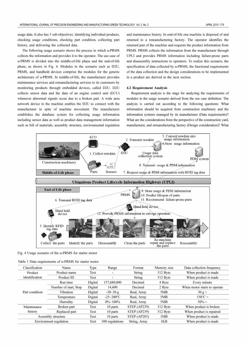
The following usage scenario shows the process in which u-PRMS
collects the information and provides it to the operator. The use case of
u-PRMS is divided into the middle-of-life phase and the end-of-life
phase, as shown in Fig. 4. Modules in the scenario such as D2U,
PRMS, and handheld devices comprise the modules for the generic
architecture of u-PRMS. In middle-of-life, the manufacturer provides
maintenance services and remanufacturing services to its customers by
monitoring products through embedded devices, called D2U. D2U
collects sensor data and the data of an engine control unit (ECU)
whenever abnormal signals occur due to a broken part. A wide area
network device in the machine enables the D2U to connect with the
manufacturer in spite of machine movement. The manufacturer
establishes the database system for collecting usage information
including sensor data as well as product data management information
such as bill of materials, assembly structure, environmental regulation
and maintenance history. In end-of-life one machine is disposed of and
returned to a remanufacturing factory. The operator identifies the
returned part of the machine and requests the product information from
PRMS. PRMS collects the information from the manufacturer through
UPLI and provides PRMS information including failure-prone parts
and disassembly instructions to operators. To realize this scenario, the
specification of data collected by u-PRMS, the functional requirements
of the data collection and the design considerations to be implemented
in a product are derived in the next section.
4.2 Requirement Analysis
Requirement analysis is the stage for analyzing the requirements of
modules in the usage scenario derived from the use case definition. The
analysis is carried out according to the following questions: What
information should be acquired from construction machinery and the
information systems managed by its manufacturer (Data requirements)?
What are the considerations from the perspective of the construction yard,
manufacturer, and remanufacturing factory (Design consideration)? What
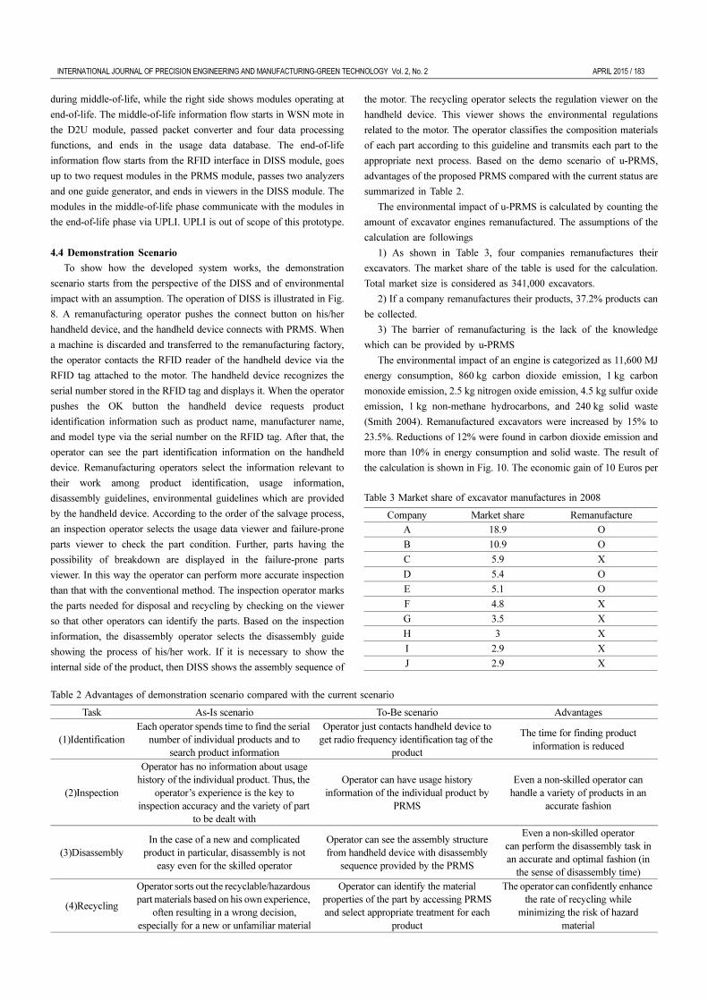
Table 1 Data requirements of u-PRMS for starter motor
Classification Name Type Range Format Memory size Data collection frequency
Product identification
Product name Text - String 512 Byte When product is made
Product ID Text - String 512 Byte When product is made
Part condition
Run time Digital 157,680,000 Decimal 4 Byte Every minuteNumber of start, Stop Digital 14,600 Decimal 2 Byte When motor starts to operate
Vibration Digital -30~30 g Real, Array 5MB 30 g >
Temperature Digital -25~200oC Real, Array 5MB 150oC >Humidity Digital 0%~100% Real, Array 5MB 50% >
Maintenance history
Broken part Text 10 parts STEP (AP239) 512 Byte When product is broken
Replaced part Text 10 parts STEP (AP239) 512 Byte When product is repairedAssembly structure Text 10 parts STEP (AP203) 1MB When product is made
Environment regulation Text 500 regulations String, Array 1KB When product is made
Fig. 4 Usage scenario of the u-PRMS for starter motor

180 / APRIL 2015 INTERNATIONAL JOURNAL OF PRECISION ENGINEERING AND MANUFACTURING-GREEN TECHNOLOGY Vol. 2, No. 2
are the functions necessary for modules of u-PRMS (Functional design)?
Three modules of the u-PRMS for a starter motor acquire data from
a real world situation. Table 1 shows the data requirements. D2U
collects temperature, humidity, and vibration sensor data from the
starter motor while in use. Bearings and electronic parts as well as
insulating materials are weak against high temperature. Bearings and
shafts are corroded by high moisture. Shaft misalignment in the center
of the motor causes motor vibration and the reduction of lifetime for
the bearing. Besides the three sensor data elements, the operation time
and number of uses of the starter motor are derived from the vibration
profile. Product data management stores the assembly information
written in ISO 10303-22442 and regulations relevant to construction
machinery. It also stores the time based maintenance and maintenance
history given by the maintainer of the machinery. The maintenance
history includes dates, broken parts, maintenance method, and replaced
parts. A handheld device equipped with an RFID reader finds the
product model with 8 digits of hex characters stored in the radio
frequency identification tag attached to the motor.
The next step in the design is to accommodate the voices of the
stakeholders participating in the service activities, information
infrastructure, and physical environment where the prototype is
implemented. From the perspective of stakeholders, it is necessary for
the exchange of individual product information items between the
manufacturer and remanufacturer who are the stakeholders of the
service for u-PRMS for a starter motor. The requirement for the
information infrastructure is that it should be possible to connect
between a construction yard and a manufacturer of machinery via long
range wireless communication. The requirements of implementation
are that the size of sensors and memories should be small enough to be
installed in the engine, remanufacturing operators can briefly identify a
number of starter motors, and handheld devices can provide
customized remanufacturing guidelines to the operators such as
inspector, disassembly operator, recycler, etc.
The final step in this stage is to derive what functions are needed to
provide the service described in the usage scenario. The functions,
which each module needs to acquire the data required for product
recovery in the usage scenario of u-PRMS for a starter motor, are
derived. D2U collects sensor data and transmits it via wireless
communication. The usage data collection system processes the data
from wireless communication and stores usage data. Product data
management provides the assembly structure, environmental
regulations, and maintenance history. PRMS generates and transmits
remanufacturing guidelines to operators and stores remanufacturing
history. The handheld device identifies the returned motor and displays
remanufacturing guidelines. The detail design carried out based on
these functions is presented in section 4.3.The second stage is the
activity to derive design considerations and functions and to
4.3 System Design
System design carries out the detail design of D2U, usage data collection
system, PRMS and DISS (Disassembly & inspection support system)
installed in a handheld device to be used by operators as a kind of expert
system. Each module is composed of acquisition module, delivery module,
storage module, and processing module, as described in section 3.3
4.3.1 D2U (Device to UPLI) Module
D2U is a device that collects sensor data and transmits it via
wireless communication. The design criteria are sensor type and
attachment location of the sensor because the collection sensor data
belong to the function of the acquisition module. The sensors of D2U
are humidity sensors, temperature sensors, and accelerometers. Small
sensors are selected due to space limitations in the engine.
Transmitting data via wireless communication is the function of the
delivery module. Its design criteria are communication protocol and the
communication device. D2U uses two types of communication device.
The first device is a wireless sensor network (WSN) mote to exchange
data between the sensor mote and gateway system via low power and
short range communication. It is a small communication device using
personal area network protocol (IEEE 802.15.4). The second device
uses a communication module for wide area network to exchange data
between the gateway system and the usage data collection system. D2U
is composed of a starter motor and sensors and an embedded gateway
system based on two functions as shown in Fig. 5.
4.3.2 Usage Data Collection System Module
The usage data collection system processes the data from wireless
communication and stores usage data. The design criteria are the
information processing algorithm and procedure of information
Fig. 5 Implementation of D2U prototype

INTERNATIONAL JOURNAL OF PRECISION ENGINEERING AND MANUFACTURING-GREEN TECHNOLOGY Vol. 2, No. 2 APRIL 2015 / 181
processing because processing the data is a function of the processing
module. The information processing algorithms of the usage data
collection system are a packet processing algorithm, noise reduction
algorithm, and a filtering algorithm which removes outliers.
The design criteria are location of storage and database structure for
the storage because usage data collection belongs to the function of the
storage module. The external database is determined as a storage
module due to concerns about the amount of sensor data from the
motor over ten years. The database is operated by the manufacturer.
4.3.3 PRMS (Product Recovery Management System) Module
PRMS generates and transmits the remanufacturing guidelines to
operators and stores remanufacturing history. The generated guideline,
which is a function of the processing module, consists of lifetime
prediction/failure rate calculation/part status evaluation/disassembly
sequence/regulation search algorithm. Fig. 6 shows the procedure for
information processing. If the product information is received, then one
procedure includes lifetime, failure rate, and product status, while the
other is composed of generating guidelines for disassembly and
recycling. Two results from two procedures are combined into the
PRMS information, which will be sent to operators and stored in the
PRMS database. The PRMS information is the remanufacturing
guideline, which supports operators.
The PRMS is implemented based on three functions, as shown in
Fig. 7, which consist of an information processing module, operation
communication module, which is a delivery module, and a PRMS
database manager that is a storage module.
4.3.4 DISS (Disassembly & Inspection Support System) Module
DISS identifies motors returned and displays the remanufacturing
guidelines. Identifying returned motors is a function of the acquisition
module. An RFID reader identifying individual RFID tags is attached
to the handheld device for realizing the function of acquisition module.
Operation viewers to display the remanufacturing guidelines are
composed of a product identifier viewer, enabling all operators to
identify each part, usage data viewer, failure-prone parts viewer, which
provides disorder sensor data and broken parts to inspection operator,
disassembly and assembly viewer, and regulation viewer showing the
recycling guideline relevant to parts and operator reporter, as shown in
Fig. 8. The technical issue of DISS implementation is the design
consideration of selecting the user interface device of salvage
operators. The device convenience depends on the type of workspace.Fig. 6 Operation procedure of information processing module
Fig. 7 Operation procedure of PRMS module

182 / APRIL 2015 INTERNATIONAL JOURNAL OF PRECISION ENGINEERING AND MANUFACTURING-GREEN TECHNOLOGY Vol. 2, No. 2
Procedures and details of the operation views are described in the
demonstration scenario in section 4.4.
4.3.5 Implementation Architecture
An implementation architecture is derived from the four mod gules
described in sections 4.3.1 to 4.3.4, as shown in Fig. 9. These four
modules are the minimum elements essentially required for realizing a
genuine u-PRMS. This architecture follows the generic architecture
illustrated in Fig. 2. The information infrastructure layer is UPLI, and
the application system layer consists of a usage data collection system
and PRMS module. The real world layer consists of the D2U module
and the DISS module. The left side contains the modules operating
Fig. 8 DISS screens during demonstration scenario
Fig. 9 Implementation architecture of u-PRMS for starter motor
INTERNATIONAL JOURNAL OF PRECISION ENGINEERING AND MANUFACTURING-GREEN TECHNOLOGY Vol. 2, No. 2 APRIL 2015 / 183
during middle-of-life, while the right side shows modules operating at
end-of-life. The middle-of-life information flow starts in WSN mote in
the D2U module, passed packet converter and four data processing
functions, and ends in the usage data database. The end-of-life
information flow starts from the RFID interface in DISS module, goes
up to two request modules in the PRMS module, passes two analyzers
and one guide generator, and ends in viewers in the DISS module. The
modules in the middle-of-life phase communicate with the modules in
the end-of-life phase via UPLI. UPLI is out of scope of this prototype.
4.4 Demonstration Scenario
To show how the developed system works, the demonstration
scenario starts from the perspective of the DISS and of environmental
impact with an assumption. The operation of DISS is illustrated in Fig.
8. A remanufacturing operator pushes the connect button on his/her
handheld device, and the handheld device connects with PRMS. When
a machine is discarded and transferred to the remanufacturing factory,
the operator contacts the RFID reader of the handheld device via the
RFID tag attached to the motor. The handheld device recognizes the
serial number stored in the RFID tag and displays it. When the operator
pushes the OK button the handheld device requests product
identification information such as product name, manufacturer name,
and model type via the serial number on the RFID tag. After that, the
operator can see the part identification information on the handheld
device. Remanufacturing operators select the information relevant to
their work among product identification, usage information,
disassembly guidelines, environmental guidelines which are provided
by the handheld device. According to the order of the salvage process,
an inspection operator selects the usage data viewer and failure-prone
parts viewer to check the part condition. Further, parts having the
possibility of breakdown are displayed in the failure-prone parts
viewer. In this way the operator can perform more accurate inspection
than that with the conventional method. The inspection operator marks
the parts needed for disposal and recycling by checking on the viewer
so that other operators can identify the parts. Based on the inspection
information, the disassembly operator selects the disassembly guide
showing the process of his/her work. If it is necessary to show the
internal side of the product, then DISS shows the assembly sequence of
the motor. The recycling operator selects the regulation viewer on the
handheld device. This viewer shows the environmental regulations
related to the motor. The operator classifies the composition materials
of each part according to this guideline and transmits each part to the
appropriate next process. Based on the demo scenario of u-PRMS,
advantages of the proposed PRMS compared with the current status are
summarized in Table 2.
The environmental impact of u-PRMS is calculated by counting the
amount of excavator engines remanufactured. The assumptions of the
calculation are followings
1) As shown in Table 3, four companies remanufactures their
excavators. The market share of the table is used for the calculation.
Total market size is considered as 341,000 excavators.
2) If a company remanufactures their products, 37.2% products can
be collected.
3) The barrier of remanufacturing is the lack of the knowledge
which can be provided by u-PRMS
The environmental impact of an engine is categorized as 11,600 MJ
energy consumption, 860 kg carbon dioxide emission, 1 kg carbon
monoxide emission, 2.5 kg nitrogen oxide emission, 4.5 kg sulfur oxide
emission, 1 kg non-methane hydrocarbons, and 240 kg solid waste
(Smith 2004). Remanufactured excavators were increased by 15% to
23.5%. Reductions of 12% were found in carbon dioxide emission and
more than 10% in energy consumption and solid waste. The result of
the calculation is shown in Fig. 10. The economic gain of 10 Euros per
Table 2 Advantages of demonstration scenario compared with the current scenario
Task As-Is scenario To-Be scenario Advantages
(1)IdentificationEach operator spends time to find the serial
number of individual products and to search product information
Operator just contacts handheld device to get radio frequency identification tag of the
product
The time for finding product information is reduced
(2)Inspection
Operator has no information about usage history of the individual product. Thus, the
operator’s experience is the key to inspection accuracy and the variety of part
to be dealt with
Operator can have usage history information of the individual product by
PRMS
Even a non-skilled operator can handle a variety of products in an
accurate fashion
(3)DisassemblyIn the case of a new and complicated
product in particular, disassembly is not easy even for the skilled operator
Operator can see the assembly structure from handheld device with disassembly
sequence provided by the PRMS
Even a non-skilled operatorcan perform the disassembly task in an accurate and optimal fashion (in
the sense of disassembly time)
(4)Recycling
Operator sorts out the recyclable/hazardous part materials based on his own experience,
often resulting in a wrong decision, especially for a new or unfamiliar material
Operator can identify the material properties of the part by accessing PRMS and select appropriate treatment for each
product
The operator can confidently enhance the rate of recycling while
minimizing the risk of hazard material
Table 3 Market share of excavator manufactures in 2008
Company Market share Remanufacture
A 18.9 O
B 10.9 O
C 5.9 X
D 5.4 O
E 5.1 O
F 4.8 X
G 3.5 X
H 3 X
I 2.9 X
J 2.9 X

184 / APRIL 2015 INTERNATIONAL JOURNAL OF PRECISION ENGINEERING AND MANUFACTURING-GREEN TECHNOLOGY Vol. 2, No. 2
kg when calculated versus 1.8 million Euros and scrap metal price of
350 U.S. dollars, you can expect a savings of 16,030,000 U.S. dollars.
Economic benefit 1.8 million Euros for carbon dioxide emission
reduction and 350 US dollars for metal scrap if carbon dioxide
emission certified emission reduction is 10 Euros per kg and scrap
price is 350 dollars per kg. Result findings investigated during the
implementation are discussed in the next section.
5. Discussion
The prototype implementation shows that the introduction of
ubiquitous information engineering for u-PRMS is one of the ways to
overcome the trade-off between information level and equipment cost
occurring from development complexity. Four modules designed in the
system design covered functions required for collecting product
information for recovery decision. It is more efficient that the developer
concentrates on these modules because system design without
predefined basic modules takes a long time. With regard to derivation
of data requirement, the data relevant to part condition influences the
demand for high-priced equipment such as wireless communication,
independent databases, and specialized sensors. Data size and
collection frequency are also strongly related to development cost.
Therefore, these two factors should be optimized before implementing a
system. Furthermore this result means that information content is also as
important as information selection mentioned by Kulkarni et al..20
Development cost can be reduced by using standardized data models
defined by ISO 10303 for collecting assembly information, bills of
material, and repair history from manufacturers and maintainers.
Commercially available modules to handle the standardized data models
have already been developed. According to Simon’s result equipment
cost for implementing specialized devices will decrease.19 Recent
equipment costs for ubiquitous computing are no longer being reduced.
For example, the RFID price of Walmart and the U.S. department of
defense did not change for several years. Efficient system design will be
a successive breakthrough for introducing PRMS.
Other companies starting to remanufacture results in reduction of
environmental impact due to easy to access and use of product
information and actual condition.12 Through supporting u-PRMS
independent companies are able to access the business because they
can handle a greater variety of products. Such a system can realize
securing of greater quantities of products by independent companies.9,10
Tracking systems recording usage history increase the rate of core
retrieval more than 0.372%.4 Also, u-PRMS will be applied to other
construction machinery as well. Therefore, a greater reduction of
environmental impact can be expected from practical application of u-
Fig. 11 Material flow of company a remanufacturing construction machineries
Fig. 10 Analysis results of remanufacturing business

INTERNATIONAL JOURNAL OF PRECISION ENGINEERING AND MANUFACTURING-GREEN TECHNOLOGY Vol. 2, No. 2 APRIL 2015 / 185
PRMS than the results of this research show. From the perspective of
a sustainable society it is worth considering how the developed system
can improve the material flow. For such a purpose, let us consider the
material flow of company A, remanufacturing construction machinery
as shown in Fig. 11. The usefulness of the proposed u-PRMS can be
summarized as follows: The remanufacturers can reduce recovery cost
and waste by the various decision support functions based on accurate
information from the u-PRMS. The errors of the shop floor operator in
the salvage process can also be reduced. Further, the Dealer and Broker
can determine reusable parts accurately from the usage information
from u-PRMS. As well, unnecessary logistic costs caused by wrong
decisions by the Dealer and Broker can be eliminated.
6. Conclusions
In this paper, the following issues are addressed: 1) the necessity of
PRMS, 2) the necessity of ubiquitous computing technology for PRMS,
and 3) the necessity of efficient development methods for u-PRMS. In
conclusion, the use of ubiquitous computing technology is inevitable for
obtaining accurate and live information for products. Then, a generic
architecture for u-PRMS was proposed in a previous publication. A key
issue in developing u-PRMS in practice is how to design an information
acquisition system for u-PRMS. For such a purpose, an information
engineering approach called ubiquitous information engineering for
designing the implementation architecture is developed.
To show the validity and effectiveness of the developed method, a
prototype system has been developed for the remanufacture of a starter
motor in construction machinery. Even if it is a prototype, the core
functionality required for u-PRMS architecture is fully incorporated
through the design process of ubiquitous information engineering. By
the proposed ubiquitous information engineering methodology the
developers of u-PRMS can reduce efforts developing u-PRMS. Also,
the contribution of the u-PRMS to the sustainability of society based on
the material flow in the remanufacturing process in practice is
explained.
The PRMS itself is not the main concern for the current industry as
the remanufacturing market is not very mature. The effort in
developing PRMS may be a burden rather than a benefit economically
because its existence just increased production cost without increase of
product value. Furthermore, developing an advanced PRMS, u-PRMS
may be more burdensome for industry except for special products
required for constantly monitoring appropriate use and remanufacturing
such as military vehicles. As shown, the necessity and effectiveness of
u-PRMS is significant so there must be a method for minimizing efforts
for developing u-PRMS. In this sense, the ubiquitous information
engineering methodology including generic modules that can be used
for general products can be a very powerful approach as the u-PRMS
for specific products can be developed by adding some customized
modules for the specific products under development.
The conclusion based on the research result is as follows. As shown
in the development effect of u-PRMS in construction machinery, from
the environmental perspective the reduction of energy and solid waste
of the whole construction machinery are expected by the application of
u-PRMS. The scrap metal is reduced because the return rate of the
engine core is increased. The energy consumed by manufacturing the
parts from raw material is also reduced. From the industrial perspective
the development of u-PRMS via ubiquitous information engineering
methodology is shown as one of the methods of applying ubiquitous
computing technology to the remanufacturing industry. Future work
includes adding factors of remanufacturing market aspects such as the
price and demand for each part to the remanufacturing guideline of
PRMS and to derive integrated architecture with legacy systems
including enterprise resource planning, product lifecycle management,
and manufacturing execution system. The future work carried out
based on the result contributes application research to enable extension
to various types of machinery through the proposed methodology.
ACKNOWLEDGEMENT
This research was in part supported by the International Research &
Development Program funded by the Ministry of Education, Science
and Technology (MEST) of Korea (Grant number: K21001001621-
10B1300-02910, FY2010), the Eco-Design Graduate School Program
funded by Ministry of Environment of Korea, and the Support Program
for Graduate School of Engineering Mastership by the Korean Ministry
of Knowledge and Economy(MKE).
REFERENCES
1. Thierry, M., Salomon, M., Van Nunen, J., and Van Wassenhove, L.,
“Strategic Issues in Product Recovery Management,” California
Management Review, Vol. 37, No. 2, pp. 114-135, 1995.
2. Gungor, A. and Gupta, S. M., “Issues in Environmentally Conscious
Manufacturing and Product Recovery: A Survey,” Computers &
Industrial Engineering, Vol. 36, No. 4, pp. 811-853, 1999.
3. Kerr, W. and Ryan, C., “Eco-Efficiency Gains from
Remanufacturing: A Case Study of Photocopier Remanufacturing at
Fuji Xerox Australia,” Journal of Cleaner Production, Vol. 9, No. 1,
pp. 75-81, 2001.
4. Smith, V. M. and Keoleian, G. A., “The Value of Remanufactured
Engines: Life-Cycle Environmental and Economic Perspectives,”
Journal of Industrial Ecology, Vol. 8, No. 1-2, pp. 193-221, 2004.
5. Lee, G. B. and Badrul, O., “Integrating Axiomatic Design Principles
into Sustainable Product Development,” Int. J. Precis. Eng. Manuf.-
Green Tech., Vol. 1, No. 2, pp. 107-117, 2014.
6. Matsumoto, M., “Business Frameworks for Sustainable Society: A
Case Study on Reuse Industries in Japan,” Journal of Cleaner
Production, Vol. 17, No. 17, pp. 1547-1555, 2009.
7. Matsumoto, M., “Development of a Simulation Model for Reuse
Businesses and Case Studies in Japan,” Journal of Cleaner
Production, Vol. 18, No. 13, pp. 1284-1299, 2010.
8. Östlin, J., Sundin, E., and Björkman, M., “Importance of Closed-
Loop Supply Chain Relationships for Product Remanufacturing,”

186 / APRIL 2015 INTERNATIONAL JOURNAL OF PRECISION ENGINEERING AND MANUFACTURING-GREEN TECHNOLOGY Vol. 2, No. 2
International Journal of Production Economics, Vol. 115, No. 2, pp.
336-348, 2008.
9. Geyer, R. and Jackson, T., “Supply Loops and Their Constraints:
The Industrial Ecology of Recycling and Reuse,” California
Management Review, Vol. 46, No. 2, pp. 55-73, 2004.
10. Sundin, E., Tang, O., and Mårtén, E., “The Swedish
Remanufacturing Industry: An Overview of Present Status and
Future Potential,” Proc. of the International CIRP Life Cycle
Engineering Seminar, Paper No. BM4 on the LCE-05 CD, 2005.
11. Ilgin, M. A. and Gupta, S. M., “Recovery of Sensor Embedded
Washing Machines using a Multi-Kanban Controlled Disassembly
Line,” Robotics and Computer-Integrated Manufacturing, Vol. 27,
No. 2, pp. 318-334, 2011.
12. Luttropp, C. and Johansson, J., “Improved Recycling with Life
Cycle Information Tagged to the Product,” Journal of Cleaner
Production, Vol. 18, No. 4, pp. 346-354, 2010.
13. Ondemir, O., Ilgin, M. A., and Gupta, S. M., “Optimal End-of-Life
Management in Closed-Loop Supply Chains using RFID and
Sensors,” IEEE Transactions on Industrial Informatics, Vol. 8, No. 3,
pp. 719-728, 2012.
14. Thomas, V., Neckel, W., and Wagner, S., “Information Technology
and Product Lifecycle Management,” Proc. of the IEEE
International Symposium on Electronics and the Environment, pp.
54-57, 1999.
15. Um, J., Yoon, J.-S., and Suh, S.-H., “An Architecture Design with
Data Model for Product Recovery Management Systems,”
Resources, Conservation and Recycling, Vol. 52, No. 10, pp. 1175-
1184, 2008.
16. Krikke, H., Van Harten, A., and Schuur, P., “On a Medium Term
Product Recovery and Disposal Strategy for Durable Assembly
Products,” International Journal of Production Research, Vol. 36,
No. 1, pp. 111-140, 1998.
17. White, C. D., Masanet, E., Rosen, C. M., and Beckman, S. L.,
“Product Recovery with Some Byte: An Overview of Management
Challenges and Environmental Consequences in Reverse
Manufacturing for the Computer Industry,” Journal of Cleaner
Production, Vol. 11, No. 4, pp. 445-458, 2003.
18. Lambert, A. J., “Disassembly Sequencing: A Survey,” International
Journal of Production Research, Vol. 41, No. 16, pp. 3721-3759,
2003.
19. Simon, M., Bee, G., Moor, P., Pu, J.-S., and Xie, C., “Modeling of
the Life Cycle of Products with Data Acquisition Features,”
Computers in Industry, Vol. 45, pp. 111-122, 2001.
20. Kulkarni, A., Parlikad, A., McFarlane, D., and Harrison, M.,
“Networked RFID Systems in Product Recovery Management,”
Proc. of the IEEE International Symposium on Electronics and the
Environment, pp. 66-71, 2005.
21. McFarlane, D., Sarma, S., Chirn, J. L., Wong, C., and Ashton, K.,
“Auto ID Systems and Intelligent Manufacturing Control,”
Engineering Applications of Artificial Intelligence, Vol. 16, No. 4,
pp. 365-376, 2003.
22. Kiritsis, D., Bufardi, A., and Xirouchakis, P., “Research Issues on
Product Lifecycle Management and Information Tracking using
Smart Embedded Systems,” Advanced Engineering Informatics,
Vol. 17, No. 3, pp. 189-202, 2003.
23. Moor, P. R., “Environmental Life Cycle Information Management
and Acquisition for Consumer Products,” http://www.mrg.dmu.ac.
uk/elima/elima (Accessed 29 May 2006)
24. Suh, S.-H., Shin, S.-J., Yoon, J.-S., and Um, J.-M., “UbiDM: A New
Paradigm for Product Design and Manufacturing via Ubiquitous
Computing Technology,” International Journal of Computer
Integrated Manufacturing, Vol. 21, No. 5, pp. 540-549, 2008.
25. Yoon, J.-S., Shin, S.-J., and Suh, S.-H., “A Conceptual Framework
for the Ubiquitous Factory,” International Journal of Production
Research, Vol. 50, No. 8, pp. 2174-2189, 2012.
26. Lee, B.-E. and Suh, S.-H., “An Architecture for Ubiquitous Product
Life Cycle Support System and Its Extension to Machine Tools with
Product Data Model,” The International Journal of Advanced
Manufacturing Technology, Vol. 42, No. 5-6, pp. 606-620, 2009.
27. Jeong, S., Hur, S. M., and Suh, S.-H., “A Conceptual Framework for
Computer-Aided Ubiquitous System Engineering: Architecture and
Prototype,” International Journal of Computer Integrated
Manufacturing, Vol. 22, No. 7, pp. 671-685, 2009.
28. Cha, J.-M. and Suh, S.-H., “Developing a Conceptual Framework
for UT Based LCA,” in: Glocalized Solutions for Sustainability in
Manufacturing, Jürgen, H. and Christoph, H., (Eds.), Springer, pp.
587-592, 2011.
29. Hatcher, G. D., Ijomah, W., and Windmill, J., “Integrating Design for
Remanufacture into the Design Process: The Operational Factors,”
Journal of Cleaner Production, Vol. 39, pp. 200-208, 2013.
30. ISO No. 14649-1, “Industrial Automation Systems and Integration,
Physical Device Control - Data Model for Computerized Numerical
Controllers - Part 1: Overview and Fundamental Principles,” 2003.
31. ISO No. 10303-403, “Industrial Automation Systems and
Integration - Product Data Representation and Exchange - Part 403:
Application Module: AP203 Configuration Controlled 3D Design of
Mechanical Parts and Assemblies,” 2010.
32. ISO No. 10303-239, “Industrial Automation Systems and
Integration - Product Data Representation and Exchange - Part 239:
Application Protocol: Product Life Cycle Support,” 2012.
33. Chiu, M.-C. and Teng, L.-W., “Sustainable Product and Supply
Chain Design Decisions under Uncertainties,” Int. J. Precis. Eng.
Manuf., Vol. 14, No. 11, pp. 1953-1960, 2013.
34. Sundin, E. and Bras, B., “Making Functional Sales Environmentally
and Economically Beneficial through Product Remanufacturing,”
Journal of Cleaner Production, Vol. 13, No. 9, pp. 913-925, 2005.
INTERNATIONAL JOURNAL OF PRECISION ENGINEERING AND MANUFACTURING-GREEN TECHNOLOGY Vol. 2, No. 2 APRIL 2015 / 187
35. Cha, J.-M. and Suh, S.-H., “Conceptual Model for UT-Based Life
Cycle Assessment (u-LCA),” Proc. of the 9th International
Conference on EcoBalance, pp. 408-411, 2010.
36. Leonard, J., “Systems Engineering Fundamentals,” Defense
Acquisition University Press, 2001.
37. Einsporn, T., “eCl@ss - The Leading Classification System,”
Cologne Institute for Business Research Consult Ltd., 2005.
38. Bitner, M. J., Ostrom, A. L., and Morgan, F. N., “Service
Blueprinting: A Practical Technique for Service Innovation,”
California Management Review, Vol. 50, No. 3, pp. 1-24, 2008.
39. Cross, N., “Engineering Design Method,” Wiley, 4th Ed., 2000.
40. Hauser, J. R. and Clausing, D., “The House of Quality,” Harvard
Business Review, Vol. May-June, pp. 63-73, 1988.
41. Jun, H.-B., Cusin, M., Kiritsis, D., and Xirouchakis, P., “A Multi-
Objective Evolutionary Algorithm for EOL Product Recovery
Optimization: Turbocharger Case Study,” International Journal of
Production Research, Vol. 45, No. 18-19, pp. 4573-4594, 2007.
42. ISO No. 10303-224 “Industrial Automation Systems and Integration
- Product Data Representation and Exchange - Part 224: Application
Protocol: Mechanical Product Definition for Process Planning using
Machining Features,” 2006.