
Design Manual NR/GN/CIV/400/04
88
Design Manual NR/GN/CIV/400/04 Maintenance Delivery Units
Transcript of Design Manual NR/GN/CIV/400/04

Design ManualNR/GN/CIV/400/04
Maintenance Delivery Units

Image titleDescription
© Copyright
Image 0.1Anglia Route Maintenance
Loading equipment for site outing

Maintenance Delivery unitsGuidance
NR/GN/CIV/400/04Issued: March 2021
Official 3/88.
Anthony Dewar Professional Head Buildings & Architecture,Technical Authority
Frank Anatole Principal Architect,Buildings & Architecture,Technical Authority
Boaz Yariv
Boaz Yariv
Senior Architect, Technical Authority
Senior Architect, Technical Authority
Revision Information
Version: 1.0Publication Date: March 2021
Description of changes:First Issue
Garry Bimpson Architectural Technologist,Network Rail Design Delivery
Developed by
Katie Donohue Graphic Designer,Network Rail Design Delivery
Name Department or Role
Name Department or Role
Document verification
Disclaimer
In issuing this standard/control document for
its stated purpose, Network Rail Infrastructure
Limited makes no warranties, expressed or
implied, that compliance with all or any standards/
control documents it issues is sufficient on its own
to provide safety or compliance with legislation.
Users are reminded of their own duties under
legislation.
Compliance with a Network Rail standard/control
document does not, of itself, confer immunity from
legal obligations.
Where Network Rail Infrastructure Limited
has granted permission to copy extracts from
Network Rail standards or control documents,
Network Rail Infrastructure Limited accepts no
responsibility for, nor any liability in connection
with, the use of such extracts, or any claims
arising there from.
This disclaimer applies to all forms of media in
which extracts from Network Rail standards and
control documents might be reproduced.
Maintenance Delivery unitsGuidance
NR/GN/CIV/400/04Issued: March 2021
Official 4/88.
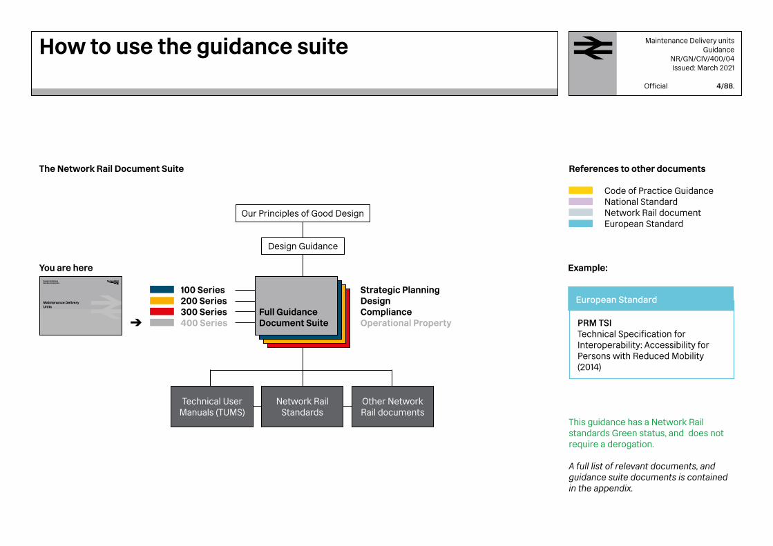
The Network Rail Document Suite
You are here
Code of Practice Guidance National Standard Network Rail document European Standard
Our Principles of Good Design
Design Guidance
Full GuidanceDocument Suite
Technical UserManuals (TUMS)
Network RailStandards
Other Network Rail documents
Strategic Planning Design Compliance Operational Property
Design GuidelinesNR/GN/CIV/400/04
Maintenance Delivery Units
References to other documents
100 Series 200 Series300 Series 400 Series
How to use the guidance suite
Example:
PRM TSITechnical Specification for Interoperability: Accessibility for Persons with Reduced Mobility (2014)
European Standard
A full list of relevant documents, and guidance suite documents is contained in the appendix.
This guidance has a Network Rail standards Green status, and does not require a derogation.

Maintenance Delivery unitsGuidance
NR/GN/CIV/400/04Issued: March 2021
Official 5/88.
Section 1Project Initiation :
Captures the core elements which should be understood and considered on a project, before initiating the design.
Section 3Design and Fit Out :
Describes key elements of design and how they can be applied correctly to provide longevity and integrity.
Section 2Space Planning :
Informs designers of the importance of space planning within an MDU and shows how to best utilise spaces.
Section 4Appendices : Provides additional details, specifications, and Case Studies.
1 2 3 4
IntroductionHow to use this document
Purpose
Network Rail’s role is to deliver a safe and reliable railway infrastructure. The company carefully manages and delivers thousands of projects every year.
MDU stands for Maintenance Delivery Unit. The purpose of an MDU is to provide a physical base for maintaining the railways. MDUs come in many forms and are design specific in nearly all situations. There are a great deal of similarities and good practice thatshould be shared between them that this guidance manual focusses on. This document should assist the project teams designing and delivering new MDUs, to achieve a high standard and to maintain consistent quality across the routes.
This guidance should be used to support new and existing MDU design across the Network Rail estate.
Scope
The intended audience for this Guidance is Designers, Project Managers, Contractors and others involved throughout the stages of MDU projects.
The guidance aims to identify and explain the areas that are unique to MDU buildings. There is an overlap between MDUs and Network Rail's Offices. Guidance on offices is provided in the Workplace DNA NR/GN/CIV/400/05.

Maintenance Delivery unitsGuidance
NR/GN/CIV/400/04Issued: March 2021
Official 6/88.
1
1.11.21.31.41.51.61.7
3
3.13.23.33.43.53.63.73.8
2
2.12.22.32.42.5
4
ABCDEFG
Section 2SPACE PLANNING
Area planningSite OperativesAreas ChecklistExternal Site PlanningFuture Adaptation
Page
3335363738
Section 3DESIGN AND FIT OUT
Quality and RobustnessInternal ProvisionsLook and feelWarehouse ProvisionsLightingHeatingVentilationExternal Areas
Page
4142485455565758
Section 1PROJECT INITIATION
Design PrinciplesRemit DevelopmentProject SustainabilityEnvironmental AssessmentsSite AnalysisCompliance and AssuranceConstructibility Review
Page
911
162021
2530
Section 4APPENDIX
Reference DocumentsCase StudiesRemit development questionsServices Design ParametersTypical drawingsDesign Life TablesGlossary & Acknowledgements
Page
63646972758386
Contents
1Maintenance Delivery UnitsProject Initiation

Image 1.1Front Line Staff
who are based in MDUs

1.1 .1– Design Principles
Network Rail strives for design which is both functional and innovative. This guidance document aims to provide parameters for designers to meet Network Rail’s design expectations. All workplaces should be well considered, putting the end users' requirements at the forefront of the design.
Network Rail prides itself on a number of values which should be represented throughout its workplaces, in order to enable staff to work together in a safe and comfortable environment.
The MDU design intent and concept should be retained as a guiding thread throughout the delivery stages . The facilities should be robust and designed to take the anticipated wear and tear. Spatial requirements should be given due diligence. There is no need for over design and all specification should be means tested against intended use
In sections 1.1.3 to 1.1.10, eight useful principles are highlighted as being key for the development of a robust design brief.
1.1.2 – Inclusive Design
The adoption of Inclusive Design principles helps people to use the new environment safely. Comfort, confidence and convenience should be incorporated into the design of the building to achieve an autonomous safe access to all buildings and car parks.
Diversity and Inclusion should be considered at the outset of every design process. It should also be considered throughout the delivery of projects that are affecting existing facilities. Inclusive Design should create places environments that are user friendly, high-quality, healthy and have a positive impact on all members of a community.
An inclusive approach to design often provides new insights into the way we interact with the environment and opens new opportunities by application of creative problem solving skills. As a public service provider, Network Rail’s property should be designed, built and operated using Inclusive Design principles and in compliance with the Equality Act 2010. Access to the built environment is not simply a question of physical layout, it also relies on good information including signs, lighting,visual contrast and written communication. Applying these principles should enable inclusive environments for Persons with Reduced Mobility (PRM) including persons with hidden disabilities, such as colour blindness or cognitive impairments.
Project Initiation1.1 Design Principles
In order to provide inclusive workplace environments, a Diversity Impact Assessment (DIA) should be carried out for every project. This should demonstrate how duties within the Equalities Act 2010 were considered. The DIA process should highlight any specific requirements should be captured within the design.
A DIA should be carried out as soon as possible and no later than GRIP 2 as the information collated could inform additional design requirements.
It is the Project Managers responsibility to issue the client / end users with a DIA form for them to populate and update throughout the project. The completed form should then be reviewed and signed off by a Network Rail DIA super user.
.
Maintenance Delivery unitsGuidance
NR/GN/CIV/400/04Issued: March 2021
Official 9/88.

Maintenance Delivery unitsGuidance
NR/GN/CIV/400/04Issued: March 2021
Official 10/88.
1.1.3 – Team specific
Every team has specific requirements, methodology and shift patterns that the design remit should capture. Many teams in Network Rail have a process driven role and understanding these processes should effect the design of the MDU's functionality and layout.
1.1.4 – Inclusive
Network Rail support and promote Inclusive design and are committed to create an inclusive environment for staff and visitors in al workplaces. The Diversity Impact Assessment (DIA) process should be followed on all projects as explained in section 1.1.2
1.1.5 – Collaborative
The design should promote spaces in the building that encourage office and front line staff to share spaces and experiences during their daily routines. Provisions should be made for portable IT with charge points, white boards, notice boards and magnetic walls for pinning up notes.
1.1.6 – Organised
The operation of the site requires rationalisation and planning. A one waysystem is preferred as a safe method of moving around the site. This approach should also extend to the internal design keeping activities clash free.
Project Initiation1.1 Design Principles
1.1.7 – Safe Design
MDU Sites can be dangerous places with heavy plant machinery, dangerous substances and vehicular movements. The designer should eliminate, minimise or mitigate the inherent risks. Well thought out walking routes and safe separation of risky activities wherever possible.
1.1.8 – Secure
The design for control of access to and from the site, the stores and the main building should be given thought from the outset. . A robust method of security control should be considered as part of the design input that should be validated by the building operator.
1.1.9 – Efficient
Efficient use of space to reduce the footprint of new and existing buildings wherever possible is always encouraged. For example analysing shift patterns and holiday periods could reduce the size requirement for a mess area considerably.
1.1.10 – Enhancing
Overall a new MDU should represent an improvement over the existing facilities that it is replacing. Ideally this should be achieved by the quality of the design. The designer should also feel comfortable to challenge the project aspirations if they seem to be too low.

Figure 1.1.MDU Classification
Maintenance Delivery unitsGuidance
NR/GN/CIV/400/04Issued: March 2021
Official 11/88.
1.2.1 – Classification by Size
MDUs can come in a range of sizes depending on their location and the services which operate out of them and are defined primarily on staff numbers, teams and overall operations. For simplicity, the document refers to them as small, medium and large.
1.2.2 – Small sized MDU
Small sites have basic facilities and can be on industrial land or adjacent to railway sidings land with minimal storage facilities. The number of staff is typically up to 45 persons.
There could sometimes be a requirement for external exposed storage of components. These sites tend to be secured with a palisade fence and can sometimes be operational 24 hours,. Notably these sites are usually more of a drop-in facility.
1.2.3 – Medium sized MDU
Medium sized sites have a larger number of staff, typically up to 150, utilising the site with their own separate facilities and storage areas, alongside multiple temporary accommodation units and sometimes permanent or more established stores.
These sites historically tend to be sporadic in layout as they have been adapted over many years with different team requirements changing as railway projects are started and completed.
In a medium size MDU there is often the need for office staff, as well as front line staff, who have different requirements. Rationalisation is a key priority when developing these sites to improve efficiencies and site safety.
There could also be an increased requirement for parking both for staff and site-based vehicles. These sites are typically operated 24 hours a day and receive deliveries to site, possibly by Heavy Goods Vehicles.
1.2.4– Large sized MDU
The number of differing activities at these sites can make them complicated. Typically, they demonstrate a permanent dedicated large store facility which is used to feed the Medium and Small sized MDUs. The store should be split between both external and internal stores and accommodate many different teams.
Individual teams are likely to have their own separate facilities with some shared areas i.e. mess rooms or break out areas. The size of rooms and facilities is determined by the number of staff the MDU should facilitate and the activities which could be undertaken.
Large MDUs can utilise a great range of vehicles for use with both deliveries and maintenance on the railway, therefore parking is a key consideration. Security is also a priority where palisade fencing and controlled access is in place.
STORAGE
WAREHOUSESTORES
STORES
Large sized MDU
Medium sized MDU
Small sized MDU
Project Initiation1.2 Remit development

1.2.5 – MDU Operations
Network Rail MDUs have varying operational requirements. Running the railway means lots of teams and coordination is required across the route.
MDUs are typically structured as shown on figure 1.2. The teams operating from these locations could vary. Basic team profiles can be viewed in section 1.2.7. The purpose of these profiles are to demonstrate the depth of roles and jobs that work together to keep the railway operational for passengers and freight. In addition to the front line maintenance teams, each site could have office based administration teams who assist the teams in coordinating projects, incident response and maintenance. These may sit alongside the Route maintenance teams who are responsible for the management of railway assets.
Staff consultation should capture all the team and sub-team requirements to inform the final remit.
A number of potential questions and pointers have been identified in Appendix C, which should initiate the discussion. These should assist in making the design remit robust before designs are initiated. When something happens or requires remedial attention
(Railway incidents, projects or maintenance), this is reported across a geographical area
to the maintenance teams.
Large MDU – Multiple teams and staff members. Both front line and office staff located here.
Medium MDU – Sometimes fed equipment and materials from the large store MDUs, act as satellite MDUs and are located sporadically to cover the whole network.
Small MDU – Used as satellite locations and sometimes based very remotely with specialist teams based there.
Figure 1.2.MDU Operation
Maintenance Delivery unitsGuidance
NR/GN/CIV/400/04Issued: March 2021
Official 12/88.
STORAGE
WAREHOUSESTORES
STORES
Project Initiation1.2 Remit Development

1.2.6 – Prefabricated Units
Although there is a history of using prefabricated units for MDUs in the past, they are generally not deemed to represent good value. The advantages and disadvantages of using prefabricated units should be determined at an early stage and can affect the choice of site.
The design life of a prefabricated unit is limited and this should be considered in the whole life cost analysis and also within the sustainability assessment. Network Rail prefers the use of permanent structures that have been whole life costed. Good quality staff accommodation and welfare facilities also demonstrate an investment in the workforce. However, there are situations where a prefabricated unit is necessary and a decision to go down this route could be justified if any of the following is a prime consideration :
→ The unit might be relocated between sites. → Severe site restrictions prohibit alternative
construction methods. → A temporary building is required which would
allow less stringent conditions (the Building Regulations definition of temporary is no more than 28 days).
The MDU should comply with Building Regulations Approved Document M (Access and Facilities for Disabled People) and the following sections of Approved Document B (Fire Safety of the Building Regulations):
→ B1 - Means of warning and escape (Network Rail Fire Engineer to advise)
→ B2 – Internal fire spread of linings → B3 – Internal fire spread of structure → B4 – External fire spread → B5 – Access facilities for the fire service
(Network Rail Fire Engineer to advise)
Sections B2, B3 and B4 can be most easily demonstrated if they are British Board of Agreement certified. These specifications come at a cost and the notion that the prefabricated units are cheap is a misconception.
However prefabricated units can be the right solution for storage of materials and materials that are of a transitory nature.
Project Initiation1.2 Remit Development
Maintenance Delivery unitsGuidance
NR/GN/CIV/400/04Issued: March 2021
Official 13/88.
Image 1.2Compound in Mercier House, Derby Example of prefabricated storage units

Electrification & Plant (E&P)
Look after substation plant rooms and high voltage supplies in various locations.
1.2.7 – Variety of Teams that might use MDUs
Mobile Operations Manager (MOM)
Operations function, like a first responder to all train delaying incidents from vandalism to suicides.
Track
Maintain the rails, sleepers, ballast and earthworks.
Ultrasonic
Check for flaws inside of the rails to enable rail to be maintained before it causes disruption to passengers.
Lubricators
Use track-side machines to stop the rail from squealing, this decreases the wear on the rails.
Off-track
Looks after all drainage, vegetation, level crossing and highway fencing.
Signal & Telecoms (S&T)
Maintain all signalling equipment from the signal level to the red lights and point controls.
Welding & Grinding (W&G)
Weld rail together and re-profile the rail including switches (points).
Works Delivery
Various disciplines, Buildings, E&P, Permanent Way, OLE,Off Track, renewals and services
Maintenance
Maintain the infrastructure to run the trains on.
Overhead Lines Equipment (OLE)
Look after all of the overhead line electrical equipment to keep trains moving.
Telecoms
Maintain all telecoms equipment in the signalling centres and Rail Operating Centres, including all cabling.
Project Initiation1.2 Remit Development
Maintenance Delivery unitsGuidance
NR/GN/CIV/400/04Issued: March 2021
Official 14/88.

1.2.8 – Toilet and Washing Facilities
Network Rail aims to provide excellent workplaces in order to obtain and retain staff long term. All MDUs should provide appropriate and adequate facilities for both males and females within the workplace, which also includes an allowance for future recruitment and expansion.
Figure 1.3 gives an example on how toilet and washing facilities can be split on the assumption (to be modified at every location) that Office and Site workers are equally split. 'Office staff' are permanently located in the building and 'Front Line staff' are generally maintenance and front line workers who could work across several sites.
The Male, Female and Accessible split for toilet facilities should also align with 'The workplace regulations 1992', published by HSE: www.hse.gov.uk.
Once the requirements for any particular MDU are agreed, the layout should be developed with flexibility in mind to allow for future staff ratio changes.
Total Staff (100%) Office staff (50%)
Male Male
Male
Male
Male
Female Female
Female
Female
Female
Small MDU – max 45
50% 80%
40%
31 11
1 1
18
9
204
97
78
6 6
37
3 3
126
60
60
30
50% 20%
5%
14 11 5
1
111
40 % of Front line staff
(Minimum 5 %Passive provision for Female Front Line staff)
53
79
38
32
8
15
4
Large MDU – 315
Medium MDU – max 150
Front Line staff (50%)
MDU size
Showers
Project Initiation1.2 Remit Development
Figure 1.3.Male and Female Toilet and Shower facilities
Male Female
10
66
33
2
14
7
Maintenance Delivery unitsGuidance
NR/GN/CIV/400/04Issued: March 2021
Official 15/88.

Maintenance Delivery unitsGuidance
NR/GN/CIV/400/04Issued: March 2021
Official 16/88.
1.3.1 - Sustainable Development
Sustainable construction aims to meet present day requirements without compromising the ability of future generations. It incorporates elements of Economic efficiency, Environmental performance and Social responsibility.
The importance of project sustainability can be directly correlated with the success of the overall scheme, both in the short and long term. Each of the three sustainable elements should be considered equally.
These three elements are Environment, Social and Economic sustainability. Figures 1.4, 1.5 and 1.6 give an indication of how these three elements can be interlinked and where overlapping areas can be highlighted. These links should all contribute towards the overall ‘Sustainable development’ on a scheme.
1.3.2 – Economic Sustainability
Economic sustainability goes beyond project costs, construction cost and even whole life costings. The main goal of economic sustainability is to analyse the value of every aspect of a project, maximising economic viability based on past, present and future aspirations. However, economic decisions should not hinder functionality, environmental sustainability and future operations of the business.
Economic / Environmental → Reduction in energy consumption and costs → Sustainable sources of energy generation → Re-use and re-purpose of existing site
elements/structures. → Down-cycle, refurbish and re-use before
purchasing new.
Economic / Social → Whole life costings → Maintenance costs → Staff productivity → Design for future expansion → Engage with local supply chains
Economic → Project costs → Construction costs → Procurement routes
Project Initiation1.3 Project Sustainability
Economic sustainability aspirations are:
→ Reduction in energy consumption → Enables business efficiencies through design → Whole life costed building → Reduce maintenance where possible → Future proof designs → Increased staff productivity → Engagement with supply chain → Procurement routes followed
EconomicSufficient economy
SocialNurturing community
EnvironmentalA viable, natural
environment
Equitable social environment
Sustainable, natural and
built environment
Sustainable economic
development
SUSTAINABLE DEVELOPMENT
Figure 1.4.Economic Sustainability

Maintenance Delivery unitsGuidance
NR/GN/CIV/400/04Issued: March 2021
Official 17/88.
1.3.3 – Social Sustainability
Putting Network Rail’s employees at the forefront of every project is key to a successful project. However, it is not sufficient to only create an inclusive and safe environment. Network Rail’s workers increasingly spend more of their time indoors which places increasing responsibility to design buildings which counteract the negative effect of such exposure, for example; Sick building syndrome.
By incorporating particular design strategies projects can counteract these negative effects. For example, re-linking to nature, fulfilling basic human requirements i.e. natural daylight and fresh air, manually controllable environments and reducing internal toxins, are best practise design principles expected from all projects.
Non-hierarchical open plan collaborative work environments enable better management and the design of separate offices for management within MDUs is discouraged, unless they are for justified for security reasons.
Social Sustainability aspirations are:
→ Staff retention and loyalty → Increased productivity → Access for all → Increased morale and well-being across staff → Reduction in sick days → Easier to manage and operate
Project Initiation1.3 Project Sustainability
Social / Environmental → Staff retention and loyalty → Improved staff mental well-being → Reduction in sick days
Social / Economic → Connections to local communities → Connections to local businesses → Reduction in operation management → Increased productivity → Retention of railway knowledge
Social → Access for all → Improve safe systems of work
EconomicSufficient economy
SocialNurturing community
EnvironmentalA viable, natural
environment
Equitable social environment
Sustainable, natural and
built environment
Sustainable economic
development
SUSTAINABLE DEVELOPMENT
Figure 1.5.Social Sustainability
Maintenance Delivery unitsGuidance
NR/GN/CIV/400/04Issued: March 2021
Official 18/88.
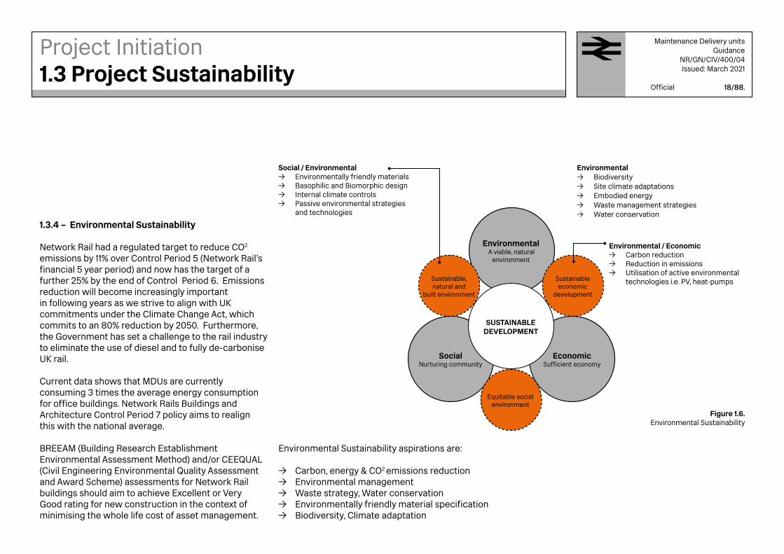
1.3.4 – Environmental Sustainability
Network Rail had a regulated target to reduce CO2
emissions by 11% over Control Period 5 (Network Rail's financial 5 year period) and now has the target of a further 25% by the end of Control Period 6. Emissions reduction will become increasingly important in following years as we strive to align with UK commitments under the Climate Change Act, which commits to an 80% reduction by 2050. Furthermore, the Government has set a challenge to the rail industry to eliminate the use of diesel and to fully de-carbonise UK rail.
Current data shows that MDUs are currently consuming 3 times the average energy consumption for office buildings. Network Rails Buildings and Architecture Control Period 7 policy aims to realign this with the national average.
BREEAM (Building Research Establishment Environmental Assessment Method) and/or CEEQUAL (Civil Engineering Environmental Quality Assessment and Award Scheme) assessments for Network Rail buildings should aim to achieve Excellent or Very Good rating for new construction in the context of minimising the whole life cost of asset management.
Project Initiation1.3 Project Sustainability
Environmental Sustainability aspirations are:
→ Carbon, energy & CO2 emissions reduction → Environmental management → Waste strategy, Water conservation → Environmentally friendly material specification → Biodiversity, Climate adaptation
Environmental → Biodiversity → Site climate adaptations → Embodied energy → Waste management strategies → Water conservation
Social / Environmental → Environmentally friendly materials → Basophilic and Biomorphic design → Internal climate controls → Passive environmental strategies
and technologies
Environmental / Economic → Carbon reduction → Reduction in emissions → Utilisation of active environmental
technologies i.e. PV, heat-pumps
EconomicSufficient economy
SocialNurturing community
EnvironmentalA viable, natural
environment
Equitable social environment
Sustainable, natural and
built environment
Sustainable economic
development
SUSTAINABLE DEVELOPMENT
Figure 1.6.Environmental Sustainability

1.3.5 – Sustainable Design
The current global trend of environmental design has been fixated on high-tech active technologies such as photovoltaic panels (PV), heat pumps, active façades, grey water harvesting and more. Design teams should not rely solely on active technologies to make a project sustainable but as an enhancement tool. Most active technologies have specific requirements, they are not always compatible with other active systems and many have negative side affects. In addition, active environmental systems can be expensive to maintain and install as they require specialist installation.
The RSSB (Rail Safety and Standards Board) has developed the Rail Carbon Tool to enable Calculation and analysis of the carbon footprints of UK rail projects and activities; This tool should assist in identifying and assessing alternative low carbon options and selecting low carbon solutions
All projects should, as a minimum, use passive environmental strategies derived from site analysis as a basis. This ethos should carry forward into the detailed design with materials, detailing and finalised designs reflecting Network Rail's sustainable design aspirations. As part of the Form NR/L2/CIV/003/F004 the designer should submit a sustainability statement to demonstrate that the aspirations listed above are addressed by the design.
Project Initiation1.3 Project Sustainability
1.3.6– Passive provisions
On a new build project preference should be given to passive provisions of environmental comfort that do not require energy input.
The potential for natural ventilation of the building should be maximised by providing windows and roof lights that can open.
Daylight utilisation should be maximised using the building form, glazing and light re-direction elements. Solar shading could be used to minimise overheating on south facing glazing.
Locating service and circulation areas on the north and east elevations helps to insulate the interior , freeing the south and west elevations to harvest solar energy.
Image 1.3Internal plants to improve wellbeiing, Edinburgh MDU
Maintenance Delivery unitsGuidance
NR/GN/CIV/400/04Issued: March 2021
Official 19/88.
Further information:networkrail.co.uk/who-we-are/sustainable-development/
Network Rail website

1.4.1 – Environmental Impact Assessment
Environmental Impact Assessment (EIA) can be required by the local authority in cases where the MDU is subject to a planning application. Network Rail already has in place its own Assessment requirements for the environment and they could be used to inform the EIA in cases where it is required.
The EIA should demonstrate how the impact of the new MDU on the environment can be minimised. It allows the environmental knowledge to influence the design and delivery of the project. A good understanding of the site should inform the Environment Impact Assessment reports and Environment Management Plan to facilitate a sustainable development.
An EIA could be completed by the client team. Consultants can also be nominated to assist with this process if required. The assessment is a live document and should be updated throughout the project process.
1.4.1 – Network Rail's Assessments
The standard NR/L2/ENV/015 identifies Building Research Establishment Environmental Assessment Method (BREEAM) and Civil Engineering Environmental Quality Assessment and Award Scheme (CEEQUAL) as potential independent certifiable environmental assessment methodologies. However for MDU fit-out the Royal Institute of Chartered Surveyors SKA assessment tool also provides a suitable third party independent environmental assessment to evidence carbon reduction objectives.
Figure 1.7 provides the targets that should be achieved by Network Rail projects using the available assessment tools.
Figure 1.7.Network Rail's Environmental Assessment Targets
Points of reference could include :
→ Ecology → Water courses → Noise → Waste → Landscape → Biodiversity → Water → Energy → Traffic
Maintenance Delivery unitsGuidance
NR/GN/CIV/400/04Issued: March 2021
Official 20/88.
Project Initiation1.4 Environmental Assessments

1.5.1 – Site constraints
An understanding of the site constraints should determine the design and establish the viability of the site for the project. The constraints should be highlighted in the risk register that is prepared for the feasibility study.
Key items to consider are:
→ Site boundaries → Vehicular Access → Site levels → Way leaves* → Surrounding context → Local highways → Planning constraints → Proximity to the railway → Water course → Flood risk → Historic land use and listings
* A way leave is a right of way granted by a landowner. One example could be a site which contains an electrical box, the Electrical company Engineers require 24/7 access to this in case of failure or any routine maintenance.
For every project, the project team should visit site in order to grasp the location that they are designing for. Sections 1.5.2 to 1.5.12 explain some key areas that should be considered, but the list is not exhaustive.
1.5.2 – Land ownership
In some situations, Network Rail does not own the land of a site which is being considered and may potentially be required to purchase This could have an impact on budget, programme and pose potential project risks which should be captured at early stages.
1.5.3 – History
Site history can provide relevant context to inform elements of the design. Additional provision could be generated as a result of the history of the site.It is important to identify any heritage constraints or advantages of the site.
1.5.4 – Context
Although surrounding areas and streets, roads, alleys, walkways are typically not likely to change during the project, they should be studied and understood as a way of accessing the site during construction and in operation.
1.5.5 – Natural features
The building position and orientation should be considered as part of the site contours, drainage, flood risk areas, ground cover and texture, soil conditions and surrounding nature.
1.5.6 – Geotechnical Analysis
A significant percentage of construction cost and risk is determined by the ground conditions. A geotechnical survey of the site should be undertaken to identify risks prior to the feasibility study of the scheme.Checks could include and are not limited to:
→ Coal board → Mine workings from Utility Services → Strata levels → Permeability → Services → Water courses → Water tables → Site levels
1.5.7 – Contamination
The characteristics of the land should be established early in the feasibility process. Much of Network Rail land has an industrial past with a high likelihood of contamination from harmful toxins and materials. Dealing with site contaminates can be a significant cost for projects and should be highlighted as early as possible so that it can be avoided if possible.
1.5.8 – Utilities
Information on utilities should be obtained as soon as possible to inform the feasibility study and the
Maintenance Delivery unitsGuidance
NR/GN/CIV/400/04Issued: March 2021
Official 21/88.
Project Initiation1.5 Site Analysis
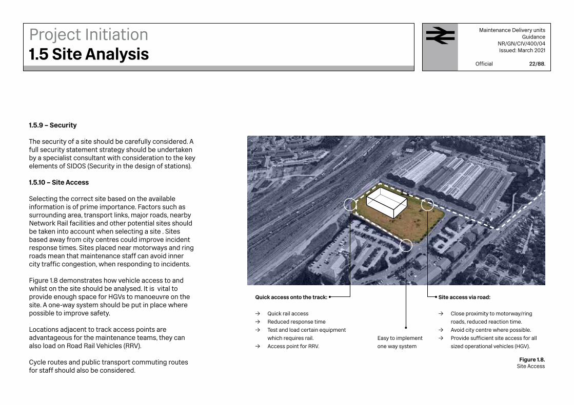
1.5.9 – Security
The security of a site should be carefully considered. A full security statement strategy should be undertaken by a specialist consultant with consideration to the key elements of SIDOS (Security in the design of stations).
1.5.10 – Site Access
Selecting the correct site based on the available information is of prime importance. Factors such as surrounding area, transport links, major roads, nearby Network Rail facilities and other potential sites should be taken into account when selecting a site . Sites based away from city centres could improve incident response times. Sites placed near motorways and ring roads mean that maintenance staff can avoid inner city traffic congestion, when responding to incidents.
Figure 1.8 demonstrates how vehicle access to and whilst on the site should be analysed. It is vital to provide enough space for HGVs to manoeuvre on the site. A one-way system should be put in place where possible to improve safety.
Locations adjacent to track access points are advantageous for the maintenance teams, they can also load on Road Rail Vehicles (RRV).
Cycle routes and public transport commuting routes for staff should also be considered.
Easy to implement
one way system
Site access via road:
→ Close proximity to motorway/ring
roads, reduced reaction time.
→ Avoid city centre where possible.
→ Provide sufficient site access for all
sized operational vehicles (HGV).
Quick access onto the track:
→ Quick rail access
→ Reduced response time
→ Test and load certain equipment
which requires rail.
→ Access point for RRV.
Figure 1.8.Site Access
Maintenance Delivery unitsGuidance
NR/GN/CIV/400/04Issued: March 2021
Official 22/88.
Project Initiation1.5 Site Analysis

1.5.11 – Effect on Local Surroundings
As explained in Figure 1.9, context is a key factor in the design. Deliveries with HGV vehicles are common in MDUs. The effect of site noise and traffic on Network Rail’s neighbours should be considered. The sites may be in a conservation area or have historic buildings on them with the possibility of heritage listings. The designer should always look beyond the boundary of the site and remit.
Background checks and thorough site research should eliminate the likelihood that problems will occur further into the project programme.
Key items to consider are:
→ Listed buildings → Heritage sites → Conservation areas → Future developments in this area → Site access (neighbours affected) → Other Network Rail sites within the area Residential areas
→ Noise from HGV
→ Interruptions and complaints likely
→ Smaller roads, not as wide for access
Existing MDU → Duplication of services in
similar area could leave other
areas with less available
services.
→ Opportunity to share locations
and facilities.
Existing railway → If the site is vacant
when all surroundings
are developed it could
suggest contamination or
issues, therefore thorough
research is required.Figure 1.9.
Context and Impact
Maintenance Delivery unitsGuidance
NR/GN/CIV/400/04Issued: March 2021
Official 23/88.
Project Initiation1.5 Site Analysis

1.5.12 – Sun Path Analysis
Understanding the impact of natural light on architectural space is of prime importance for Architects. This understanding includes knowledge of the sun and its position relative to a geographic location.
Building orientation is vital in both the efficient heating and cooling of the building along with window positions and the location of any Solar panel positions. The orientation of the building should aim to maximise the potential for passive environmental measures, described in section 1.3.6.
Sun path analysis, as shown in Figure 10, should be considered as a way of increasing the energy efficiency of MDUs. Solar gains can benefit Network Rail in reducing overall carbon footprint due to using less energy to heat and cool the building. One way of implementing this is through the use of Solar Panels, therefore the positioning of the building is vital to enable solar gains.
N
S
Figure 1.10.Sun Path Analysis
Maintenance Delivery unitsGuidance
NR/GN/CIV/400/04Issued: March 2021
Official 24/88.
Project Initiation1.5 Site Analysis

Maintenance Delivery unitsGuidance
NR/GN/CIV/400/04Issued: March 2021
Official 25/88.
1.6.1 GRIP Process
Network Rail has developed an approach to managing projects in order to minimise and mitigate the risks associated with delivering projects that enhance or renew the operational railway and projects in High Street environments. This is known as : “Governance for Railway Investment Projects” (GRIP)
The GRIP process describes how Network Rail manages and controls projects that enhance or renew the national rail network and it is outlined in Figures 1.11 and 1.12.
Throughout all rail projects, there are minimum requirements and checkpoints that should be adhered to before advancing from one GRIP stage into the next. This is to provide consistency and assurance throughout the project process.
All Network Rail projects should be designed and delivered following the GRIP standard: NR/L1/INI/P3M/101.
1.6.2 Building Regulations
All projects in England and Wales should be designed to comply with Building Regulations. Projects in Scotland should comply with Scottish Building Regulations. All projects should comply with all appropriate Codes of Practice. In addition, liaison with the highway authorities is vital to coordinate with associated road works and any access constraints planned for the vicinity.
1.6.3 – Fire Regulation Assurance
All design for Network Rail should comply with British Standards to provide compliance with fire regulations.
The BS9999 > Fire safety in the design, management and use of buildings standard is applicable to the design of new buildings, alterations, extensions and changes of an existing building. They are in place to safe guard the lives of building occupants, visitors and if required in an emergency, fire-fighters.
A Network Rail fire officer should be consulted to verify that the proposed designs are fit for purpose, robust, compliant and fire safety compliant with BS9999.
1.6.4 – Development Rights
Although Network Rail benefits from various Permitted Development rights it is always best practice to liaise with the local authority. This should be done by first consulting Network Rail’s Town Planning Team regarding any development proposals. This team should advise on relevant planning matters, including advice on any consent required. In any event, liaison with the highway authorities is vital to coordinate with associated road works and any access constraints planned for the vicinity, at an early stage of the design.
Network Rail is obliged to protect some assets as designated by the Railway Heritage Designation Advisory Board on behalf of the Trustees of the Science Museum. This is a statutory protection and there are penalties if Network Rail fails to consult and agree before making any change or disposing in any way of a designated asset or record. See manual NR/GN/CIV/100/05 Heritage: Care & Development for further information. 1.6.5 – General Standards
In addition to the GRIP process, all design undertaken for Network Rail should follow all appropriate standards to provide compliance and assurance. A list of typical standards to be considered has been supplied in Appendix G. All design should be thoroughly checked to provide full compliance and safety.
Project Initiation1.6 Compliance and Assurance
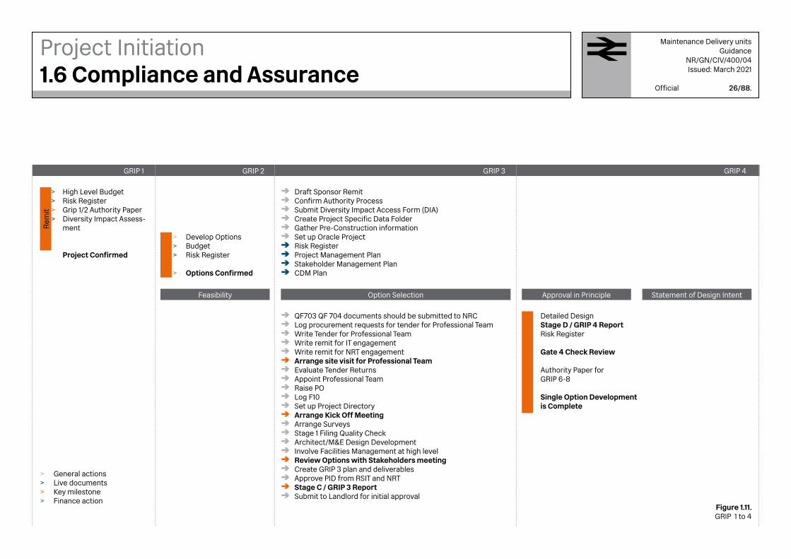
Figure 1.11.GRIP 1 to 4
Maintenance Delivery unitsGuidance
NR/GN/CIV/400/04Issued: March 2021
Official 26/88.
GRIP 1
Option Selection Approval in Principle Statement of Design IntentFeasibility
GRIP 2
Rem
it
GRIP 3 GRIP 4
Draft Sponsor Remit Confirm Authority Process Submit Diversity Impact Access Form (DIA)Create Project Specific Data Folder Gather Pre-Construction information Set up Oracle Project Risk Register Project Management Plan Stakeholder Management Plan CDM Plan
>>>>
QF703 QF 704 documents should be submitted to NRC Log procurement requests for tender for Professional Team Write Tender for Professional Team Write remit for IT engagement Write remit for NRT engagement Arrange site visit for Professional Team Evaluate Tender Returns Appoint Professional Team Raise PO Log F10 Set up Project Directory Arrange Kick Off Meeting Arrange Surveys Stage 1 Filing Quality Check Architect/M&E Design Development Involve Facilities Management at high level Review Options with Stakeholders meeting Create GRIP 3 plan and deliverables Approve PID from RSIT and NRT Stage C / GRIP 3 Report Submit to Landlord for initial approval
General actionsLive documentsKey milestoneFinance action
High Level Budget Risk Register Grip 1/2 Authority PaperDiversity Impact Assess-ment
Project Confirmed
Develop OptionsBudgetRisk Register
Options Confirmed
Detailed Design Stage D / GRIP 4 Report Risk Register
Gate 4 Check Review
Authority Paper for GRIP 6-8
Single Option Development is Complete
Project Initiation1.6 Compliance and Assurance
>>>>
>>>
>
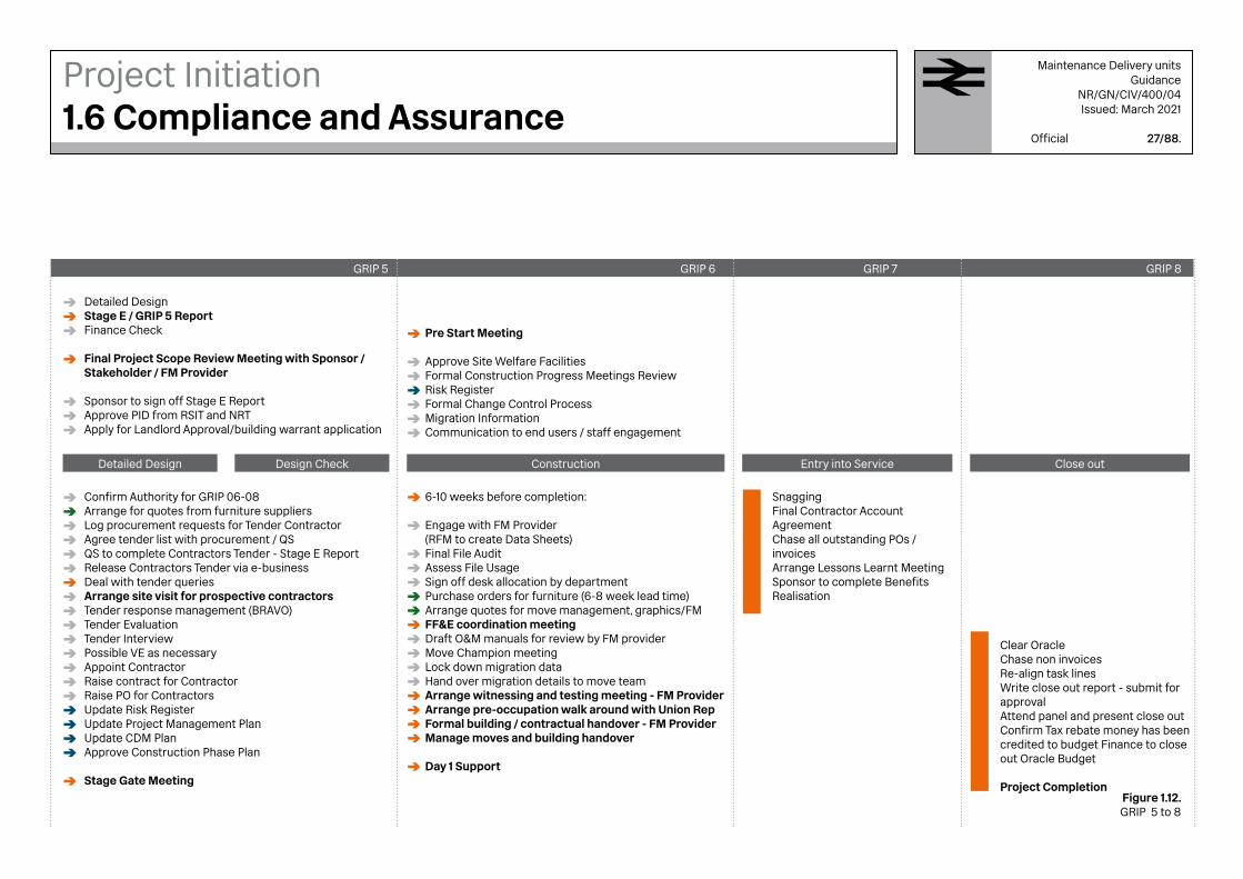
Figure 1.12.GRIP 5 to 8
Maintenance Delivery unitsGuidance
NR/GN/CIV/400/04Issued: March 2021
Official 27/88.
GRIP 5
Construction Entry into Service Close outDetailed Design Design Check
GRIP 6 GRIP 7 GRIP 8
Detailed Design Stage E / GRIP 5 Report Finance Check
Final Project Scope Review Meeting with Sponsor / Stakeholder / FM Provider
Sponsor to sign off Stage E Report Approve PID from RSIT and NRT Apply for Landlord Approval/building warrant application
Pre Start Meeting
Approve Site Welfare FacilitiesFormal Construction Progress Meetings Review Risk RegisterFormal Change Control ProcessMigration InformationCommunication to end users / staff engagement
6-10 weeks before completion:
Engage with FM Provider (RFM to create Data Sheets) Final File Audit Assess File Usage Sign off desk allocation by department Purchase orders for furniture (6-8 week lead time) Arrange quotes for move management, graphics/FMFF&E coordination meeting Draft O&M manuals for review by FM provider Move Champion meeting Lock down migration data Hand over migration details to move team Arrange witnessing and testing meeting - FM Provider Arrange pre-occupation walk around with Union Rep Formal building / contractual handover - FM Provider Manage moves and building handover
Day 1 Support
Confirm Authority for GRIP 06-08 Arrange for quotes from furniture suppliers Log procurement requests for Tender ContractorAgree tender list with procurement / QSQS to complete Contractors Tender - Stage E ReportRelease Contractors Tender via e-businessDeal with tender queriesArrange site visit for prospective contractorsTender response management (BRAVO)Tender EvaluationTender InterviewPossible VE as necessaryAppoint ContractorRaise contract for ContractorRaise PO for ContractorsUpdate Risk RegisterUpdate Project Management PlanUpdate CDM PlanApprove Construction Phase Plan
Stage Gate Meeting
Snagging Final Contractor Account Agreement Chase all outstanding POs / invoices Arrange Lessons Learnt MeetingSponsor to complete Benefits Realisation
Clear Oracle Chase non invoices Re-align task lines Write close out report - submit for approval Attend panel and present close out Confirm Tax rebate money has been credited to budget Finance to close out Oracle Budget
Project Completion
Project Initiation1.6 Compliance and Assurance
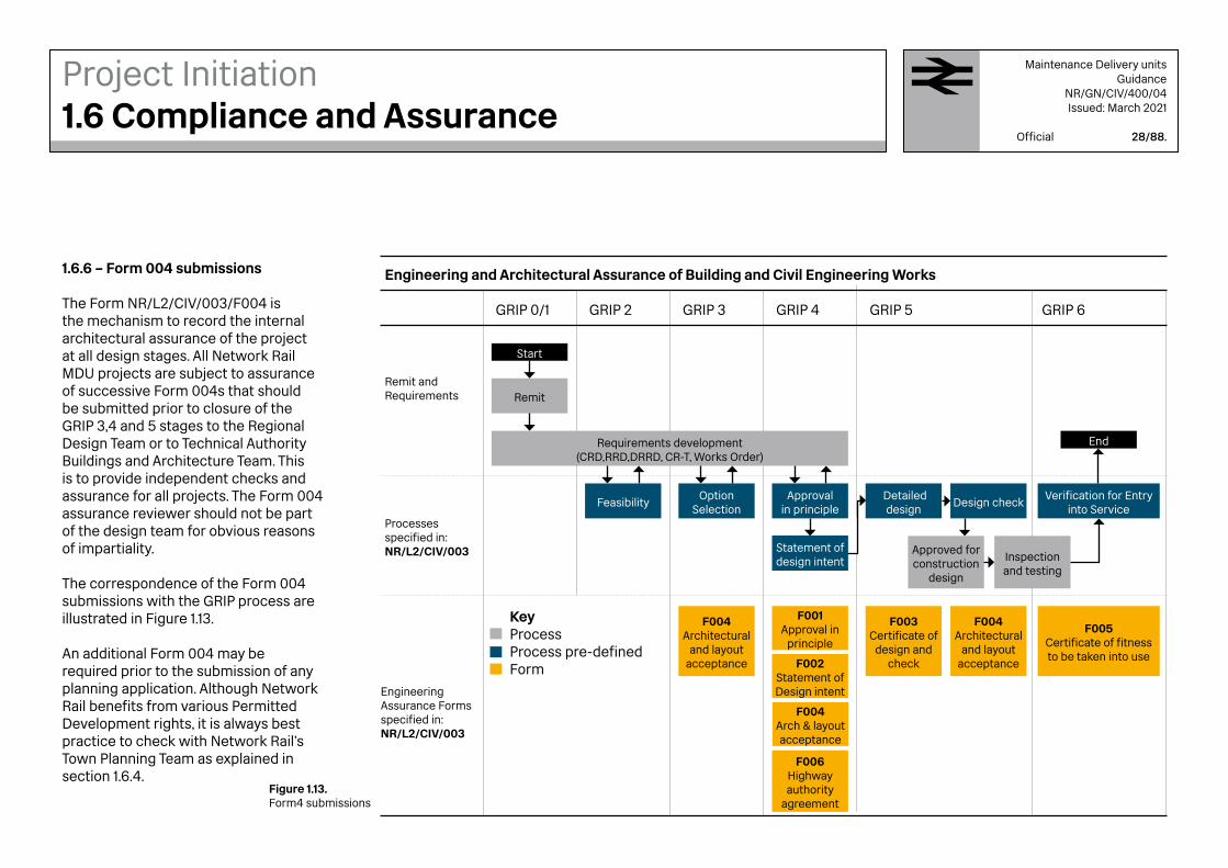
Figure 1.13.Form4 submissions
Maintenance Delivery unitsGuidance
NR/GN/CIV/400/04Issued: March 2021
Official 28/88.
1.6.6 – Form 004 submissions
The Form NR/L2/CIV/003/F004 is the mechanism to record the internal architectural assurance of the project at all design stages. All Network Rail MDU projects are subject to assurance of successive Form 004s that should be submitted prior to closure of the GRIP 3,4 and 5 stages to the Regional Design Team or to Technical Authority Buildings and Architecture Team. This is to provide independent checks and assurance for all projects. The Form 004 assurance reviewer should not be part of the design team for obvious reasons of impartiality.
The correspondence of the Form 004 submissions with the GRIP process are illustrated in Figure 1.13.
An additional Form 004 may be required prior to the submission of any planning application. Although Network Rail benefits from various Permitted Development rights, it is always best practice to check with Network Rail’s Town Planning Team as explained in section 1.6.4.
Project Initiation1.6 Compliance and Assurance
GRIP 0/1
Remit and Requirements
Processes specified in: NR/L2/CIV/003
Engineering Assurance Forms specified in: NR/L2/CIV/003
GRIP 2 GRIP 3 GRIP 4 GRIP 5 GRIP 6
Engineering and Architectural Assurance of Building and Civil Engineering Works
Start
End
Remit
Feasibility
F004Architectural
and layout acceptance
F004Architectural
and layout acceptance
F005Certificate of fitness to be taken into use
F003Certificate of
design and check
F001Approval in
principle
F002Statement ofDesign intent
F004Arch & layout acceptance
F006Highway authority
agreement
Option Selection
Approval in principle
Detaileddesign
Verification for Entry into Service
Statement ofdesign intent
Design check
Approved for construction
design
Inspection and testing
Requirements development(CRD,RRD,DRRD, CR-T, Works Order)
KeyProcessProcess pre-definedForm

1.6.7 – Construction Design Management (CDM)
CDM applies to all construction work undertaken by or on the behalf of Network Rail as a client and covers any asset owned, managed, or occupied by Network Rail.
All design should be considered under CDM both under constructibility and maintainability of the building in a safe manner. Designers should demonstrate compliance with CDM legislation from conception to completion of a project.
All tasks in Figure 1.14 should be captured at Corporate level, Business function level and Project level . All relevant standards listed should also be followed.
Project Initiation1.6 Compliance and Assurance
Figure 1.14.Construction Design Management
Maintenance Delivery unitsGuidance
NR/GN/CIV/400/04Issued: March 2021
Official 29/88.
Health and safety management system
CDM management
CDM plan
Task Briefing Sheet (TBS)
Task Standard or Legislation reference
Application of CDM
RACI charts
Construction Phase Plan (CPP)
GRIP deliverables
NR/L2/OHS/0047
Health and Safety file
Contract strategy mapping tool
Work Package Plan (WPP)
Contracts
NR/L2/INF/02202
Work Planning NR/L2/OHS/0044
Corporate level
Business function level
Project level
Project Initiation1.7 Constructibility Review
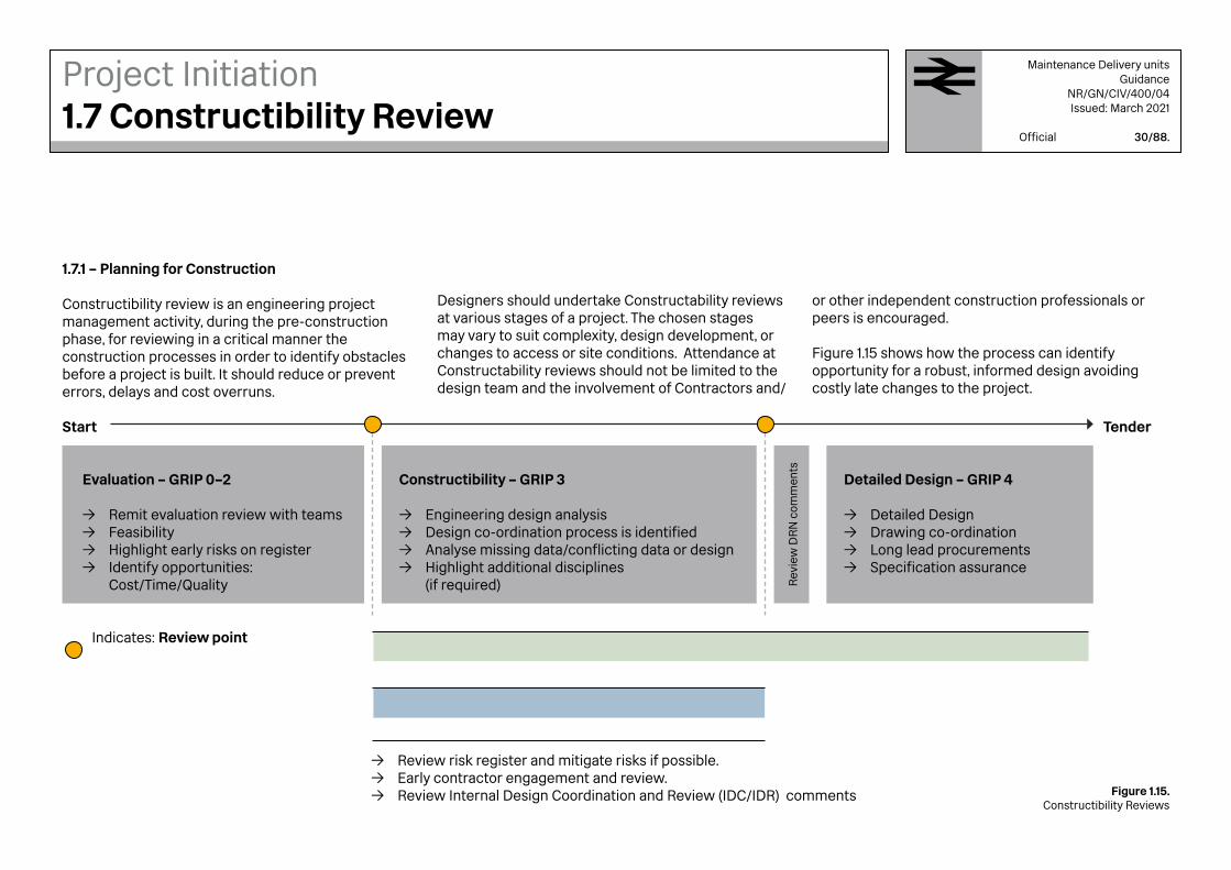
Figure 1.15.Constructibility Reviews
Maintenance Delivery unitsGuidance
NR/GN/CIV/400/04Issued: March 2021
Official 30/88.
Start
Indicates: Review point
Tender
Evaluation – GRIP 0–2
→ Remit evaluation review with teams → Feasibility → Highlight early risks on register → Identify opportunities:
Cost/Time/Quality Rev
iew
DR
N c
omm
ents
Constructibility – GRIP 3
→ Engineering design analysis → Design co-ordination process is identified → Analyse missing data/conflicting data or design → Highlight additional disciplines
(if required)
→ Review risk register and mitigate risks if possible. → Early contractor engagement and review. → Review Internal Design Coordination and Review (IDC/IDR) comments
Detailed Design – GRIP 4
→ Detailed Design → Drawing co-ordination → Long lead procurements → Specification assurance
1.7.1 – Planning for Construction
Constructibility review is an engineering project management activity, during the pre-construction phase, for reviewing in a critical manner the construction processes in order to identify obstacles before a project is built. It should reduce or prevent errors, delays and cost overruns.
Designers should undertake Constructability reviews at various stages of a project. The chosen stages may vary to suit complexity, design development, or changes to access or site conditions. Attendance at Constructability reviews should not be limited to the design team and the involvement of Contractors and/
or other independent construction professionals or peers is encouraged.
Figure 1.15 shows how the process can identify opportunity for a robust, informed design avoiding costly late changes to the project.

2Maintenance Delivery UnitSpace Planning

Image 2.1 Multifunctional area
Edinburgh

2.1.1 – Basic Space Requirements
All areas within an MDU should be well considered and efficient in use, avoiding wasted space. An MDU should not contain areas which are too small, unsafe and not fit for purpose.
Figure 2.1 explains key considerations when allocating space for the areas that could be meeting rooms, office areas or warehouse storage space. The process and issues to consider should be the same across any design.
In order to provide the required space a list of occupiers should be established and their roles clarified considering also the time of day and the frequency that they will be using the facilities. Allowance should also be allowed for any envisaged variations in the occupancy patterns.
Areas should provide enough space for walkways and circulation without interruption. Additional consideration should be made for persons with reduced mobility.
Furniture provision should form an integral part of allocating room dimensions and layout.(See section 2.5.1)
UsersThe amount of people who are required to use the
space should be defined within the remit.
Example
'8' person meeting room
FurnitureArea for fixed furniture and circulation space
around this furniture, based on the number of
people using the space.
Example '8' chairs, adequate table space, circulation space
around the furniture.
RegulationWhen designing a room or facility, all regulations
(stipulated in section 1.2 of this document)
should be adhered to. These are in place for safe
operation and design of all facilities.
Area
Users
Furniture
Regulation
Space Planning2.1 Area planning
Figure 2.1Planning Key Consideration
Maintenance Delivery unitsGuidance
NR/GN/CIV/400/04Issued: March 2021
Official 33/88.

Hard wearing zones which display robust material choice for maintenance staff.
Soft furnished zones, such as offices and meeting rooms should be comfortably furnished to create an inviting working environment.
Highlights the key zones within an MDU.
Collaboration zones; where conversations can happen.
2.1.2 – Interactions
Zone interaction should be facilitated within MDUs so that both office and maintenance staff have collaboration zones where they can meet and work together. These areas do not always have to be a formal meeting areas. As shown on the Figure 2.2 these interactions should form part of the design.
External stores
Workshops
Tea point
Meeting room
Breakoutzones
Waiting area
Lockers
Showers
Toilets
Storage
Meetingroom
Meetingroom
Print area (OSC)
Internalstores
Mess area Office
Reception
Space Planning2.1 Area planning
Figure 2.2Interaction between Zones
Maintenance Delivery unitsGuidance
NR/GN/CIV/400/04Issued: March 2021
Official 34/88.

2.2.1 – Work Routines
Although site operatives (to be distinguished from office staff) carry out different tasks there are still some common activities which take place in their daily routine and these are indicated in Figure 2.3 and below.
→ De-contaminate :
These areas should be hard-wearing, sufficiently heated and ventilated to avoid bad smells from any damp equipment or clothing.
→ Cleanse :
These areas should also be well heated and ventilated, hard-wearing and water-tight.
→ Refresh :
Staff entering this area should be free from dirt and oil, ready to change into clean clothes. Lockers should be allocated adequately, including a split for male and female spaces.
→ Recharge :
Time to recharge and refuel in a hard-wearing but comfortable environment. Interchangeable areas which can be used for eating and also large briefings.
Space Planning2.2 Site Operatives
Figure 2.3Site Operatives' Daily Pattern
Image 2.2A MDU Drying Room
Maintenance Delivery unitsGuidance
NR/GN/CIV/400/04Issued: March 2021
Official 35/88.
De-contaminate Cleanse Refresh Recharge
Laundry
Drying room
Showers
WC
Lockers
Clean clothes
Mess area
Food
Debrief
On site

2.3.1 – Internal and External Areas
A list of typical internal and external areas is provided in Figure2.4. More detailed information can be found in Section 3 of this document.
All spaces allocated within an MDU should be discussed and captured in the remit.
Rooms have been categorised as follows:
→ Mandatory These are expected to appear in most facilities, however they should still be confirmed by the client team within the Remit.
→ Optional These types of facilities could be team or location specific, in some cases evidence of the design decision for including these rooms should be presented within the Form 004.
A DIA should still be completed on all schemes and provide evidence as to why specific rooms might not be required.
Space Planning2.3 Areas Checklist
Figure 2.4Room Schedule
Maintenance Delivery unitsGuidance
NR/GN/CIV/400/04Issued: March 2021
Official 36/88.
Accessible: WC, showers, changingBreakout areasBriefing areasCleaners storageComms / Server / Plant room *Drying roomEquipment / material storageLaundry spaceLift *Main office areaMale / Female changing roomsMale / Female showersMale / Female WCMedical or First aid areaMeeting spaceMess areaOSC (Office Service Centre)Storage space or roomTea point or Kitchen
ArchiveCharging roomControl roomDrawing centre / layout spaceEquipment quarantine areaGym *Hot desk areaInterview roomLibrary *Post room *Quiet room *Reception / Entrance lobby *Specific team officesWarehouse *
Mandatory Optional
Cycle storageEntrance gateParkingPerimeter fencingSafe walking routesSmoking areaWaste area
Calibration areaCOSH storesExternal stores *Forklift area *Gas compoundHGV parking / turning zone •Skip storage *Van parking
General
Dependant on a DIA
Dependant on building size or function
* Indicates reasoning required

Figure 2.5Site Activity Zones
Maintenance Delivery unitsGuidance
NR/GN/CIV/400/04Issued: March 2021
Official 37/88.
2.4.1 – Circulation
Thought and care should be given to the operation and design of the external areas, that are just as important as internal spaces. Segregation, as illustrated in Figure 2.5, should be considered to provide safe operation throughout. Vehicle access, size, turning circles and weight are some of the many elements that should be considered during the design.
2.4.2 – Site entrance and compound
A compound should be secure, controlled with CCTV and surrounded my palisade fencing. Some sites could require a gate house for added security for the entrance. A site security strategy should be provided for safety and crime prevention.
2.4.2 – Safety
The layout should not endanger staff.Separation of areas should provide minimal clash points, example areas include; Staff car park, MDU parking, pick up zone and a separate route for MDU traffic to take before loading or unloading. A one-way route should be in place with safe walking routes highlighted for staff.
Secure site fencing
Site access gate
All vehicle circulation
MDU only vehicle circulation
Space Planning2.4 External Site Planning
Staff safeWalking route Staff car parkMDU
MDU vehicleParking
MDU traffic only
One-way system
ExternalStores
Pick up Zone
Warehouse
Reception &
Staff en-trance
Site access gate
Key areas
Office staff & visitor areas
Maintenance staff areas
Key safety zones
One
-way
sys
tem

2.5.1 – Anticipating Change
MDUs should be adaptable for the future. For example, a site could be used for a certain project over a three year period and then be required to adapt for different project or teams. To reduce overall cost, such factors should be considered throughout the initial design phase.
Even if no predictable changes are planned, the demographics and staffing levels of the MDU can be subject to natural change and it is sensible to allow some flexibility into the design. See section 1.2.8 for guidance on allowances for toilet and washing provisions and how they may need to be adapted for change.
.
Space Planning2.5 Future Adaptation
Figure 2.6Future Proofing
Versatile (space) → Open plan → Moveable walls / bi-folding partitions → Wide corridors → Frame Construction → Flexible ducts → Storage space → Extra capacity service points
Adjustable (task) → Plug and play elements (in breakout areas) → User control → Stackable, easy to store furniture → Non fixed objects (open plan) → Grouping of washing and changing facilities
Moveable (location) → Component weight → Kit of parts → Easy connections → Portable
Able to be refitted (performance) → Access points → Standard shapes → Dry connections → Co-ordinated components
Convertible (function) → Loose fit → Raised floors → Simplicity → Dropped ceilings → Multi-functional spaces
Scale (size) → Product platforms → Local materials → Known techniques → Modular units → Extra space → Structural repetition → Divisible/flexible rooms
AdaptableThe capacity for a building to accommodate effectively to the evolving demands of its context, maximising its value
Maintenance Delivery unitsGuidance
NR/GN/CIV/400/04Issued: March 2021
Official 38/88.
Adaptable

3Maintenance Delivery UnitsDesign and Fit Out

Image 3.1New facility during construction
Middlesbrough MDU
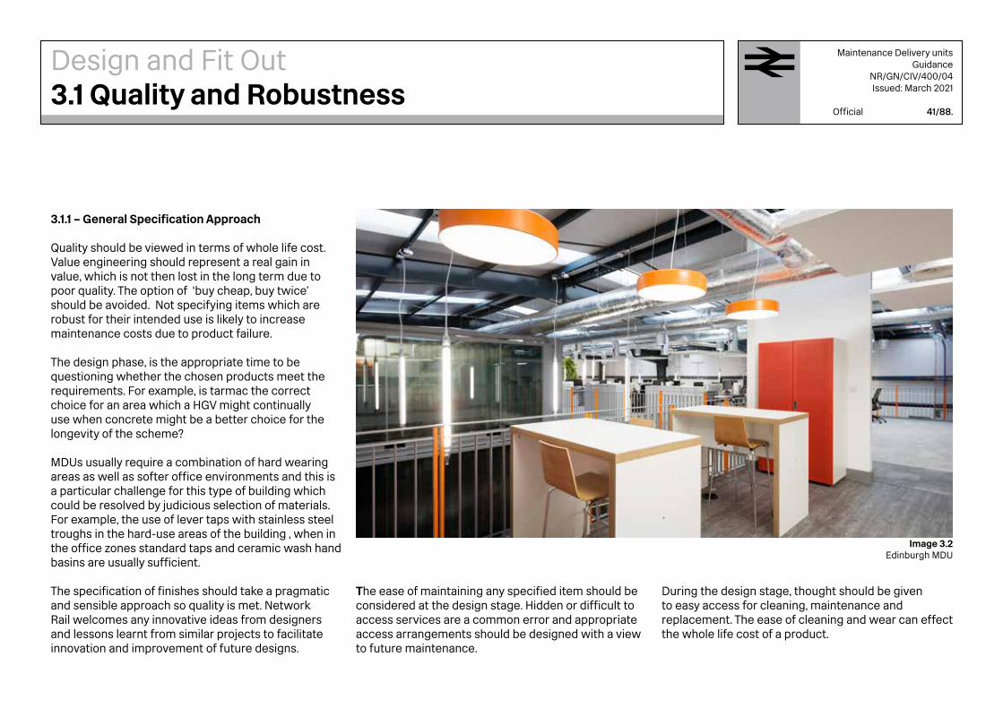
3.1.1 – General Specification Approach
Quality should be viewed in terms of whole life cost. Value engineering should represent a real gain in value, which is not then lost in the long term due to poor quality. The option of ‘buy cheap, buy twice’ should be avoided. Not specifying items which are robust for their intended use is likely to increase maintenance costs due to product failure.
The design phase, is the appropriate time to be questioning whether the chosen products meet the requirements. For example, is tarmac the correct choice for an area which a HGV might continually use when concrete might be a better choice for the longevity of the scheme?
MDUs usually require a combination of hard wearing areas as well as softer office environments and this is a particular challenge for this type of building which could be resolved by judicious selection of materials.For example, the use of lever taps with stainless steel troughs in the hard-use areas of the building , when in the office zones standard taps and ceramic wash hand basins are usually sufficient. The specification of finishes should take a pragmatic and sensible approach so quality is met. Network Rail welcomes any innovative ideas from designers and lessons learnt from similar projects to facilitate innovation and improvement of future designs.
Design and Fit Out3.1 Quality and Robustness
The ease of maintaining any specified item should be considered at the design stage. Hidden or difficult to access services are a common error and appropriate access arrangements should be designed with a view to future maintenance.
During the design stage, thought should be given to easy access for cleaning, maintenance and replacement. The ease of cleaning and wear can effect the whole life cost of a product.
Maintenance Delivery unitsGuidance
NR/GN/CIV/400/04Issued: March 2021
Official 41/88.
Image 3.2Edinburgh MDU

3.2.1 – Internal Areas
All internal spaces should be well considered and be big enough to facilitate the number of users, space for furniture and circulation (including space for PRM).Sections 3.2.2 to 3.2.25 cover the typical areas listed in Section 2.3. Typical sizes are provided where possible but these should not be taken at face value and should be verified for the remit and also during initial design stages.
3.2.2 – Entrance /Reception area :
→ Typically not less that 24sqm. → Preferably sliding doors should be provided. External canopy and entrance matt
are required. → Access to WC including Accessible WC should be close by. → Signing in and monitoring systems. → Key way-finding information. → Proximity to vertical circulation if relevant. → Break out waiting area (Generally under visibility of reception staff and a
controlled waiting zone for security requirements.). → Meeting rooms (Front of house) - For visitors meeting with Network Rail staff
containing IT support (consultation with Network Rail Information Technology (NRIT) is required to understand the requirements of the room).
→ A separate staff entrance that is close to changing areas may be required.
3.2.3 – Break out areas:
→ Booths can be used for small ad-hoc meetings between staff. There are furniture options available that can facilitate this task.
→ Typically 9sqm per 15 desks.
Design and Fit Out3.2 Internal Provisions
3.2.4 – Hot desk area :
→ Seated area within the mess with standalone PC and screens. → Typically 5sqm per person.
Maintenance Delivery unitsGuidance
NR/GN/CIV/400/04Issued: March 2021
Official 42/88.
Image 3.4Breakout Area
Image 3.3Reception

3.2.5 – Mess area :
→ Understanding the rotas and frequency of use are required to establish a sensible size that is sufficient, based on shift patterns / holidays and not oversized.
→ Mess seating is typically moveable hard-wearing furniture for ease of cleaning and maintenance. Sufficient space should be allowed within the remit.
→ This area is usually the largest space and can often be used for safety briefs. See item 3.2.6.
3.2.6 – Briefing area :
→ Wall space should be allowed for appropriate technology to perform the task of briefing. This space should have wall boards or write on walls and usually require screens and laptop connectivity for staff briefings.
3.2.7 – Tea point or kitchen :
→ Requires an instant hot/cold water tap and commercial grade fridge for staff who bring food to the MDU please see Appendix E for generic drawings.
→ Some operational sites could require a full kitchen due to shift patterns or location of the site. These requirements should be captured within the remit and determined by the DIA.
3.2.8 – WCs :
→ See section 1.2.8 for advice on extent of provisions. Male and female facilities should be separated but adjacent to facilitate modification in case of demographic changes.
→ Number and location of Accessible Facilities should conform to Building Regulations Part M and is subject to the outcome of DIA and staff consultation.
Image 3.5 Mess Area
Image 3.6Tea Point
Design and Fit Out3.2 Internal Provisions
Maintenance Delivery unitsGuidance
NR/GN/CIV/400/04Issued: March 2021
Official 43/88.

3.2.9 – Control / planning area :
→ Rooms dedicated to project planning that typically contain layout space and white boards where information is manually written and displayed.
→ Storage of site drawing information and storage chests might also be required. → These facilities may also require specialist equipment that requires advice from
NRIT specialists for the design integration.
3.2.10 – Charging equipment rooms :
→ Rooms dedicated for the charging of site equipment. Typically they have plenty of shelving and charge points. Rooms should also be lockable and monitored.
→ Could be combined with storage of surveying equipment.
3.2.11 – First aid Room :
→ A medical room should contain a treatment bed, surgical trolley, stainless steel bin, double wall cabinet, two chairs and a sink.
3.2.12 – Cleaners store :
→ The cleaners cupboard should have a cleaners sink with grating and shelving for cleaning products.
3.2.13 – Reflection room :
→ Quiet spaces should be allocated for staff to meditate, pray or relax. These areas should be neutral and welcoming for all. They should be well ventilated, sensitively lit and calm.
→ See Appendix E - Reflection room drawing for further information.
Design and Fit Out3.2 Internal Provisions
3.2.14 – Archive room :
→ A general storage room for archived projects and information may be required. Consultation with the end user should determine the type and amount of storage required.
Maintenance Delivery unitsGuidance
NR/GN/CIV/400/04Issued: March 2021
Official 44/88.
Image 3.7Control and planning area

3.2.15 – Drying rooms :
→ Allow typically 0.5sqm per font line staff member. Cage dimensions are typically 450x225mm.
→ The room should incorporate mesh style lockers and access to the laundry space for depositing of dirty PPE.
→ The ventilation and heating should be suitable for the purpose of drying wet PPE equipment.
3.2.16 – Showers :
→ See section 1.2.8 for advice on extent of provisions. Allow typically 4.5sqm per shower. Male and female facilities should be separated but adjacent to facilitate modification in case of demographic changes.
→ Isolated unisex showers for one person at a time require a door lockable from the inside.
→ Showers should be well ventilated and well drained,
3.2.17 – Changing rooms :
→ A locker for every member of staff incorporating benching is normally required. → Allow typically 0.7sqm per member of staff. Lockers are typically 500x500mm.
3.2.18 – Laundry room :
→ A storage space that allows for 200litre laundry roller trolleys. → The location of the laundry space should allow for easy access to collect and
deliver laundry by the service company.
Note : The drying room, laundry, showers WC and locker room should work together as a system to facilitate a flow for staff going out or returning from external sites.
Design and Fit Out3.2 Internal Provisions
3.2.19 – Staff personal lockers :
→ Every member of staff should have a locker (other than changing) for personal items, using combination lock.
Maintenance Delivery unitsGuidance
NR/GN/CIV/400/04Issued: March 2021
Official 45/88.
Image 3.8Drying Room
Image 3.9Changing Room

3.2.20 – Main Office Areas :
→ The office areas should be open plan to facilitate work, interaction and movement.
→ Typically allow 6sqm per desk, that should be well lit and serviced with IT. → A 1.5m planning grid is recommended as it is compatible with building
components of 300 and 500mm. → The office area should be associated with sufficient Meeting Spaces and
Service Centres.
3.2.21 – Meeting Spaces :
→ Depending on location, a range of meeting rooms varying in size: 4 person(9sqm), 12 person(27sqm), or 18 person (40sqm) may be required.
→ Typically all rooms would require audiovisual screens. → 4 person meeting areas could be allocated in the form of breakout booths. → For large meetings, the mess area could double up as a briefing space.
3.2.22 – Office Service Centre (OSC) :
→ Space for stationary, printers, waste management, storage cupboards and layout space should be provided.
3.2.23 – Cleaners' Storage :
→ Typically one room per floor level 3 to 5sqm, → Each room should have a cleaner’s sink, an integral S-steel bucket stand and
racking for storage of cleaning equipment. → Allow for 900mm x 900mm activity space and minimum of 1200mm circulation
space for a trolley.
Design and Fit Out3.2 Internal Provisions
Image 3.10 Office Service Centre
3.2.24 – Gym :
→ For Health and Safety reasons the cost of staffing gyms is normally too onerous for Network Rail to justify the running expense. However, in cases where it is considered, it should be located at ground level due to the weight of the equipment.
Maintenance Delivery unitsGuidance
NR/GN/CIV/400/04Issued: March 2021
Official 46/88.
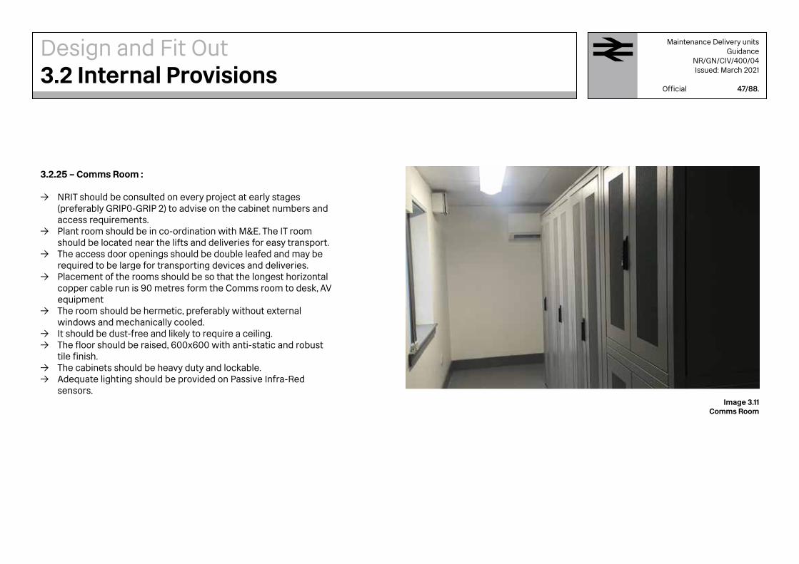
3.2.25 – Comms Room :
→ NRIT should be consulted on every project at early stages (preferably GRIP0-GRIP 2) to advise on the cabinet numbers and access requirements.
→ Plant room should be in co-ordination with M&E. The IT room should be located near the lifts and deliveries for easy transport.
→ The access door openings should be double leafed and may be required to be large for transporting devices and deliveries.
→ Placement of the rooms should be so that the longest horizontal copper cable run is 90 metres form the Comms room to desk, AV equipment
→ The room should be hermetic, preferably without external windows and mechanically cooled.
→ It should be dust-free and likely to require a ceiling. → The floor should be raised, 600x600 with anti-static and robust
tile finish. → The cabinets should be heavy duty and lockable. → Adequate lighting should be provided on Passive Infra-Red
sensors.
Design and Fit Out3.2 Internal Provisions
Image 3.11 Comms Room
Maintenance Delivery unitsGuidance
NR/GN/CIV/400/04Issued: March 2021
Official 47/88.

SEMI PRIVATE AREA
These areas are subject to less wear and tear. Higher comfort should be the design objective, focusing on environmental control (acoustic, temperature, ambiance).
Examples include : Office areas, interview rooms, and meeting rooms.
INTERMEDIATE AREA
Intermediate areas are spaces which are more public and require more durable materials that get cleaned more often but also maintain a high level of comfort for the users.
Examples include : Mess rooms, kitchenette, break out areas, receptions.
HIGH INTENSITY AREA
These high traffic areas should be designed with an emphasis on durability and longevity of the materials.
Examples include : Locker rooms, drying rooms, WCs, showers, entrances, corridors, stairwells.
3.3.1 – Internal finishes
Different finishes specifications are required based on the intensity of use,and type of users. Three examples are given below of how finishes could differ for typical areas
Design and Fit Out3.3 Look and Feel
Image 3.12 Office Area Image 3.13 Mess Area Image 3.14 Vertical Circulation
Maintenance Delivery unitsGuidance
NR/GN/CIV/400/04Issued: March 2021
Official 48/88.

3.3.2 –Colour Palette
The use of colour and graphics is encouraged to enliven workplaces and highlight or distinguish different areas of the office environment for variety and also for orientation.
The use of specific colours across the Network Rail workplace estate can help to establish a common look and feel. This comes with careful planning of spaces and specification of features and facilities alongside the creative use of colour and lighting.
Designers are asked to apply the Corporate Workplace Management DNA colour palette shown in section 3.3.3 as the basis for their colour schemes with a view of designing work environments with character.
Design and Fit Out3.3 Look and Feel
Image 3.16 Colour Palette in York
Image 3.15 Colour Palette in Edinburgh
Image 3.17 Colour Palette in Birmingham
Maintenance Delivery unitsGuidance
NR/GN/CIV/400/04Issued: March 2021
Official 49/88.

Design and Fit Out3.3 Look and Feel
Figure 3.1The NR Workplace Colour Palette
Maintenance Delivery unitsGuidance
NR/GN/CIV/400/04Issued: March 2021
Official 50/88.
3.3.3 - How to use the Colour Palette
This colour matrix shown in Figure 3.1 aims to provide a choice of 5 consistent ambiances to the look and feel of the workplaces. Other colours could be added as long as they are complimentary to this colour scheme. This colour range is based upon the Dulux Trade system. Paint used can be Dulux or similar approved, providing that the colours are compatibly matched.
The combinations are assorted vertically into 5 pre-set colour palettes. However, the colours are not limited to the vertical palettes, for example a scheme could consist of colours 1.1, 2.2, 5.1 and 5.4 – This would be acceptable as they are all still from the same range. This is to allow some flexibility within the design parameters, as long as they are appropriate for the intended purpose.
Any proposed colour scheme should be agreed with the architectural reviewer of the Form 004.
Note: Colours could appear different on screen, please use the Dulux colour code (*) when specifying.
1.1 90RR 35/606*
2.1 20YY 77/128*
3.110YY 74/063*
4.182YY 85/038*
5.130YY 78/035*
1.230YY 33/613*
2.2 40YY 77/242*
3.270RR 38/246*
4.270YY 63/326*
5.250BG 62/133*
1.3 10YY 09/200*
2.347RR 32/383*
3.370YR 31/135*
4.380YY 71/380*
5.390GG 40/115*
1.4 10YY 24/476*
2.480YR 28/650*
3.475RR 06/129*
4.470YY 37/366*
5.4 90GG 11/131*
1.5 10RB 08/125*
2.500NN 20/000*
3.550RB 13/107*
4.570YY 18/350*
5.5 70BG 07/086*

3.3.4 –Signs
MDUs should have sufficiently clear direction signs for the safe operation of the site. National and Route consistency across the MDUs should be aimed for. Specifications and fixings should be fit for purpose and all signs should be installed by a competent sign contractor.
Large scale graphics can be applied internally and could be used as a key element to enhance the Interior Design as shown in Image 3.19. Clear and easily understood graphics should be used throughout for communication and orientation.
Please note that some signs on a site my have to comply with specific Rail or Highway standards. An example of this could be track access gates onto the live Railway or site entry points where staff and MDU vehicles join the public highway.
Signs should be considered as a key design element and should not be picked up at a late design stage or after the site is operational.
Fire safety signs and refuge points , in line with the fire strategy for the building, should be included.
An electrical engineer should be consulted to verify that sufficient power is available for illuminated fire exit signs and any other sign related lighting.
Design and Fit Out3.3 Look and Feel
Image 3.18 Orientation Sign printed onto wall
Image 3.19Large Scale Graphics film applied onto glass
Maintenance Delivery unitsGuidance
NR/GN/CIV/400/04Issued: March 2021
Official 51/88.

3.3.5 – Furniture
MDU furniture should be robust and fit for purpose. The furniture specification should be based on the teams and types of activities that take place within the area.
Hard wearing furniture should be used in public areas where it is likely to become dirty more quickly. Within mess areas for example, hard plastic (or similar) chairs offer an easy to clean surface.
Design and Fit Out3.3 Look and Feel
Soft furnishings should be used in areas subject to less intensive use and are more private . Soft furnishings should be avoided in food areas to prevent stains and spillages.
Image 3.20Hard Wearing Furniture
Image 3.21Soft Furnishing
Maintenance Delivery unitsGuidance
NR/GN/CIV/400/04Issued: March 2021
Official 52/88.

3.3.6 - Technology Integration:
The technology required for the final building should be driven by the number and role of users within the organisation. Is it therefore vital that these requirements are understood early in the design process.
Design teams should include representatives from Route Services IT (RSIT) and Network Rail Telecoms (NRT) to advise on all aspects for telephony, wired data connectivity, Wi-Fi, printing and technology for meeting rooms and break out spaces that should be incorporated into the MDU.
Consideration should also be given at early stages of the design to the services distribution and containment which are often added without proper integration of the overall structural and architectural design.
3.3.7 – Ceilings
Network Rail has a preference towards an exposed ceiling system where it is deemed practicable, There are nevertheless situations where suspended ceilings are more appropriate. The final strategy could be and should not exclude a mixed solution.
It should be noted that natural lighting via skylights is a healthy option for the well-being of the staff, and could also be used to reduce the building overheads.
Design and Fit Out3.3 Look and Feel
The following points highlight both advantages and disadvantages of exposed soffits versus suspended ceilings, to assist the designer in making the correct choice,.
Exposed Soffits advantages are: → Extra Space – An exposed soffit maximises the
size of the room giving a feeling of space. It is worth noting, some teams across the business could benefit from the extra height to display screens with information.
→ Maintenance – Exposed services allow for ease of maintenance and future adaptations. Services are more organised and easy to find.
→ Cooling -It allows hot air to rise and dissipate assisting the climate control system.
→ Cost and Time saving– cost of materials, labour and time required to fit a lowered ceiling.
→ Design Potential – allows more freedom with the lighting. Service distribution is visible and can be decorative.
Exposed Soffits disadvantages are: → Energy Consumption – Open ceilings provide
a greater volume of space to heat and might increase energy consumption.
→ Acoustic control – This could pose an issue in open plan office but can be overcome by use of acoustic baffles and sound absorbing materials.
→ Humidity - In wet areas, it is not practical to expose the services and a ceiling is required.
Suspended Ceilings advantages are: → Concealed Services– Less attention required in
routing and visual appearance of service routes. → Thermal performance – The ceiling can provide an
extra thermal barrier.Suspended Ceilings disadvantages are:
→ Deterioration – Suspended ceiling tiles discolour and degrade over time.
→ Hidden Services- Difficult access to services will further degrade and misplace ceiling tiles.
Image 3.22Partly Exposed Soffit with easily accessible services
Maintenance Delivery unitsGuidance
NR/GN/CIV/400/04Issued: March 2021
Official 53/88.

3.4.1 – Storage Areas :
The following list is a guide only and the designer should understand the users and team requirements which may include the following storage facilities:
→ Signalling Storage → Welding & Grinding Storage → Telecoms Storage → Emergency and Temporary Speed Restrictions Group storage → Plant Tools Telecoms → Off-track Storage → Works Delivery Storage → Forklift Charging Zone → Point Heating Elements Storage (can be very long boxes) → Hazardous Substances Store (Subject to Risk Assessment and Storage/Control
Methodology)
Safe walking routes should be identified inside warehouses (as well as externally) where large vehicles are likely to be moving.
Please note : Prior to going to site pallets are likely to be wrapped ready with all the equipment for completing a task. A holding area should be provided for this purpose.
3.4.2 – Workshops for individual teams :
Individual teams are should be consulted directly for the correct requirements.
3.4.3 – Eye Wash Zone :
Generally located in the workshop areas , it should be provided with first-aid kits, eye washing unit (usually a trough sink with leaver taps) and a mirror.
Design and Fit Out3.4 Warehouse Provisions
3.4.4 – Cable racking store :
Due to the variation of sizes associated with the cabling for the different teams, consultation should be undertaken to establish the exact requirements of the racking. Racking can be both internal and/or external. Security should be considered as cable theft is common on the railway environment.
3.4.5 – Rail testing area :
An area set aside for testing track layout and equipment prior to installation on sites. This space could also be used for training.
3.4.6 – Calibration room :
A space allocated for the calibration of equipment used on site. Each MDU may have slightly different requirements in terms of equipment used.
Maintenance Delivery unitsGuidance
NR/GN/CIV/400/04Issued: March 2021
Official 54/88.
Image 3.23Equipment Collection Point

Maintenance Delivery unitsGuidance
NR/GN/CIV/400/04Issued: March 2021
Official 55/88.
3.5.1 – Lighting
Lighting is a very effective means to express the desired character of a space. A lighting design should be integrated with the proposals at an early stage. Lighting enhances the perception of space and reinforces the activity within the space. Lighting by natural light (with blinds to reduce sun glare if necessary) should be utilised as much as possible. Roof-lights are also very effective.
All internal and external lighting systems should facilitate efficient performance of visual tasks and meet the following design parameters:
→ CIBSE (Chartered Institution of Building Services Engineers) Code for Interior Lighting
→ CIBSE LG7 → Network Rail guide for office type building → Building Control Sections L and M → 17th Edition I.E.E. Regulations BS 7671 → BS 5266 Emergency Lighting
Lighting installations should also meet the following :
→ Light fittings should be grouped and controlled to take advantage of natural light. Automatic controls with movement sensors should be used to minimise energy consumption.
→ The lighting should be energy efficient and cost-effective to maintain.
Recommended Luminance Levels (lux) are as follows:
→ Entrance & Reception 200 → Corridors 200 → Open Plan Offices 400 - 450 → Small Offices 350 - 400 → Welfare & Mess Rooms 300 → Changing Rooms 300 → Toilets & Showers 200 → Comms Server Rooms 400 → Plant & Switch Rooms 300 → External Covered Stores 100 - 150 → External Walkways 30 - 50
3.5.2 – Emergency lighting
The emergency lighting installation should be coordinated with the general lighting system.
→ Level of emergency escape illumination should comply with BS 5266 and NR/L2/ELP/27238.
→ Luminance levels should be a minimum 5 lux in rooms and 3 lux in workshops generally. However subject to Risk Assessment some workshop areas may need full luminance levels.
→ 3-Hour battery powered maintenance-free illumination should be specified along escape routes and above emergency exit doors.
→ Emergency fittings should have test switching containment and cabling in all areas. The testing of the emergency lights should be operated from a 20 amp key switch located within sight of the fitting, either as part of the lighting switch assembly or directly adjacent it.
→ The Office, Toilets, Welfare, Corridors and Stairs areas should have recessed fittings. The remaining areas can have surface fittings.
It is advisable to conduct an emergency lighting risk assessment at an early design stage to facilitate the approval of the proposals by the NR Fire Specialist.
Design and Fit Out3.5 Lighting
Image 3.24Controlling ambiance with lighting

Maintenance Delivery unitsGuidance
NR/GN/CIV/400/04Issued: March 2021
Official 56/88.
3.6.1 - Small MDU buildings
Electric heating should be provided with thermostatic controls, designed to provide the space temperatures indicated under design parameters 3.6.5.
3.6.2 - Medium MDU buildings
Reverse cycle heat pumps should be specified where an all-electric installation is more effective than an Low Temperature Hot Water heating system, due to the large number of rooms requiring comfort cooling or where installing a gas supply would not be practical.
3.6.3 - Large MDU buildings
Heating system should be supplied from low temperature hot water boilers and supported where practically possible with low carbon offset initiatives.
3.6.6 - Boilers
High efficiency condensing gas fired boilers rated to suit the design heating load for winter conditions are usually preferred.
3.6.7 - Flues Flues should comply with Gas Safe requirements
3.6.8 - Circuit Pumps: All pumps should be in line twin head direct drive run/standby complete with anti-vibration mounts.
3.6.9 -Pressurisation Units Cabinet type units with remote vessel are preferred.
3.6.10 - Pipe-work
All inter connecting pipe-work should be complete with all isolating/regulating valves, strainers, gauges and test points.
All pipe-work and valves should be fully insulated, colour coded and hydraulically tested before delivery.
Design and Fit Out3.6 Heating
3.6.4 - Low temperature hot water heating (LTHW)
A gas heating system should be designed so that the designated areas of the building are maintained at the required temperature and constant temperature heating water is provided to air handling unit heater batteries.
Heating and cooling controls systems should be designed to avoid simultaneous operation in heating and cooling modes.
3.6.5 - Design Parameters
The heating of MDUs should be designed to the following parameters:
→ CIBSE Guide B → UK Building Regulations Part L2 → Low Temperature Hot Water Flow 82°C → Low Temperature Hot Water Return 71°C

Maintenance Delivery unitsGuidance
NR/GN/CIV/400/04Issued: March 2021
Official 57/88.
3.7.1 - General Requirements
The potential for natural ventilation of the building should be maximised by providing windows that can open. A designed natural ventilation system should be considered with all new buildings.
A minimum outdoor air supply of 10 litres person per second should be provided. The specific fan powerof the ventilation system should not exceed 2 W / litre/ second for general office installations.
The air handling unit should have intake and exhaust plenum’s, connected to external, weather protected louvres that also suit the architectural specifications. The system should be provided with supply and extract fans, plate heat exchanger, panel filters, bag filter, heating and frost coil and duct mounted silencers. The air handling units should be of the constant volume type providing full fresh air, tempered to 20°C. The distributed fresh air ductwork should be thermally insulated.
If the MDU is likely to be unoccupied for long periods of the day, it is preferable to have an overhead distribution. However if the building is expected to have a regular full occupancy, distribution under a raised floor with floor extracts is a viable alternative.
The office supply and extract ventilation system should distribute through the building via ductwork that is evenly distributed. It has been noted that in
a number of office environments delivered recently the ventilation outlets are not sufficiently distributed resulting in discomfort for the occupants who are either not close enough to an extract or too close to an extract that is blowing air too strongly.
3.9.2 - Design Parameters
The following design parameters are recommended: → CIBSE Guide A: Environmental design → CIBSE Guide B: Heating, ventilating,
air-conditioning and refrigeration. → Noise criteria to meet the requirements of the
room or area as previously stipulated. → CIBSE Guide F: Energy efficiency in buildings → Refrigerant R407c (or similar approved)
Internal Temperature to offices should be → Summer = 24oC ± 1oC → Winter = 21oC ± 1oC
Internal Temperature to Comms rooms should be → Summer = 24oC ± 1oC
→ Winter = 24oC ± 1oC
3.9.3 – Toilet Ventilation
WC supply and extract systems should comply with the same parameters as the general ventilation system, however the toilet system should be the full extract type for small toilets or have an overall negative pressure effect if an air-handling is required.
Design and Fit Out3.7 Ventilation
3.9.4 – Drying room Ventilation and Heating
An extract ventilation system should comply with the same parameters as the general ventilation system requirements. The system should have a speed control to allow settings between zero and full speed.
However the drying room system should be of the full extract type with the capacity to give 6 air changes per hour. It should have thermostatic electric heaters that are capable of maintaining the low level temperature at 20 ºC. The extract system should induce warm air movement upwards through the clothing racks. Under-floor or low level heating should be provided to allow a flow of rising air to dry clothes. For small MDUs individual air drying lockers are recommended.
3.6.8 – Air conditioning Engineering services
All cooling systems should be specified as inverter-driven VRF type with R410A refrigerant. Heating and cooling controls systems should be designed to avoid simultaneous operation in heating and cooling modes. Rooms where cooling should be provided are:
→ All meeting and interview rooms → Main administration offices → Open-plan offices → Comms/Server room

Maintenance Delivery unitsGuidance
NR/GN/CIV/400/04Issued: March 2021
Official 58/88.
3.8.1 – External Planning
MDUs are typically surrounded by open car parks,storage facilities, waste areas and workshop buildings (see section 3.4 for warehouse provisions). Wherever possible the position and orientation of buildings should have a clearly perceptible layout to facilitate entry and exit for staff, visitors and goods.
External car park and circulation areas include both operational and visitor zones. All walking routes should be segregated, clearly marked and adequately lit for visibility. Appropriate landscaping and drainage should also be considered throughout. Foul drainage may be required for vehicle and equipment washing. In other areas, permeable drainage should be considered to minimise the environmental impact. 3.8.2 – External stores :
The remit should capture the equipment storage requirements and this information should be used to determine the size of the external stores. Their location should be well considered so that it does not adversely affect the safety of the site. Adequate space for the pick up and drop off vehicles visiting these areas should be considered. All stores should have, where possible, well lit overhangs so that vans can load and unload in all conditions.
Design and Fit Out3.8 External Areas
3.8.3 – Parking :General car parking spaces should be allocated for staff and MDU vehicles, with potentially ever increasing requirements for vehicle charging points. Accessible parking should be located as near as possible to the building entrance and be compliant with the Equality Act 2010. MDU vehicles such as vans and Heavy Goods Vehicles require larger spaces and turning circles. Typical vehicle requirements and numbers should be provided by the client. Provision for cycles and motorcycles should also be included.
3.8.4 – Smoking AreasOut-door shelters should be provided where site staff and visitors can smoke comfortably and safely.
3.8.5 – Waste areasRefuse storage and compactor areas should be located strategically in a way that facilitates safe waste collection and also minimises distances for staff disposing the rubbish.
Image 3.25Approach to Mercier House, Derby
Image 3.26View from Mercier House, Derby

HEAVY DUTY AREAS
Areas related to intense work, utilising large loading equipment or storage of site equipment, including the road surfaces related to these areas.
Examples include : External storage, loading, HGV areas.
INTERMEDIATE AREAS
These areas encompass all pedestrian and semi permeable spaces in which all staff can access. They can also be utilised for the inclusion of a Sustainable Drainage System to deal with site rain water run off.
Examples include : Safe walking routes, site landscaping, car parking and cycle storage areas.
SOFT SURFACE AREAS
Natural landscaping shouldn’t be viewed as a ‘nice to have’ as sites can benefit greatly from the drainage and improved permeability, not to mention the health and well-being of the staff.
Examples include : Soakaways, natural landscaping, grass verges and pedestrian walkways.
3.8.6 – External finishes
Similar to Internal finishes, all external finishes are determined by the activities and types of traffic which frequent the area. All materials should be fit for purpose and can be categorised as follows :
Design and Fit Out3.8 External Areas
Maintenance Delivery unitsGuidance
NR/GN/CIV/400/04Issued: March 2021
Official 59/88.
Image 3.27 Image 3.28 Image 3.29

3.8.7 – Security
MDU sites should be controlled, safe and secure. Requirements should be risk assessed on a site by site basis and captured within the remit. A security strategy should be in place for all proposed schemes. The strategy should be agreed with the relevant Project Engineer and client team.
The building should be secure and monitored internallyin common spaces. The external site should be controlled via a CCTV system.
Space for all recording equipment should be allocated within the LAN/Comms room (see section 3.2.24). 3.8.8– Perimeter fence
The perimeter should be fully enclosed with suitable fencing. Certain sites may have access gates direct to the rail tracks.
3.8.9 –Access control
Vehicle and pedestrian gates should be provided where necessary, either sliding or swing gates with relevant access controls, as required within the clients remit.
The MDU should be secured by an automatic access control system. This should be fob activated access and include a video intercom on the main entrance door and all access gates. Visibility from the site office to the entrance gates is preferred along with remote gate control security cameras.
An intercom receiver should be installed within the main office space and an additional location should be agreed for every site.
Image 3.30External signs on walking route
Maintenance Delivery unitsGuidance
NR/GN/CIV/400/04Issued: March 2021
Official 60/88.
Design and Fit Out3.8 External Areas

4Maintenance Delivery UnitsAppendices

Image 4.1Internal Warehouse area
Edinburgh

Maintenance Delivery unitsGuidance
NR/GN/CIV/400/04Issued: March 2021
Official 63/88.
Below are lists of the most relevant standards and guidance documents referenced. These documents are drawn from a range of sources.
British/European/Other Standards:
→ Building Regulations → CIBSE Guides and Publications → BS EN 81 – Construction and Installation of
Passenger Lifts → Water Supply (Water Fittings) Regulations → Water Regulations Advisory Service (WRAS) → BS7671 17th Edition Wiring Regulations → BS5839 – Fire Detection and Alarm Systems
in Buildings → BS EN 12464 - Lighting of Work Places → BS5489 – Lighting of Roads and Public Amenity
Areas → BREEAM – Environmental Assessment Method → BS62305 Protection against Lightning → BS5395 – Stairs Ladders and Walkways → S8300 – Design of Buildings and their approaches
to meet the requirements of disabled people → BS5266 – Emergency Lighting → BS EN 50131 – Alarm Systems
For dated references, only the edition cited applies.
For undated references, the latest edition of the reference (including any amendments) applies.
Relevant Network Rail Standards and Guidance /NR documents:
→ NR/L2/OHS/0047 Application of Construction Regulations to Network Rail Construction Projects
→ NR/L2/OHS/0044 Planning and Managing Construction Work
→ NR/L2/INF/02202 Records Management for Health and Safety
→ NR/L2/ENV/015 Environment and Social Minimum Requirements
→ NR/L1/INI/P3M/101 Governance for Railway investment Projects
→ NR/GN/CIV/400/05 Workplace DNA → NR/GN/CIV/300/01 Wayfinding → NR/GN/CIV/100/05 Heritage: Development and
Care → The CP7 Buildings and Architecture Policy (2020) → NR/L2/ELP/27238 Maintenance Specifications for
Fixed Plant Equipment
These lists are not intended to be exhaustive.
Legislation:
→ Building Regulations → Construction (Design & Management Regulations → Health & Safety at Works Act → Electricity at Work Regulations → Electricity Supply Regulations → ACoP L8 - Control of Legionella Bacteria in Water
Systems → COSHH Regulations (Control of substances
hazardous to health) → Water Supply (Water Fittings) Regulations → Groundwater Regulations → Pollution Prevention and Control Regulations → Regulatory Reform (Fire Safety) Order → Working at Height Regulations → Control of Asbestos Regulations → Equality Act 2010 → F Gas Regulations
Appendix AReference Documents

Maintenance Delivery unitsGuidance Note
NR/GN/CIV/400/04Issued: March 2021
Official 64/88.
The ethos of this project was to be a statement piece for environmental design. It challenged the idea of the typical Network Rail MDUs as we see these buildings across the network, all icons of our industrial past, that are built from concrete, brick, blocks, mass steelwork.
The current site at Surbiton consists of a new build, a yard with room for 4 vans and equipment storage containers. The current site houses 8 MOMs and 10 PWAY staff however due to shift working the existing facility is only occupied by 10 workers at one time.
Having established that the existing building would not be fit for a refurbishment, the challenge was to create a new facility, on an enclosed site, with a single access way into a public station car park.
The initial concept was a single storey building, made completely from modular components which had minimal groundwork and utilised passive environmental strategies. The building was efficiently designed so that it did not require a plant room, mechanical ventilation equipment or air-conditioning. Temporary accommodation will be provided within close proximity during the demolition and construction phases of the new building.The new design consists of an office area for management and control staff who are based there, quiet areas for Mobile Operation Managers and is complete with kitchenette, storage, changing, WC and shower facilities. Surbiton MDU could be Network Rails first MDU based on minimal embodied energy and not using concrete, cement or brickwork.
Capacity10 (per shift)
Eco-buildFirst of its kind
Surbiton MDUEngland
Network RailDesign Delivery (NRDD)
Appendix B – Case StudySurbition MDU – Small

Maintenance Delivery unitsGuidance Note
NR/GN/CIV/400/04Issued: March 2021
Official 65/88.
The existing building was partially in use for storage and had fallen into disrepair after years of neglect. Elements within the building were listed therefore the retention of these features was crucial to provide longevity and continued investment at this site.
This project challenged the designer to deliver a detailed conversion of the existing building (originally used as a grain store) into a modern, comfortable, working environment; which would meet the requirements of a dynamic team, whilst maintaining the sense of history and character of the building. This project was completed within a challenging programme, from disused to desirable building within 10 weeks. It was also completed under tough budget constraints and to a high standard overall. It was well received by the client and staff.
Ground floor First floor
Capacity 30 people (per shift)
Partially listed elements
Hitchin MDU Bedford, England
Network RailBuilding Design Group
Appendix B – Case StudyHitchin MDU – Small Heritage Refurbishment

Maintenance Delivery unitsGuidance Note
NR/GN/CIV/400/04Issued: March 2021
Official 66/88.
The existing site at Middlesbrough consisted of containers with poor facilities for staff to work out of, and separate storage containers with a history of stolen equipment.
The new two-storey facility is composed of traditional masonry with feature cladding (containing an orange trim) fitted on strip foundations, complete with a large Network Rail logo to give the building identity. It is now the home to three separate teams and almost 100 members of staff. The new site layout looks to maximise the amount of parking and circulation space available, for HGV or similar. Through constructing single units as external stores it allows the teams to segregate their equipment and provide it is safely stored.
Capacity 30 office, 69 front line
Re-utilised locationEnhance current site
Middlesbrough MDUEngland
Network RailDesign Delivery (NRDD)
Ground floor First floor
Appendix B – Case StudyMiddlesbrough MDU – Medium
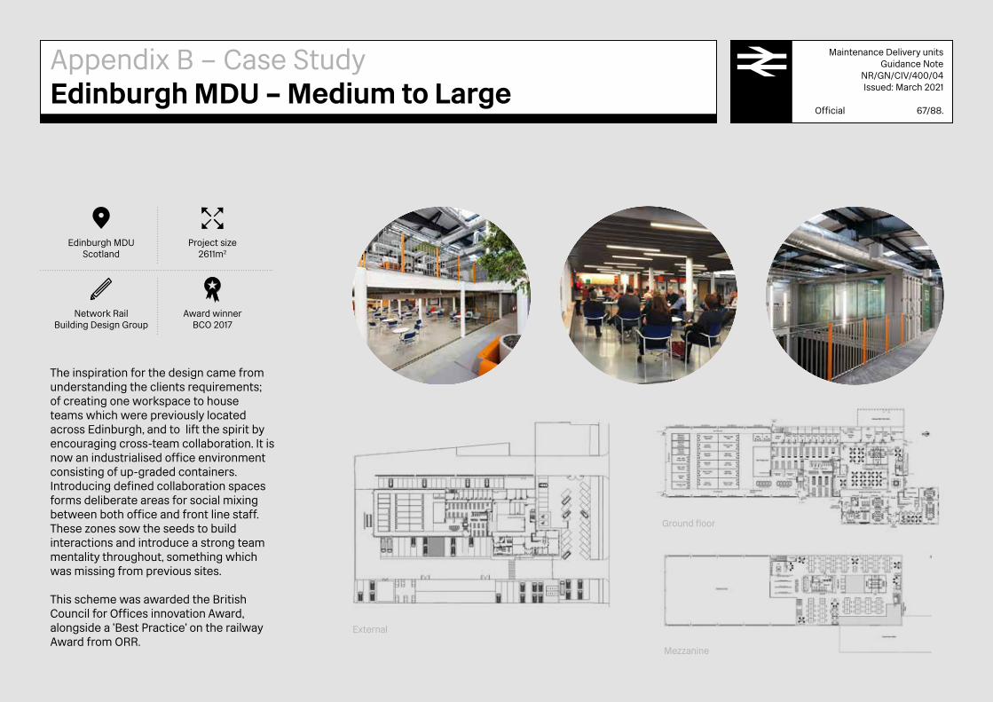
Maintenance Delivery unitsGuidance Note
NR/GN/CIV/400/04Issued: March 2021
Official 67/88.
The inspiration for the design came from understanding the clients requirements; of creating one workspace to house teams which were previously located across Edinburgh, and to lift the spirit by encouraging cross-team collaboration. It is now an industrialised office environment consisting of up-graded containers. Introducing defined collaboration spaces forms deliberate areas for social mixing between both office and front line staff. These zones sow the seeds to build interactions and introduce a strong team mentality throughout, something which was missing from previous sites.
This scheme was awarded the British Council for Offices innovation Award, alongside a 'Best Practice' on the railway Award from ORR.
Project size2611m2
Award winnerBCO 2017
Edinburgh MDUScotland
Network RailBuilding Design Group
Ground floor
External
Mezzanine
Appendix B – Case StudyEdinburgh MDU – Medium to Large

Maintenance Delivery unitsGuidance Note
NR/GN/CIV/400/04Issued: March 2021
Official 68/88.
Capacity 414 staff
Ebervale MDUWales
Network RailDesign Delivery (NRDD)
"The MDU shall reduce its carbon footprint and operational costs through the utilisation of modern construction materials, energy efficient technologies and on-site generation. The route energy and carbon reduction funds are to be utilised for these elements". (Extract of the remit)
The new MDU should be a flagship facility for the Wales Route; bringing together various maintenance teams in a purpose-built facility which enhances the working environment of those based there, whilst reducing the energy consumption and carbon emissions. This is the first MDU redevelopment in CP6 and should form the blueprint for future schemes.
Consideration had to be given to the proximity of residential housing. The look and feel of the new depot was to have a less industrial feel in harmony with its vernacular. In addition, a Sustainable agenda gave the project features that included:
→ Green Roof → Suds car park drainage system → SIP Panel construction methodology for speed of
construction and high thermal performance → Locally sourced materials if practical. → Solar panels → Glue laminated superstructure.
The building should have an embodied low carbon approach in line with the aspirations of Network Rail.
Project size4056m2
Section
Mezzanine
Ground floor
Appendix B – Case StudyEbbw Vale MDU – Large ecobuild
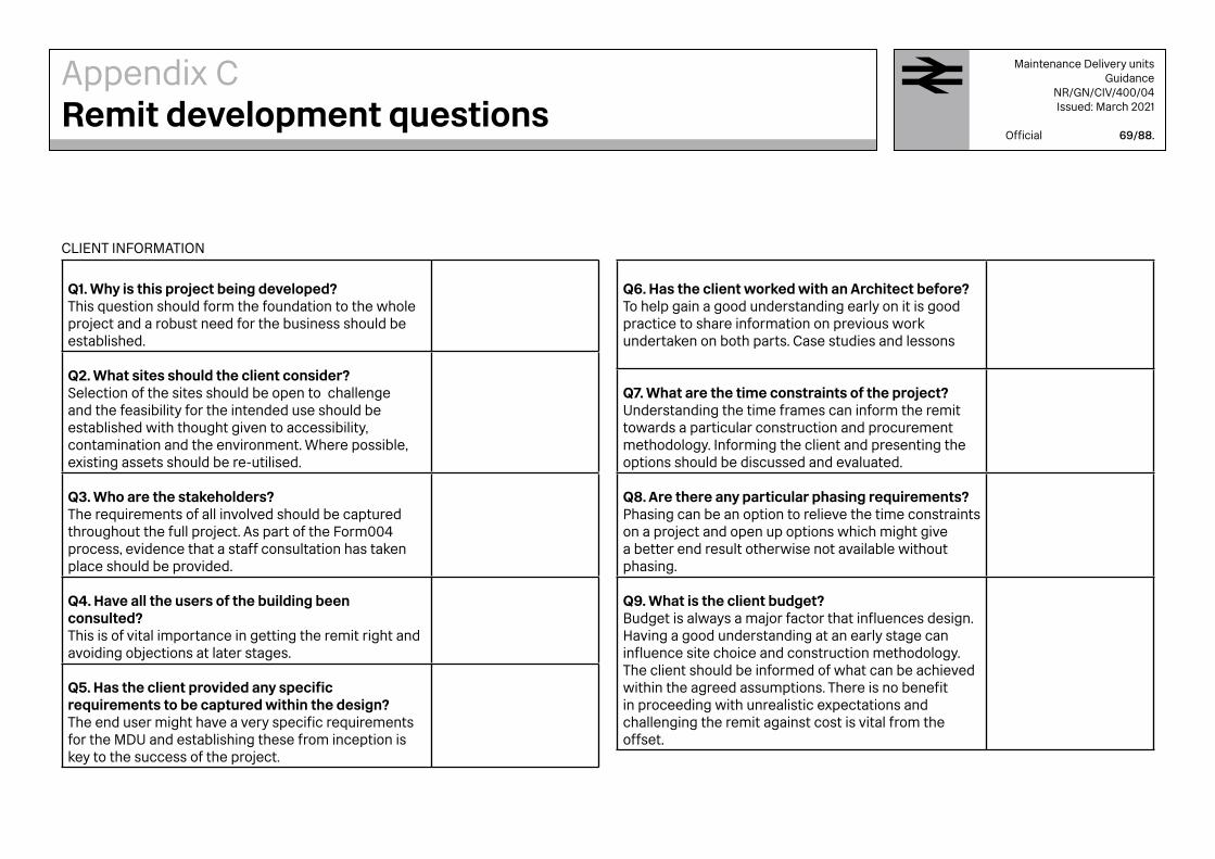
CLIENT INFORMATION
Q1. Why is this project being developed?This question should form the foundation to the whole project and a robust need for the business should be established.
Q2. What sites should the client consider?Selection of the sites should be open to challenge and the feasibility for the intended use should be established with thought given to accessibility, contamination and the environment. Where possible, existing assets should be re-utilised.
Q3. Who are the stakeholders?The requirements of all involved should be captured throughout the full project. As part of the Form004 process, evidence that a staff consultation has taken place should be provided.
Q4. Have all the users of the building been consulted?This is of vital importance in getting the remit right and avoiding objections at later stages.
Q5. Has the client provided any specific requirements to be captured within the design?The end user might have a very specific requirements for the MDU and establishing these from inception is key to the success of the project.
Q6. Has the client worked with an Architect before? To help gain a good understanding early on it is good practice to share information on previous work undertaken on both parts. Case studies and lessons
Q7. What are the time constraints of the project?Understanding the time frames can inform the remit towards a particular construction and procurement methodology. Informing the client and presenting the options should be discussed and evaluated.
Q8. Are there any particular phasing requirements?Phasing can be an option to relieve the time constraints on a project and open up options which might give a better end result otherwise not available without phasing.
Q9. What is the client budget?Budget is always a major factor that influences design. Having a good understanding at an early stage can influence site choice and construction methodology. The client should be informed of what can be achieved within the agreed assumptions. There is no benefit in proceeding with unrealistic expectations and challenging the remit against cost is vital from the offset.
Appendix CRemit development questions
Maintenance Delivery unitsGuidance
NR/GN/CIV/400/04Issued: March 2021
Official 69/88.

BASIC DESIGN FACTORS
Q10. What is the client looking to achieve with this project?Scrutinise the Key Deliverables within the remit.
Q11. Should any future construction be taken into account now or any infrastructure requirements ?Future proofing the design through awareness is very appropriate to Network Rail projects, as multiple projects could possibly be happening in relation to any site at any one time. The Client should be informed of Network Rails developments within the vicinity of the site.
Q12. How does the proposed building integrate with the existing environment?Landscaping, trees, orientation and climate are some factors that should be considered. Context is vital to how the railway environment might affect the surrounding built environment. This should be demonstrated within the Form 004.
Q13. Is the building listed or within a Conservation area?Will require Listed Building Consent if it is. Infrastructure on Railway land can have historical importance; and where possible and practicable, retention should be considered. There are funds available from the Railway Heritage Trust that can aid important refurbishment works.
Q14. Are there any existing buildings on the proposed site, if so, do they set a precedent for material choice?This is key to how they could be either integrated into the design in a sustainable manner rather than be demolished or left empty.
Q15.What type of materials would the client like to use?Thought should be given to robust and hard-wearing materials, with a view to easy replacement and standardisation if possible.
Q16. Are there any specific design goals? For example, Sustainability targets.These requirements could act as aspirational within the scheme and could be value engineered at a later GRIP stage but should not be negated too early if the benefits are obvious to include within the scheme. Grants for sustainability are available within Network Rail and should be discussed with the project scheme as part of brief development.
Q17. Would they like to include new technologies within the project?Network Rail welcome innovation and ways of improving the way we work, if a client team or a design team has experience or recommendations on how to improve daily working, this is encouraged.
Appendix CRemit development questions
Maintenance Delivery unitsGuidance
NR/GN/CIV/400/04Issued: March 2021
Official 70/88.

OCCUPANTS
Q18. Who will use the building?There are numerous teams with varying requirements working out of Network Rail MDUs. A description can be found in section 1.2.7 and from asking the end user to identify the processes, work patterns and requirements associated with their teams.
Q19. What are the end users requirements?Office staff have completely different requirements to the front line staff and a list of associated spaces should that should be collated, and where possible aligned between the requirements of the varying users. Shared spaces such as toilets, should not be duplicated, if possible.
Q20 Any specific accessibility requirements?Accessibility requirement should be verified through the DIA process and should be compliant with the Equalities Act 2010.
SPACES
Q21. What floors / rooms / spaces are required? Both indoor and outdoor.Look for efficiencies and co-dependencies. Highlight to the client any savings made within the design.
Q22. How would the spaces connect?This is vital in terms of how an MDU functions. Please see section2.1.2.
Q23. Are there specific spatial requirements?HGV turning circles, Forklift trucks, process drivers, manufacturing on site requirements.
Q24. Are there any specific external landscaping requirements from the end users?There might be restrictions on use of certain materials or drainage methods, for example.
Q27. Are there any specific Mechanical or Electrical requirements?Sites are sometimes quite remote with very specialised equipment. Knowledge of the proposed equipment should inform the remit development.
Above is a non-exhaustive list of the questions that should be considered when developing the initial Architectural brief.
Appendix CRemit development questions
Maintenance Delivery unitsGuidance
NR/GN/CIV/400/04Issued: March 2021
Official 71/88.

ServicesThe design should allow for easy access to all the electrical and mechanical services. Where maintenance of building elements (roof, wall, and glazing) may be required, access and security should be integrated into the design.
Plant rooms and services cupboards should be located in easily accessible positions. Such rooms should be dedicated for the equipment that is contained within the dedicated spaces; storage of other items should be prohibited.
Where equipment and services are installed at roof level adequate design and planning should allow that any remedial future maintenance and repairs to the roof fabric are feasible without having to remove the equipment. Removal of items should also be feasible with affecting the water tightness of the roof finishes.
Use CFCs (Chlorofluorocarbons) or HCFCs (Hydro-chlorofluorocarbons) is prohibited, nor any products whose production involves the use of these materials.
HEATING LEVELS:
Heating systems should comply with:
→ The Building Regulations; Approved Document L2A (latest amendment)
→ The Fuel and Electricity (Heating) (Control) order (1974) as amended
ENERGY EFFICIENCY
All proposed MDUs should meet the requirements of the Building Regulations 2000, Approved Documents L2A and L2B (2006 edition) or their equivalent in Building Standards (Scotland) Regulations, and any subsequent statutory amendments. The primary aim of the energy concept is to reduce the development’s carbon footprint by achieving optimal environmental conditions with a minimal energy demand through:
→ Highly insulated and tightly sealed façades with operable windows,
→ Optimized daylight utilisation through building form, glazing and light re-direction elements,
→ Buffer zones - such as locating service and circulation areas on the North and east elevations to insulate the interior and harvest solar energy and solar shading
High-performance building-integrated systems, including:
→ Slab-embedded radiant heating / cooling. → Mechanical ventilation incorporating exhaust air
heat recovery. → 100% outdoor air displacement ventilation.
Natural sources, including:
→ Natural ventilation for fresh air and/or cooling. → Façade-integrated photovoltaic systems that
capture solar energy. → Wind power where feasible.
PLANT OPERATING CONDITIONS
All plant items should; → Be rated for operation in the environment in which
they are to be located. → Conform with CIBSE recommendations.
LIFTS
The following references should be followed:
→ The Lifting Operations & Lifting Equipment Regulations 1998 (LOLER)
→ The Lift Regulations (95/16/EC)1997 → EN81 suite of standards: Construction and
Installation of Lifts → BS8300: Code of Practice for the Design of
Buildings for Disabled Access → BS9999: Code of Practice for fire safety in the
design, management and use of buildings.
Appendix DServices Design Parameters
Maintenance Delivery unitsGuidance
NR/GN/CIV/400/04Issued: March 2021
Official 72/88.

ACOUSTIC STANDARDS
The level of hearing is expressed in decibels from 0dB, (the threshold of hearing) to 140dB (the threshold of pain). . Ambient noise levels in spaces when they are unoccupied should not exceed the following:
→ Small consulting rooms = 50 dBA → Large Offices = 45/50 dBA → Private Offices = 40-45 dBA → Small Classrooms = 40 dBA → Large Lecture Rooms = 35 dBA → Canteen/Kitchen/Café Areas = 50 dBA
(Source; British Standards, BS 8233:1999)
Below are Maximum Background Noise Levels emanating from Plant / Building Services Equipment expressed in Noise Reduction levels (NR):
→ Small Offices (Up to 8-persons) NR 30 → Offices (Over 8-persons) NR35 → Reception Areas, corridors . NR40 → Kitchens & computer rooms NR45
(These compliment the acoustic standard referenced above.)
TESTING, COMMISSIONING AND OPERATION OF THE BUILDING:
The building services systems and their associated controls should provide effective monitoring, control and performance of all the mechanical and electrical services.
Heating, cooling and ventilation systems should have controls systems that provide efficient and economical use of energy to achieve compliance with the building regulations. They should also be arranged so that their operations do not conflict in any way with each other.
The Design Parameters should be: → CIBSE Guide B – Heating, Ventilation, Air
Conditioning and Refrigeration. → CIBSE Guide H – Building Control Systems. → CIBSE Commissioning Code C: Automatic Controls → Building Regulations Part L2
SYSTEMS SET-UP:
All heating, ventilation and cooling systems should be designed and specified to provide that building fabric protection and system frost protection is provided: Building Protection Set Point for heating should always come on Internal temperature: 10°C Systems Frost Protection Set Point for heating should always come on: Outside Air Temp: 3°C
OPERATION & MAINTENANCE OF THE FINISHED BUILDING RECORD DOCUMENTS:
To satisfy the provisions of the Health and Safety at Work Act the Employer should not accept handover of the installations until full and adequate information concerning the installations is in the possession of his operating and maintenance staff.
Record Documents should be provided as part of the Works. All manuals documentation and record drawings should be provided in both hard copy and electronic form.
FORMAT OF RECORD DOCUMENTS:
Manuals should be supplied in Microsoft Office Word 2003 format and CAD drawings format. System records and full documentation should include:
→ Record Drawings and Schedules → Plant room and switch room drawings, schedules
and schematics. → Operating and Maintenance Manuals. → Blank maintenance logs → Building log book to comply with the Building
Regulations Part L2, Conservation of → Fuel and Power 2000.
Appendix DServices Design Parameters
Maintenance Delivery unitsGuidance
NR/GN/CIV/400/04Issued: March 2021
Official 73/88.

HAND OVER PROCESS: TRAINING OF EMPLOYER'S STAFF:
The specification should include a requirement for demonstration of the purpose, function and operation of the installations including all items and procedures listed in the Operation and Maintenance Manual. This training / demonstration should be given to the Employer's maintenance staff and operational staff.
HOT AND COLD WATER
Incoming water mains should be routed into the building via an external water meter and terminated at low level via an isolating valve in an accessible plant room. The mains cold water distribution system should be specified with thermally insulated copper pipe-work which should routed around the building to serve all appliances including the following, as applicable:
→ Heating system pressurisation equipment → Kitchen equipment → WCs → Urinals → Tea Point → First Aid Room → Hot water generators → Showers → Wash hand basins
Design Parameters should be → Design in accordance with BS6700. → All water fittings and materials should be specified
as listed in the Water Fittings and Materials Directory published by WRAS.
→ Hot water storage/flow temperature = 60 °C → Hot water return temperature = 55 °C
WATER TREATMENT:
Water supply should have in-line electromagnetic water conditioner(s) on the mains water connections to all hot water heating equipment, including showers.
GAS SUPPLY
If required for heating system purposes, a natural gas supply system should be specified in accordance with the design parameters below, with a suitably sized meter contained in a purpose made and secure external gas meter housing. The gas supply should be installed to serve the heating system boilers with a gas solenoid valve linked to the fire alarm system and an emergency knock-off button in the plant room. Design Parameters should be:
→ British Gas Technical Memorandum → CIBSE Guide B
Gas distribution system should convey: natural gas at a nominal working pressure of 21 mBar at meter. Pressure drop to final connection should not be more than 100Pa. Working temperature should be ambient; and carbon steel pipes should comply with BS 1387.
LIGHTNING PROTECTION
A risk assessment should be carried out to establish if lightning protection is required. The lightning protection system should protect the building and comply with BS EN 62305 AND BS 7671. All metallic parts of the structure should be linked in accordance with BS EN 62305 to form a complete lightning protection network. Conductors should be with horizontal air terminations and earth electrodes for lightning protection. Air terminations should be self-supporting.
Conductor covering colour should match the building fabric cladding colour.
Appendix DServices Design Parameters
Maintenance Delivery unitsGuidance
NR/GN/CIV/400/04Issued: March 2021
Official 74/88.

Maintenance Delivery unitsGuidance
NR/GN/CIV/400/04Issued: March 2021
Official 75/88.
200
200
200
1080
550
M
DWBINBINZIPZIP
REF
T C S150Ø 150Ø
TDSD
CONCEALEDWASTE BINS.SEE NBS,N12 440N10
HARD SURFACE WORKTOP WITH 150MM ØDIAMETER WASTE BIN HOLES.SEE NBS,N10 110N10 200N12 320
SEMI COMMERCIAL SINKSEE NBS,N12 380
LED DOWNLIGHTING
1115
200 200 200 770 530 700
920
MINIMUM OF1200MM(W)X750MM(H)
X650MM(D)
3NO. 550X200mmSHELVESSEE NBS,N12 410N10 110
M&E CONTAINEDBEHIND CUPBOARDS
DOOR HANDLES TO CUPBOARDSREFRIGERATOR DOORS TO CONTRASTCOLOUR OF DOOR
REFDWBINZIPSDTDMTCS
Refrigerator
Dishwasher
Waste BIN
Hydro Tap, Zip Tap
Soap Dispenser
Towel Dispenser
Microwave
Tea
Coffee
Sugar
1. ALL DIMENSIONS IN MILLIMETRES UNLESS NOTED OTHERWISE
DESIGNERS
SAFETY HEALTH ANDENVIRONMENTAL INFORMATION
LEGEND/NOTES
REV DATE DESCRIPTION OF REVISIONS DRAWN CHK'D APPR'D
STATUS
PROJECT:
DRAWING TITLE
DESIGNED
SCALE(S) AT A1 SHEET SIZE 841 X 594
DRAWING NUMBER REVISION
SIGNED
SIGNED
ELR & MILEAGE
SIGNED
SIGNED DATE
DATE
DATE
DATE
ALTERNATIVE REFERENCE
APPROVED
CHECKED
DRAWN
NETWORK RAIL DNA 2016
TYPICAL KITCHENETTE PLAN & SECTION
1:10
PROJECT_NUM
CLIENT
TYPICAL KITCHENETTE SECTIONSCALE 1 :10
TYPICAL KITCHENETTE PLANSCALE 1 :10
1000mm8006004002000
SCALE 1:10
P01
Kitchenette
Equipment Checklist
Hydro tap — providing hot and cold water
Large format larder fridge
Integrated recycling
Supplied towel/soap dispensers
First aid box
Noticeboards
Storage for personal items
Semi commercial dishwasher
Sink with drainer and mixer tap
Storage for crockery and cutlery
Storage for supplied tea/coffee/sugar
Typical drawings are for illustrative reference only
Appendix ETypical Drawings: Kitchenette
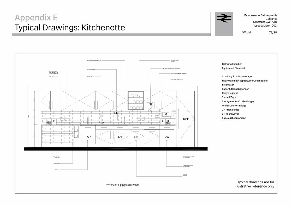
Maintenance Delivery unitsGuidance
NR/GN/CIV/400/04Issued: March 2021
Official 76/88.85
055
070
1
2300
M
DWBINTAPTAP
REF
TD
SD
T C S
Commercial Cabinet Fridge and fascia board.
Commercial Dishwasher and fascia board.
Concealedwaste bins.
OVERHEAD STORAGE CUPBOARD
COMMERCIAL MICROWAVE.
T C S
3NO. 550X200mm SHELVES
KITCHENETTE WRAP AROUND
SOAP DISPENSER
MIXER TAP
Wall tiling and splash back
Skirting Board
Hydro Tap
CLEAR PERSPEX FOR COFFEE, TEA& SUGAR DISPENSERS
SHELVING
CONCEALED PAPER TOWEL DISPENSER
REF
DW
BINTAPSDTDMTCS
Refrigerator
Dishwasher
Waste BIN
Hydro Tap
Soap Dispenser
Towel Dispenser
Microwave
Tea
Coffee
Sugar
1. ALL DIMENSIONS IN MILLIMETRES UNLESS NOTED OTHERWISE
1000mm8006004002000
SCALE 1:10
DESIGNERS
SAFETY HEALTH ANDENVIRONMENTAL INFORMATION
LEGEND/NOTES
REV DATE DESCRIPTION OF REVISIONS DRAWN CHK'D APPR'D
STATUS
PROJECT:
DRAWING TITLE
DESIGNED
SCALE(S) AT A1 SHEET SIZE 841 X 594
DRAWING NUMBER REVISION
SIGNED
SIGNED
ELR & MILEAGE
SIGNED
SIGNED DATE
DATE
DATE
DATE
ALTERNATIVE REFERENCE
APPROVED
CHECKED
DRAWN
CLIENT
PROJECT_NUM
APPROVED
DESIGNED
CHECKED
DRAWN
TYPICAL KITCHENETTE ELEVATIONSCALE 1 :10
NETWORK RAIL DNA 2016
TYPICAL KITCHENETTE ELEVATION
1:10
P01
Catering Facilities
Equipment Checklist
Crockery & cutlery storage
Hydro tap (high capacity) serving hot and
cold water
Paper & Soap Dispenser
Recycling bins
Sinks & Taps
Storage for tea/coffee/sugar
Under Counter Fridge
2 x Fridge units
2 x Microwaves
Specialist equipment
Typical drawings are for illustrative reference only
Appendix ETypical Drawings: Kitchenette

Maintenance Delivery unitsGuidance
NR/GN/CIV/400/04Issued: March 2021
Official 77/88.
Shower face plate .
300mmRainshower head with 400mm wall arm
Cubical with IPS system
Trough urinal in stainless steel
Wall mounted WC.
617
1084
Lockers
New/cleanPPE shelfstorage
1600x900mmLow profile rectangular shower tray
Airblade hand dryer
Toughened safety glass mirror with concealed fixing bracket to create flush finish to tiling.
Stainless steel trough with integrated thermostat sensor
wall tiles
Wall mounted WC
Cubical with IPS system and accessible panels
933
424
2000
2000
Low profile rectangular shower tray
Doors to be provided to shower cubicles with hooks matching shower face plate finish. Doors to match Toilet cubicle doors.
Lock 9261/2hr
1006x2093 Lock 9261/2hr
1006x2093
PL1000
A
D
B
C
EDINBURGH MDU
SHOWER & LOCKER ROOM DETAILS
SHOWER AND TOILET AREA PLAN
ELEVATION DELEVATION C
ELEVATION BELEVATION A
CUBICLE ELEVATION A CUBICLE ELEVATION BTypical drawings are for
illustrative reference only
Appendix ETypical Drawings: Shower & WC

Maintenance Delivery unitsGuidance
NR/GN/CIV/400/04Issued: March 2021
Official 78/88.
Min
125
0
Min
210
0
Min
200
400
1700
SHOWER MIXER
FIXED AND ADJUSTABLESHOWER HEADS
1. ALL DIMENSIONS IN MILLIMETRES UNLESS NOTED OTHERWISE
P01 XX/XX/XX XXXXXX XXX XXX XXX
0 20 40 60 80 100mm
SCALE 1:1
Infrastructure ProjectsBuildings & CivilsDesign GroupYorkYork I.C.C.Leeman RoadYorkYO26 4ZDTel: 033 085 49683
DESIGNERS
THE HAZARDS AND RISKS ASSOCIATED WITH THE WORKSSHOWN ON THIS DRAWING AND DESCRIBED IN THE SCHEDULEOF WORKS ARE CONSIDERED TO BE WITHIN THE REASONABLE,NORMAL AND ACCEPTABLE LIMITS FOR GENERAL BUILDINGAND MAINTENANCE WORKS. PLEASE REFER TO DESIGNERRISK ASSESSMENTDOCUMENT REF:
SAFETY HEALTH ANDENVIRONMENTAL INFORMATION
LEGEND/NOTES
REV DATE DESCRIPTION OF REVISIONS DRAWN CHK'D APPR'D
STATUS
PROJECT:
DRAWING TITLE
DESIGNED
SCALE(S) AT A1 SHEET SIZE 841 X 594
DRAWING NUMBER REVISION
SIGNED
SIGNED
ELR & MILEAGE
SIGNED
SIGNED DATE
DATE
DATE
DATE
ALTERNATIVE REFERENCE
APPROVED
CHECKED
DRAWN
BDGXXXX
BDGXXXX/DRG/AXXX P01
FOR DISCUSSION ONLY
BDGXXXX/DRA
XX/XX/XX
XX/XX/XX
XX/XX/XX
XX/XX/XXTypical drawings are for illustrative reference only
Appendix ETypical Drawings: Shower
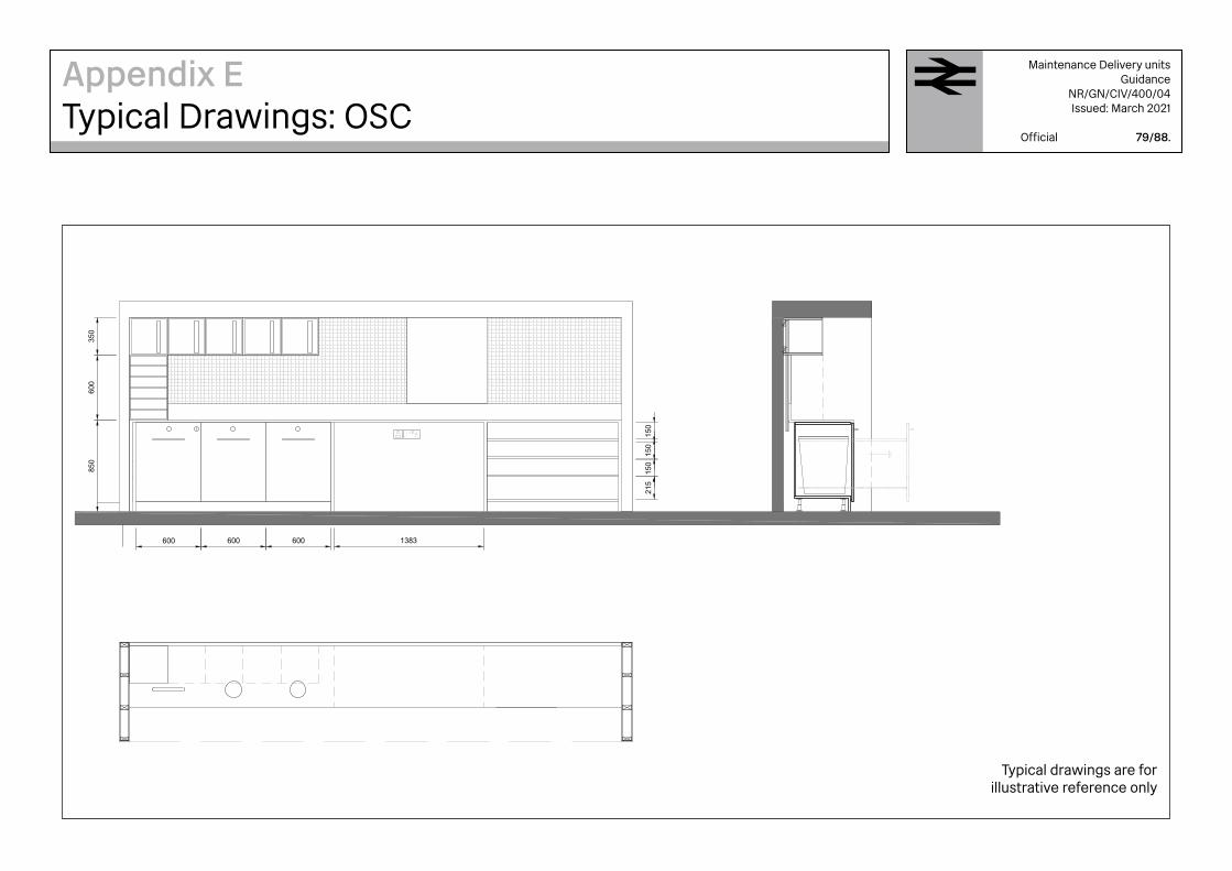
Maintenance Delivery unitsGuidance
NR/GN/CIV/400/04Issued: March 2021
Official 79/88.
600 600 600
850
350
600
215
150
1383
150
150
Infrastructure ProjectsBuildings & CivilsBuilding Design GroupYorkHudson HouseToft GreenYorkYO1 6HPTel: 01904 384 104
DESIGNERS
THE HAZARDS AND RISKS ASSOCIATED WITH THE WORKSSHOWN ON THIS DRAWING AND DESCRIBED IN THE SCHEDULEOF WORKS ARE CONSIDERED TO BE WITHIN THE REASONABLE,NORMAL AND ACCEPTABLE LIMITS FOR GENERAL BUILDINGAND MAINTENANCE WORKS. PLEASE REFER TO DESIGNERRISK ASSESSMENTDOCUMENT REF:
SAFETY HEALTH ANDENVIRONMENTAL INFORMATION
LEGEND/NOTES
REV DATE DESCRIPTION OF REVISIONS DRAWN CHK'D APPR'D
STATUS
PROJECT:
DRAWING TITLE
DESIGNED
SCALE(S) AT A1 SHEET SIZE 841 X 594
DRAWING NUMBER REVISION
SIGNED
SIGNED
ELR & MILEAGE
SIGNED
SIGNED DATE
DATE
DATE
DATE
ALTERNATIVE REFERENCE
APPROVED
CHECKED
DRAWN
DNA FOR OFFICES
BEST
BDG0308
KITCHENETTE & OSC ARRANGEMENTOFFICES
BDG0386/DRG/A003 T01
TENDER ISSUE
1:20
C.KELLY 10/06/15
G.BIMPSON 10/06/15
C.TEARE 10/06/15
G.BIMPSON 10/06/15
1. ALL DIMENSIONS IN MILLIMETRES UNLESS NOTED OTHERWISE
0 0.4 0.8 1.2 1.6 2.0m
SCALE 1:20
Typical drawings are for illustrative reference only
Appendix ETypical Drawings: OSC

Maintenance Delivery unitsGuidance
NR/GN/CIV/400/04Issued: March 2021
Official 80/88.
Ø1500
1x FOLDABLE CHAIR1x 1200x400mm MAX SHOE RACK.1x HIGH LEVEL COAT HOOK RACK.1x 250X250X350 BIN.2X ABLUTIONS STOOLS.1X 1000X600mm HIGH STANDING.STORAGE CUPBOARD.1X PRAYER MATT.1X BI-FOLDING MOVEABLE SCREEN.1X PRAYER CUSHION IN CAMIRAFABRIC NETTLE RANGE COLOURGREEN.1X WUDU WASH BASIN.2X PAPER TOWEL DISPENCER.1X NOTICE BOARD 1500X1000mm2X TAPS OVER WUDU WITH ELBOWLEVER ACTION.2X LOOSE STOOLS
Ø1500
1 X EXAMINATION COUCH1 X PAPER COUCH ROLL(PERFORATED EVERY 35CM)1 X SCARLET COLOURED COTTONBLANKET1 X PILLOW1 X 3-TIER TROLLEY1 X WALL MOUNTED LOCKABLECUPBOARD1 X PEDAL BIN (WITH REMOVABLEPLASTIC LINER)1 X FIRST AID ROOM SIGN1 X FIRST AID GUIDANCE POSTER1 X LOCKABLE WORKSTATION WITH2 X LOCKABLE DRAWERS2X CHAIRS (VITRA SUPPLY)1X 1200X800mm TABLE (VITRASUPPLY)1X IDEAL STANDARD ALTO RANGE50cm BASIN WITH LEVER ACTIONELBOW S/S TAP. FORM 150mm TILESPLASH BACK TO WHB.
P PPRAYER SHELF
482
1168
1800
750
40015
160100
290 STEP ON
STAINLESSSTEELGRATE
OPTIONALSTAINLESS STEELSTOOL
100
RECESSEDMODEL
1.6MM STAINLESSSTEEL ANGLELEGS
305
457
200
1. ALL DIMENSIONS IN MILLIMETRES UNLESS NOTED OTHERWISE
DESIGNERS
SAFETY HEALTH ANDENVIRONMENTAL INFORMATION
LEGEND/NOTES
REV DATE DESCRIPTION OF REVISIONS DRAWN CHK'D APPR'D
STATUS
PROJECT:
DRAWING TITLE
DESIGNED
SCALE(S) AT A1 SHEET SIZE 841 X 594
DRAWING NUMBER REVISION
SIGNED
SIGNED
ELR & MILEAGE
SIGNED
SIGNED DATE
DATE
DATE
DATE
ALTERNATIVE REFERENCE
APPROVED
CHECKED
DRAWN
CLIENT
PROJECT_NUM
TYPICAL RELAXATION ROOM ELEVATION ASCALE 1:25
TYPICAL RELAXATION ROOM PLANSCALE 1:25
TYPICAL RELAXATION ROOM ELEVATION BSCALE 1:25
TYPICAL FIRST AID ROOM PLANSCALE 1:25
SECTION A-A THOUGH WUDUSCALE 1:10
3D OF WUDU
TYPICAL FIRST AID ROOM ELEVATIONSCALE 1:25
1000mm8006004002000
SCALE 1:10
0 0.5 1.5 2.0 2.5m1.0
SCALE 1:25
NETWORK RAIL DNA 2016
TYPICAL MULTI-FAITH AND AID ROOM
1:25 1:10
P01
Typical drawings are for illustrative reference only
Appendix ETypical Drawings: Relaxation & First Aid Room

RECEPTION
MEETINGROOM
ENTRANCE
UP
STORE
MEETING ROOM
STORAGESTORAGE
LOBBY
GLAZING PARTITION
GLA
ZIN
G P
AR
TITI
ON
STORE
* Typical drawings are for illustrative reference only
Appendix ETypical drawings – Reception
Maintenance Delivery unitsGuidance
NR/GN/CIV/400/04Issued: March 2021
Official 81/88.

Transformers L.L. / cables & clips above
DisabledWC
Reception
Cloaks
Lockers
FALL
FALL
MALE WC
FEMALE WC
ChargingRoom 2
Lockers
ChargingRoom 3
RackRackRack
RackRackRack
RackRackRack Rack
Work bench Work bench
ShelfShelf Shelf Tools
Tube cuttingTube Store
Dropper TableTable
Build Area
TubeStore(vert.)
Emergencyeye bath
E & P AREA
TRAINING AREA
Store Controller
COSHH Store
Work bench
Work bench
Work bench
LCLCLC
Grinder
Tool
sN
/B
S & T AREA
CIVILSHOLDING
AREA
P WAYHOLDING
AREA
OLEHOLDING
AREA
S & THOLDING
AREA
E & PHOLDING
AREA
CIVILSS & T S & T S & T S & TS & T
Welding
Forklift turningcircle area
Forklift turningcircle area
Forklift turningcircle area
PPE Store
Calibrationroom
Calibrationroom
Calibrationroom
Rack Rack
Quarantine
Poi
nt H
eatin
g E
lem
ents
Point Heating Elements
Point Heating Elements
E & P
P WAYTECH
P WAYTECHOLE
RackRackRack RackRack Rack
Rack Rack RackRack
RackRackRack Rack Rack
RackRackRack Rack Rack
Rack
Rac
kR
ack
Rac
k
SIG
NA
LIN
G C
AB
LES
OLE
CA
BLE
SOLE RACKING
P WAY RACKING
P WAY RACKING
E & P RACKING
E & P RACKING
P WAY AREA
FEMALEDRYINGROOM
Laun
dry
MedicalRoom
EXAMINATION COUCH
PEDAL BIN WITHREMOVABLE
PLASTIC LINER
LOCKABLEWORKSTATION
WITHLOCKABLEDRAWERS
600X900 MIRROR
Ø1500
WC ConsumablesStore
Glazed screen
Comms
MEETINGROOM
MEETINGROOM
BREAKOUT
ZONE
BREAKOUTWORK SPACE
kITCHENETTE
BENCH SEATING
STA
IR
Gla
zed
scre
en
OSC
RAISEDPLATFORM
WRITE ONBOARD ZONE
BREAKOUT
ZONE
BREAKOUT
ZONE
Lockers
Emergencyeye bath
Emergencyeye bath
RAMP RAMP
CLNRSTORE
UNISEXSHOWER /DIS. WC
2700
2800
MALEDRYINGROOM
Lockers
Laundry
PLANTROOM
Lockers
A A
B
B
H4
H3
H5
H2
* Typical drawings are for illustrative reference only
Colours indicate different team storage areas
Appendix ETypical drawings – Warehouse
Maintenance Delivery unitsGuidance
NR/GN/CIV/400/04Issued: March 2021
Official 82/88.

Appendix FDesign Life Tables – Roof and roof drainage
Maintenance Delivery unitsGuidance
NR/GN/CIV/400/04Issued: March 2021
Official 83/88.
ROOF AND ROOF DRAINAGE – FRAME
DETAIL DESIGN LIFE (years)
CAST IRON FRAME 100
INSITU CONCRETE 80
STEEL FRAME 100
STEEL TRUSS 25
TIMBER FRAME 60
ROOF AND ROOF DRAINAGE – ROOF COVERINGS (continued)
DETAIL DESIGN LIFE (years)
ARTIFICIAL SLATING 70
ASPHALT - PITCHED 35
ASPHALT - FLAT 35
BUILT-UP FELT ROOF (double) 20
BUILT-UP FELT ROOF (triple) 25
CLAY TILES 70
CONCRETE TILES 70
COPPER 60
ROOF AND ROOF DRAINAGE – ROOF COVERINGS
DETAIL DESIGN LIFE (years)
FIBRE CEMENT 25
GALVANISED CORRUGATED STEEL
35
GRP CLADDING 30
LEAD FLASHINGS/SOAKERS/APRONS
35
LEAD SHEET COVERING 35
NATURAL SLATING 70
PATENT GLAZING 30
PLASTIC FASCIA/SOFFIT 20
PROFILES STAINLESS 35
PROFILED METAL - LEAD 35
PROFILED METAL - ZINC 30
PROFILED METAL - COPPER 35
TIMBER FASCIA 20
TIMBER SOFFIT 20
ZINC 60

ROOF AND ROOF DRAINAGE – ROOF STRUCTURE
DETAIL DESIGN LIFE (years)
CONCRETE 80
METAL 40
PLASTIC 20
PROFILED METAL 100
STEEL 100
TIMBER 40
WOOD-WOOL SLATS 50
ROOF AND ROOF DRAINAGE – ROOF-LIGHTS
DETAIL DESIGN LIFE (years)
ALUMINIUM 30
CIRCULAR STEEL FRAME 30
CONCRETE 40
PROPRIETARY UNIT 25
PVC CORRUGATED 25
TIMBER 25
HARDWOOD LOUVRE 30
PATENT GLAZING 30
ROOF AND ROOF DRAINAGE – ROOF DRAINAGE
DETAIL DESIGN LIFE (years)
ALUMINIUM 30
ASPHALT GUTTERS 35
BITUMEN FELT GUTTERS 15
CAST IRON DOWNPIPES 60
CAST IRON GUTTERS 60
CAST IRON GUTTERS & DOWNPIPES
60
FIBRE CEMENT GUTTERS 30
LEAD FLASHINGS/SOAKERS/APRONS
35
LEAD SHEET GUTTERS 35
PRESSED METAL GUTTERS & DOWNPIPES
30
TIMBER GUTTERS 20
UPVC DOWNPIPES 20
UPVC GUTTERS 20
Appendix FDesign Life Tables – Roof and roof drainage
Maintenance Delivery unitsGuidance
NR/GN/CIV/400/04Issued: March 2021
Official 84/88.

WALLS AND FRAMES – EXTERNAL WALLS
DETAIL DESIGN LIFE (years)
INSITU CONCRETE COPING 80
MELANIN FACED CLADDING 30
METAL CLADDING 30
NATURAL STONE 80
PATENT GLAZING 30
PRE-CAST CONCRETE COPINGS 25
RECONSTITUTED STONE 80
RENDERED BLOCK WALL 100
RENDERED PLYWOOD 40
SOLID BLOCK WALL 80
SOLID BRICK WALL 80
TIMBER CLADDING 30
UPVC CLADDING 40
WALLS AND FRAMES – RETAINING WALLS
DETAIL DESIGN LIFE (years)
BRICK 80
CONCRETE 80
CONCRETE BLOCK 80
RENDERED BRICK 80
SHEET PILE 40
STONE 80
TIMBER SLEEPER 25
WALLS AND FRAMES – INTERNAL WALLS AND PARTITIONS
DETAIL DESIGN LIFE (years)
BLOCK/BLOCK CAVITY WALL 80
BRICK 80
CONCRETE 80
CONCRETE SILL 80
DENSE BLOCK 80
GLASS BLOCK 50
METAL CLADDING 30
METAL STUD 50
NATURAL STONE 80
PATENT GLAZING 30
PROPRIETARY PARTITIONS 50
TIMBER CLADDING 40
TIMBER STUD 50
WALLS AND FRAMES – SUPERSTRUCTURE
DETAIL DESIGN LIFE (years)
CONCRETE FRAME 80
STEEL FRAME 100
TIMBER FRAME 60
CONCRETE 80
Appendix FDesign Life Tables – Walls and Frames
Maintenance Delivery unitsGuidance
NR/GN/CIV/400/04Issued: March 2021
Official 85/88.

BREEAM
BS CEEQUAL
CCTV CDMCIBSECRDDfTDIADRRD EIAGRIPHGVIDCIDRIT
Building Research Establishment Environmental Assessment MethodBritish StandardsCivil Engineering Environmental Quality Assessment and Award SchemeClosed Circuit TelevisionConstruction Design ManagementChartered Institution of Building Services EngineersClient Requirements DocumentDepartment for TransportDiversity Impact AssessmentDetailed Route Requirements DocumentEnvironmental Impact AssessmentGovernance of Railway Investment ProjectsHeavy Goods VehiclesInterdisciplinary Design CheckInterdisciplinary Design ReviewInformation Technology
Appendix GGlossary and Acknowledgements
MDUNRNRDD NRTNRITPEPRMPVRRDRRVRSSBRICSRSITSIDOSTfL TSUPS
Maintenance Delivery UnitNetwork RailNetwork Rail Design DeliveryNetwork Rail TelecomsNetwork Rail ITProject EngineerPeople with Reduced MobilityPhotovoltaic panelsRoute Requirements DocumentRoad - Rail VehicleRail Safety Standards BoardRoyal Institute of Chartered SurveyorsRoute Services Information TechnologySecurity In the Design Of StationsTransport for London TOC – Train Operating CompanyTransport ScotlandUninterrupted Power Supply
Maintenance Delivery unitsGuidance
NR/GN/CIV/400/04Issued: March 2021
Official 86/88.
Acknowledgements
This document was produced by Network Rail Design Delivery (NRDD)with the assistance of Network Rail Technical Authority
Photo credits
Network Rail and Network Rail Design DeliveryAll photos
Drawings
Network Rail Design DeliveryAppendix E drawings

Image 42Refurbishment of heritage
Hitchin

400/
04


![ORDER PERMANENTLY FORBIDDING PUBLICATION OF THE … · 1 MLR v NR DC Auckland CIV-2012-004-1034, 9 May 2013 at [25] per Judge Sharp. 2 NR v District Court at Auckland [2014] NZHC](https://static.fdocuments.in/doc/165x107/5f31c8f13e30b162c80c35ab/order-permanently-forbidding-publication-of-the-1-mlr-v-nr-dc-auckland-civ-2012-004-1034.jpg)