
Design Guidelines Traffic - Port Authority of New York and ... · PDF fileOpen road Weaving...
26
LAST UPDATED 12/12/2014 Design Guidelines Traffic
Transcript of Design Guidelines Traffic - Port Authority of New York and ... · PDF fileOpen road Weaving...

LAST UPDATED 12/12/2014
Design Guidelines Traffic

Engineering Department Manual
Traffic — TOC
TABLE OF CONTENTS
Last Updated: 12/12/2014 Page iii
1.0 TRAFFIC DISCIPLINE 1 1.1 OVERVIEW 1
1.1.1 TRAFFIC PLANNING 1 1.1.2 TRAFFIC DESIGN 1 1.1.3 TRAFFIC OPERATIONS 1 1.1.4 TRAFFIC SAFETY 2 1.1.5 INTELLIGENT TRANSPORTATION SYSTEMS 2
2.0 TECHNICAL AND CODE STANDARDS/REGULATIONS 3 3.0 DESIGN CRITERIA AND SPECIAL REQUIREMENTS 4
3.1 PLANNING 4 3.1.1 TRAFFIC ANALYSIS 4
3.1.1.1 Functional Plan Development 4 3.1.2 PEDESTRIAN ANALYSIS 5 3.1.3 PARKING ANALYSIS 5
3.2 DESIGN 5 3.2.1 CONSTRUCTION STAGING 5 3.2.2 MAINTENANCE AND PROTECTION OF TRAFFIC (MPT) 5
3.2.2.1 Typical Closures 5 3.2.3 TRAFFIC (PERMANENT CONSTRUCTION) 9
3.2.3.1 Signing 9 3.2.3.2 Pavement Markings 10 3.2.3.3 Guiderail 11 3.2.3.4 Barriers 11 3.2.3.5 Impact Attenuators 11 3.2.3.6 Delineation Devices and Markers 11 3.2.3.7 ITS 12 3.2.3.8 Dynamic Message Signs 12 3.2.3.9 Traffic Signals 12 3.2.3.10 Pedestrian And Bicycle Accommodations 12 3.2.3.11 Roadway Access Management 12
3.3 COST ESTIMATE 12 3.3.1 MAINTENANCE AND PROTECTION OF TRAFFIC 12 3.3.2 PERMANENT TRAFFIC 12
4.0 DETAILS, NOTES, AND CUSTOM SPECIFICATIONS 13 4.1 TRAFFIC STANDARD DETAILS 13
4.1.1 TD010 – LEGEND, NOTES AND ABBREVIATIONS 13 4.1.2 TD020 – TRAFFIC SIGNALS 13 4.1.3 TD030 – SIGN MOUNTING DETAILS 14 4.1.4 TD040 – SIGN LAYOUT DATA 15 4.1.5 TD 050 – PAVEMENT MARKINGS 16 4.1.6 TD060 – DELINEATION DEVICES AND MARKERS 16 4.1.7 TD070 – PERMANENT IMPACT ATTENUATORS 16 4.1.8 TD100 – MAINTENANCE OF TRAFFIC DEVICES 16
4.1.8.1 Channelizing Devices TD100 16 4.1.8.2 Temporary Barrier TD110 17 4.1.8.3 Temporary Impact Attenuators TD120 17 4.1.8.4 Construction Signs TD130 17 4.1.8.5 Typical Lane Closure and Reduction Details and Notes TD140 17 4.1.8.6 Miscellaneous Devices TD150 17
4.1.9 TD200 – PERMANENT BARRIERS 17

Engineering Department Manual
Traffic — TOC
TABLE OF CONTENTS
Last Updated: 12/12/2014 Page iv
4.1.10 TD300 – GUIDERAIL AND END TREATMENTS 18 4.1.11 TD410 – TRAFFIC CALMING DEVICES 19 4.1.12 TD 500 – INTELLIGENT TRANSPORTATION SYSTEMS 19
4.2 DIVISION 1 MOT SPECIFICATION 21 4.3 STANDARD SPECIFICATIONS 21 4.4 C-SPECIFICATIONS 22 4.5 HOURS OF WORK 22 4.6 WORK RESTRICTION/CONDITIONS AND PRECAUTIONS 22 4.7 GENERAL NOTES 22 4.8 PERMANENT TRAFFIC ITEMS 22
5.0 REFERENCE MATERIALS 23 5.1 OPERATING AND MAINTENANCE STANDARDS 23
5.1.1 PABT WORK AREA PROTECTION (O&M 73) 23 5.1.2 ROADWAY AREA PROTECTION (O&M 20) 23 5.1.3 TESTING ROADWAYS FOR SKID RESISTANCE (O&M 46) 23 5.1.4 TUNNEL ROADWAY AREA PROTECTION (O&M 37) 23
5.2 LANE CLOSURE GUIDELINES 23 5.2.1 AVIATION 23 5.2.2 TB&T 23 5.2.3 PORT COMMERCE 23
5.3 STANDARD HIGHWAY SIGNS 23 5.4 USDOT ITS STANDARDS 23 5.5 TRAFFIC ENGINEERING HANDBOOK 23 5.6 FLAGGER’S HANDBOOK 23 5.7 PORT AUTHORITY ROADWAY ACCESS MANAGEMENT GUIDELINES 23

Engineering Department Manual
Traffic — Overview
Last Updated: 12/12/2014 Page 1
1.0 TRAFFIC DISCIPLINE
1.1 OVERVIEW
These guidelines are provided as an overview of the Port Authority’s design standards. Design details and associated documents outlined in these documents will be provided to the designer as required. The Guidelines shall not replace professional design analyses nor the Guidelines are intended to limit innovative design where equal performance in value, safety, and maintenance economy can be demonstrated. The design team shall be responsible for producing designs that comply with the Guidelines in addition to all applicable codes, ordinances, statutes, rules, regulations, and laws. Any conflict between the Guidelines and an applicable code, ordinance, statute, rule, regulation, and/or law shall be addressed with the respective functional chief. The use and inclusion of the Guidelines, specifications, or example drawing details as part of the Contract Documents does not alleviate the design professional from their responsibilities or legal liability for any Contract Documents they create. It is also recognized that the Guidelines are not universally applicable to every project. There may be instances where a guideline may not be appropriate. If the design professional believes that a deviation from the Guidelines is warranted, such a deviation shall be submitted in writing for approval to the respective functional chief. The Traffic Engineering Discipline is part of the Engineering/Architecture Design Division (EADD) of the Engineering Department. As expanded upon below, the Traffic Engineering Discipline is organized into five functional groups: Traffic Planning, Traffic Design, Traffic Operations, Traffic Safety, and Intelligent Transportations Systems. Roadway Access Management is a technical tool that is included within the first four of these functional groups.
1.1.1 TRAFFIC PLANNING
Perform transportation planning services and the functional planning of new infrastructure investments and improvements to existing vehicular and pedestrian facilities by performing surveys and developing and maintaining state-of-the-art traffic forecasting, simulation, and trip assignment computer models.
1.1.2 TRAFFIC DESIGN
Perform traffic engineering design services to support the Engineering Department’s commitment to capital and operating major works programs by serving as a Lead Engineer/Architect or in a support (Task Leader) capacity to other engineering disciplines.
Tasks include:
Contract preparation. Stage IV construction coordination. Shop drawing reviews. Field support in auditing and implementing Maintenance of Traffic plans during construction. Traffic Signal turn-on and Final inspection checklist in coordination with the Construction
Management Division (CMD) and Electrical Facility. TAA reviews.
1.1.3 TRAFFIC OPERATIONS
Perform day-to-day traffic engineering services to provide a safe and reliable transportation system through the practice of Service Engineering. Work with facility staff to resolve traffic flow, control, capacity, levels of service, access, egress, and parking issues. Determine the design, type, size, and location of all traffic signs, signals, pavement markings, roadside appurtenances, and similar devices.

Engineering Department Manual
Traffic — Overview
Last Updated: 12/12/2014 Page 2
1.1.4 TRAFFIC SAFETY
Perform traffic engineering services through a Traffic Safety Improvement Program to plan, implement, and evaluate traffic safety improvements to minimize the frequency, severity, and risk of vehicle crashes. Ensure due diligence on the part of the Port Authority of New York & New Jersey to provide a safe environment for vehicles and pedestrians.
1.1.5 INTELLIGENT TRANSPORTATION SYSTEMS
Manage the agency’s ITS program in accordance with the implementation roadmap to help deliver the ITS Strategic Plan mission through the use of transportation technologies. Perform ITS planning, design, and construction and operational support services to improve operational efficiency and help optimize the use of available transportation system network capacity.

Engineering Department Manual
Traffic — Technical & Code Standards/Regulations
Last Updated: 12/12/2014 Page 3
2.0 TECHNICAL AND CODE STANDARDS/REGULATIONS
Federal Highway Administration: Manual on Uniform Traffic Control Devices (MUTCD), latest edition
American Association of State Highway and Transportation Officials (AASHTO): A Policy on Geometric Design of Highways and Streets – “AASHTO Green Book,” latest edition
Roadside Design Guide, 4th Edition, AASHTO, 2011
Standard Highway Signs, FHWA, 2004
Highway Capacity Manual (HCM), Transportation Research Board (TRB), 2010
Public Right of Way Accessibility Guidelines (PROWAG), 2013
Guide for the Planning, Design, and Operation of Pedestrian Facilities, AASHTO, 2004
Americans with Disabilities Act Standards for Accessible Design
Guide for the Development of Bicycle Facilities, AASHTO, 4th Edition, 2012
Pedestrian Planning and Design, John Fruin, Ph.D., 1971
NYC CEQR Technical Manual, NYC Mayor’s Office of Environmental Coordination, 2014
Station Planning and Design Guidelines, MTA New York City Transit, 2006
Transit Capacity and Quality of Service Manual, 3rd
Edition, Transportation Research Board (TRB), 2013
CADD Standard Manual (PA)
Tenant Construction Review Manual (PA)
Sustainable Design Guidelines (PA)
Traffic Signal Design and Preparation Guidelines (PA)
Airport Roadway Sign Design Manual (PA)
Roadside and Median Barrier Design Guide (PA) DRAFT
ITS Design Guidelines (PA)
Roadway Access Management Guidelines (PA)

Engineering Department Manual
Traffic — Design Criteria & Special Requirements
Last Updated: 12/12/2014 Page 4
3.0 DESIGN CRITERIA AND SPECIAL REQUIREMENTS
3.1 PLANNING
3.1.1 TRAFFIC ANALYSIS
The design team should familiarize themselves with the material in Port Authority Roadway Access
Management Guidelines (See Section 3.2.3.11). Of particular importance is chapter 2, “The Role of
Roadway Access Management in Port Authority Business Practices.”
3.1.1.1 FUNCTIONAL PLAN DEVELOPMENT
Generally Produced in Stages I and II:
1. Determine design year (usually 20 years into future).
2. Determine design hourly volume (DHV).
3. On existing roads obtain current traffic volume and factor in growth factors. Consider:
Local traffic
PA facility traffic
New facilities
Local
PA
For new facilities or roadways determine trip generations
4. Select level of service for design (usually C or D).
5. Compare DHV to existing capacity (for not only the ultimate configuration but also for intermediate construction stages):
Open road
Weaving areas
Intersections
Signalized
Unsignalized
6. Develop conceptual plan to overcome capacity shortfall:
Improved traffic management systems (improve existing conditions)
Rerouting traffic
Improved signing and striping
Traffic/parking restrictions
Widening
Signalization
Revise existing
New

Engineering Department Manual
Traffic — Design Criteria & Special Requirements
Last Updated: 12/12/2014 Page 5
Roadway Access Management (consistent with PA Roadway Access Management Guidelines and coordinated with PA Engineering Department)
7. Prepare functional plan to show:
Existing major elements (curbs, barriers, signals, etc.) to remain, to be relocated, and to be changed
New elements
Existing elements to be relocated
Pavement marking to clearly show number of traffic lanes
Roadway layout throughout the area of concern and where it meets existing
North arrow
8. Finalize functional plan to show:
Traffic volumes (DHV)
Roadway widths
Traffic signals
Traffic signs (regulatory, warning, directional)
North arrow
In general, before proceeding into the next phase, secure Line Department/ Facility concurrence with results so far.
3.1.2 PEDESTRIAN ANALYSIS
Under Development
3.1.3 PARKING ANALYSIS
Under Development
3.2 DESIGN
3.2.1 CONSTRUCTION STAGING
Under Development
3.2.2 MAINTENANCE AND PROTECTION OF TRAFFIC (MPT)
3.2.2.1 TYPICAL CLOSURES
A work zone is an area where road user conditions are changed by the use of temporary traffic control devices, flaggers, or other authorized personnel due to construction activity. Standards and guidelines for the maintenance and protection of traffic (MPT) in work zones are found in the Manual on Uniform Traffic Control Devices (MUTCD) and the Port Authority Standard Details Section TD 100.
All roadway construction projects shall include a plan for the MPT. These plans shall provide:
A high level of safety for workers and the traveling public.
Acceptable levels of service and minimize congestion.
An acceptable work area for the contractor.
Cost efficiency while maintaining safety at all times.

Engineering Department Manual
Traffic — Design Criteria & Special Requirements
Last Updated: 12/12/2014 Page 6
Guidelines for the design, use, installation, and operation of traffic control devices are established by the MUTCD. The latest edition of the MUTCD is available online at www.mutcd.fhwa.dot.gov. All traffic control devices shown in the Port Authority Standard Details may be used for work zone traffic control.

Engineering Department Manual
Traffic — Design Criteria & Special Requirements
Last Updated: 12/12/2014 Page 7
Traffic control devices include but are not limited to:
Signs
Signals
Pavement Markings
Delineation Devices
Hand-Held Signaling Devices
ITS Elements
3.2.2.1.1 Construction Signs
When choosing signs for work zones, the following should be considered:
A. Choose signs that are appropriate and that accurately describe the roadway conditions.
B. Choose the message signs according to what action the driver needs to take.
C. Use larger signs when greater visibility is desired. For example, high speeds or large volumes.
D. Consider using smaller signs in narrow medians if larger signs will overhang the adjacent travel lane.
3.2.2.1.2 Sign Placement
A. Location of advance warning signs should consider exiting and entering traffic. It is generally not desirable to start a warning sign series upstream from a major exit or intersection, except when it is desirable to divert traffic off the route at that point.
B. Advance warning signs must be adequately spaced to provide recognition and legibility. On roadways with high speeds and volumes, signs must be spaced at least 500 feet apart.
C. Warning signs must be located to provide adequate visibility distance to drivers. They must not be blocked by foliage, roadway features, or other signs and traffic control devices nor interfere with other signs.
D. Warning signs should not be located where glare from light sources behind the sign may reduce visibility.
E. Actual distance from a warning sign to the condition should be close to the stated distance on the sign and in accordance with the MUTCD. However, positioning of the sign to enhance visibility and avoid conflicts with other traffic control devices and roadway features is more important than precise agreement with the stated distance.
3.2.2.1.3 Portable Variable Message Signs
Portable variable message signs (VMS) are to be used as supplemental, temporary work zone warning devices and for lane and roadway closures. VMS may supplement signing in a work zone but cannot be used to replace regulatory or warning signs. They may also be used in lieu of or to supplement guide signs.
The following guidelines are provided to help the designer determine whether or not to select VMS for use in work areas:
A. Variability—The flexibility of the VMS allows various messages to be displayed rather than providing an equal number of fixed-message signs.

Engineering Department Manual
Traffic — Design Criteria & Special Requirements
Last Updated: 12/12/2014 Page 8
B. Real Time Information—VMS can be reprogrammed to provide real-time traffic information, such as changes in detour routes and diversions.
C. Attention—VMS command more attention than standard signs. This aspect may be especially useful in complicated detour routes and diversions as well as night time work. VMS also stand out if a large number of signs are already present in the area.
D. Type—The specified VMS must be a light emitting diode (LED) type.
3.2.2.1.4 Work Area Details
A. The maximum work area length L occupied by workers on foot shall not exceed 2S as shown in Work Area Detail. Additional contractor vehicles (tightly grouped) may be parked in the closed lane immediately beyond the occupied work area.
B. Signs reading “[RIGHT, CENTER or LEFT[ LANE(S) CLOSED,” as appropriate, shall be installed in the closed lane(s) adjacent to traffic at 500 ft intervals after the initial drum line taper, except between work areas that are not more than 500 ft apart.
C. For work areas that occupy two or more contiguous lanes, each occupied lane must be closed with its own back-up vehicle, at such a location, only the back-up vehicle(s) adjacent to an open traffic lane are required to be equipped with a flashing arrow sign unit (FASU).

Engineering Department Manual
Traffic — Design Criteria & Special Requirements
Last Updated: 12/12/2014 Page 9
Regulatory Approach Speed of Traffic
(miles/hour)
Recommended Sight Distance To Beginning of Channelizing Tapers
Desirable
(Feet)
Minimum
(Feet)
25 525 150
30 625 200
35 725 250
40 825 325
45 925 400
50 1025 475
55 1150 550
60 1275 650
Recommended Taper Length and Spacing for Channelizing Tapers Recommended Spacing Along Tangents
Regulatory Approach Speed
of Traffic
(Miles/hour)
Minimum Taper Ratio in Length
Per Foot of Width
Minimum Taper Length l – For Lane
Widths
Maximum Device Spacing Along
Tapers*
(Feet)
Maximum Device Spacing Along
Tangents
(Feet)
10’ 11’ 12’
25 10.5:1 105 115 125 25 50
30 15:1 150 165 180 30 60
35 20.5:1 205 225 245 35 70
40 27:1 270 300 325 40 80
45 45:1 450 495 540 45 90
50 50:1 500 550 600 50 100
55 55:1 550 605 660 55 110
60 60:1 600 660 720 60 120
65 65:1 650 715 780 65 130
* The maximum device spacing along curves shall be as defined for tapers shown in the table above.
3.2.3 TRAFFIC (PERMANENT CONSTRUCTION)
3.2.3.1 SIGNING
All roadway signs shall be in accordance with the latest version of the MUTCD. Guide signing on airport roadway facilities shall be in accordance with the PA Airport Roadway Sign Design Manual.

Engineering Department Manual
Traffic — Design Criteria & Special Requirements
Last Updated: 12/12/2014 Page 10
3.2.3.2 PAVEMENT MARKINGS
3.2.3.2.1 Typical Parking Layouts
Notes:
Angles between 76° and 89° are not recommended. These angles permit drivers of smaller vehicles to back out and exit the wrong way.
To maintain the same level of service with wider stalls, reduce the Module (M) by 3 inches for each 1 inch additional stall width.
Columns and light poles may protrude into the parking module a combined maximum of 2 ft as long as they do not affect more than 25% of the stalls in that bay.

Engineering Department Manual
Traffic — Design Criteria & Special Requirements
Last Updated: 12/12/2014 Page 11
Small car only stalls (7’-6” wide x 15’-0” long) should only be used at constrained locations or in remnants of space. The number of these stalls should not exceed 15% of the total capacity.
3.2.3.2.2 Accessible Parking Spaces
The minimum number of spaces in compliance with the Americans with Disabilities Act Accessibility Guidelines (ADAAG), September 2002 is:
Total Spaces in Lot Minimum Number of
Accessible Spaces
1 to 25 1
26 to 50 2
51 to 75 3
76 to 100 4
101 to 150 5
151 to 200 6
201 to 300 7
301 to 400 8
401 to 500 9
501 to 1000 2% of Total
1001 and Over 20 plus 1 for each 100 over 1000
Exception: Parking areas on the premises of, or immediately adjacent to, medical services facilities providing treatment for mobility-impaired persons and other similar locations may require a greater number of accessible parking spaces than indicated above. Refer to the applicable accessibility standard.
Parking spaces for use by persons with disabilities shall be the spaces closest to the nearest accessible building or facility entrance on an accessible route.
Two accessible 90° angle parking spaces may share a common access aisle. For acute angled parking, such as 60° parking, or where one-way driveway aisles would prevent vans with passenger side lifts from backing into accessible spaces, an accessible access aisle must be provided for each accessible parking space. Width of access aisles and parking spaces are measured perpendicular to the striping.
For typical layouts of accessible parking spaces see Traffic Standard Details.
3.2.3.3 GUIDERAIL
All guiderail design shall be in accordance with the Roadside and Median Barrier Design Guide (PA)
3.2.3.4 BARRIERS
Traffic barrier design shall be in accordance with the Roadside and Median Barrier Design Guide (PA)
3.2.3.5 IMPACT ATTENUATORS
Under Development
3.2.3.6 DELINEATION DEVICES AND MARKERS
3.2.3.6.1 Delineator Spacing Guidelines

Engineering Department Manual
Traffic — Design Criteria & Special Requirements
Last Updated: 12/12/2014 Page 12
Delineators mounted on roadside or median barrier shall be spaced to allow the maximum benefit to the driver under all types of weather conditions. The following guide is recommended:
Side Mounted
Straight Road Left Curves Right Curves Verticals Limited Visibility
75-100 Ft 40-50 Ft 75-100 Ft 40-50 Ft 40-50 Ft
Top Mounted
Straight Road Left Curves Right Curves Verticals Limited Visibility
75-100 Ft 40-50 Ft 75-100 Ft 60-80 Ft 40-50 Ft
3.2.3.7 ITS
All ITS design shall be in accordance with the ITS Design Guidelines (PA)
3.2.3.8 DYNAMIC MESSAGE SIGNS
All dynamic message signs shall be in accordance with the ITS Design Guidelines (PA)
3.2.3.9 TRAFFIC SIGNALS
All traffic signal design shall be in accordance with the Traffic Signal Design and Drawing Preparation Guidelines (PA)
3.2.3.10 PEDESTRIAN AND BICYCLE ACCOMMODATIONS
All pedestrian and bicycle facilities design shall be in accordance with the Guide for the Planning, Design, and Operation of Pedestrian Facilities, AASHTO, and Guide for the Development of Bicycle Facilities, AASHTO
3.2.3.11 ROADWAY ACCESS MANAGEMENT
All site design shall be in accordance with the Port Authority Roadway Access Management Guidelines
3.3 COST ESTIMATE
3.3.1 MAINTENANCE AND PROTECTION OF TRAFFIC
Under Development
3.3.2 PERMANENT TRAFFIC
Under Development

Engineering Department Manual
Traffic — Details, Notes, & Custom Specifications
Last Updated: 12/12/2014 Page 13
4.0 DETAILS, NOTES, AND CUSTOM SPECIFICATIONS
4.1 TRAFFIC STANDARD DETAILS
4.1.1 TD010 – LEGEND, NOTES AND ABBREVIATIONS
TD 010.01 Traffic General Notes
TD 010.02 Traffic Signal General Notes
TD 010.03 Maintenance of Traffic General Notes
TD 010.04 Traffic Symbols Legend
TD 010.05 Traffic Signal Symbols Legend
TD 010.06 Maintenance of Traffic Symbols Legend
4.1.2 TD020 – TRAFFIC SIGNALS
TD 020.01 Typical Aluminum Traffic Signal Installation
TD 020.02 Aluminum Traffic Signal Pole Foundation (SFT, SPF, SFK)
TD 020.03A Type "S-A" Steel Traffic Signal Pole, Arm and Base
TD 020.03B Type "S-A" Steel Traffic Signal Pole, Arm and Base
TD 020.04 Type "S-B" Steel Traffic Signal Pole, Arm and Base
TD 020.05 Type "S-B" Steel Traffic Signal Pole, Arm and Base
TD 020.06 Pull Box, Frame, Cover, and Loop Detector Splice Box
TD 020.07 Conduit Installation
TD 020.08 Steel Traffic Signal Pole Foundation STF-A
TD 020.09 Steel Traffic Signal Pole Foundation STF-B
TD 020.10 Controller Cabinet Foundations (P, P-SME, P-2SME)
TD 020.11 Type "T" and "K" Poles - Elevation, Shoe Base, Cable Outlet and Cap
TD 020.12 Aluminum "T" Pole Transformer Base
TD 020.13 Aluminum "K" Pole Transformer Base
TD 020.14 "T" Pole Truss Type Mast Arm, Clamp and End
TD 020.15 "K" Pole Truss Type Mast Arm, Clamp and End
TD 020.16 Traffic Signal Pedestal Assembly
TD 020.17 Pole Clamp Mounting Assemblies
TD 020.18 Signal Head Pole Top and Bracket Mounting
TD 020.19 Universal Joint, Wire Outlet, Elevation Plumbizer and Mast Arm Slip Fitter
TD 020.20 Signal Head Mid Mast-Arm and Safety Chain Mounting
TD 020.21 Hollow Spider Assembly
TD 020.22 Signal Heads and Back Plates

Engineering Department Manual
Traffic — Details, Notes, & Custom Specifications
Last Updated: 12/12/2014 Page 14
TD 020.23 Overhead Mast Arm Swing Sign Bracket
TD 020.24 P Cabinet Layout
TD 020.25 Controller Cabinet Skirt for UPS
TD 020.25A Side-Mount Enclosure (SME) for UPS
TD 020.26 Loop Detector Installation
TD 020.27 Cable Identification Tag
TD 020.28 Span Wire Mounted Installation
TD 020.29 Span Wire Traffic Signal Pole Foundation
TD 020.30 Traffic Signal Assembly
TD 020.31 Temporary Span Wire Signal Installation - 1
TD 020.32 Temporary Span Wire Signal Installation - 2
TD 020.33 Temporary Mast Arm and Pedestal
TD 020.34 Video Camera Mounting Details
4.1.3 TD030 – SIGN MOUNTING DETAILS
TD 030.01 Breakaway Sign Supports and U-Post Assembly Details (1 of 2)
TD 030.02 Breakaway Sign Supports and U-Post Assembly Details (2 of 2)
TD 030.03 Breakaway Support System For Sign Post Break - Safe Model AP
TD 030.04 Breakaway Support System For Sign Post Break - Safe Model AS4-H
TD 030.05 Breakaway Support System For Sign Post Break - Safe Model B525
TD 030.06 Sign Mounted on Concrete Barrier and Sidewalk
TD 030.07 Standard Sign Assembly Details (1 of 3)
TD 030.08 Standard Sign Assembly Details (2 of 3 )
TD 030.09 Standard Sign Assembly Details (3 of 3 )
TD 030.10 Standard Height and Lateral Location for Traffic Sign Assembly
TD 030.11 J-Channel and H-Channel Details
TD 030.12 Sign Height and Lateral Positioning to Minimize Specular Glare
TD 030.13 Flashing Beacon Sign Assembly
TD 030.14 Buckle Strap, Clamp and Clip Mounting Detail
TD 030.15 Square Post Base Plate For Sidewalk Sign Mounting
TD 030.16 Suspended Ceiling Mounting Detail
TD 030.17 Concrete Wall, Wire Cage and Steel Column Mounting Details
TD 030.18 Pipe Column Floor Mounting Detail
TD 030.19 Fire Standpipe Sign Mounting Details
TD 030.20 Overhead Sign Bridge Clearance Mounting Details
TD 030.21 Floor Mounted Directory Sign Details

Engineering Department Manual
Traffic — Details, Notes, & Custom Specifications
Last Updated: 12/12/2014 Page 15
TD 030.22 CMS Sign Mounting Details
TD 030.23 Alternative Double Posted Mounting Details
TD 030.24 Large Guide Sign Assembly Details
TD 030.25 Temporary Wood Sign Post Details
TD 030.26 (NJ Breakaway) Typical Large Guide Sign Support Details (1 of 5)
TD 030.27 (NJ Breakaway) Typical Large Guide Sign Support Details (2 of 5)
TD 030.28 (NJ Breakaway) Typical Large Guide Sign Support Details (3 of 5)
TD 030.29 (NJ Breakaway) Typical Large Guide Sign Support Details (4 of 5)
TD 030.30 (NJ Breakaway) Typical Large Guide Sign Support Details (5 of 5)
TD 030.31 (NJ Non-Breakaway) Typical Large Guide Sign Support Details (1 of 2)
TD 030.32 (NJ Non-Breakaway) Typical Large Guide Sign Support Details (2 of 2)
TD 030.33 (NY State) Typical Large Guide Sign Assembly (1 of 4)
TD 030.34 (NY State) Typical Large Guide Sign Assembly (2 of 4)
TD 030.35 (NY State) Typical Large Guide Sign Assembly (3 of 4)
TD 030.36 (NY State) Typical Large Guide Sign Assembly (4 of 4)
4.1.4 TD040 – SIGN LAYOUT DATA
TD 40.01 MUTCD Warning Signs (1 of 5)
TD 40.02 MUTCD Warning Signs (2 of 5)
TD 40.03 MUTCD Warning Signs (3 of 5)
TD 40.04 MUTCD Warning Signs (4 of 5)
TD 40.05 MUTCD Warning Signs (5 of 5)
TD 41.01 MUTCD Regulatory Signs (1 of 4)
TD 41.02 MUTCD Regulatory Signs (2 of 4)
TD 41.03 MUTCD Regulatory Signs (3 of 4)
TD 41.04 MUTCD Regulatory Signs (4 of 4)
TD 42.01 MUTCD Object Markers
TD 43.01 PA Standard Signs Sign Data Sheet 1 of 4
TD 43.02 PA Standard Signs Sign Data Sheet 2 of 4
TD 43.03 PA Standard Signs Sign Data Sheet 3 of 4
TD 43.04 PA Standard Signs Sign Data Sheet 4 of 4
TD 44.01 Typical JFK Airport Pedestrian And Vehicular Wayfinding Signs
TD 44.02 Typical JFK Airport Guide Sign Standard Details
TD 45.01 Typical LGA Airport Guide Sign Standard Details
TD 46.01 Typical EWR Airport Guide Sign Standard Details
TD 47.01 Standard Arrow Details

Engineering Department Manual
Traffic — Details, Notes, & Custom Specifications
Last Updated: 12/12/2014 Page 16
TD 47.02 Sign Fabrication Details
TD 47.03 Sign Cover Detail
4.1.5 TD 050 – PAVEMENT MARKINGS
TD 050.01 Longitudinal Markings
TD 050.02 Transverse Markings (1 of 2)
TD 050.03 Transverse Markings (2 of 2)
TD 050.04 Symbol And Arrow Markings For Bicycle Lane
TD 050.05 Arrow Markings
TD 050.06 Word Markings (1 of 2)
TD 050.07 Word Markings (2 of 2)
TD 050.08 Route Shields and Word Markings
TD 050.09 Lane and Ramp Pavement Markings
TD 050.10 Parking Lot Markings
TD 050.11 Accessible Parking for People with Disabilities
TD 050.12 Intersection Markings
TD 050.13 Miscellaneous Markings
TD 050.14 Airside Markings and Sign Placement
4.1.6 TD060 – DELINEATION DEVICES AND MARKERS
TD 060.01 Delineator Details and Mounting (1 of 2)
TD 060.02 Delineator Details and Mounting (2 of 2)
TD 060.03 Reflectorized Pavement Markers, Legend and Placement Detail (1 of 2)
TD 060.04 Reflectorized Pavement Markers, Legend and Placement Detail (2 of 2)
4.1.7 TD070 – PERMANENT IMPACT ATTENUATORS
TD 070.01 Quadguard Impact Attenuators with Tension Strut Backup
TD 070.02 Quadguard Impact Attenuators with Concrete Backup
TD 070.03 REACT 350
TD 070.04 TRACC
TD 070.05 CAT-350
TD 070.06 Inertial Sand Filled Barrel Arrays
TD 070.07 Nose Cover Marker for Attenuator End Treatment
4.1.8 TD100 – MAINTENANCE OF TRAFFIC DEVICES
4.1.8.1 CHANNELIZING DEVICES TD100
TD 100.01 Traffic Cones, Plastic Drums and Barricades Types I, II, & III
TD 100.02 Curb System and Delineator Guide Post Details

Engineering Department Manual
Traffic — Details, Notes, & Custom Specifications
Last Updated: 12/12/2014 Page 17
4.1.8.2 TEMPORARY BARRIER TD110
TD 110.01 Precast Concrete Construction Barrier Type I
TD 110.02 Precast Concrete Construction Barrier Type 4 (Alternates A & B)
TD 110.03 Precast Concrete Construction Barrier Type 4 Joint Connection and Reinforcement Details
TD 110.04 Precast Concrete Construction Barrier Tapered End Section
TD 110.05 Precast Concrete Construction Barrier with Chain Link Fence, Sign Mount and Glare Screen Details
TD 110.06 Water Filled Traffic Barrier
TD 110.07 Timber Barricades Type I and II
4.1.8.3 TEMPORARY IMPACT ATTENUATORS TD120
TD 120.02 Quad guard CZ, TRACC and NEAT Crash Cushions
TD 120.03 ADIEM II Crash Cushion
4.1.8.4 CONSTRUCTION SIGNS TD130
TD 130.01 Construction Sign Data (Sheet 1 of 2)
TD 130.02 Construction Sign Data (Sheet 2 of 2)
4.1.8.5 TYPICAL LANE CLOSURE AND REDUCTION DETAILS AND NOTES TD140
TD 140.01 Typical Lanes Closures and Reduction
TD 140.02 Crosswalk Closing and Access Details
TD 140.03 Traffic Control Device Placement, Ramping and Work Area Details
4.1.8.6 MISCELLANEOUS DEVICES TD150
TD 150.01 Stop/Slow Paddle
TD 150.02 FASU
TD 150.03 Portable Sign Support Details
TD 150.04 Video Detection System Details
TD 150.06 Temporary Roadway Plates
4.1.9 TD200 – PERMANENT BARRIERS
TD 200.01 Type A Concrete Barrier Curb, Dowelled
TD 200.02 Variable Width Median Barrier
TD 200.03 On Bridge Concrete Barrier Curb
TD 200.04 Median Concrete Barrier Curb
TD 200.05 Concrete Barrier Precast
TD 200.06 Concrete Barrier Cast-in-Place
TD 200.07 Concrete Barrier Machine Formed
TD 200.08 Concrete Barrier Single Slope

Engineering Department Manual
Traffic — Details, Notes, & Custom Specifications
Last Updated: 12/12/2014 Page 18
TD 200.09 Concrete Barrier Half Section Single Slope
TD 200.10 Single-Slope Concrete Barrier Terminal Section-Ramped Terminal
TD 200.11 Barrier Transition Details
TD 200.12 Transition Between Wide and Normal Width Single Slope Concrete Median Barrier
TD 200.13 Transition of Concrete Barrier Between Standard (NJ) and Single Slope Concrete Shapes
TD 200.14 Concrete Barrier with Light Post Detail
4.1.10 TD300 – GUIDERAIL AND END TREATMENTS
TD 300.01 W-Beam Guide Rail
TD 300.02 Dual Faced W-Beam Guide Rail
TD 300.03 Thrie-Beam Guide Rail
TD 300.04 Modified Thrie-Beam Guide Rail
TD 300.05 Guide Rail Attachments General Notes and Rub Rail Detail
TD 300.06 W-BEAM BARRICADE TYPE A AND TYPE B
TD 300.07 Guiderail Post Installation Detail
TD 300.08 W-Beam Guide Rail Installation Layout Detail
TD 300.09 W-Beam Median Guide Rail Installation Layout Detail
TD 300.10 W-Beam Guide Rail Anchorages
TD 300.11 Thrie-Beam & W-Beam Guide Rail Terminal Connection & End Section
TD 300.12 Box Beam Median Barrier Details
TD 300.13Box Beam Tangent Section and Treatment for Buried End Detail
TD 300.14 Box Beam Type I End Assembly
TD 300.15 Box Beam Type II End Assembly
TD 300.16 Box Beam End Assembly Type III Grading and Layout Details
TD 300.17 Box Beam Guide Rail Transition to W-Beam Guide Rail
TD 300.18 Box Beam Connections (On-End & Off-End) To Concrete Barrier and Anchor Bolt Detail
TD 300.19 Box Beam Transition To Parapet or Barrier Connection
TD 300.20 Box Beam Transition to Pylon and to Railing Transition Wall
TD 300.21 Box Beam Transition to Variable Width Concrete Barrier
TD 300.22 Flared Guide Rail Terminal and Tangent Terminal
TD 300.23 Parallel Type Gating End Terminals (ET PLUS)
TD 300.24 Transition Between W-Beam Guide Rail and Half Section Concrete Barrier (Sheet 1 of 2)
TD 300.25 Transition Between W-Beam and Half Section Concrete Barrier (Sheet 2 of 2)

Engineering Department Manual
Traffic — Details, Notes, & Custom Specifications
Last Updated: 12/12/2014 Page 19
TD 300.26 Transition Between Dual Faced W-Beam Guide Rail & Concrete Median Barrier (Sheet 1 of 2)
TD 300.27 Transition Between Dual Faced W-Beam Guide Rail and Concrete Median Barrier (Sheet 2 of 2)
TD 300.28 Transition Between Dual Faced W-Beam Guide Rail and Single Slope Concrete Median Barrier
TD 300.29 Transition Between Dual Faced W-Beam Guide Rail and Concrete Median Barrier
TD 300.30 Guide Rail Attachment To Sidewalk, Footing and Parapet
TD 300.31 W-Beam Guide Rail Attachment to Jersey Shape Parapet (No Roadway Curbing on Approach)
TD 300.32 W-Beam Guide Rail Attachment to Jersey Shape Parapet (With Roadway Curbing on Approach)
TD 300.33 W-Beam Guide Rail Attachment (Sidewalk With Parapet)
TD 300.34 W-Beam Guide Rail Attachment (Sidewalk with Steel Railing)
TD 300.35 Transition Between Box Beam Guide Rail and Single Slope Half Section Concrete Barrier (Sheet 1 of 3)
TD 300.36 Transition Between Box Beam Guide Rail and Single Slope Half Section Concrete Barrier (Sheet 2 of 3)
TD 300.37 Transition Between Box Beam Guide Rail and Single Slope Half Section Concrete Barrier (Sheet 3 of 3)
TD 300.38 Transition Between Box Beam Median Barrier and Single Slope Concrete Median Barrier (Sheet 1 of 3)
TD 300.39 Transition Between Box Beam Median Barrier and Single Slope Concrete Median Barrier (Sheet 2 of 3)
TD 300.40 Transition Between Box Beam Median Barrier and Single Slope Concrete Median Barrier (Sheet 3 of 3)
TD 300.41 Non-Vegetative Surface Details
4.1.11 TD410 – TRAFFIC CALMING DEVICES
TD 410.01 Speed Hump
TD 410.02 Rumble Strips and Toll Plaza Approach Rumble Strips
TD 410.03 Shoulder Grooving For Rumble Strips
4.1.12 TD 500 – INTELLIGENT TRANSPORTATION SYSTEMS
TD 500.01 ITS General Notes, Legend, Abbreviations, and List of Manufacturers
TD 500.02 Gantry DMS Details - 1
TD 500.03 Gantry DMS Details – 2
TD 500.04 Gantry Hybrid Drum Sign Details - 1
TD 500.05 Gantry Hybrid Drum Sign Details - 2
TD 500.06 DMS/Hybrid Sign Equipment Platform

Engineering Department Manual
Traffic — Details, Notes, & Custom Specifications
Last Updated: 12/12/2014 Page 20
TD 500.07 Cantilever DMS Details
TD 500.08 Butterfly DMS Details
TD 500.09 Cantilever/Butterfly DMS Equipment Pad Details
TD 500.10 DMS Power Distribution Diagrams
TD 500.11 DMS Communications Diagram
TD 500.12 Hybrid Drum Sign Power Distribution Diagrams
TD 500.13 Hybrid Drum Sign Communications Diagram
TD 500.14 Systems Control Cabinet Details
TD 500.15 Power/Communications Cable and Conduit Schedules
TD 500.16 DMS Configurations - 1
TD 500.17 DMS Configurations - 2
TD 500.18 DMS Configurations - 3
TD 500.19 Variable Speed Limit Sign Details
TD 500.20 Lane – Use Control Signal Details - 1
TD 500.21 Lane – Use Control Signal Details - 2
TD 500.22 Magnetometer Vehicle Detection subsystem - 1
TD 500.23 Magnetometer Vehicle Detection subsystem - 2
TD 500.24 Travel Time Subsystem Details - 1
TD 500.25 Travel Time Subsystem Details - 2
TD 500.26 Travel Time Subsystem Details - 3
TD 500.27 Travel Time Subsystem Details - 4
TD 500.28 Travel Time Subsystem Details - 5
TD 500.29 Microwave Radar Vehicle Detector Subsystem
TD 500.30 Weigh-In-Motion Details – 1 (Piezoelectric Sensor)
TD 500.31 Weigh-In-Motion Details – 2 (Single Load Cell Sensor)
TD 500.32 Road Weather Information Subsystem Details - 1
TD 500.33 Road Weather Information Subsystem Details - 2
TD 500.34 Road Weather Information Subsystem Details - 3
TD 500.35 Highway Advisory Radio Details -1 (Sign Details)
TD 500.36 Highway Advisory Radio Details – 2 (Transmitter Details)
TD 500.37 Over Height Detection Details - 1
TD 500.38 Over Height Detection Details - 2
TD 500.39 CCTV Surveillance System Details (Pole Mount)
TD 500.40 CCTV Surveillance System Details (Structure/Gantry Mount)
TD 500.41 CCTV Surveillance System Details (Pole Mount w/Lowering Device -1)
TD 500.42 CCTV Surveillance System Details (Pole Mount w/Lowering Device -2)

Engineering Department Manual
Traffic — Details, Notes, & Custom Specifications
Last Updated: 12/12/2014 Page 21
TD 500.43 Manhole Details
TD 500.44 Conduit Mounting Details
4.2 DIVISION 1 MOT SPECIFICATION
Maintenance of Traffic and Work Area Protection Under “General Provisions” (Division 1) of the Specifications.
4.3 STANDARD SPECIFICATIONS
The List of Specifications is as follows: 02580 THERMOPLASTIC REFLECTORIZED PAVEMENT MARKINGS (A 11/17/11)
02582 PREFORMED REMOVABLE RETROREFLECTIVE PAVEMENT MARKING TAPE (A)
02840 BOX BEAM GUIDE RAIL (N 05/01/01)
02841 W-BEAM AND THRIE BEAM GUIDE RAIL (N 05/01/01)
02842 TEMPORARY TRAFFIC BARRIERS (A 05/01/01)
02844 TEMPORARY CONCRETE BARRIERS (P 08/07/96)
02845 TEMPORARY TIMBER CURB (N 05/01/01)
02846 TEMPORARY WATER FILLED BARRIER (N 05/01/01)
02849 TEMPORARY TRAFFIC SIGNAL EQUIPMENT (A 01/03/07)
02850 PLYWOOD SIGN PANELS AND WOOD SIGN POSTS (N 09/16/13)
02851 ALUMINUM SIGN PANELS (N 09/16/13)
03100 CONCRETE FORMWORK (P 09/29/95)
03200 CONCRETE REINFORCEMENT (P 09/29/95)
03301 PORTLAND CEMENT CONCRETE, LONG FORM (A 05/12/09)
03302 PORTLAND CEMENT CONCRETE, SHORT FORM (A 10/22/09)
16000 ELECTRICAL GENERAL REQUIREMENTS (A REVISED 07/20/00)
16115 UNDERGROUND CONDUIT SYSTEMS (N 07/13/01)
16125 TRAFFIC SIGNAL CABLES (A 01/30/07)
16571 VEHICULAR TRAFFIC SIGNAL HEADS AND MOUNTING HARDWARE (A 01/30/07)
16572 TRAFFIC SIGNAL POLES, MAST ARMS, SPAN WIRE AND POLE FOUNDATIONS (A 01/30/07)
16680 INDUCTIVE DETECTION CABLE AND DETECTOR SENSOR UNIT (A 01/30/07)
Engineering Department Manual
Traffic — Details, Notes, & Custom Specifications
Last Updated: 12/12/2014 Page 22
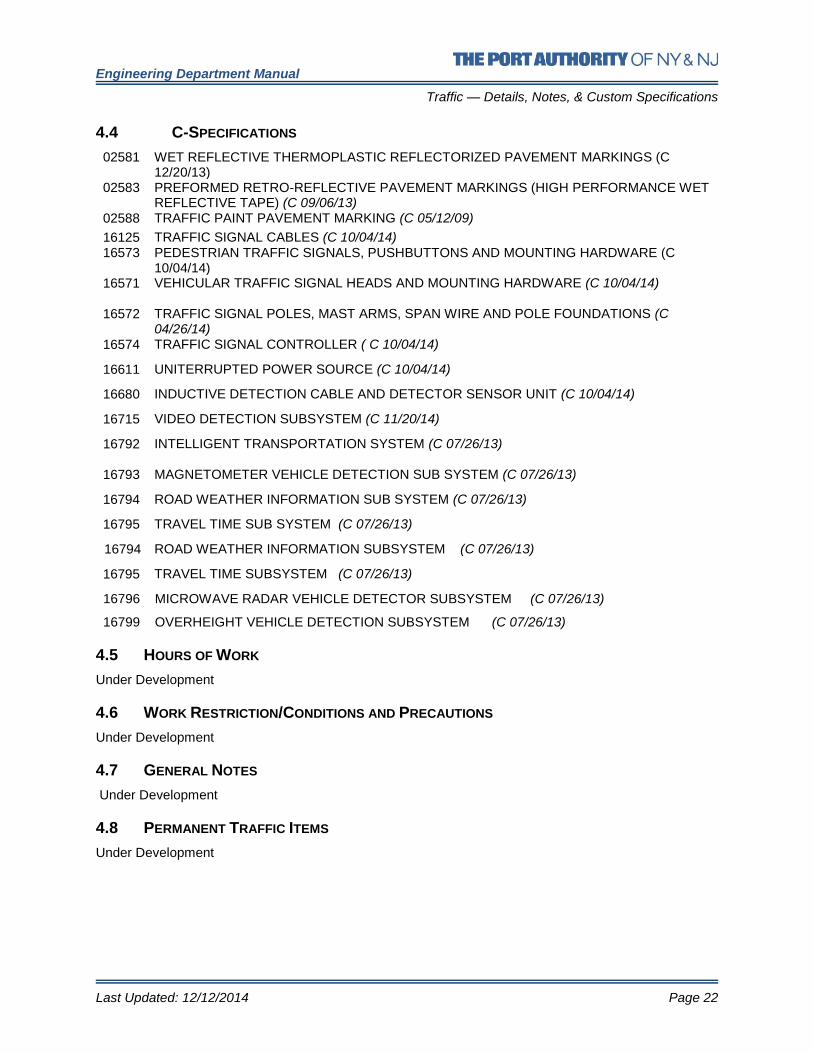
4.4 C-SPECIFICATIONS
02581 WET REFLECTIVE THERMOPLASTIC REFLECTORIZED PAVEMENT MARKINGS (C 12/20/13)
02583 PREFORMED RETRO-REFLECTIVE PAVEMENT MARKINGS (HIGH PERFORMANCE WET REFLECTIVE TAPE) (C 09/06/13)
02588 TRAFFIC PAINT PAVEMENT MARKING (C 05/12/09)
16125 16573
TRAFFIC SIGNAL CABLES (C 10/04/14) PEDESTRIAN TRAFFIC SIGNALS, PUSHBUTTONS AND MOUNTING HARDWARE (C 10/04/14)
16571 16572
VEHICULAR TRAFFIC SIGNAL HEADS AND MOUNTING HARDWARE (C 10/04/14) TRAFFIC SIGNAL POLES, MAST ARMS, SPAN WIRE AND POLE FOUNDATIONS (C 04/26/14)
16574 TRAFFIC SIGNAL CONTROLLER ( C 10/04/14)
16611 UNITERRUPTED POWER SOURCE (C 10/04/14)
16680 INDUCTIVE DETECTION CABLE AND DETECTOR SENSOR UNIT (C 10/04/14)
16715 VIDEO DETECTION SUBSYSTEM (C 11/20/14)
16792
INTELLIGENT TRANSPORTATION SYSTEM (C 07/26/13)
16793 MAGNETOMETER VEHICLE DETECTION SUB SYSTEM (C 07/26/13)
16794 ROAD WEATHER INFORMATION SUB SYSTEM (C 07/26/13)
16795 TRAVEL TIME SUB SYSTEM (C 07/26/13)
16794 ROAD WEATHER INFORMATION SUBSYSTEM (C 07/26/13)
16795 TRAVEL TIME SUBSYSTEM (C 07/26/13)
16796 MICROWAVE RADAR VEHICLE DETECTOR SUBSYSTEM (C 07/26/13)
16799 OVERHEIGHT VEHICLE DETECTION SUBSYSTEM (C 07/26/13)
4.5 HOURS OF WORK
Under Development
4.6 WORK RESTRICTION/CONDITIONS AND PRECAUTIONS
Under Development
4.7 GENERAL NOTES
Under Development
4.8 PERMANENT TRAFFIC ITEMS
Under Development

Engineering Department Manual
Traffic — Reference Materials
Last Updated: 12/12/2014 Page 23
5.0 REFERENCE MATERIALS
Standard Alphabet & Symbols for Pavement Markings
Transportation Research Board
5.1 OPERATING AND MAINTENANCE STANDARDS
5.1.1 PABT WORK AREA PROTECTION (O&M 73)
5.1.2 ROADWAY AREA PROTECTION (O&M 20)
5.1.3 TESTING ROADWAYS FOR SKID RESISTANCE (O&M 46)
5.1.4 TUNNEL ROADWAY AREA PROTECTION (O&M 37)
5.2 LANE CLOSURE GUIDELINES
5.2.1 AVIATION
5.2.2 TB&T
5.2.3 PORT COMMERCE
5.3 STANDARD HIGHWAY SIGNS
5.4 USDOT ITS STANDARDS
5.5 TRAFFIC ENGINEERING HANDBOOK
Under Development
5.6 FLAGGER’S HANDBOOK
Under Development
5.7 PORT AUTHORITY ROADWAY ACCESS MANAGEMENT GUIDELINES


![Red Wing Port Authority ]](https://static.fdocuments.in/doc/165x107/61aa87d8eee617376e4ff852/red-wing-port-authority-.jpg)