Design guidelines for semi-rigid steel-concrete composite ... · Design guidelines for semi-rigid...
11
Design guidelines for semi-rigid steel-concrete composite frames Senthilkumar R 1) and Satish Kumar S R 2) 1), 2) Department of Civil Engineering, IIT Madras, Chennai, India ABSTRACT Steel-concrete composite frames offer several advantages over pure steel or reinforced concrete constructions such as efficient sections in terms of strength, stiffness, economy and speed of construction. Semi-rigid connections can also be easily achieved by providing additional rebars in the slab to resist hogging moments at beam ends. However, design of these frames is a complex problem as the minimum connection stiffness and strength required to satisfy code limitations are not easy to determine. In this paper, design guidelines are proposed for semi-rigid steel concrete composite frames so as to satisfy strength, deflection and seismic drift limits. The seismic performance of a rigid and semi-rigid frame, designed to satisfy current codal provisions, are compared by carrying out non-linear static pushover analysis. The comparison indicates that, in low to moderate seismic areas, frames with semi-rigid connections can be designed to perform satisfactorily, thereby reducing the connection costs and the overall cost of the structure. 1. INTRODUCTION Composite construction is fast compared to cast-in-situ concrete construction. The increase in strength and stiffness due to composite action enables the use of larger beam spans under the same loading conditions. Semi-rigid connections provide economical options for designing such frames due to the reduced moment transfer from the beams to the columns. Frames with semi-rigid connections will also be more flexible compared to those employing rigid connections, thereby leading to a reduction in the seismic loads. In regions of low to moderate seismicity, semi-rigid connections may provide an economical and functional alternative to braced frames or frames with other lateral load resisting systems such as shear walls. Semi-rigid connections in composite frames, can be easily achieved at beam ends by providing additional rebars in the slab to resist hogging moments. Guidelines for the design of semi-rigid steel- concrete composite frames are limited in the literature. Design guidelines for semi-rigid (partially-restrained) composite connections of braced and unbraced frames have been developed by ASCE task committee (1998) based on a series of tests carried out by Leon et al (1987). These guidelines mainly focus on seat and web angle composite connections which does not have symmetric moment-rotation behaviour due to the 1) Research Scholar 2) Professor
Transcript of Design guidelines for semi-rigid steel-concrete composite ... · Design guidelines for semi-rigid...

Design guidelines for semi-rigid steel-concrete composite frames
Senthilkumar R1) and Satish Kumar S R2)
1), 2) Department of Civil Engineering, IIT Madras, Chennai, India
ABSTRACT Steel-concrete composite frames offer several advantages over pure steel or reinforced concrete constructions such as efficient sections in terms of strength, stiffness, economy and speed of construction. Semi-rigid connections can also be easily achieved by providing additional rebars in the slab to resist hogging moments at beam ends. However, design of these frames is a complex problem as the minimum connection stiffness and strength required to satisfy code limitations are not easy to determine. In this paper, design guidelines are proposed for semi-rigid steel concrete composite frames so as to satisfy strength, deflection and seismic drift limits. The seismic performance of a rigid and semi-rigid frame, designed to satisfy current codal provisions, are compared by carrying out non-linear static pushover analysis. The comparison indicates that, in low to moderate seismic areas, frames with semi-rigid connections can be designed to perform satisfactorily, thereby reducing the connection costs and the overall cost of the structure. 1. INTRODUCTION Composite construction is fast compared to cast-in-situ concrete construction. The increase in strength and stiffness due to composite action enables the use of larger beam spans under the same loading conditions. Semi-rigid connections provide economical options for designing such frames due to the reduced moment transfer from the beams to the columns. Frames with semi-rigid connections will also be more flexible compared to those employing rigid connections, thereby leading to a reduction in the seismic loads. In regions of low to moderate seismicity, semi-rigid connections may provide an economical and functional alternative to braced frames or frames with other lateral load resisting systems such as shear walls. Semi-rigid connections in composite frames, can be easily achieved at beam ends by providing additional rebars in the slab to resist hogging moments. Guidelines for the design of semi-rigid steel-concrete composite frames are limited in the literature. Design guidelines for semi-rigid (partially-restrained) composite connections of braced and unbraced frames have been developed by ASCE task committee (1998) based on a series of tests carried out by Leon et al (1987). These guidelines mainly focus on seat and web angle composite connections which does not have symmetric moment-rotation behaviour due to the
1)
Research Scholar 2)
Professor

opening up of the seat angle under sagging moments. Kumar and Smitha (2013) came up with flange-plate and stiffened flange plate semi-rigid connections and found that they had almost symmetrical behaviour in sagging and hogging. The energy dissipation capacity and ductility of these connections was also found to be adequate for use in seismic resistant frames. They also carried out parametric studies and gave equations to determine connection moment-rotation relationships and ductility (Smitha and Kumar 2013). Beams of semi-rigid frames were designed for full gravity loads without considering the effect of the connection stiffness (Sivakumaran 1988, Aksoylar 2012) or minimal effect of connection stiffness only was considered (ASCE 1998). However, codes do specify that effect of connection stiffness must be considered in both analysis and design (IS800: 2007). In this paper, design guidelines for semi-rigid steel concrete composite frames are proposed considering the effect of connection stiffness and the performance of rigid and semi-rigid steel concrete composite frames are compared. 2. DESIGN REQUIREMENTS FOR SEMI-RIGID FRAMES Connections are classified as semi-rigid based on their stiffness, strength and ductility capacities (Bjorhovde 1990, Eurocode 3, 2005). Ideally, the term „semi-rigid‟ should refer only to the stiffness and terms such as „partial-strength‟ and „limited-ductility‟ have been used to indicate the other aspects of the connection which are important only when loads exceed the design values as in the case of a severe earthquake. With reference to the stiffness, the ratio of connection stiffness to the flexural stiffness of the beam is used to determine semi-rigidity rather than the absolute stiffness of the connection. This ratio is known as the „joint factor‟ and is defined as follows:
(
)
(1)
Where,
= Secant Stiffness of connection corresponding to a specified rotation, E = Young‟s modulus I = Moment of inertia of the beam section and L = Span of the beam As per Eurocode classification, connection is considered semi-rigid when J lies between 0.5 to 25. 2.1 Design of Beams, Columns and Connections Preliminary size of beam section is calculated to satisfy the strength (Maximum moment) and serviceability (Maximum vertical deflection) limits. For a beam with semi-rigid connections of joint factor J at both ends, subjected to a uniformly distributed load of w per unit length, the support moment is given by:
(2)
The maximum span moment is given by:
(
) (3)

The maximum deflection can be calculated by moment area method by superposing the deflections corresponding to the bending moment diagrams for the load and support moments as follows:
(
) (
) (4)
Substituting Eq (2) in Eq (4)
(
) (5)
Where, (
)
Figure 1 .Variation of
with J
The design bending strength of the beam has to be greater than the maximum bending moments at mid-span and at support and the maximum deflection of the beam shall be within the limits specified by the code (L/300 in IS800:2007). Thus, the joint factor J plays an important role in both the required bending strength in span and support as well as in controlling the deflection. For a J value of zero, the beam behaves as simply supported and as J tends to infinity, it becomes a fixed-beam. The corresponding deflection also decreases exponentially from that of a simply supported beam to that of a fixed beam which is one-fifth of the former value as shown in figure 1. A minimum value of J can also be found which will just satisfy the two limit states. After designing the beams and connections, columns are designed for their corresponding axial loads and bending moments, considering second-order effects, arising out of all code-stipulated load combinations with appropriate load factors. Columns also need to be stronger than beams if capacity design approach is followed for seismic design. Also under design seismic loads, the roof and storey drift limits need to be satisfied (0.4% of storey height as per IS 1893:2002).The storey drift of a semi-rigid frame is the sum of drift contribution from the beams, columns and connections (ASCE task committee, 1998).
0
1
2
3
4
5
6
0 10 20 30
δS
R/δ
FF
J

Drift, ∆ =
Drift, (
) (6)
Where, V = Base shear, h = Storey height,
and
3. DESIGN GUIDELINES FOR SEMI-RIGID COMPOSITE FRAMES The three main issues to be considered in the design of semi-rigid composite frames are following: 1. Calculation of flexural stiffness of the composite beam 2.Prescribing connection stiffness for use in linear static analysis and 3. Evaluation of minimum connection stiffness and strength to satisfy the deflection and seismic drift limitations. The stiffness of composite beam is not uniform due to the variation of effective width of slab throughout the length of the beam. So, the average stiffness method is applied to calculate the equivalent moment of inertia (Ieq) as 60% of stiffness of the beam at mid span under sagging plus 40% of stiffness of the beam under hogging ASCE task committee (1998). The initial tangent rotational stiffness, Kt, of the connection non-linear moment rotation curve is often used to represent the equivalent linear stiffness of the connection in the analyses of semi-rigid frames. However, it produces an unacceptable overestimate of the connection stiffness and underestimates the frame deflection. The connection secant stiffness proposed by Bjorhovde (1984) which corresponds to a rotation of 0.01 rad underestimate the connection stiffness and results in higher drifts than actual. So, an intermediate value of secant stiffness corresponding to a rotation of 0.004 rad is used in this study so as to satisfy the drift limit of 0.4% of storey height as per IS 1893:2002. Thus, Connections are designed to attain maximum serviceability moment within 4mrad and maximum ultimate moment within 10 mrad.
Figure 2 .Variation of L/D with J
As described in the previous section, the minimum value of J needs to be found out to satisfy the strength as well as serviceability limit states under gravity loads. For composite beams, the depth of the steel section can be obtained as a function of the
23
26
29
32
35
38
41
0 5 10 15 20 25
L/D
Ratio
J

joint factor so as to satisfy the strength and serviceability criteria under gravity loads. Therefore for design, assuming a suitable value of J, the minimum depth of the steel beam required to satisfy the strength and serviceability criteria can be chosen from equation 7 which is derived in appendix. The variation of L/D with respect to the J is shown in figure 2.
(
) (
) (7)
Where, D = depth of steel beam section.
Beams and connections contribute significantly to the drift of semi-rigid frames. Since columns are designed for heavy axial load and second order moments it results in heavier sections than required sections to satisfy the drift limits. Column design is mostly governed by the strength and not serviceability limit state. But, beams and connections in semi-rigid frames are governed by the serviceability limit states, particularly the lateral storey drift. So, if the stiffness of beams and connections is uniform throughout the height of the frame, the inter-storey displacements of the frame will also be uniform. To get an idea of the percentage of the contribution of beams, columns and connections to the storey drift, a 4-storey and an 8-storey frame were designed. Bay width and storey height of the frames were taken as 8 m and 4 m, respectively. The frames were assumed to be spaced 4 m apart and supporting reinforced concrete slab of thickness 120 mm and masonry walls of thickness 230 mm, for calculating the dead and imposed loads, which are considered as per IS: 875:1987. Accordingly, the floor masses were obtained as 222 kN for all floors and 141 kN for roof. The frames are assumed to be located in seismic zone III on medium soil strata. A damping ratio of 5% was assumed for the steel-concrete composite frames. Base shear for the two frames were calculated by using equivalent static method given in IS1893:2000. Table1 and Table 2 show the storey drifts, calculated by using Eq (6), for the 4 and 8 storey frames, respectively. The summation of drifts due to beam and connection flexibility is nearly equal to 80% of the total drift. This is because, design of columns is governed by the strength criteria and design of beams and connections are governed by the serviceability criteria. So, to fix the beam and connection stiffness, the following condition should be satisfied for corresponding shear at each level.
∆beam + ∆conn ≤ 0.80 ∆ = 0.80* (0.004*h) (8)
Table1. Drifts of 4 storey semi-rigid composite frame
Storey ∆ Beam ∆ Conn ∆ Col Total * (∆Beam+∆Conn)%
1 4.97 5.07 2.3 12.34 81
2 4.78 4.88 2.2 11.86 81
3 4.00 5.00 2.83 11.83 76
4 3.42 4.38 1.61 9.41 83
*Permissible Limit = 0.004*h = 16mm
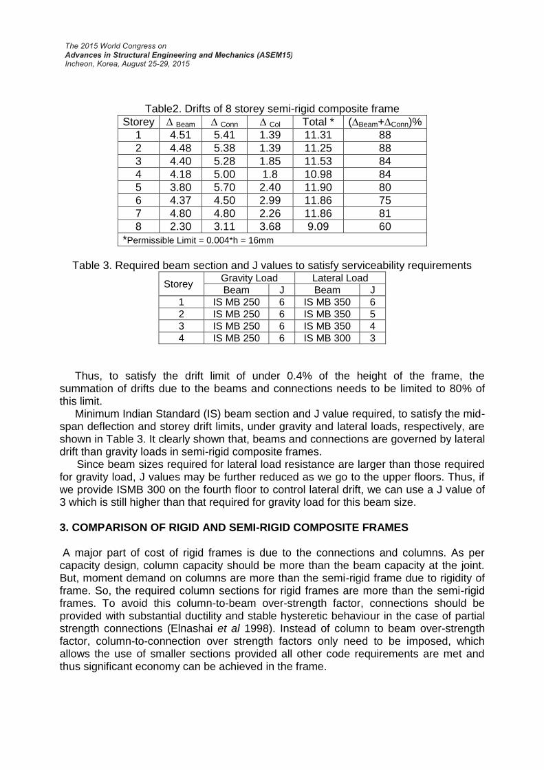
Table2. Drifts of 8 storey semi-rigid composite frame
Storey ∆ Beam ∆ Conn ∆ Col Total * (∆Beam+∆Conn)%
1 4.51 5.41 1.39 11.31 88
2 4.48 5.38 1.39 11.25 88
3 4.40 5.28 1.85 11.53 84
4 4.18 5.00 1.8 10.98 84
5 3.80 5.70 2.40 11.90 80
6 4.37 4.50 2.99 11.86 75
7 4.80 4.80 2.26 11.86 81
8 2.30 3.11 3.68 9.09 60
*Permissible Limit = 0.004*h = 16mm
Table 3. Required beam section and J values to satisfy serviceability requirements
Storey Gravity Load Lateral Load
Beam J Beam J
1 IS MB 250 6 IS MB 350 6
2 IS MB 250 6 IS MB 350 5
3 IS MB 250 6 IS MB 350 4
4 IS MB 250 6 IS MB 300 3
Thus, to satisfy the drift limit of under 0.4% of the height of the frame, the summation of drifts due to the beams and connections needs to be limited to 80% of this limit. Minimum Indian Standard (IS) beam section and J value required, to satisfy the mid-span deflection and storey drift limits, under gravity and lateral loads, respectively, are shown in Table 3. It clearly shown that, beams and connections are governed by lateral drift than gravity loads in semi-rigid composite frames. Since beam sizes required for lateral load resistance are larger than those required for gravity load, J values may be further reduced as we go to the upper floors. Thus, if we provide ISMB 300 on the fourth floor to control lateral drift, we can use a J value of 3 which is still higher than that required for gravity load for this beam size. 3. COMPARISON OF RIGID AND SEMI-RIGID COMPOSITE FRAMES A major part of cost of rigid frames is due to the connections and columns. As per capacity design, column capacity should be more than the beam capacity at the joint. But, moment demand on columns are more than the semi-rigid frame due to rigidity of frame. So, the required column sections for rigid frames are more than the semi-rigid frames. To avoid this column-to-beam over-strength factor, connections should be provided with substantial ductility and stable hysteretic behaviour in the case of partial strength connections (Elnashai et al 1998). Instead of column to beam over-strength factor, column-to-connection over strength factors only need to be imposed, which allows the use of smaller sections provided all other code requirements are met and thus significant economy can be achieved in the frame.

To compare the relative performance of semi-rigid and rigid composite frames, 6-storey frames of each type were designed with parameters identical to those described for the 4 and 8 storey frames earlier. . Both Rigid frame (6RF) and semi-rigid frame (6SRF) were designed as per force-based codal provisions. Fot the Semi-rigid frame, the fundamental time period and corresponding base shear was calculated from IS1893-2000 by the equivalent static method and distributed over the storeys in an inverted parabolic distribution. These frames are designed for design basis earthquake using reduction factor of 4. The parameters used to calculate base shear are shown in Table 2. Composite beams were designed as per IS 11384-1985, columns were designed as beam-columns accounting for second order effects for the governing load combinations as per IS 800-2007. Connection moment-rotation curve was modelled as linear rotational spring for linear static and eigenvalue analysis and nonlinear spring for Nonlinear Static Pushover analysis as described in modelling of frame elements.
Table 2: Equivalent static method
Time Period, T 0.92 sec
Zone factor, Z 0.16
Spectral Acceleration, Sa/g 1.48
Importance factor, I 1
Reduction factor, R 4
Base Shear, Vb 40 kN
Pushover analysis is frequently used in practice to study the ductility and
performance of the buildings under earthquake loading. ATC-40(1997) capacity spectrum method is used to find the performance point of the capacity curve under DBE (Design Basis Earthquake) and MCE (Maximum Considered Earthquake) response spectrums. Response spectrum of MCE is taken as twice that of DBE. Nonlinear Static Pushover analysis was carried out on rigid and semi-rigid steel concrete composite frames to evaluate their seismic performance using the software SAP2000 NL (2011). 3.1 Results and Discussions Base shear-displacement curves obtained for 6RF and 6SRF frames are shown in Figure 3. Rigid frame had slightly more initial stiffness and strength than semi-rigid frame. Connection and column sections used in rigid frames are stronger than those of semi-rigid frame as shown in Table 3. However, beam sections used in semi-rigid frame are higher than those of rigid frame to satisfy the lateral drift under serviceability condition. Overall, weight of the semi-rigid frame is 10% lesser than rigid frame due to the reduction in size of columns.
Global ductility of semi-rigid composite frame is much lower than the rigid composite frame as shown in Table 4. But, demands on connection and frame is less than the rigid composite frame and this ductility is enough to satisfy the performance limits for low seismic intensity as shown in Figure 5. Inter-storey drift limit of frames under MCE was taken as 3% of total height of the storey i.e. 120 mm, due to the limited ductility of semi-rigid composite frame. The Inter-storey drift limits of semi-rigid frame is less than this limit and has uniform drift. The reduction of drift at 5th floor level is due to the sudden reduction of beam and column sections.
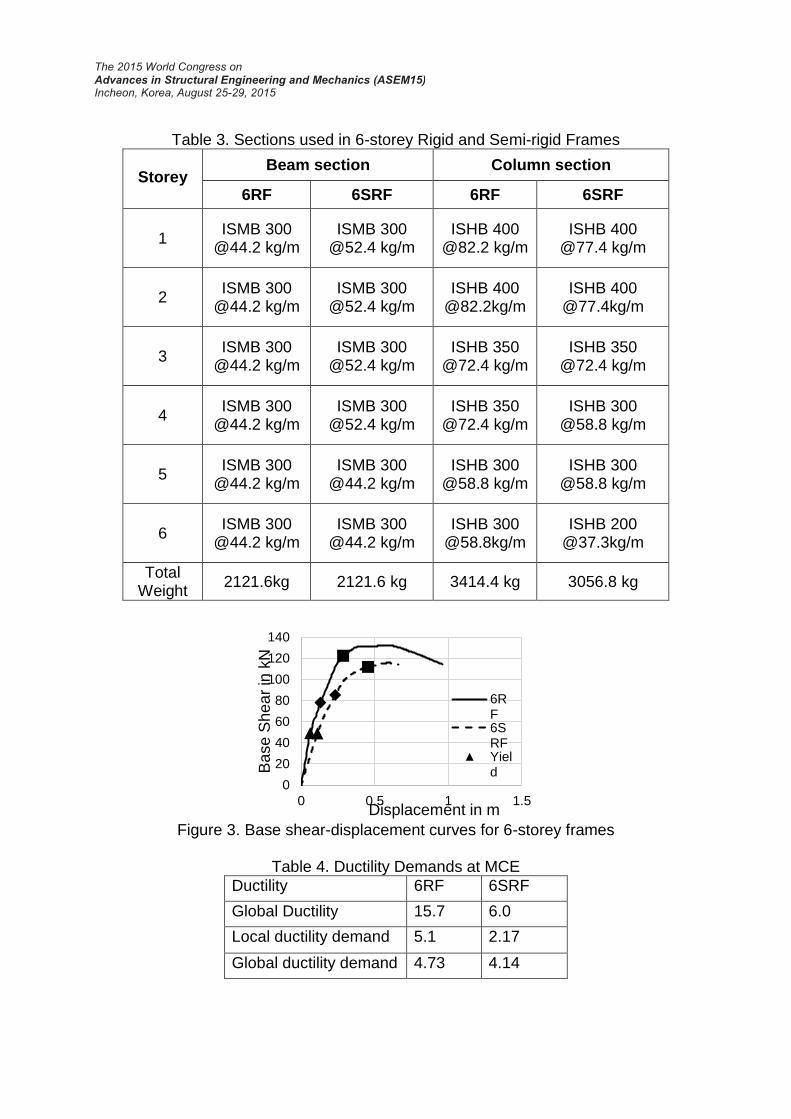
Table 3. Sections used in 6-storey Rigid and Semi-rigid Frames
Storey
Beam section Column section
6RF 6SRF 6RF 6SRF
1 ISMB 300
@44.2 kg/m ISMB 300
@52.4 kg/m ISHB 400
@82.2 kg/m ISHB 400
@77.4 kg/m
2 ISMB 300
@44.2 kg/m ISMB 300
@52.4 kg/m ISHB 400
@82.2kg/m ISHB 400
@77.4kg/m
3 ISMB 300
@44.2 kg/m ISMB 300
@52.4 kg/m ISHB 350
@72.4 kg/m ISHB 350
@72.4 kg/m
4 ISMB 300
@44.2 kg/m ISMB 300
@52.4 kg/m ISHB 350
@72.4 kg/m ISHB 300
@58.8 kg/m
5 ISMB 300
@44.2 kg/m ISMB 300
@44.2 kg/m ISHB 300
@58.8 kg/m ISHB 300
@58.8 kg/m
6 ISMB 300
@44.2 kg/m ISMB 300
@44.2 kg/m ISHB 300
@58.8kg/m ISHB 200
@37.3kg/m
Total Weight
2121.6kg 2121.6 kg 3414.4 kg 3056.8 kg
Figure 3. Base shear-displacement curves for 6-storey frames
Table 4. Ductility Demands at MCE
Ductility 6RF 6SRF
Global Ductility 15.7 6.0
Local ductility demand 5.1 2.17
Global ductility demand 4.73 4.14
0
20
40
60
80
100
120
140
0 0.5 1 1.5
Ba
se
Sh
ea
r in
kN
Displacement in m
6RF6SRFYield

Figure 4. IDI for lateral force corresponding Figure 5. IDI at MCE
0.4% drift 4. CONCLUSIONS
For a value of J, the variation of L/D is proposed to find the minimum steel beam section to satisfy strength and stiffness limits under gravity loads.
The minimum beam section and J value required to satisfy the deflection limit under gravity loads may not satisfy the lateral drift under seismic loads. So, the storey-drifts need to be checked for the prescribed limit in the codes.
The proposed design procedure can be used to achieve the desired performance in semi-rigid frames under design seismic loads and MCE.
Beam and column sections wise both rigid and semi-rigid frames are nearly same but the connection cost will be lesser in semi-rigid frames than rigid frames.
5. REFERENCES Aksoylar, N. D., Elnashai, A. S. and Mahmoud, H. (2012). “Seismic Performance of
Semi-rigid Moment Resisting Frames under Far and Near Field Records”. Journal of Structural Engineering ASCE, 138(2), 157-169.
ASCE Task Committee on Design Criteria for Composite Structures in Steel and Concrete (1998), “Design guide for partially restrained composite connections”, Journal of Structural Engineering ASCE, 124(10), 1099-1114
ATC-40 (1997). “Seismic Evaluation and Retrofit of Concrete Buildings”. Report No. ATC-40, Applied Technology Council, Redwood City, CA
Bjorhovde R (1984), “Effect of end restraint on column strength-practical application” Engineering Journal AISC, 20(1), 1-13
Bjorhovde, R. and Brozzetti, J. (1990). “Classification System for Beam-to-Column Connections”, Journal of Structural Engineering ASCE, 116(11), 3059-3076
Elnashai A. S., Elghazouli A. Y. and Denesh F. A. (1998). “Response of Semi-Rigid Steel Frames to Cyclic and Earthquake Loads”, Journal of Structural Engineering ASCE, 124(8), 857-867
1
2
3
4
5
6
0.1 0.2 0.3 0.4 0.5 0.6
Sto
rey
IDI in %
6SRF6RF
1
2
3
4
5
6
0.0 1.0 2.0 3.0 4.0 5.0
Sto
rey
IDI in %
6SRF6RF

Kumar, S. R. S. and Smitha, M. S. (2013), “Steel-Concrete Composite Flange Plate Connections: Cyclic performance and tests”, Journal of Constructional Steel research, Elsevier, 82, 216-222.
IS 11384:1985, “Code of practice for composite construction in steel and concrete”, Bureau of Indian Standards, New Delhi, India.
IS 875:1987, “Code of practice for Design loads (other than Earthquake) for Buildings and Structures”, Bureau of Indian Standards, New Delhi, India.
IS 1893:2002, “Criteria for Earthquake Resistant Design of Structures- General Provisions and Buildings”, Bureau of Indian Standards, New Delhi, India.
IS 800:2007, “Code of practice for General Construction in Steel”, Bureau of Indian Standards, New Delhi, India.
Leon R. T., Ammerman D. J., Lin J. and McCauley R. D. (1987). “Semi-rigid Composite steel frames”, Engineering Journal AISC, 147-155.
prEN 1993-1. Eurocode 3: “Design of steel structures. Part 1: General rules for buildings”, CEN; 2005
Sap2000 User‟s Manual (2011), Computer and Structures, inc., Berkeley. Sivakumaran, K. S. (1988), “Seismic response of multi-storey steel buildings with
flexible connections”, Engineering Structures, Elsevier, 10, 239-248. Smitha, M. S. and Kumar, S. R. S. (2013), “Semi-rigid Composite Flange Plate
Connections-finite element modelling and parametric studies”, Journal of Constructional Steel research , Elsevier, 82, 164-176.
APPENDIX Consider a beam with semi-rigid connections at its ends, subjected to a UDL at service of w per unit length. Deflection of semi-rigid beam = (Deflection of simply supported beam ( ) –
(Deflection due to fixed end moment „M‟ ( )
(
) (
) (A1)
Fixed end moment,
(A2)
Substitute Eq (2) in Eq (1)
(
)
(
) (
) (A3)
Deflection of fixed -fixed beam is given by,
M
K K
w M
(
) (A4)
Dividing Eq (3) by Eq (4)
(A5)
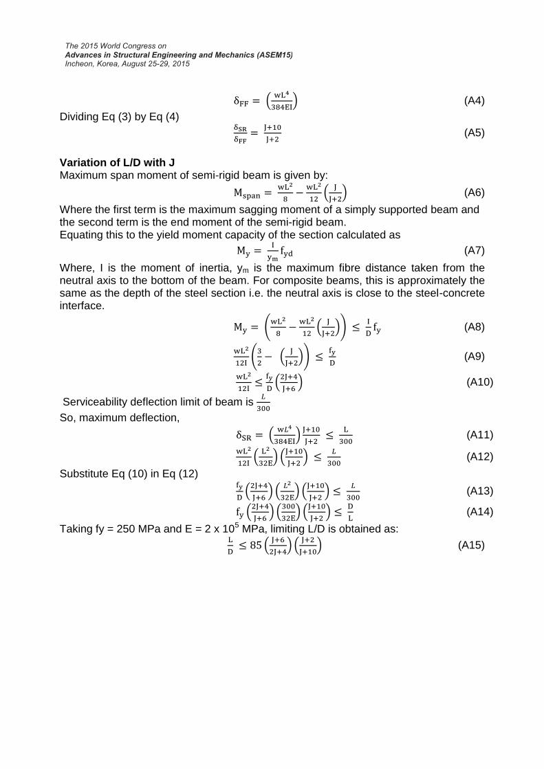
Variation of L/D with J Maximum span moment of semi-rigid beam is given by:
(
) (A6)
Where the first term is the maximum sagging moment of a simply supported beam and the second term is the end moment of the semi-rigid beam. Equating this to the yield moment capacity of the section calculated as
(A7)
Where, I is the moment of inertia, ym is the maximum fibre distance taken from the neutral axis to the bottom of the beam. For composite beams, this is approximately the same as the depth of the steel section i.e. the neutral axis is close to the steel-concrete interface.
(
(
))
(A8)
(
(
))
(A9)
(
) (A10)
Serviceability deflection limit of beam is
So, maximum deflection,
(
)
(A11)
(
) (
)
(A12)
Substitute Eq (10) in Eq (12)
(
) (
) (
)
(A13)
(
) (
) (
)
(A14)
Taking fy = 250 MPa and E = 2 x 10⁵ MPa, limiting L/D is obtained as:
(
) (
) (A15)