Design formulae for a concave convex arc line gear … · Design formulae for a concave convex arc...
10
Mech. Sci., 7, 209–218, 2016 www.mech-sci.net/7/209/2016/ doi:10.5194/ms-7-209-2016 © Author(s) 2016. CC Attribution 3.0 License. Design formulae for a concave convex arc line gear mechanism Yangzhi Chen and Li Yao School of Mechanical and Automotive Engineering, South China University of Technology, Guangzhou, 510640, People’s Republic of China Correspondence to: Yangzhi Chen ([email protected]) Received: 11 July 2016 – Revised: 17 October 2016 – Accepted: 30 October 2016 – Published: 11 November 2016 Abstract. Line gear is a newly developed gear mechanism with point contact meshing according to space curve meshing theory. This paper proposes a new form of line gear with a couple of concave convex arc tooth profiles. It has four characteristics. First, contact curve of the driving line gear is a cylindrical spiral curve. Second, two axes of a pair of line gears are located in the same plane with an arbitrary angle. Third, at the mesh point, normal tooth profiles of a line gear pair are a couple of inscribed circles. Namely, they form a couple of concave convex tooth profiles. Fourth, the tooth profile of a driving line gear is a convex, that of a driven line gear is a concave, and they are interchangeable. If only consider that the arcs of teeth at meshing point are tangent, the actual tooth surfaces may interfere outside of the meshing point. In this paper, the geometric condition of the tooth surface for a concave convex arc line gear mechanism is derived, and the optimal formulae of the tooth profile parameters are derived on basis of interference proof conditions. Finally, the 3-D modeling and kinematic simulation of line gear pairs show that the proposed line gear pairs can perform transmission normally. The proposed method will extend the application of line gear in the conventional power drive. 1 Introduction The concave convex arc line gear (Chen and Yao, 2015) is the line gear with arc tooth profile. The arc gear has advan- tages in large loading capacity. For instance, Sun et al. (2016) investigated the contact strength of the circular-arc-tooth- trace cylindrical gear (C-gear). The results reveal that the C-gear is superior to spur gear and helical gear in the con- tact strength. The curvilinear tooth gear proposed by Zhang et al. (2016) is superior to spur gear in contact and bending stress. The Double Circular-Arc Helical Gear developed by Wang (2012) can be used for heavily-loaded planetary gear reducer. The circular-arc gear designed by Zhou et al. (2016) can be used for a high-pressure and high-speed gear pump in the aerospace application. Because of the advantages of arc tooth, scholars have used the arc tooth in many different types of gear transmission. They are hyperboloidal-type nor- mal circular-arc gears (Chen et al., 2016), helical gear with triple circular-arc teeth (Xie and Yang, 2014), quadruple-arc Profile Bevel Gears (Ren, 2014), a new kind of gear trans- mission with circular arc tooth profiles (Chen et al., 2014), etc. All of these belong to cylindrical gear. Arc tooth are also used in bevel gears (Dong and Wang, 2014; Zhang et al., 2011, 2012) and worm (Zhao and Zhang, 2011). The concave convex arc line gear is a new form of line gear. The early line gear is also called the space curve mesh- ing wheel. It contains a driving wheel, a driven wheel, driving tines and driven tines (Chen et al., 2013b). A cantilever struc- ture is formed by the combination of the tines and the wheel body. Compared with the previous proposed line gear, the concave convex arc line gear has the advantages of arc gear. It is better than the early line gears in loading capacity, bears much lower contact and bending stress. It can be applied to conventional power transmission with larger power. It can be processed by the metal cutting machine tool. Compared with other arc gear, it has the advantages of line gear. It has a large transmission ratio and compact structure. The gear shafts of the gear pair can be crossed at any angle. It means that the conventional gear pair must be a driven wheel corresponding to a driving wheel. The concave convex arc line gear pair can be designed as a driving gear and a corresponding plurality Published by Copernicus Publications.
-
Upload
nguyennguyet -
Category
Documents
-
view
228 -
download
1
Transcript of Design formulae for a concave convex arc line gear … · Design formulae for a concave convex arc...

Mech. Sci., 7, 209–218, 2016www.mech-sci.net/7/209/2016/doi:10.5194/ms-7-209-2016© Author(s) 2016. CC Attribution 3.0 License.
Design formulae for a concave convex arc line gearmechanism
Yangzhi Chen and Li YaoSchool of Mechanical and Automotive Engineering, South China University of Technology,
Guangzhou, 510640, People’s Republic of China
Correspondence to: Yangzhi Chen ([email protected])
Received: 11 July 2016 – Revised: 17 October 2016 – Accepted: 30 October 2016 – Published: 11 November 2016
Abstract. Line gear is a newly developed gear mechanism with point contact meshing according to space curvemeshing theory. This paper proposes a new form of line gear with a couple of concave convex arc tooth profiles.It has four characteristics. First, contact curve of the driving line gear is a cylindrical spiral curve. Second, twoaxes of a pair of line gears are located in the same plane with an arbitrary angle. Third, at the mesh point, normaltooth profiles of a line gear pair are a couple of inscribed circles. Namely, they form a couple of concave convextooth profiles. Fourth, the tooth profile of a driving line gear is a convex, that of a driven line gear is a concave,and they are interchangeable. If only consider that the arcs of teeth at meshing point are tangent, the actual toothsurfaces may interfere outside of the meshing point. In this paper, the geometric condition of the tooth surface fora concave convex arc line gear mechanism is derived, and the optimal formulae of the tooth profile parametersare derived on basis of interference proof conditions. Finally, the 3-D modeling and kinematic simulation of linegear pairs show that the proposed line gear pairs can perform transmission normally. The proposed method willextend the application of line gear in the conventional power drive.
1 Introduction
The concave convex arc line gear (Chen and Yao, 2015) isthe line gear with arc tooth profile. The arc gear has advan-tages in large loading capacity. For instance, Sun et al. (2016)investigated the contact strength of the circular-arc-tooth-trace cylindrical gear (C-gear). The results reveal that theC-gear is superior to spur gear and helical gear in the con-tact strength. The curvilinear tooth gear proposed by Zhanget al. (2016) is superior to spur gear in contact and bendingstress. The Double Circular-Arc Helical Gear developed byWang (2012) can be used for heavily-loaded planetary gearreducer. The circular-arc gear designed by Zhou et al. (2016)can be used for a high-pressure and high-speed gear pumpin the aerospace application. Because of the advantages ofarc tooth, scholars have used the arc tooth in many differenttypes of gear transmission. They are hyperboloidal-type nor-mal circular-arc gears (Chen et al., 2016), helical gear withtriple circular-arc teeth (Xie and Yang, 2014), quadruple-arcProfile Bevel Gears (Ren, 2014), a new kind of gear trans-mission with circular arc tooth profiles (Chen et al., 2014),
etc. All of these belong to cylindrical gear. Arc tooth arealso used in bevel gears (Dong and Wang, 2014; Zhang etal., 2011, 2012) and worm (Zhao and Zhang, 2011).
The concave convex arc line gear is a new form of linegear. The early line gear is also called the space curve mesh-ing wheel. It contains a driving wheel, a driven wheel, drivingtines and driven tines (Chen et al., 2013b). A cantilever struc-ture is formed by the combination of the tines and the wheelbody. Compared with the previous proposed line gear, theconcave convex arc line gear has the advantages of arc gear.It is better than the early line gears in loading capacity, bearsmuch lower contact and bending stress. It can be applied toconventional power transmission with larger power. It can beprocessed by the metal cutting machine tool. Compared withother arc gear, it has the advantages of line gear. It has a largetransmission ratio and compact structure. The gear shafts ofthe gear pair can be crossed at any angle. It means that theconventional gear pair must be a driven wheel correspondingto a driving wheel. The concave convex arc line gear pair canbe designed as a driving gear and a corresponding plurality
Published by Copernicus Publications.

210 Y. Chen and L. Yao: Design formulae for a concave convex arc line gear mechanism
Figure 1. A pair of concave convex arc line gears at the meshing point.
of driven gears. The minimum tooth number of line gear canreach 1 (Chen, 2014). But it can bear lower contact stressthan other conventional forms of arc gear above due to pointcontact meshing.
The main objective of the work is to improve the origi-nal form of line teeth profile, to be capable of applying inconventional power transmission. If the line gear is only thecombination of the characteristics of the space curve mesh-ing wheel and the characteristics of the arc gear, it cannot beprocessed by the metal cutting machine tool. It also showsthe importance of the gear profile and the parameter quan-tization. Moreover, the tooth profile parameters and gear pa-rameters are quantified to provide the basis for the analysis ofgear strength. A new design method of the concave convexarc line gear is presented in this paper, aiming to solve theproblem of tooth surface geometry interference and the op-timization of the tooth profile parameters. In order to verifythe feasibility of the parametric design and tooth profile pa-rameters optimization of concave convex arc line gears, thispaper presents the specific example and the 3-D modelingand kinematic simulation of the line gear.
2 Basic design
A pair of concave convex arc line gears is comprised a driv-ing line gear and a driven line gear. As shown in Fig. 1a, theaxes of the driving line gear and the driven line gear are arbi-trary angle intersected axes in one plane. The angle is θ . Thecontact curve of the driving line gear is a spatial cylinder spi-ral curve, which forms a pair of conjugated space curves withthe contact curve of the driven line gear. The contact curvesof the driving line gear and the driven line gear are located ino1− x1 y1 z1 and o2− x2 y2 z2 respectively. The distance be-tween o1 and o2 is the center distance of the driving line gear
and the driven line gear. As shown in Fig. 1b, the tooth pro-files of line gears are a pair of inscribed circles at the meshpoint oM. And the point oM is also the tangent point. Thepoint oM and the center points of the circles are located onone straight line, which has an angle of φ with xM. And−xMis the secondary normal vector of contact curve of the drivingline gear at the mesh point oM (Chen and Yao, 2015).
The contact curve of the driving line gear, namely a drivingcontact curve, is set as a spatial cylinder spiral curve. And theparametric equation in o1− x1 y1 z1 is as Eq. (1) (Ding et al.,2012).x
(1)M =mcos ty
(1)M =msin tz
(1)M = nπ + nt
(1)
where m is the helix radius of the cylindrical spiral curve;n is the pitch parameter of the cylindrical spiral curve, denot-ing the pitch as p, n= p
2π ; t is a parameter variable, t ∈ [ts,te]. The value range of t determines the length of the con-tact curve. ts and te are the starting and ending values for themeshing point, respectively. ts=−π − 1t
2 , te=−π + 1t2 ,
1t = te− ts. The value of 1t satisfies the condition of con-tact ratio (Chen et al., 2013a): ε= 1t N1
2π ≥ 1. N1 and N2 arethe tooth numbers of the driving line gear and the driven linegear respectively. The value of ε needs to be preferred. Andthe value of 1t can be deduced. Then the value of ts and tecan be determined. Therefore, ε, N1, m and n are the keyfactors of the contact curve of the driving line gear.
The contact curve of the driven line gear is conjugated withthe driving contact curve, and the equation in o2− x2 y2 z2 isas Eq. (2) (Ding et al., 2012).
Mech. Sci., 7, 209–218, 2016 www.mech-sci.net/7/209/2016/

Y. Chen and L. Yao: Design formulae for a concave convex arc line gear mechanism 211
x
(2)M = [(m− a)cosθ − (nπ + nt − b) sinθ ]cos
t +π
i12
y(2)M =−[(m− a)cosθ − (nπ + nt − b) sinθ ]sin
t +π
i12z
(2)M =−(m− a) sinθ − (nπ + nt − b)cosθ
(2)
where i12 is the transmission ratio, i12=N2N1
. As shown inFig. 1, a and b are the components of the center distancefrom the axis x1 and axis z1 respectively. The position pa-rameters for the concave convex arc line gear mechanism canbe derived from Eq. (3) or (4) (Ding et al., 2014).{a = (1+ i12 cosθ )mb = (m− a) tanθ (3){a =m
b = i12m(4)
where θ is the included angle between the angular velocityvectors of the driving and driven line gear, θ ∈ [0, π ]. Whenθ 6= π
2 , the values of a and b are derived from Eq. (3). Whenθ = π
2 , the values of a and b can be obtained by Eq. (4).Therefore, i12, θ , a, b, m and n are the key factors of thecontact curve of the driven line gear.
2.1 Parametric design formulae for the driving line gear
A driving line gear is formed by driving line gear teeth radialattachment to a cylindrical wheel body. The gear teeth can beconvex or concave, and the gear with convex teeth is taken asan example here. As shown in Fig. 2, a convex tooth of adriving line gear is formed by the motion of a convex normalprofile along a driving contact curve and two tooth thicknessauxiliary curves.
The two tooth thickness auxiliary curves have two func-tions. Firstly, they lead the movement of the auxiliary lineof the gear tooth profile. Secondly, they provide the nor-mal tooth thickness of the gear teeth. The auxiliary curvesof tooth thickness comprise a first auxiliary curve and a sec-ond auxiliary curve. A first auxiliary curve 2 is arranged be-tween a contact curve 1 and a second auxiliary curve 3, andits equation in o1− x1 y1 z1 is as Eq. (5).x
(1)M11=mcos t −
c1nsin t√n2+m2
y(1)M11=msin t +
c1ncos t√n2+m2
z(1)M11= nπ + nt −
c1m√n2+m2
(5)
The equation of a second auxiliary curve 3 in o1− x1 y1 z1 isas Eq. (6).x
(1)M12=mcos t −
2c1nsin t√n2+m2
y(1)M12=msin t +
2c1ncos t√n2+m2
z(1)M12= nπ + nt −
2c1m√n2+m2
(6)
Figure 2. Schematic diagram of the driving line gear.
where, 2c1 is the normal tooth thickness of the driving linegear.
The driving line gear is designed by determining the fol-lowing parameters. Parameters of a driving line gear includedriving contact curve parameters, tooth profile parametersand wheel body parameters. Driving contact curve param-eters cover m and n. Tooth profile parameters of the drivingline gear are shown in Fig. 3. The tooth profile is composedof two sections of arcs and a section of straight line. Thetwo sections of arcs are symmetrical to a first auxiliary curveof tooth thickness in the plane of the normal tooth profile,and the radius of the arc is ρ1. At the mesh point, the anglebetween a straight line and −γ is φ. And the straight lineis a connection between the mesh point and arc center. Andγ is the secondary normal vector of contact curve of the driv-ing line gear. The straight line of the driving line gear toothprofile is parallel to −γ . The distance between them is ha1.ha1 and hf 1 are the driving line gear addendum and deden-dum respectively. As shown in Fig. 2, wheel body parametersinclude diameter df 1 and lengthL. The complete driving linegear model can be established by the cylindrical wheel bodyand the line gear convex teeth, in which the height of thetooth is limited by the driving contact curve and ha1. Andhf 1 is not required to be calculated. In the engagement of acouple conjugated space curves, the contact ratio affects thecurve length, indirectly determines the length of a driving
www.mech-sci.net/7/209/2016/ Mech. Sci., 7, 209–218, 2016
212 Y. Chen and L. Yao: Design formulae for a concave convex arc line gear mechanism
Figure 3. Schematic diagram of the normal tooth profile of the driv-ing line gear.
line gear. Therefore, the value of L is related to the contactratio. And it depends on ts and te.
2.2 Parametric design formulae of the driven line gear
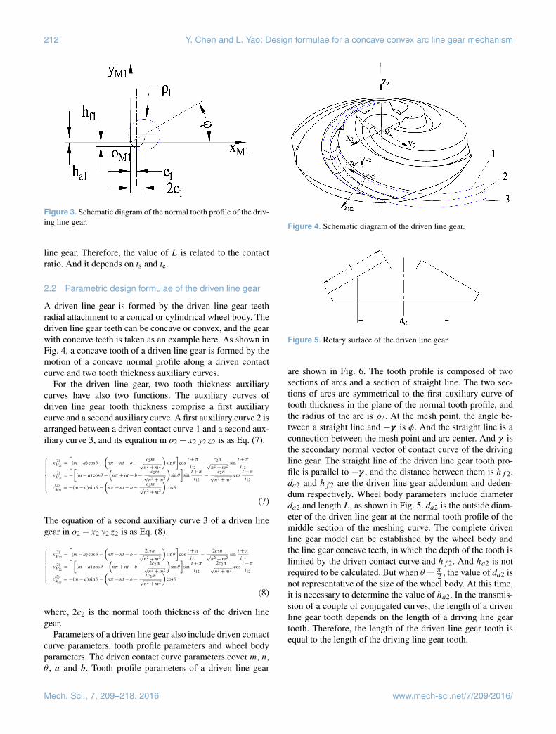
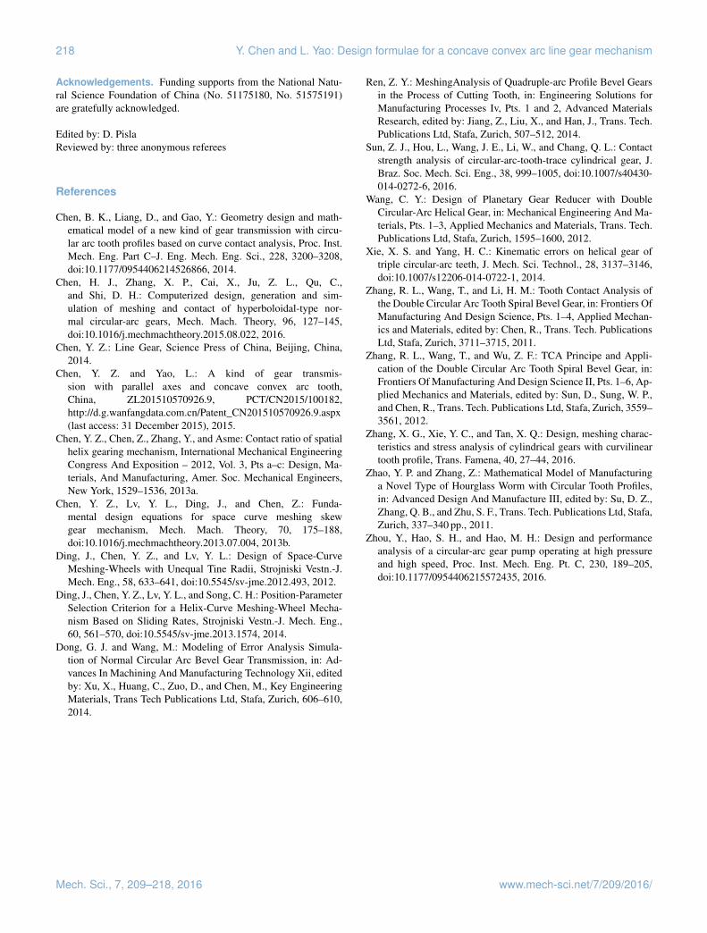
A driven line gear is formed by the driven line gear teethradial attachment to a conical or cylindrical wheel body. Thedriven line gear teeth can be concave or convex, and the gearwith concave teeth is taken as an example here. As shown inFig. 4, a concave tooth of a driven line gear is formed by themotion of a concave normal profile along a driven contactcurve and two tooth thickness auxiliary curves.
For the driven line gear, two tooth thickness auxiliarycurves have also two functions. The auxiliary curves ofdriven line gear tooth thickness comprise a first auxiliarycurve and a second auxiliary curve. A first auxiliary curve 2 isarranged between a driven contact curve 1 and a second aux-iliary curve 3, and its equation in o2− x2 y2 z2 is as Eq. (7).
x
(2)M21=
[(m− a)cosθ −
(nπ + nt − b−
c2m√n2 +m2
)sinθ
]cos
t +π
i12−
c2n√n2 +m2
sint +π
i12
y(2)M21=−
[(m− a)cosθ −
(nπ + nt − b−
c2m√n2 +m2
)sinθ
]sin
t +π
i12−
c2n√n2 +m2
cost +π
i12
z(2)M21=−(m− a) sinθ −
(nπ + nt − b−
c2m√n2 +m2
)cosθ
(7)
The equation of a second auxiliary curve 3 of a driven linegear in o2− x2 y2 z2 is as Eq. (8).
x
(2)M22=
[(m− a)cosθ −
(nπ + nt − b−
2c2m√n2 +m2
)sinθ
]cos
t +π
i12−
2c2n√n2 +m2
sint +π
i12
y(2)M22=−
[(m− a)cosθ −
(nπ + nt − b−
2c2m√n2 +m2
)sinθ
]sin
t +π
i12−
2c2n√n2 +m2
cost +π
i12
z(2)M22=−(m− a) sinθ −
(nπ + nt − b−
2c2m√n2 +m2
)cosθ
(8)
where, 2c2 is the normal tooth thickness of the driven linegear.
Parameters of a driven line gear also include driven contactcurve parameters, tooth profile parameters and wheel bodyparameters. The driven contact curve parameters cover m, n,θ , a and b. Tooth profile parameters of a driven line gear
Figure 4. Schematic diagram of the driven line gear.
Figure 5. Rotary surface of the driven line gear.
are shown in Fig. 6. The tooth profile is composed of twosections of arcs and a section of straight line. The two sec-tions of arcs are symmetrical to the first auxiliary curve oftooth thickness in the plane of the normal tooth profile, andthe radius of the arc is ρ2. At the mesh point, the angle be-tween a straight line and −γ is φ. And the straight line is aconnection between the mesh point and arc center. And γ isthe secondary normal vector of contact curve of the drivingline gear. The straight line of the driven line gear tooth pro-file is parallel to −γ , and the distance between them is hf 2.da2 and hf 2 are the driven line gear addendum and deden-dum respectively. Wheel body parameters include diameterda2 and length L, as shown in Fig. 5. da2 is the outside diam-eter of the driven line gear at the normal tooth profile of themiddle section of the meshing curve. The complete drivenline gear model can be established by the wheel body andthe line gear concave teeth, in which the depth of the tooth islimited by the driven contact curve and hf 2. And ha2 is notrequired to be calculated. But when θ = π
2 , the value of da2 isnot representative of the size of the wheel body. At this time,it is necessary to determine the value of ha2. In the transmis-sion of a couple of conjugated curves, the length of a drivenline gear tooth depends on the length of a driving line geartooth. Therefore, the length of the driven line gear tooth isequal to the length of the driving line gear tooth.
Mech. Sci., 7, 209–218, 2016 www.mech-sci.net/7/209/2016/

Y. Chen and L. Yao: Design formulae for a concave convex arc line gear mechanism 213
Figure 6. Schematic diagram of the normal tooth profile of thedriven line gear.
3 The optimal formulae of the tooth profileparameters of a concave convex arc line gearmechanism
3.1 Interference proof condition
As shown in Fig. 7a, if only consider that the tooth pro-file arcs are tangent at meshing point, the actual surfaces ofthe driving line gear tooth and driven line gear tooth mayinterfere with each other outside of meshing point, result-ing in abnormal engagement. The tooth surface can be con-sidered as a set of tooth profiles on normal plane of eachpoint at the contact curve of the driving line gear. The rela-tionship between the driving line gear tooth profile and thedriven line gear tooth profile on the normal plane of meshingpoint is shown in Fig. 7b–d. Coordinate system oE− xE yE zEis established, which is obtained by the coordinate systemoM1− xM1 yM1 zM1 moving a distance parallel to ρ1 on theplane xM1 oM1 yM1. The origin of system oE− xE yE zE is lo-cated at the center of arc of the driving line gear tooth profile,as shown in Fig. 7b and c. Therefore, the Interference proofcondition of teeth surfaces is that the distance between oEand any point of driven line gear tooth profile arc is not lessthan ρ1.
3.2 Transformation of the coordinate systems
The origin of the coordinate system oM1− xM1 yM1 zM1 islocated on the contact curve of the driving line gear, and thedirections of each coordinate axis are −γ , β and α. Where,α, β and γ are the tangent vector, normal vector and sec-ondly normal vector of the contact curve of the driving linegear respectively. The equation of the driven line gear toothsurface is obtained through the coordinate transformation ofoE− xE yE zE and o2− x2 y2 z2, which is as Eq. (9).X
Y
Z
1
=Me2
x
y
z
1
(9)
The equation of Me2 is as Eq. (10).
Me2 =
sinλ1 sinδ1· (cosφ1 cosφ2 cosθ+ sinφ1 sinφ2 )+ cosδ1 (sinφ1 cosφ2 cosθ− cosφ1 sinφ2 )+ sinδ1 cosλ1 cosφ2 sinθ
− sinλ1 sinδ1· (cosφ1 sinφ2 cosθ− sinφ1 cosφ2 )− cosδ1 (sinφ1 sinφ2 cosθ+ cosφ1 cosφ2 )− sinδ1 cosλ1 sinφ2 sinθ
− sinλ1 sinδ1· cosφ1 sinθ− cosδ1 sinφ1 sinθ− sinδ1 cosλ1 cosθ
a sinλ1· sinδ1 cosφ1+ a cosδ1 sinφ1+ b sinδ1 cosλ1− x1 − ρ1 cosφ
− sinλ1 cosδ1· (cosφ1 cosφ2 cosθ+ sinφ1 sinφ2 )+ sinδ1 (sinφ1 cosφ2 cosθ− cosφ1 sinφ2 )− cosδ1 cosλ1 cosφ2 sinθ
sinλ1 cosδ1· (cosφ1 sinφ2 cosθ− sinφ1 cosφ2 )− sinδ1 (sinφ1 sinφ2 cosθ+ cosφ1 cosφ2 )+ cosδ1 cosλ1 sinφ2 sinθ
sinλ1 cosδ1· cosφ1 sinθ− sinδ1 sinφ1 sinθ+ cosδ1 cosλ1 cosθ
− a sinλ1· cosδ1 cosφ1+ a sinδ1 sinφ1− bcosδ1 cosλ1− y1 − ρ1 sinφ
(− cosλ1 (cosφ1 cosφ2 cosθ+ sinφ1 sinφ2 )+ sinλ1 cosφ2 sinθ
) (cosλ1 (cosφ1 sinφ2 cosθ− sinφ1 cosφ2 )− sinλ1 sinφ2 sinθ
) (cosλ1 cosφ1 sinθ− sinλ1 cosθ
) (− a cosλ1 cosφ1+ b sinλ1 − z1
)0 0 1
(10)
where φ1= t +π ; φ2=t+πi12
; λ1 is the helix angle of contactcurve of the driving line gear, λ1= arctan n
m; δ1 is the in-
cluded angle of β and axis x1, δ1= arccos( (x1,y1,0)·(1,0,0)|(x1,y1,0)||(1,0,0)| );
x1, y1 and z1 are the values of the coordinate origin oM1 ino1− x1 y1 z1.
3.3 The equation of the main tooth surface of the drivenline gear
The tooth surface of the driven line gear is formed by a circu-lar arc with a radius of ρ2 along the three space curves. At theinitial position, the center of the circle arc is at point (xc, yc,zc), which is obtained by coordinate transformation of (x2s ,y2s , z2s), the equation is as Eq. (11).
xc = x2s + ρ2 sinφ = [(m− a)cosθ − (nπ + nts − b) sinθ]costs +πi12
yc = y2s − ρ2 cosφ sinλ2 =− [(m− a)cosθ − (nπ + nts − b) sinθ ] sints +πi12
zc = z2s − ρ2 cosφ cosλ2 =−(m− a) sinθ − (nπ + nts − b)cosθ
(11)
where, λ2 is the helix angle of the contact curve of drivenline gear.
Taking u as a parameter variable, the equation of the arc isas Eq. (12).x0 = xc+ ρ2 cosuy0 = yc− ρ2 sinusinλ2z0 = zc− ρ2 sinucosλ2
(12)
The equation of the driven line gear tooth surface ino2− x2 y2 z2 is as Eq. (13).
x = x0
(1+
ni12 (φ2 −π ) sinθ(m− a)cosθ − (nπ + nts − b) sinθ
)cos(φ2 −π )− y0
(1+
ni12 (φ2 −π ) sinθ(m− a)cosθ − (nπ + nts − b) sinθ
)sin(φ2 −π )
y = x0
(1+
ni12 (φ2 −π ) sinθ(m− a)cosθ − (nπ + nts − b) sinθ
)sin(φ2 −π )+ y0
(1+
ni12 (φ2 −π ) sinθ(m− a)cosθ − (nπ + nts − b) sinθ
)cos(φ2 −π )
z= z0 − (m− a) sinθ − (ni12φ2 − b)cosθ
(13)
Substituting Eq. (13) into Eq. (9), the equation of driven linegear tooth surface in oE− xE yE zE is obtained.
3.4 Parameter optimization
From Fig. 7c, d and Eq. (9), the interference proof conditionof tooth surfaces between a driving line gear and a driven linegear is described as Eqs. (14) and (15).
www.mech-sci.net/7/209/2016/ Mech. Sci., 7, 209–218, 2016

214 Y. Chen and L. Yao: Design formulae for a concave convex arc line gear mechanism
Figure 7. Diagram of the tooth profiles interference of the driving line gear and the driven line gear. (1 – the tooth profile arc of the drivingline gear; 2 – the tooth profile arc of driven line gear on the normal plane of the contact curve of the driving line gear; 3 – an interferencearea.)
X <−
√ρ2
1 − (−ρ1 sinφ−ha1)2
Y =−ρ1 sinφ−ha1Z = 0
(14)
X <−
√ρ2
1 − (−ρ1 sinφ+ha1)2
Y =−ρ1 sinφ+ha1Z = 0
(15)
Considering of interference proof, the tooth profile param-eters and the wheel body parameters for the driving line gearand driven line gear can be optimized by combining Eqs. (14)and (15). And, ρ2= kρ1. Then, the results can be drawn asfollows.
If φ ∈ [π6 , 2π9 ], Then, ρ1=
1.1c1cosφ , k ∈ (0, 1
4 ), or ρ1=1.2c1cosφ ,
k ∈ (0, 15 ), or ρ1=
1.4c1cosφ , k ∈ (0, 1
7 ),or ρ1=1.6c1cosφ , k ∈ (0, 1
11 ).
If φ ∈ [ 2π9 , π4 ], Then, ρ1=
1.4c1cosφ , k ∈ (0, 1
7 ), or ρ1=1.6c1cosφ ,
k ∈ (0, 111 ).
In the design of line gears, the teeth clearance should alsobe considered. In the meshing process of the convex and con-cave teeth, the height of the top of the convex tooth is a pri-ority. As shown in Fig. 3, the addendum of the driving linegear can be estimated by as Eq. (16).
ha1 = h∗a · ρ1(1− sinφ) (16)
where, h∗a is a coefficient of addendum, and its value is withina range of 0.8–0.97. This range is obtained by maintainingthe profile shape of the convex tooth profile, according tosimulation results.
And, a design formula of the dedendum of the driven linegear is obtained as Eq. (17).
hf 2 = h∗
f ·ha1 (17)
where, h∗f is a coefficient of dedendum, and its value iswithin a range of 1.4–2. The range of the value can makethe driven gear tooth root and the driving gear tooth top notinterfere with each other in the meshing process, accordingto simulation results.
The size of the wheel is designed to satisfy the in-Eq. (18).df 1
2+da2
2cos(π − θ )< a θ 6=
π
2df 1
2+ha2 <m θ =
π
2
(18)
The concave convex arc line gear pair design needs toconsider three non-interfering aspects. They are the non-interference of teeth surfaces, the non-interference of thetooth top and the tooth bottom, and the non-interference ofthe wheel body.
4 Design examples
Take three pairs of line gears as design examples, the valuesof various parameters are shown as Table 1. The values of θin Table 1 are 2π
3 , π2 , π , respectively. The value of φ is π6 .
By the parameters in Table 1, three sets of line gear mech-anisms are obtained, as shown in Figs. 8–10 respectively.From Table 1 and the figures, three pairs of line gear mecha-nisms have the same driving line gear. And the 3-D kinematic
Mech. Sci., 7, 209–218, 2016 www.mech-sci.net/7/209/2016/

Y. Chen and L. Yao: Design formulae for a concave convex arc line gear mechanism 215
Figure 8. 3-D solid model 1. (a) Driving gear 1; (b) driven gear 1;(c) meshing simulation.
Figure 9. 3-D solid model 2. (a) Driving gear 2; (b) driven gear 2;(c) meshing simulation.
Figure 10. 3-D solid model 3. (a) Driving gear 3; (b) driven gear 3;(c) meshing simulation.
simulations on them were carried out smoothly, without in-terference. On one hand, it verifies the feasibility of the de-sign formulae of parameters. On the other hand, comparedwith the traditional gear pair, the novel line gear mechanismhas a better replacement.
Compared with other circular arc gears, the concave con-vex arc line gears can drive with two arbitrary intersectingaxes. In the design of the concave convex arc line gear pair,the same driving wheel can be engaged with different drivenwheels to drive with a variable crossed axes angle. Due toconcave convex arc tooth profile, the concave convex arc line
Table 1. Parameters of three line gear pairs.
Parameters Line Line Line Unitsgear 1 gear 2 gear 3
m 20 20 20 mmn 12 12 12 mmi12 5 5 5 –θ 2π
3π2 π rad
a 70 20 120 mmb 86.6 100 0 mmε 1.25 1.25 1.25 –ts −
13π8 −
13π8 −
13π8 –
te −3π8 −
3π8 −
3π8 –
φ π6
π6
π6 rad
c1 4 4 4 mmc2 7 7 7 mmρ1 10 10 10 mmρ2 40 40 40 mmha1 2.59 2.59 2.59 mmhf 2 5 5 5 mm
gear pair is better than the early form of line gear in the bear-ing contact stress. Due to point contact engagement, it bearslower contact stress than the other conventional forms of arcgear pair with line contact engagement. The tooth number ofconcave convex arc line gear can reach 1. The concave con-vex arc line gear pair has large transmission ratio and com-pact structure.
5 Conclusions
In this paper, a design method for a concave convex curveline gear mechanism is presented. And the design formulaeof parameters of the tooth profile are deduced on the basis ofinterference proof condition proposed. Conclusions can bedrawn as follows.
It is easy to mass production. The teeth of the driving linegear and driven line gear are attached to the wheel body radi-ally. And this kind of concave convex curve line gear is easyto be processed by the numerical control machine tool, sothat it is easy to mass production.
It has good replacement. For the transmission of a line gearpair with an arbitrary angle in the same plane, only one ofdriving line gear needs to be designed, which can match tomany of driven line gear with different geometric parametersor arbitrary crossed angles. Therefore, compared with the tra-ditional gear pairs and the other arc gear pairs, this kind ofconcave convex curve line gear mechanism has a good re-placement.
It has power transmission capacity. Compared with previ-ous proposed line gear mechanism, this kind of concave con-vex curve line gear can bear much greater power transmis-sion capacity according to Hertz contact theory, but smaller
www.mech-sci.net/7/209/2016/ Mech. Sci., 7, 209–218, 2016

216 Y. Chen and L. Yao: Design formulae for a concave convex arc line gear mechanism
than that of traditional concave convex surface gear pair dueto its point contact meshing principle.
It has compact structure. The least number of driving linegear teeth of this kind of concave convex curve line gearmechanism can reach 1. Compared with the traditional gearpair, such as spur gear pair or helical gear pair, its structure ismuch more compact, that can greatly save installation space.
Compared with the traditional gear pairs and the other arcgears, the characteristic of concave convex arc line gears isthe space curve meshing theory. It makes the line gear havegood replacement and compact structure. Compared with theearly form of line gears, the characteristics of the concaveconvex arc line gears are the tooth profile and the relation-ship between the wheel body and line gear tooth. On the onehand, it is strengthened in the tooth contact strength and thebending strength of the gear tooth. This makes it availablefor use in the field of conventional power transmission. Andthat allows the transmission with a larger power. On the otherhand, it can be processed by the metal cutting machine tool.And that is more convenient for efficient processing of con-cave convex arc line gear and the expansion of its application.The tooth profile design and tooth formation are consideredby the tool shape and the motion trajectory of the machinetool. The appearance of special NC machine tool for the con-cave convex arc line gear can greatly improve the machiningefficiency.
The remainder of this work is to design and make aspecial-purpose numerical control machine tool for the linegear, to facilitate the efficient processing of gear, to expandthe scope of application. We are doing these research workson contact pressure, sliding speeds and efficiency, conductedby newly test rig on transmission ability and dynamic perfor-mance experiments.
Mech. Sci., 7, 209–218, 2016 www.mech-sci.net/7/209/2016/

Y. Chen and L. Yao: Design formulae for a concave convex arc line gear mechanism 217
Appendix A: Notation and units
a, b Distances from o1 to axis x1 and axis z1, [mm]c1, c2 Normal tooth thickness of the driving and driven line gear, [mm]
da2Outside diameter of the driven line gear at the normal tooth profile of the middle section ofthe meshing curve, [mm]
df 1 Diameter of the driving line gear wheel body, [mm]h∗a Coefficient of addendum, [−]ha1, ha2 Addendums of the driving and driven line gear, [mm]h∗f Coefficient of dedendum, [−]hf 1, hf 2 Dedendums of the driving and driven line gear, [mm]i12 Ttransmission ratio, [−]k Coefficient associated with ρ2, [−]L Length of the driving line gear wheel body, [mm]m Helix radius of the cylindrical spiral curve, [mm]n Pitch parameter of the cylindrical spiral curve, [mm]N1, N2 Tooth numbers of the driving and driven line gear, [−]p Pitch of the cylindrical spiral curve, [mm]t Parameter variable, [−]ts ,te Values of t at initial and terminal meshing points, [−]1t Difference from initial meshing point to terminal meshing point, [−]u Parameter variable, [−]α Tangent vector of the driving contact curve, [−]β Normal vector of the driving contact curve, [−]γ Secondly normal vector of the driving contact curve, [−]δ1 Included angle of β and axis x1, [rad]ε Contact ratio, [−]θ Included angle between the angular velocity vectors of the driving and driven line gear, [rad]λ1, λ2 Helix angles of the driving and driven contact curve, [rad]ρ1, ρ2 Radius of the driving and driven tooth profile arc, [mm]φ Angle between −γ and a line passing through tooth profile arc center and oM, [rad]φ1, φ2 Included angles of the driving and driven contact curves, [rad]
www.mech-sci.net/7/209/2016/ Mech. Sci., 7, 209–218, 2016
218 Y. Chen and L. Yao: Design formulae for a concave convex arc line gear mechanism
Acknowledgements. Funding supports from the National Natu-ral Science Foundation of China (No. 51175180, No. 51575191)are gratefully acknowledged.
Edited by: D. PislaReviewed by: three anonymous referees
References
Chen, B. K., Liang, D., and Gao, Y.: Geometry design and math-ematical model of a new kind of gear transmission with circu-lar arc tooth profiles based on curve contact analysis, Proc. Inst.Mech. Eng. Part C–J. Eng. Mech. Eng. Sci., 228, 3200–3208,doi:10.1177/0954406214526866, 2014.
Chen, H. J., Zhang, X. P., Cai, X., Ju, Z. L., Qu, C.,and Shi, D. H.: Computerized design, generation and sim-ulation of meshing and contact of hyperboloidal-type nor-mal circular-arc gears, Mech. Mach. Theory, 96, 127–145,doi:10.1016/j.mechmachtheory.2015.08.022, 2016.
Chen, Y. Z.: Line Gear, Science Press of China, Beijing, China,2014.
Chen, Y. Z. and Yao, L.: A kind of gear transmis-sion with parallel axes and concave convex arc tooth,China, ZL201510570926.9, PCT/CN2015/100182,http://d.g.wanfangdata.com.cn/Patent_CN201510570926.9.aspx(last access: 31 December 2015), 2015.
Chen, Y. Z., Chen, Z., Zhang, Y., and Asme: Contact ratio of spatialhelix gearing mechanism, International Mechanical EngineeringCongress And Exposition – 2012, Vol. 3, Pts a–c: Design, Ma-terials, And Manufacturing, Amer. Soc. Mechanical Engineers,New York, 1529–1536, 2013a.
Chen, Y. Z., Lv, Y. L., Ding, J., and Chen, Z.: Funda-mental design equations for space curve meshing skewgear mechanism, Mech. Mach. Theory, 70, 175–188,doi:10.1016/j.mechmachtheory.2013.07.004, 2013b.
Ding, J., Chen, Y. Z., and Lv, Y. L.: Design of Space-CurveMeshing-Wheels with Unequal Tine Radii, Strojniski Vestn.-J.Mech. Eng., 58, 633–641, doi:10.5545/sv-jme.2012.493, 2012.
Ding, J., Chen, Y. Z., Lv, Y. L., and Song, C. H.: Position-ParameterSelection Criterion for a Helix-Curve Meshing-Wheel Mecha-nism Based on Sliding Rates, Strojniski Vestn.-J. Mech. Eng.,60, 561–570, doi:10.5545/sv-jme.2013.1574, 2014.
Dong, G. J. and Wang, M.: Modeling of Error Analysis Simula-tion of Normal Circular Arc Bevel Gear Transmission, in: Ad-vances In Machining And Manufacturing Technology Xii, editedby: Xu, X., Huang, C., Zuo, D., and Chen, M., Key EngineeringMaterials, Trans Tech Publications Ltd, Stafa, Zurich, 606–610,2014.
Ren, Z. Y.: MeshingAnalysis of Quadruple-arc Profile Bevel Gearsin the Process of Cutting Tooth, in: Engineering Solutions forManufacturing Processes Iv, Pts. 1 and 2, Advanced MaterialsResearch, edited by: Jiang, Z., Liu, X., and Han, J., Trans. Tech.Publications Ltd, Stafa, Zurich, 507–512, 2014.
Sun, Z. J., Hou, L., Wang, J. E., Li, W., and Chang, Q. L.: Contactstrength analysis of circular-arc-tooth-trace cylindrical gear, J.Braz. Soc. Mech. Sci. Eng., 38, 999–1005, doi:10.1007/s40430-014-0272-6, 2016.
Wang, C. Y.: Design of Planetary Gear Reducer with DoubleCircular-Arc Helical Gear, in: Mechanical Engineering And Ma-terials, Pts. 1–3, Applied Mechanics and Materials, Trans. Tech.Publications Ltd, Stafa, Zurich, 1595–1600, 2012.
Xie, X. S. and Yang, H. C.: Kinematic errors on helical gear oftriple circular-arc teeth, J. Mech. Sci. Technol., 28, 3137–3146,doi:10.1007/s12206-014-0722-1, 2014.
Zhang, R. L., Wang, T., and Li, H. M.: Tooth Contact Analysis ofthe Double Circular Arc Tooth Spiral Bevel Gear, in: Frontiers OfManufacturing And Design Science, Pts. 1–4, Applied Mechan-ics and Materials, edited by: Chen, R., Trans. Tech. PublicationsLtd, Stafa, Zurich, 3711–3715, 2011.
Zhang, R. L., Wang, T., and Wu, Z. F.: TCA Principe and Appli-cation of the Double Circular Arc Tooth Spiral Bevel Gear, in:Frontiers Of Manufacturing And Design Science II, Pts. 1–6, Ap-plied Mechanics and Materials, edited by: Sun, D., Sung, W. P.,and Chen, R., Trans. Tech. Publications Ltd, Stafa, Zurich, 3559–3561, 2012.
Zhang, X. G., Xie, Y. C., and Tan, X. Q.: Design, meshing charac-teristics and stress analysis of cylindrical gears with curvilineartooth profile, Trans. Famena, 40, 27–44, 2016.
Zhao, Y. P. and Zhang, Z.: Mathematical Model of Manufacturinga Novel Type of Hourglass Worm with Circular Tooth Profiles,in: Advanced Design And Manufacture III, edited by: Su, D. Z.,Zhang, Q. B., and Zhu, S. F., Trans. Tech. Publications Ltd, Stafa,Zurich, 337–340 pp., 2011.
Zhou, Y., Hao, S. H., and Hao, M. H.: Design and performanceanalysis of a circular-arc gear pump operating at high pressureand high speed, Proc. Inst. Mech. Eng. Pt. C, 230, 189–205,doi:10.1177/0954406215572435, 2016.
Mech. Sci., 7, 209–218, 2016 www.mech-sci.net/7/209/2016/