L-shaped reinforced concrete retaining wall design: cost ...
SUBCOURSE EDITIONEN5151 A
DESIGN FORMS FOR A CONCRETE WALL

DESIGN FORMS FOR A CONCRETE WALL
Subcourse EN5151
EDITION A
United States Army Engineer SchoolFort Leonard Wood, Missouri 65473
5 Credit Hours
Edition Date: December 1995
SUBCOURSE OVERVIEW
This subcourse addresses the principles of designing wooden wall forms for concrete. One of thecarpenter's most important concerns is to ensure that all wooden concrete wall forms are designed forstrength and durability. In this subcourse you will be shown how to properly select the materials andspacing of these materials to gain that desired strength. As a carpenter, you must be able to constructthese wall forms to support the concrete during placement and initial set period. This will be performedin accordance with Field Manual (FM) 5-742.
There are no prerequisites for this subcourse.
The lessons in this subcourse reflect the doctrine which was current at the time it was prepared. In yourown work situation, always refer to the latest official publications.
Unless otherwise stated, the masculine gender of singular pronouns is used to refer to both men andwomen.
TERMINAL LEARNING OBJECTIVE:
ACTION: You will describe procedures used to design and construct wooden forms forconcrete walls.
CONDITION: You will be given the material contained in this subcourse and an ArmyCorrespondence Course Program (ACCP) examination response sheet.
STANDARD: To demonstrate competency of this task, you must achieve a minimum of 70percent the subcourse examination.
i EN5151
TABLE OF CONTENTS
Section Page
Subcourse Overview.......................................................................................................................................i
Lesson:
Part A: Math Review...................................................................................................................1-1
Part B: Select Materials for Wallforms.........................................................................................1-5
Part C: Complete Design Procedure............................................................................................1-8
Practice Exercise.............................................................................................................1-33
Answer Key and Feedback.............................................................................................1-44
Appendix A: List of Common Acronyms............................................................................................A-1
Appendix B: Recommended Reading List...........................................................................................B-1
EN5151 ii
LESSON
DESIGN FORMS FOR A CONCRETE WALL
Critical Task 051-199-4014
OVERVIEW
LESSON DESCRIPTION:
In this lesson you will learn what materials to select and the procedures necessary in designing a woodenwall form for a concrete wall. The procedures must be performed in a step-by-step process and will bepresented in that manner in this lesson.
TERMINAL LEARNING OBJECTIVE:
ACTION You will deign a wooden form for concrete walls.
CONDITION You will be given subcourse booklet EN5151 and complete the reviewexercise.
STANDARD: You must complete the lesson and the practical exercise.
REFERENCES: The material contained in this lesson was derived from FMs 5-34, 5-426, and 5-742; and STPs 5-12B4-SM-TG; and 5-51B12-SM-TG.
INTRODUCTION
It is very important that you, as a carpenter, learn the processes involved with the designing of forms forconcrete walls. Your first step is to learn the different names of various components of woodenconcrete wallforms. This will enable you to determine what type and size of materials to use and whereto place these specific members. Your next step is to become an expert in determining the spacing ofeach of these supporting members. This will enable you to design a concrete form that will successfullyhandle concrete during the placing and setting up periods.
PART A: MATH REVIEW
Designing concrete forms, like other construction tasks, requires the use of a basic tool. If usedskillfully, the “tool”-mathematics-will help you to complete this task.
1-1 EN5151

Before you start the subcourse lesson, you need to perform a short review of the various types of mathproblems that you will encounter throughout. If you know how to add, subtract, multiply, divide, andare familiar with the operation symbols, you will proceed through this lesson without any difficulty. Onthe other hand, if you have trouble, be patient. Examples explaining each problem are included in thislesson. Just follow the directions, keeping in mind that you learn best by actually working out thesolutions to the problems on paper.
MATH EXERCISE
Space has been provided below each question for you to work out your solution to each problem. Aftercompleting the questions, turn to page 1-4 and check your solutions with the review exercise answers andfeedback sheet.
1. Convert 93 feet into inches.
2. How many 8-inch stakes can you cut from a piece of lumber that is 2 inches by 4 inches by 16 feetlong?
3. How many board feet are in a piece of lumber that is 2 inches by 6 inches by 12 feet long?
4. How many 28-inch-long stakes can you cut from a 7-foot stake that is a piece of a 2 by 4?
EN5151 1-2

5. How many square feet of plywood will you need to build a form for a small retaining wall that is 8feet long and 24 inches high?
6. How many 3 foot lengths can you cut from three rolls of tie wire that are 500 feet long?
7. How many cubic yards of concrete will it take to fill a concrete form that is 40 feet long 34 incheswide, and 6 inches deep?
8. How many cubic yards of concrete do you need to place concrete in a sidewalk that is 4 feet wide, 35feet long, and 4 inches thick? Add a 20 percent waste factor.
9. How many cubic yards of concrete do you need to place concrete in a footer that is 18 feet long, 12inches wide, and 6 inches thick? Add a 10 percent waste factor.
10. How many cubic yards of concrete do you need to fill a column that is 18 inches square and 12 feethigh?
1-3 EN5151

REVIEW EXERCISE ANSWER KEY AND FEEDBACK
Item Correct Answer
1. 1,116 inches 93 x 12 = 1,116
2. 24 pieces 16 x 12= 192 ÷ 8 = 24
3. 12 board feet 2 x 6 x 2 = 144 ÷ 12 = 12
4 3 stakes 12 x 7 = 84 ÷ 28 = 3
5. 32 square feet 8 x 2 = 16 x 2 (sides) = 32
6. 500 500 x 3 = 1,500 ÷ 3 = 500
7. 2.1 cubic yards 40 x 34 ÷ 12 = 113.3 x 6 ÷ 12 = 56.6740 x 34 = 1,360 x 0.5 = 680.0680.0 ÷ 27 = 25.1856.67 ÷ 27 = 2.1
8. 2.05 cubic yards 35 x 4 = 140 x 0.33 = 46.2046.20 ÷ 27 = 1.711.71 x 0.20 = 0.34201.71 + 0.34 =2.05
9. 36 cubic yards 18 x 1 = 18 x 0.5 = 9.09.0 ÷ 27 = 0.330.33 x 0.10 = 0.03300.33 ÷ 0.03 = 0.36
10. 1 cubic yard 18 ÷ 12 x 18 ÷ 12 x 12 = 271.5 x 1.5 x 12 = 2727 ÷ 27 = 1
EN5151 1-4

PART B: SELECT MATERIALS FOR WALL FORMS
Selecting the materials for wallforms is the first step in the process of designing a concrete wall. Youwill cover the remaining steps in part C of this subcourse.
Step 1. Determine the materials to select for wall forms. To determine the materials to select for wallforms, you will need to understand what materials are available and which to use. Material and sizes toselect from are-
Sheathing. Sheathing forms the vertical surfaces of a concrete wall. The materials to be used forsheathing are normally 1- by 4-inch or 1- by 6-inch boards and 5/8- or 3/4-inch plywood.
You should select plywood whenever possible because of its ability to cover large areas with a singlesheet The ease of erection, economy, and strength are some of the reasons for selecting plywood. Inaddition, you may select/use option of 1/2-inch or 1-inch plywood when/if available.
Sheathing can be 1 1/4, 1 1/2-, or 2-inch-thick boards of any width; however, these sizes are used onlyon extra-large forms such as seawalls and dams. The type of sheathing selected will depend upon thetype available at the supply point, or on the materials available list.
Studs. Studs add vertical rigidity to the wall forms. Studs are made of 2- by 4-inch material; however,they are available in sizes of 4 by 4 or 2 by 6. For economy, use 2 by 4s if possible.
NOTE: The larger the material, the greater the stud load.
Wales. Wales reinforce the studs when they extend upward more than 4 or 5 feet. Wales arestructured of the same materials as studs. Usually 2 by 4s are used because they are economical.However, wales may also be made of 4 by 4 or 2 by 6s. Wales are always nailed together to make themdoubled, thereby increasing their strength. The exception to wales being nailed together is when you aresubstituting heavier material; such as a single 4 by 4 for two 2 by 4s.
Bracing. Braces help stabilize the form. To prevent movement and maintain alignment, the form isnormally braced with 2- by 4-inch material. Bracing may be made of 4 by 4s or 2 by 6s. The choicewould depend upon the size of the form and the type of material available.
Tie wires. Tie wires secure the formwork against the lateral pressure of the plastic concrete. Theyalways have double strands. Tie wires are normally made of No. 8 or 9 gauge annealed (soft) wire, butlarger wire or barbed wire may also be used. The larger the wire number, the smaller the size of thewire. Since barbed wire is doubled, you can use a smaller size wire.
1-5 EN5151

Work the following problems to see how well you understand the concepts covered in step 1. See page1-31 for the solution to each problem.
Following each question is a list of materials to use for the function indicated. Select the best materialsfor that function.
PROBLEM 1
The best materials for sheathing on a wall form are-
A. 3/4-inch plywood and 1- by 6-inch material
B. 2- by 4- and 2- by 10-inch material
C. 3- by 6- and 2- by 6-inch material
D. 1- by 2- and 1- by 1-inch material
PROBLEM 2
The best materials for studs are-
A. 1- by 4- and 1- by 6-inch material
B. 2- by 2-inch material and 3/4-inch plywood
C. 2- by 6- and 2- by 4-inch material
D. 1- by 2- and 2- by 10-inch material
PROBLEM 3
The best materials for wales are-
A. 1- by 6- and 1- by l0-inch material
B. 2- by 10-inch material and 1/2-inch plywood
C. 3- by 6- and 2- by 2-inch material
D. 2- by 4- and 4 by 4-inch material
EN5151 1-6

PROBLEM 4
The best materials for the bracing on a wall form are-
A. 1- by 4- and 1- by 6-inch material
B. 2- by 10- and 1- by 2-inch material
C. 1- by 4- and 4- by 4-inch material
D. 4- by 4- and 2- by 4-inch material
PROBLEM 5
The best materials for tie wire on a wall form are:
A. 1/8-inch wire rope and No. 10 annealed wire
B. No. 10-barbed wire and No. 10 annealed wire
C. No. 8 and No. 9 annealed wire
D. No. 8 barbed wire and No. 4 hard-drawn wire
1-7 EN5151
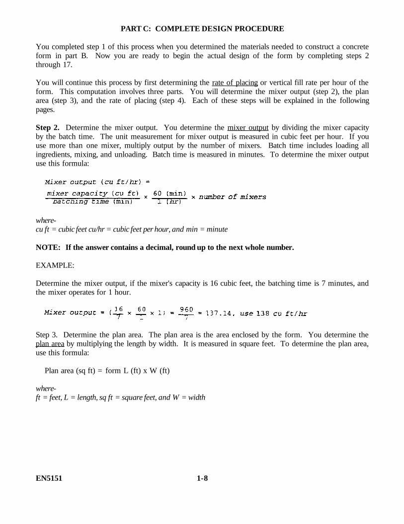
PART C: COMPLETE DESIGN PROCEDURE
You completed step 1 of this process when you determined the materials needed to construct a concreteform in part B. Now you are ready to begin the actual design of the form by completing steps 2through 17.
You will continue this process by first determining the rate of placing or vertical fill rate per hour of theform. This computation involves three parts. You will determine the mixer output (step 2), the planarea (step 3), and the rate of placing (step 4). Each of these steps will be explained in the followingpages.
Step 2. Determine the mixer output. You determine the mixer output by dividing the mixer capacityby the batch time. The unit measurement for mixer output is measured in cubic feet per hour. If youuse more than one mixer, multiply output by the number of mixers. Batch time includes loading allingredients, mixing, and unloading. Batch time is measured in minutes. To determine the mixer outputuse this formula:
where-cu ft = cubic feet cu/hr = cubic feet per hour, and min = minute
NOTE: If the answer contains a decimal, round up to the next whole number.
EXAMPLE:
Determine the mixer output, if the mixer's capacity is 16 cubic feet, the batching time is 7 minutes, andthe mixer operates for 1 hour.
Step 3. Determine the plan area. The plan area is the area enclosed by the form. You determine theplan area by multiplying the length by width. It is measured in square feet. To determine the plan area,use this formula:
Plan area (sq ft) = form L (ft) x W (ft)
where-ft = feet, L = length, sq ft = square feet, and W = width
EN5151 1-8

EXAMPLE:
Determine the plan area for a concrete wall form that is 15 feet long by 2 feet wide by 6 feet high.
Plan area = 15 x 2= 30 sq ft
Step 4. Determine the rate of placing. Having determined the mixer output (step 2) and the plan area(step 3), it is now time to compute the rate of placing. You determine the rate of placing of concrete inthe form by dividing the mixer output by the plan area. Rate of placing is measured in vertical feet perhour. To determine the rate of placing, use this formula and the following procedures:
where-ft/hr = feet per hour and R = rate of placing
• If the answer contains a decimal, round off to one decimal place. For example, for 1.41, use1.4; for 1.57, use 1.6.
• The rates of placing should be kept below 5 feet/hour for economical design. Rate of placing<5 feet/hour.
EXAMPLE:
Determine the rate of placing if the mixer output is 7 cubic yards per hour (189 cubic feet/hour) and theplan area is 15 feet by 2 feet.
1-9 EN5151

Work the following problems to see how well you understand the concepts you just covered in steps 2,3, and 4. See page 1-31 for the solution to each problem.
PROBLEM 6
Determine the plan area for a form that is 33 feet long by 7.5 feet high by 3 feet wide.
A. 30
B. 33
C. 66
D. 99
PROBLEM 7
Determine the total mixer output if the mixer capacity is 16 cubic feet and the batching time is 6minutes with two mixers operating for 1 hour.
A. 290
B. 308
C. 320
D. 328
PROBLEM 8
Determine the rate of placing if the mixer output is 7 cubic yard per hour (189 cubic feet per hour) andthe plan area is 33 feet by 3 feet.
A. 0.8
B. 1.9
C. 2.3
D. 3.1
EN5151 1-10
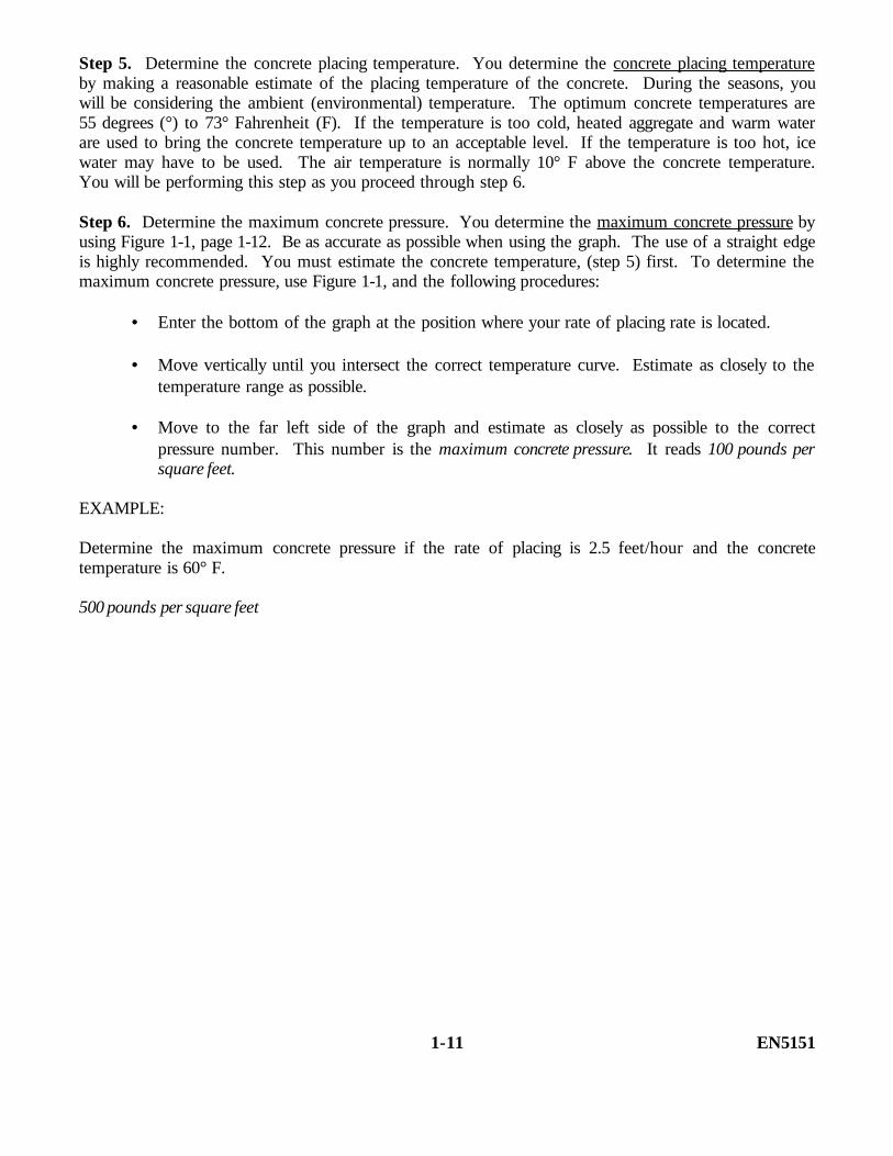
Step 5. Determine the concrete placing temperature. You determine the concrete placing temperatureby making a reasonable estimate of the placing temperature of the concrete. During the seasons, youwill be considering the ambient (environmental) temperature. The optimum concrete temperatures are55 degrees (°) to 73° Fahrenheit (F). If the temperature is too cold, heated aggregate and warm waterare used to bring the concrete temperature up to an acceptable level. If the temperature is too hot, icewater may have to be used. The air temperature is normally 10° F above the concrete temperature.You will be performing this step as you proceed through step 6.
Step 6. Determine the maximum concrete pressure. You determine the maximum concrete pressure byusing Figure 1-1, page 1-12. Be as accurate as possible when using the graph. The use of a straight edgeis highly recommended. You must estimate the concrete temperature, (step 5) first. To determine themaximum concrete pressure, use Figure 1-1, and the following procedures:
• Enter the bottom of the graph at the position where your rate of placing rate is located.
• Move vertically until you intersect the correct temperature curve. Estimate as closely to thetemperature range as possible.
• Move to the far left side of the graph and estimate as closely as possible to the correctpressure number. This number is the maximum concrete pressure. It reads 100 pounds persquare feet.
EXAMPLE:
Determine the maximum concrete pressure if the rate of placing is 2.5 feet/hour and the concretetemperature is 60° F.
500 pounds per square feet
1-11 EN5151

Figure 1-1. Maximum concrete pressure graph
For more accurate determination of maximum concrete pressure, use the following formula:
NOTE: This formula will be used in place of Figure 1-1 when determining maximum concretepressure throughout the subcourse and in the examination.
EN5151 1-12
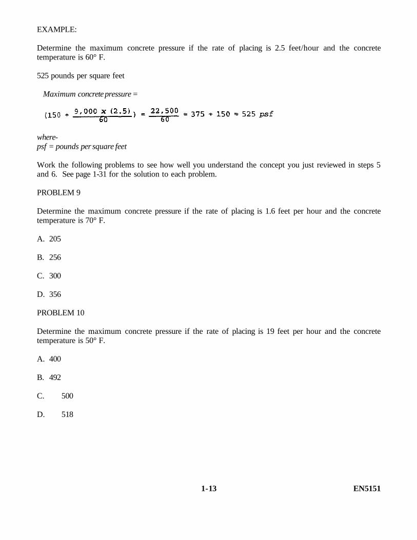
EXAMPLE:
Determine the maximum concrete pressure if the rate of placing is 2.5 feet/hour and the concretetemperature is 60° F.
525 pounds per square feet
Maximum concrete pressure =
where-psf = pounds per square feet
Work the following problems to see how well you understand the concept you just reviewed in steps 5and 6. See page 1-31 for the solution to each problem.
PROBLEM 9
Determine the maximum concrete pressure if the rate of placing is 1.6 feet per hour and the concretetemperature is 70° F.
A. 205
B. 256
C. 300
D. 356
PROBLEM 10
Determine the maximum concrete pressure if the rate of placing is 19 feet per hour and the concretetemperature is 50° F.
A. 400
B. 492
C. 500
D. 518
1-13 EN5151
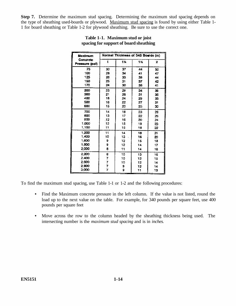
Step 7. Determine the maximum stud spacing. Determining the maximum stud spacing depends onthe type of sheathing used-boards or plywood. Maximum stud spacing is found by using either Table 1-1 for board sheathing or Table 1-2 for plywood sheathing. Be sure to use the correct one.
Table 1-1. Maximum stud or joistspacing for support of board sheathing
To find the maximum stud spacing, use Table 1-1 or 1-2 and the following procedures:
• Find the Maximum concrete pressure in the left column. If the value is not listed, round theload up to the next value on the table. For example, for 340 pounds per square feet, use 400pounds per square feet
• Move across the row to the column headed by the sheathing thickness being used. Theintersecting number is the maximum stud spacing and is in inches.
EN5151 1-14
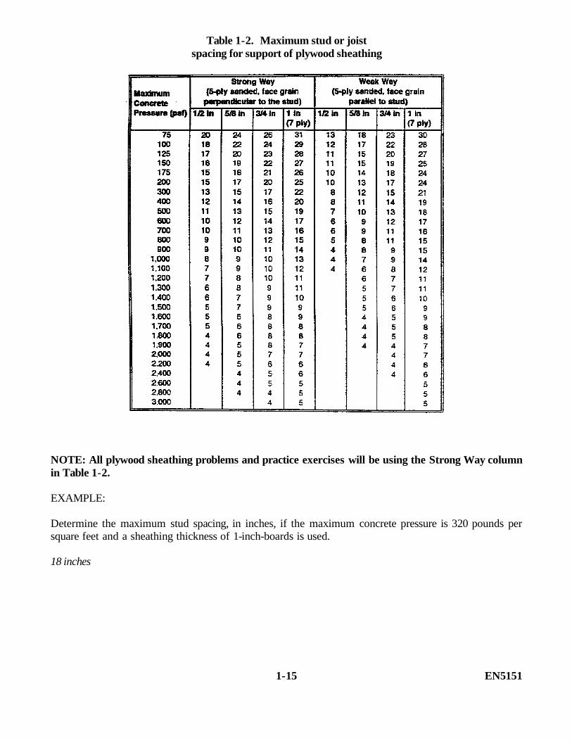
Table 1-2. Maximum stud or joistspacing for support of plywood sheathing
NOTE: All plywood sheathing problems and practice exercises will be using the Strong Way columnin Table 1-2.
EXAMPLE:
Determine the maximum stud spacing, in inches, if the maximum concrete pressure is 320 pounds persquare feet and a sheathing thickness of 1-inch-boards is used.
18 inches
1-15 EN5151
Work the following problem to see how well you understand the concept you just reviewed in step 7.See page 1-31 for the solution in this problem.
PROBLEM 11
Determine the maximum stud spacing, in inches, if the maximum concrete pressure is 700 pounds persquare feet and sheathing thickness of 1-inch boards is used.
A. 14
B. 15
C. 16
D. 21
EN5151 1-16

Step 8. Determine the uniform load on a stud. You determine the uniform load on a stud bymultiplying the maximum concrete pressure (step 6) by the stud spacing (step 7). Uniform load on astud is measured in pounds per linear feet. To determine uniform load on a stud, use this formula andthe following procedures:
where to-in = inch, lb/lin ft = pounds per linear feet, lb/sq ft = pounds per square feet and ULS =uniform load on a stud
• Use the actual concrete pressure, not the rounded up figure that was used to obtain the studspacing in step 7.
• Carry out the answer two decimal places.
EXAMPLE:
Determine the uniform load on a stud if the maximum concrete pressure is 410 pounds per square feetand the maximum stud spacing is 18 inches.
Work the following problem to see how well you understand the concept you just reviewed in step 8.See page 1-31 for the solution to this problem.
PROBLEM-12
Determine the uniform load on a stud if maximum concrete pressure is 350 pounds per square feet andthe maximum stud spacing is 20 inches.
A. 350.38B. 560.70C. 583.33D. 593.35
1-17 EN5151
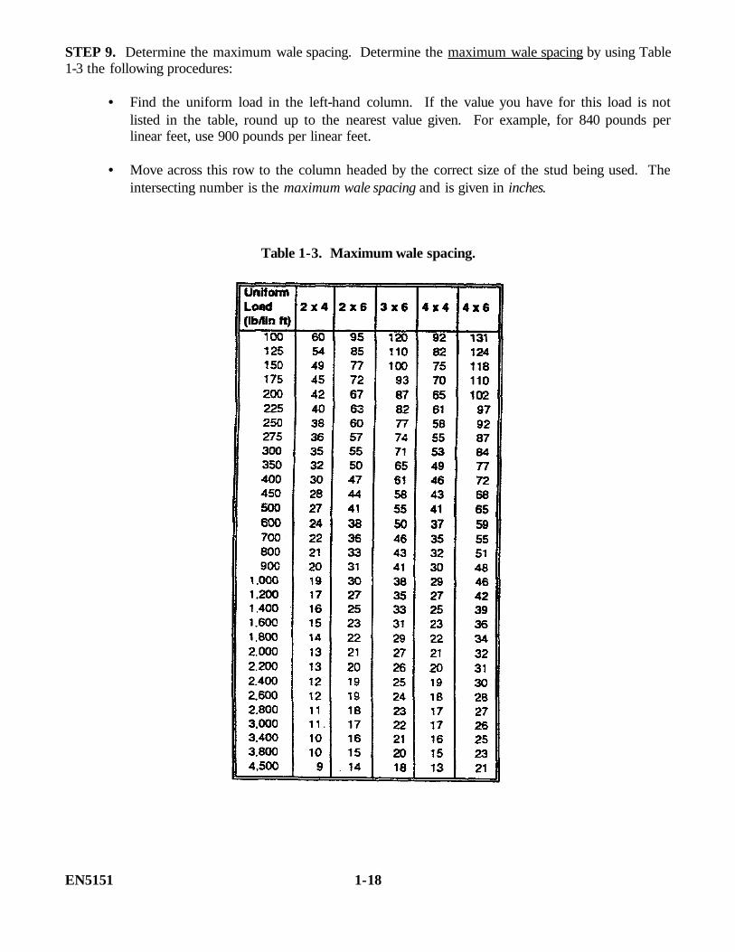
STEP 9. Determine the maximum wale spacing. Determine the maximum wale spacing by using Table1-3 the following procedures:
• Find the uniform load in the left-hand column. If the value you have for this load is notlisted in the table, round up to the nearest value given. For example, for 840 pounds perlinear feet, use 900 pounds per linear feet.
• Move across this row to the column headed by the correct size of the stud being used. Theintersecting number is the maximum wale spacing and is given in inches.
Table 1-3. Maximum wale spacing.
EN5151 1-18

EXAMPLE:
Find the maximum wale spacing if the uniform load is 1,560 pounds per linear feet and the studs are 2by 6 inches.
23 inches
Work the following problem to see how well you understand the concept you just reviewed in step 9.See page 1-31 for the solution to this problem.
PROBLEM 13
Find the maximum wale spacing if the uniform load is 581 pounds per linear feet and the studs are 2 by4 inches.
A. 19B. 22C. 24D. 27
1-19 EN5151

Step 10. Determine the uniform load on a wale. You determine the uniform load on a wale bymultiplying the maximum concrete pressure (step 6) by the maximum wale spacing (step 9). Uniformload on a wale is measured in pounds per linear foot. To determine the uniform load on a wale, usethis formula and the following procedures:
ULW (lb/lin ft) =maximum concrete pressure (psf) x maximum wale spacing (in) 12 (in/ft)where-ULW = uniform load on a wale
• Use the actual concrete pressure, not the rounded off figure that you used to obtain the walespacing (step 9).
• Carry out your answer two decimal places.
EXAMPLE:
Determine the uniform load on a wale if the maximum concrete pressure is 550 pounds per square feetand the maximum wale spacing is 20 inches.
Work the following problem to see how well you understand the concept you just reviewed in step 10.See page 1-31 for the solution to this problem.
PROBLEM 14
Determine the uniform load on a wale if the maximum concrete pressure is 350 pounds per square feetand the maximum wale spacing is 26 inches.
A. 350.83
B. 758.33
C. 780.53
D. 810.66
EN5151 1-20

To determine the tie wire spacing, you will need to perform the steps sequentially. First, compute tiewire spacing based on wale size (step 11). Next, you will need to compute the tie wire spacing based ontie wire strength (step 12). Last, compare the two to select the maximum allowable tie wire spacing (step13). The following pages will cover each of these steps.
Step 11. Determine tie wire spacing based on wale size. Tie wire spacing based on wale size is foundby using Table 1-4. The sizes at the top of the table refer to the wale material being used. The table isdivided into two halves, single-wale members located on the left, and double-wale members on the right.
Table 1-4. Maximum spacing of supporting members(wales, ties, stringers, and 4- by 4-inch and larger shores)
1-21 EN5151

To find the tie-wire spacing, use Table 1-4, page 1-21 and the following procedures:
• Find the uniform load on a wale in the left-hand column of the table. If the value you havefor this load is not listed in the table, round up to the nearest value given. For example, for1,250 pounds per linear feet, use 1,400 ponds per linear feet.
• Move across this row to either the single- or double-wale members section. Then locate thewale size that you will be using. The intersecting number is the tie-wire spacing, in inches,based on wale size.
EXAMPLE:
Determine the tie-wire spacing in inches, if the uniform load on a wale is 125 pounds per linear feet and4- by 4-single wales are used.
82 inches
Work the following problem to see how well you understand the concept you just reviewed in step 11.See page 1-31 for the solution to this problem.
PROBLEM 15
Determine the tie wire spacing, in inches, if the uniform load is 756 pounds per linear feet and 2- by 4-double wales are used.
A. 30
B. 43
C. 46
D. 72
EN5151 1-22
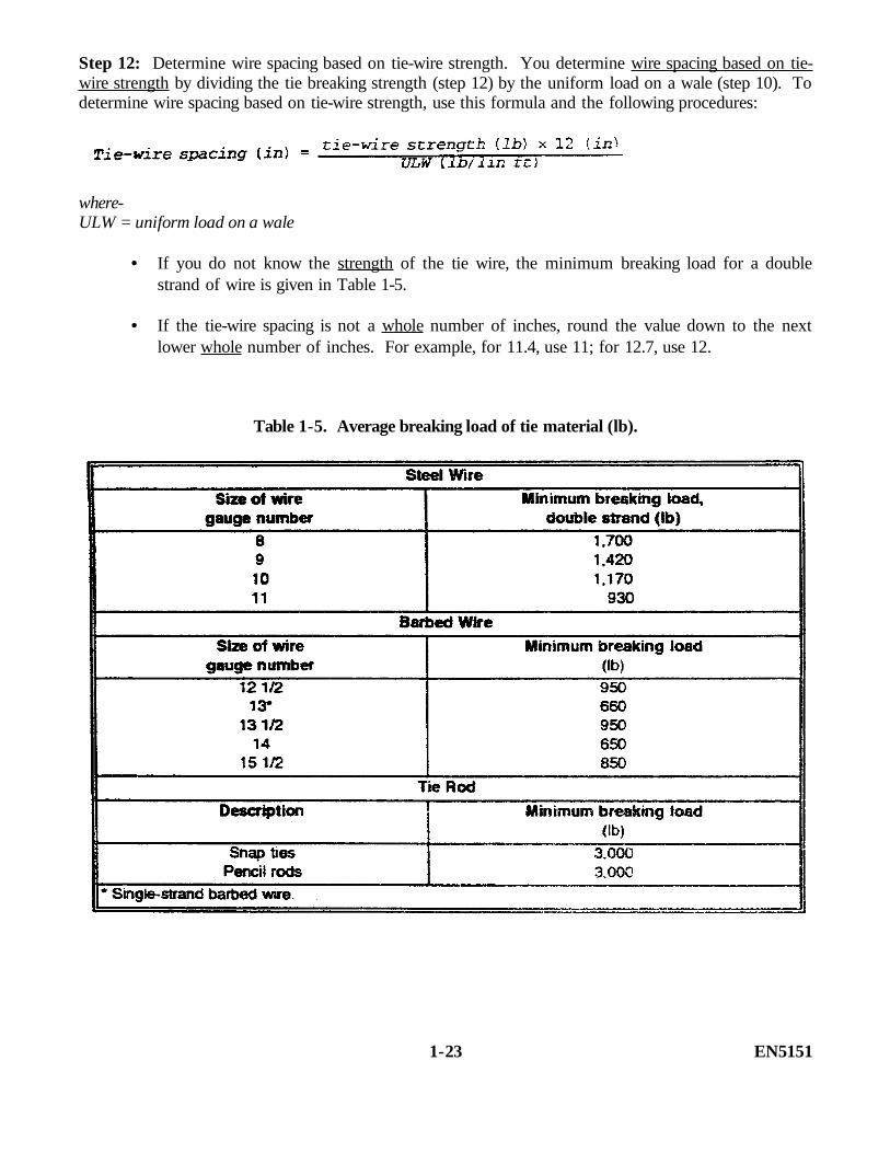
Step 12: Determine wire spacing based on tie-wire strength. You determine wire spacing based on tie-wire strength by dividing the tie breaking strength (step 12) by the uniform load on a wale (step 10). Todetermine wire spacing based on tie-wire strength, use this formula and the following procedures:
where-ULW = uniform load on a wale
• If you do not know the strength of the tie wire, the minimum breaking load for a doublestrand of wire is given in Table 1-5.
• If the tie-wire spacing is not a whole number of inches, round the value down to the nextlower whole number of inches. For example, for 11.4, use 11; for 12.7, use 12.
Table 1-5. Average breaking load of tie material (lb).
1-23 EN5151
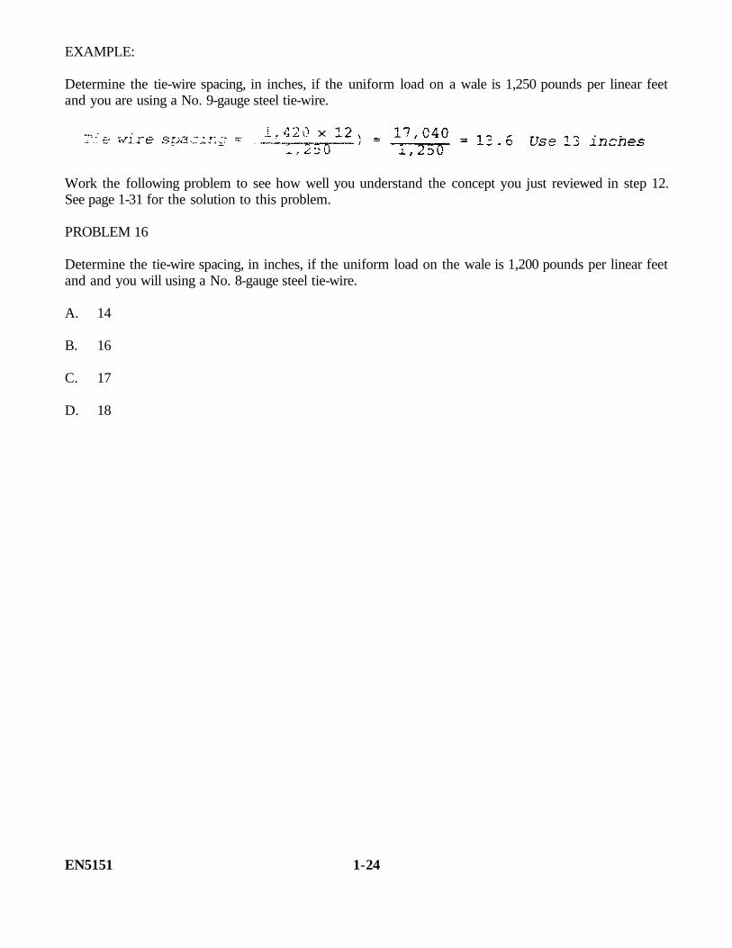
EXAMPLE:
Determine the tie-wire spacing, in inches, if the uniform load on a wale is 1,250 pounds per linear feetand you are using a No. 9-gauge steel tie-wire.
Work the following problem to see how well you understand the concept you just reviewed in step 12.See page 1-31 for the solution to this problem.
PROBLEM 16
Determine the tie-wire spacing, in inches, if the uniform load on the wale is 1,200 pounds per linear feetand and you will using a No. 8-gauge steel tie-wire.
A. 14
B. 16
C. 17
D. 18
EN5151 1-24
Step 13. Determine the maximum tie-wire spacing. You determine the maximum tie-wire spacing bycomparing the results from steps 11 and 12, then use the smaller of the two tie-wire spacings as themaximum tie wire spacing.
EXAMPLE:
Determine the maximum tie-wire spacing value by comparing the following measurement:
• Tie-wire spacing based on wale size = 24 inches
• Tie-wire spacing based on wire strength = 20 inches
Use the smaller tie wire spacing (20 inches).
PROBLEM 17
Work the following problem to see how well you understand the concept you just reviewed in step 13.See page 1-32 for the solution to this problem.
Determine the maximum tie-wire spacing value by comparing the following measurement:
• 16 inches (based on wire strength)
• 26 inches (based on wale size)
1-25 EN5151

STEP 14. Determine the location of the ties. Now that you have obtained the maximum stud spacing(step 7) and the maximum tie wire spacing (step 13), it is time to compare the two. The correct location(spacing) of your ties must be determined to ensure that the form design has the proper strength.
NOTE: This step is performed only when using wires. If you use snap ties, the spacing was found instep 13.
Determining the location of the ties requires consideration of two factors when comparing stud spacingand tie wire spacing:
• If the maximum tie spacing is less than the maximum stud spacing, reduce the maximumstud spacing to equal the maximum tie-wire spacing and install the tie at the intersections ofthe studs and wales or get a stronger wire.
• If the maximum tie spacing is greater than or equal to the maximum stud spacing, use thesize for the maximum stud spacing and install the tie at the intersections of the studs andwales.
EXAMPLE:
Determine where the ties will be made if the maximum stud spacing is 28 inches and the maximum tiewire spacing is 24 inches.
• 28 inches (expand stud spacing)
• 24 inches (reduce stud spacing)
Reduce the stud spacing to 24 inches and install the tie at the intersections of the studs and wales.
Work the following problem to see how well you understand the concept you just reviewed in step 14.See page 1-32 for the solution to this problem.
PROBLEM 18
Determine where the ties will be made if the maximum stud spacing is 14 inches and the maximum tiewire spacing is 20 inches.
• 14 inches (reduce stud spacing)
• 20 inches (expand stud spacing)
EN5151 1-26

Step 15. Determine the number of studs for one side. You determine the number of studs for oneside of a form by dividing the form length by the maximum stud spacing (step 7 or step 14 if studspacing has been reduced). Add one to this number, and round up to the next value if your answercontains decimal. Your first and last studs must be placed at the ends of the form, even though thespacing between the last two studs may be less than the maximum allowable spacing. To determine thenumber of studs for one side of the form, use this formula and the following procedures:
• If your answer contains a decimal, round up to the next whole number.
• The spacing between the last two studs may be less than the maximum allowable spacing.
EXAMPLE:
Determine how many studs are required for one side of the form if the stud spacing is 24 inches andthe form length is 28 feet.
Work the following problem to see how well you understand the concept you just reviewed, in step 15.See page 1-32 for the solution to this problem.
PROBLEM 19
Determine how many studs are required for one side of the form if the stud spacing is 14 inches andthe form length is 24 feet.
A. 19
B. 20
C. 21
D. 22
1-27 EN5151
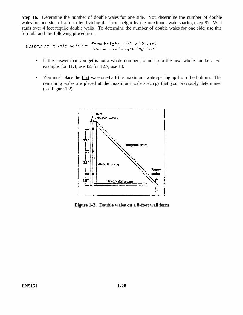
Step 16. Determine the number of double wales for one side. You determine the number of doublewales for one side of a form by dividing the form height by the maximum wale spacing (step 9). Wallstuds over 4 feet require double walls. To determine the number of double wales for one side, use thisformula and the following procedures:
• If the answer that you get is not a whole number, round up to the next whole number. Forexample, for 11.4, use 12; for 12.7, use 13.
• You must place the first wale one-half the maximum wale spacing up from the bottom. Theremaining wales are placed at the maximum wale spacings that you previously determined(see Figure 1-2).
Figure 1-2. Double wales on a 8-foot wall form
EN5151 1-28

EXAMPLE:
Determine how many wales are required for one side of the form if the wale spacing is 32 inches and aform height of 8 feet is used.
Work the following problems to see how well you understand the concept you just reviewed in step 16.See page 1-32 for the solution to this problem.
PROBLEM 20
Determine how many wales are required for one side of the form if the wale spacing is 30 inches andthe form height is 8 feet.
A. 1
B. 2
C. 3
D. 4
1-29 EN5151
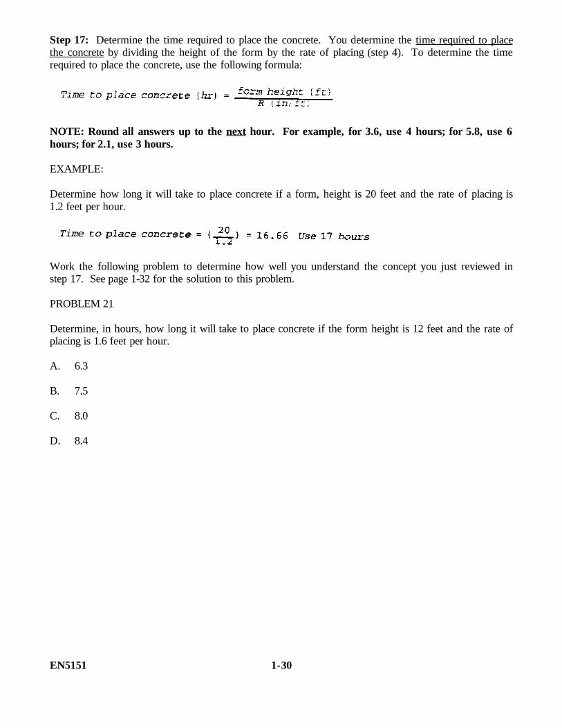
Step 17: Determine the time required to place the concrete. You determine the time required to placethe concrete by dividing the height of the form by the rate of placing (step 4). To determine the timerequired to place the concrete, use the following formula:
NOTE: Round all answers up to the next hour. For example, for 3.6, use 4 hours; for 5.8, use 6hours; for 2.1, use 3 hours.
EXAMPLE:
Determine how long it will take to place concrete if a form, height is 20 feet and the rate of placing is1.2 feet per hour.
Work the following problem to determine how well you understand the concept you just reviewed instep 17. See page 1-32 for the solution to this problem.
PROBLEM 21
Determine, in hours, how long it will take to place concrete if the form height is 12 feet and the rate ofplacing is 1.6 feet per hour.
A. 6.3
B. 7.5
C. 8.0
D. 8.4
EN5151 1-30

PROBLEMS ANSWER KEY AND FEEDBACK
Problem Correct Answer
1. A. 3/4-inch plywood and 1- by 6-inch material (page 1-5)
2. C. 2- by 6-inch and 2- by 4-inch material (page 1-5)
3. D. 2- by 4-inch and 4- by 4-inch material (page 1-5)
4. D. 4- by 4-inch and 2- by 4-inch material (page 1-5)
5. C. No. 8 and No. 9 annealed wire (page 1-5)
6. D. 99. Plan area = 33 x 3 = 99 square feet (page 1-8)
7.
8.
9.
10.
11. A. 14 inches (page 1-14)
12.
13. C. 24 inches (page 1-18)
14.
15. A. 30 inches (page 1-21)
16.
1-31 EN5151
PROBLEMS ANSWER KEY AND FEEDBACK CONT.
Problem Correct Answer
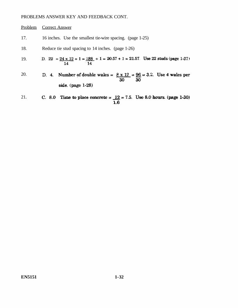
17. 16 inches. Use the smallest tie-wire spacing. (page 1-25)
18. Reduce tie stud spacing to 14 inches. (page 1-26)
19.
20.
21.
EN5151 1-32

PRACTICE EXERCISE
The following items will test your grasp of the material covered in this lesson. There is only one correctanswer for each item. When you have completed the exercise, check your answers with the key thatfollows. If you answer any item incorrectly, study again that part which contain the portion involved.
There are two problems for this exercise. You will be performing them step by step as you did duringthe lesson. Step 1, materials to be selected, has been completed for you and appears in each of theproblem statements.
Problem 1. You will be designing a form work for a concrete wall that is to be 5 feet high, 140 feetlong, and 18 inches thick. You will have three 16-S mixers with a 16 cubic foot capacity to use forconcrete mixing. Each has a batch cycle of 3 minutes. The concrete temperature expected to be 80° F.Materials available are: 1-by 12-inch-boards, 2-by 4-inch studs, 2-by 4-inch doubled wales, and 3,000-pound snap ties.
1. Determine, in cubic feet per hour, the total mixer output if the mixer capacity is 16 cubic feet,batching time is 3 minutes, and the 3 mixers will be operating for 1 hour.
A. 960
B. 840
C. 3,200
D. 7,400
2. Determine the plan area for a concrete wall form that is 140 feet long, 5 feet high and 18 inchesthick.
A. 140
B. 180
C. 210
D. 250
1-33 EN5151

3. Determine the rate of placing, in feet per hour.
A. 3.8
B. 4.6
C. 5.0
D. 5.6
4. Determine the concrete temperature.
A. 60
B. 70
C. 80
D. 90
5. Determine the maximum concrete pressure, in pounds per square feet.
A. 600.3
B. 630.6
C. 667.5
D. 750.5
6. Determine the maximum stud spacing, in pounds per square feet.
A. 13
B. 14
C. 15
D. 16
EN5151 1-34

7. Determine the uniform load on a stud, in pounds per linear feet.
A. 678.3
B. 738.5
C. 778.7
D. 828.5
8. Determine the maximum wale spacing, in inches.
A. 20
B. 21
C. 22
D. 24
9. Determine the uniform load on a wale, in pounds per linear feet.
A. 1,168.13
B. 1,268.25
C. 1,325.35
D. 1,362.73
10. Determine the tie-wire spacing, based on wale size.
A. 21
B. 23
C. 25
D. 35
1-35 EN5151
11. Determine the tie-wire spacing, based on tie wire strength.
A. 26
B. 28
C. 32
D. 30
12. Determine the maximum tie-wire spacing, in inches.
A. 21
B. 25
C. 23
D. 26
13. Determine the adjusted tie-wire/stud spacing.
A. 18
B. 20
C. 25
D. Does not apply for snap ties
14. Determine how many studs are required for one side of the form.
A. 121
B. 122
C. 126
D. 131
EN5151 1-36
15. Determine how many double wales will be required for one side.
A. 2
B. 3
C. 4
D. 5
16. Determine the time required to place the concrete, in hours.
A. 0.5
B. 1.0
C. 1.5
D. 2.0
1-37 EN5151
Problem 2. You will be designing a form work for a concrete wall that is to be 6.5 feet high, 92 feetlong, and 12 inches thick. You will have one M919 mobile mixer with 27-cubic-foot capacity to use forconcrete mixing. It has a 1-cubic-yard batch cycle for every four minutes. The concrete temperature isexpected to be 50° F. Materials available are: 5/8-inch-plywood sheathing, 2- by 4-inch lumber forstuds, 4- by 4-inch lumber for wales, and No. 9 wire for ties.
17. Determine the total mixer output in cubic feet per hour, if the mixer capacity is 27 cubic feet (1cubic yard) with batching time of four minutes and you have one mixer operating for an hour.
A. 310
B. 405
C. 435
D. 450
18. Determine the plan area, in square feet, for a concrete wall form that is 92 feet long, 6.5 feet high,and 12 inches thick.
A. 46
B. 92
C. 112
D. 598
EN5151 1-38

19. Determine the rate of placing, in feet per hour.
A. 3.8
B. 4.4
C. 4.6
D. 5.6
20. Determine the concrete temperature.
A. 50
B. 60
C. 70
D. 80
21. Determine the maximum concrete pressure, in pounds per square feet.
A. 667
B. 750
C. 842
D. 942
1-39 E5151
22. Determine the maximum stud spacing, in pounds per square feet.
A. 6
B. 7
C. 8
D. 9
23. Determine the uniform load on a stud, in pounds per linear feet.
A. 678.5
B. 706.5
C. 738.5
D. 828.5
24. Determine the maximum wale spacing, in inches.
A. 20
B. 21
C. 22
D. 24
EN5151 1-40
25. Determine the uniform load on the wale, pounds per linear feet.
A. 1,325.5
B. 1,468.5
C. 1,568.5
D. 1,648.5
26. Determine the tie-wire spacing, based on wale size.
A. 21
B. 22
C. 23
D. 25
27. Determine the tie-wire spacing, based on tie-wire strength.
A. 8
B. 10
C. 12
D. 14
1-41 EN5151
28. Determine the maximum tie-wire spacing, in inches.
A. 8
B. 9
C. 10
D. 11
29. Determine the adjusted tie-wire/stud spacing, in inches.
A. 6
B. 8
C. 9
D. 10
30. Determine how many studs are required for one side of the form.
A. 120
B. 121
C. 124
D. 126
EN5151 1-42

31. Determine how many double wales will be required for one side.
A. 2
B. 3
C. 4
D. 5
32. Determine the time required to place the concrete, in hours.
A. 0.5
B. 1.0
C. 1.5
D. 2.0
1-43 EN5151
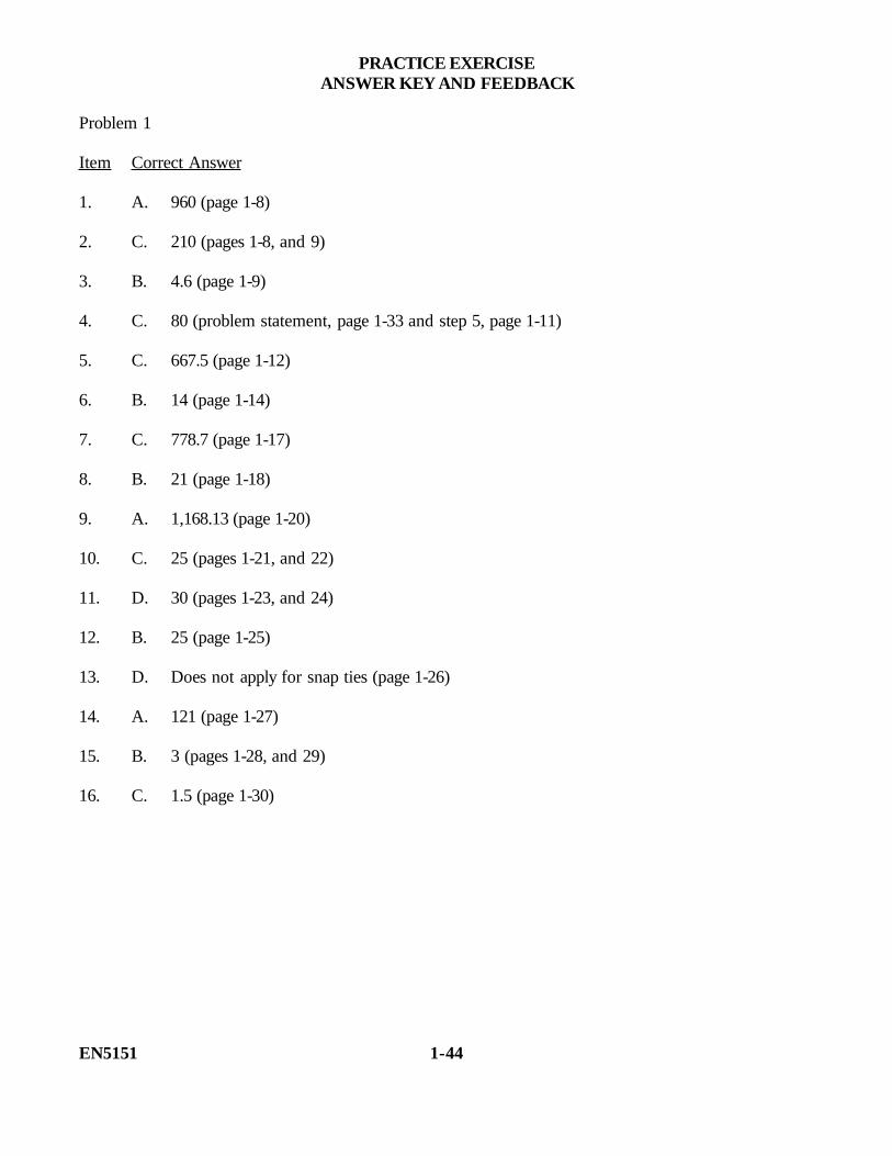
PRACTICE EXERCISEANSWER KEY AND FEEDBACK
Problem 1
Item Correct Answer
1. A. 960 (page 1-8)
2. C. 210 (pages 1-8, and 9)
3. B. 4.6 (page 1-9)
4. C. 80 (problem statement, page 1-33 and step 5, page 1-11)
5. C. 667.5 (page 1-12)
6. B. 14 (page 1-14)
7. C. 778.7 (page 1-17)
8. B. 21 (page 1-18)
9. A. 1,168.13 (page 1-20)
10. C. 25 (pages 1-21, and 22)
11. D. 30 (pages 1-23, and 24)
12. B. 25 (page 1-25)
13. D. Does not apply for snap ties (page 1-26)
14. A. 121 (page 1-27)
15. B. 3 (pages 1-28, and 29)
16. C. 1.5 (page 1-30)
EN5151 1-44
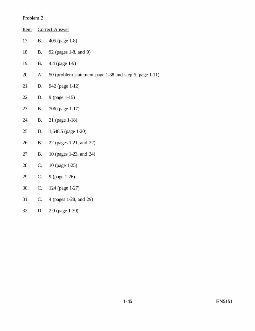
Problem 2
Item Correct Answer
17. B. 405 (page 1-8)
18. B. 92 (pages 1-8, and 9)
19. B. 4.4 (page 1-9)
20. A. 50 (problem statement page 1-38 and step 5, page 1-11)
21. D. 942 (page 1-12)
22. D. 9 (page 1-15)
23. B. 706 (page 1-17)
24. B. 21 (page 1-18)
25. D. 1,648.5 (page 1-20)
26. B. 22 (pages 1-21, and 22)
27. B. 10 (pages 1-23, and 24)
28. C. 10 (page 1-25)
29. C. 9 (page 1-26)
30. C. 124 (page 1-27)
31. C. 4 (pages 1-28, and 29)
32. D. 2.0 (page 1-30)
1-45 EN5151

THIS PAGE IS INTENTIONALLY LEFT BLANK
EN5151 1-46