DESIGN FOR NONSTRUCTURAL COMPONENTSrichardson.eng.ua.edu/Former_Courses/Wind_and_Seismic_fa...13-1...
35
13-1 13 DESIGN FOR NONSTRUCTURAL COMPONENTS Robert Bachman, P.E. and Richard Drake, P.E. Chapter 6 of the 2000 NEHRP Recommended Provisions and Commentary (hereinafter, the Provisions and Commentary) addresses architectural, mechanical, and electrical components of buildings. Two examples are presented here to illustrate many of the requirements and procedures. Design and anchorage are illustrated for exterior precast concrete cladding, and for a roof-mounted HVAC unit. The rooftop unit is examined in two common installations: directly attached, and isolated with snubbers. This chapter also contains an explanation of the fundamental aspects of the Provisions, and an explanation of how piping, designed according to the ASME Power Piping code, is checked for the force and displacement requirements of the Provisions. A large variety of materials and industries are involved with nonstructural components is large, and numerous documents define and describe methods of design, construction, manufacture, installation, attachment, etc. Some of the documents address seismic issues but many do not. Provisions Sec. 6.1.1 [6.1.2] contains a listing of approved standards for various nonstructural components. Although the Guide is based on the 2000 Provisions, it has been annotated to reflect changes made to the 2003 Provisions. Annotations within brackets, [ ], indicate both organizational changes (as a result of a reformat of all of the chapters of the 2003 Provisions) and substantive technical changes to the 2003 Provisions and its primary reference documents. While the general concepts of the changes are described, the design examples and calculations have not been revised to reflect the changes to the 2003 Provisions. A few noteworthy changes were made to the nonstructural components requirements of the 2003 Provisions. These include explicit definition of load effects (including vertical seismic forces) within the chapter and revised classification of nonductile anchors (based on demonstrated ductility or prequalification rather than embedment-length-to-diameter ratio). In addition to changes Provisions Chapter 6, the basic earthquake hazard maps were updated and the concrete design reference was updated to ACI 318-02 (with a significant resulting changes to the calculations for anchors in concrete). Where they affect the design examples in this chapter of the Guide, significant changes to the 2003 Provisions and primary reference documents are noted. However, some minor changes to the 2003 Provisions and the reference documents may not be noted. In addition to the Provisions, the following are referenced in this chapter:
-
Upload
nguyenkien -
Category
Documents
-
view
221 -
download
1
Transcript of DESIGN FOR NONSTRUCTURAL COMPONENTSrichardson.eng.ua.edu/Former_Courses/Wind_and_Seismic_fa...13-1...

13-1
13DESIGN FOR
NONSTRUCTURAL COMPONENTSRobert Bachman, P.E. and Richard Drake, P.E.
Chapter 6 of the 2000 NEHRP Recommended Provisions and Commentary (hereinafter, the Provisionsand Commentary) addresses architectural, mechanical, and electrical components of buildings. Twoexamples are presented here to illustrate many of the requirements and procedures. Design and anchorageare illustrated for exterior precast concrete cladding, and for a roof-mounted HVAC unit. The rooftopunit is examined in two common installations: directly attached, and isolated with snubbers. This chapteralso contains an explanation of the fundamental aspects of the Provisions, and an explanation of howpiping, designed according to the ASME Power Piping code, is checked for the force and displacementrequirements of the Provisions.
A large variety of materials and industries are involved with nonstructural components is large, andnumerous documents define and describe methods of design, construction, manufacture, installation,attachment, etc. Some of the documents address seismic issues but many do not. Provisions Sec. 6.1.1 [6.1.2] contains a listing of approved standards for various nonstructural components.
Although the Guide is based on the 2000 Provisions, it has been annotated to reflect changes made to the2003 Provisions. Annotations within brackets, [ ], indicate both organizational changes (as a result of areformat of all of the chapters of the 2003 Provisions) and substantive technical changes to the 2003Provisions and its primary reference documents. While the general concepts of the changes aredescribed, the design examples and calculations have not been revised to reflect the changes to the 2003Provisions.
A few noteworthy changes were made to the nonstructural components requirements of the 2003Provisions. These include explicit definition of load effects (including vertical seismic forces) within thechapter and revised classification of nonductile anchors (based on demonstrated ductility orprequalification rather than embedment-length-to-diameter ratio). In addition to changes Provisions Chapter 6, the basic earthquake hazard maps were updated and theconcrete design reference was updated to ACI 318-02 (with a significant resulting changes to thecalculations for anchors in concrete).
Where they affect the design examples in this chapter of the Guide, significant changes to the 2003Provisions and primary reference documents are noted. However, some minor changes to the 2003Provisions and the reference documents may not be noted.
In addition to the Provisions, the following are referenced in this chapter:
FEMA 451, NEHRP Recommended Provisions: Design Examples
13-2
ACI 318 American Concrete Institute. 1999 [2002]. Building Code Requirements andCommentary for Reinforced Concrete.
ASCE 7 American Society of Civil Engineers. 1998 [2002]. Minimum Design Loads forBuildings and Other Structures.
ASHRAE APP IP American Society of Heating, Refrigeration, and Air-Conditioning Engineers(ASHRAE). 1999. Seismic and Wind Restraint Design, Chapter 53.
ASME B31.1 American Society of Mechanical Engineers. Power Piping Code.
IBC International Code Council. 2000. International Building Code.
The symbols used in this chapter are drawn from Chapter 2 of the Provisions or reflect commonengineering usage. The examples are presented in U.S. customary units.
[In the 2003 Provisions, definitions and symbols specific to nonstructural components appear in Sec.6.1.3 and 6.1.4, respectively.]
13.1 DEVELOPMENT AND BACKGROUND OF THE PROVISIONS FORNONSTRUCTURAL COMPONENTS
13.1.1 Approach to Nonstructural Components
The Provisions requires that nonstructural components be checked for two fundamentally differentdemands placed upon them by the response of the structure to earthquake ground motion: resistance toinertial forces and accommodation of imposed displacements. Building codes have long hadrequirements for resistance to inertial forces. Most such requirements apply to the component mass anacceleration that vary with the basic ground motion parameter and a few broad categories of components. The broad categories are intended distinguish between components whose dynamic response couples withthat of the supporting structure in such a fashion as to cause the component response accelerations to beamplified above the accelerations of the structure and those components that are rigid enough with respectto the structure so that the component response is not amplified over the structural response. In recentyears, a coefficient based on the function of the building or of the component have been introduced asanother multiplier for components important to life safety or essential facilities.
The Provisions includes an equation to compute the inertial force that involves two additional concepts:variation of the acceleration with relative height within the structure, and reduction in design force basedupon available ductility in the component, or its attachment. The Provisions also includes a quantitativemeasure for the deformation imposed upon nonstructural components. The inertial force demands tend tocontrol the seismic design for isolated or heavy components, whereas, the imposed deformations areimportant for the seismic design for elements that are continuous through multiple levels of a structure, oracross expansion joints between adjacent structures, such as cladding or piping.
The remaining portions of this section describe the sequence of steps and decisions prescribed by theProvisions to check these two seismic demands on nonstructural components.
13.1.2 Force Equations
The following seismic force equations are prescribed for nonstructural components:(Provisions Eq.6.1.3-1 [6.2-1], 6.1.3-2 [6.2-3], and 6.1.3-3 [6.2-4]):

Chapter 13, Nonstructural Components
13-3
0.41 2p DS p
pp
p
a S W zF R hI
⎛ ⎞= +⎜ ⎟⎝ ⎠
1.6maxp DS p pF S I W=
0.3minp DS p pF S I W=
where:
Fp = horizontal equivalent static seismic design force centered at the component’s center of gravityand distributed relative to the component’s mass distribution.
ap = component amplification factor (either 1.0 or 2.5) as tabulated in Provisions Table 6.2.2 [6.3-1]for architectural components and Provisions Table 6.3.2 [6.4-1] for mechanical and electricalcomponents (Alternatively, may be computed by dynamic analysis)
SDS = five percent damped spectral response acceleration parameter at short period as defined inProvisions Sec. 4.1.2 [3.3.3]
Wp = component operating weight
Rp = component response modification factor (varies from 1.0 to 5.0) as tabulated in ProvisionsTable 6.2.2 [6.3-1]for architectural components and Provisions Table 6.3.2 [6.4-1] formechanical and electrical components
Ip = component importance factor (either 1.0 or 1.5) as indicated in Provisions Sec. 6.1.5 [6.2-2]
z = elevation in structure of component point of attachment relative to the base
h = roof elevation of the structure or elevation of highest point of the seismic-force-resisting systemof the structure relative to the base
The seismic design force, Fp, is to be applied independently in the longitudinal, and transverse directions. The effects of these loads on the component are combined with the effects of static loads. Provisions Eq.6.1.3-2 [6.2-3 and 6.2-4] and 6.1.3-3, provide maximum and minimum limits for the seismic design force.
For each point of attachment, a force, Fp, should be determined based on Provisions Eq. 6.1.3-1 [6.2-1]. The minima and maxima determined from Provisions Eq. 6.1.3-2 and 6.1.3-3 [6.2-1] must be consideredin determining each Fp. The weight, Wp, used to determine each Fp should be based on the tributaryweight of the component associated with the point of attachment. For designing the component, theattachment force, Fp, should be distributed relative to the component’s mass distribution over the areaused to establish the tributary weight. With the exception of the bearing walls, which are covered byProvisions Sec. 5.2.6.2.7 [4.6.1.3], and out-of-plane wall anchorage to flexible diaphragms, which iscovered by Provisions Sec. 5.2.6.3.2 [4.6.2.1], each anchorage force should be based on simple staticsdetermined by using all the distributed loads applied to the complete component. Cantilever parapets thatare part of a continuous element, should be separately checked for parapet forces.
13.1.3 Load Combinations and Acceptance Criteria
FEMA 451, NEHRP Recommended Provisions: Design Examples
13-4
13.1.3.1 Seismic Load Effects
When the effects of vertical gravity loads and horizontal earthquake loads are additive, Provisions Eq.5.2.7.1-1 [4.2-1] is used:
E = ρQE + 0.2SDSD
When the effects of vertical gravity load counteract those of horizontal earthquake loads, Provisions Eq.5.2.7.1-2 [4.2-2] is used:
E = ρQE - 0.2SDSD
where:
E = effect of horizontal and vertical earthquake-induced forces
ρ = redundancy factor (= 1.0 for nonstructural components)
QE = effect of horizontal seismic forces (due to application of Fp for nonstructural components)
D = effect of dead load
0.2SDSD = effect of vertical seismic forces
13.1.3.2 Strength Load Combinations
Provisions Sec. 5.2.7 [4.2.2] requires the use of ASCE 7 factored load combinations. The combinationsfrom ASCE 7 Sec. 2.3.2 that include earthquake effects are:
U = 1.2D + 1.0E + 0.5L + 0.2S
U = 0.9D + 1.0E + 1.6H
13.1.4 Component Amplification Factor
The component amplification factor, ap, found in Provisions Eq. 6.1.3-1 [6.2-1] represents the dynamicamplification of the component relative to the maximum acceleration of the component support point(s). Typically, this amplification is a function of the fundamental period of the component, Tp, and thefundamental period of the support structure, T. It is recognized that at the time the components aredesigned or selected, the effective fundamental period of the structure, T, is not always available. It isalso recognized that for a majority of nonstructural components, the component fundamental period, Tp,can be accurately obtained only by expensive shake-table or pullback tests. As a result, the determinationof a component’s fundamental period by dynamic analysis, considering T/Tp ratios, is not alwayspracticable. For this reason, acceptable values of ap have been provided in the Provisions tables. Therefore, component amplification factors from either these tables or a dynamic analysis may be used. Values for ap are tabulated for each component based on the expectation that the component will behavein either a rigid or a flexible manner. For simplicity, a step function increase based on input motionamplifications is provided to help distinguish between rigid and flexible behavior. If the fundamentalperiod of the component is less than 0.06 seconds, no dynamic amplification is expected and ap may betaken to equal 1.00. If the fundamental period of the component is greater than 0.06 seconds, dynamicamplification is expected, and ap is taken to equal 2.50. In addition, a rational analysis determination of

Chapter 13, Nonstructural Components
13-5
ap is permitted if reasonable values of both T and Tp are available. Acceptable procedures for determiningap are provided in Commentary Chapter 6.
13.1.5 Seismic Coefficient at Grade
The short period design spectral acceleration, SDS, considers the site seismicity and local soil conditions. The site seismicity is obtained from the design value maps (or CD-ROM), and SDS is determined inaccordance with Provisions Sec. 4.1.2.5 [3.3.3]. The coefficient SDS is the used to design the structure. The Provisions approximates the effective peak ground acceleration as 0.4SDS, which is why 0.4 appearsin Provisions Eq. 6.1.3-1 [6.2-1].
[The 2003 Provisions have adopted the 2002 USGS probabilistic seismic hazard maps, and the maps havebeen added to the body of the 2003 Provisions as figures in Chapter 3 (instead of the previously usedseparate map package). The CD-ROM also has been updated.]
13.1.6 Relative Location Factor
The relative location factor, , scales the seismic coefficient at grade, resulting in values linearly1 2 zh
⎛ ⎞+⎜ ⎟⎝ ⎠
varying from 1.0 at grade to 3.0 at roof level. This factor approximates the dynamic amplification ofground acceleration by the supporting structure.
13.1.7 Component Response Modification Factor
The component response modification factor, Rp, represents the energy absorption capability of thecomponent’s construction and attachments. In the absence of applicable research, these factors are basedon judgment with respect to the following benchmark values:
1. Rp = 1.0 or 1.5, brittle or buckling failure mode is expected2. Rp = 2.5, some minimal level of energy dissipation capacity3. Rp = 3.5 or 5.0, highly ductile materials and detailing
13.1.8 Component Importance Factor
The component importance factor, Ip, represents the greater of the life safety importance and/or the hazardexposure importance of the component. The factor indirectly accounts for the functionality of thecomponent or structure by requiring design for a lesser amount of inelastic behavior (or higher forcelevel). It is assumed that a lesser amount of inelastic behavior will result in a component that will have ahigher likelihood of functioning after a major earthquake.
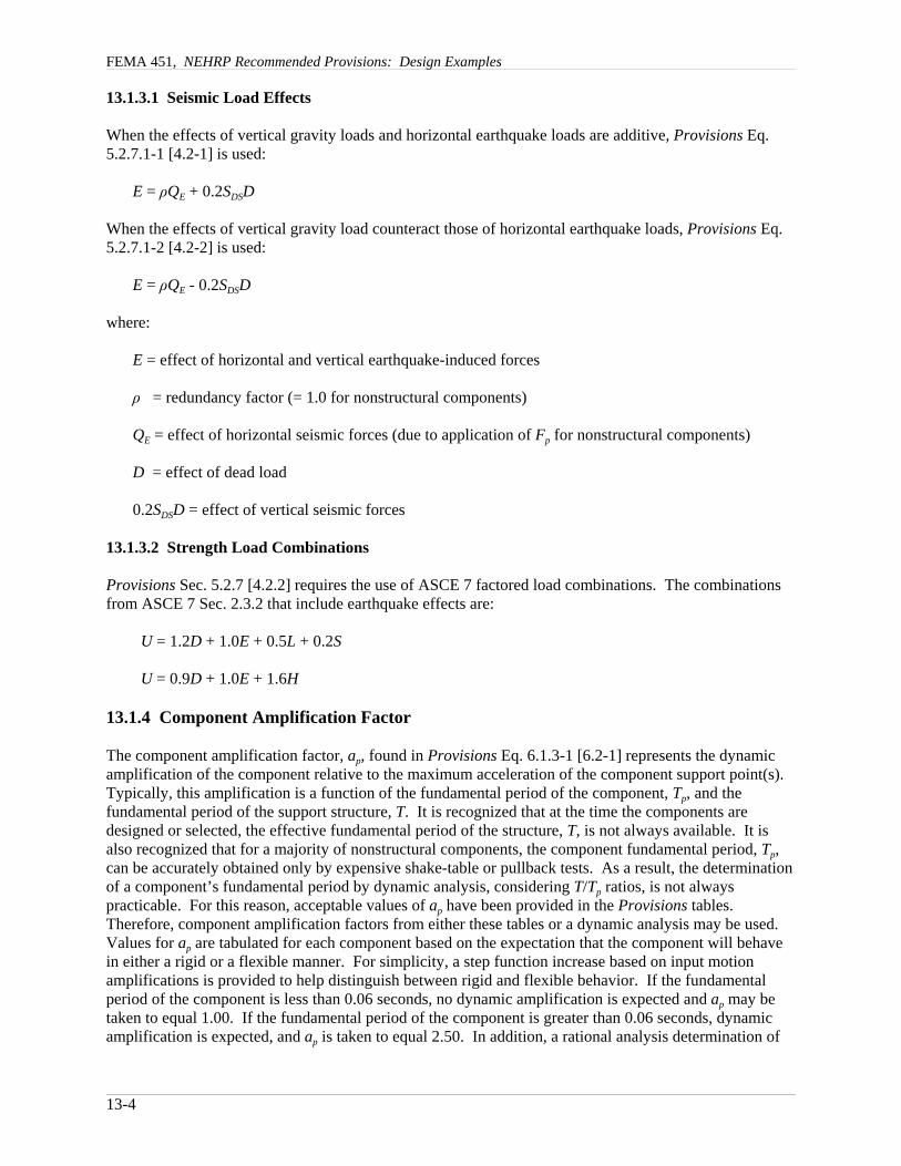
13.1.9 Accommodation of Seismic Relative Displacements
The Provisions requires that seismic relative displacements, Dp, be determined in accordance with severalequations. For two connection points on Structure A (or on the same structural system), one at Level xand the other at Level y, Dp is determined from Provisions Eq. 6.1.4-1 [6.2-5] as:
p xA yAD δ δ= −
Because the computed displacements are frequently not available to the designer of nonstructuralcomponents, one may use the maximum permissible structural displacements per Provisions Eq. 6.1.4-2[6.2-6]:
FEMA 451, NEHRP Recommended Provisions: Design Examples
13-6
( )max
aAp
sxD X Y
h∆
= −
For two connection points on Structures A and B (or on two separate structural systems), one at Level x,and the other at Level y, DP and DPmax are determined from Provisions Eq. 6.1.4-3 [6.2-7] and 6.1.4-4[6.2-8], respectively, as:
p xA yBD δ δ= +
max
aA aBp
sx sx
X YDh h∆ ∆
= +
where:
Dp = seismic relative displacement that the component must be designed to accommodate
δxA = deflection of building Level x of Structure A, determined by an elastic analysis as definedin Provisions Sec. 5.4.6.1 or 5.5.5 [5.2.6, 5.3.5, or 5.4.3] and multiplied by the Cd factor
δyA = deflection of building Level y of Structure A, determined in the same fashion as δxA
X = height of upper support attachment at Level x as measured from the base
Y = height of lower support attachment at Level y as measured from the base
∆aA = allowable story drift for Structure A as defined in Provisions Table 5.2.8 [4.5-1]
hsx = story height used in the definition of the allowable drift, ∆a, in Provisions Table 5.2.8[4.5-1]
δyB = deflection of building Level y of Structure B, determined in the same fashion as δxA
∆aB = allowable story drift for Structure B as defined in Provisions Table 5.2.8 [4.5-1]
The effects of seismic relative displacements must be considered in combination with displacementscaused by other loads as appropriate. Specific methods for evaluating seismic relative displacementeffects of components and associated acceptance criteria are not specified in the Provisions. However,the intention is to satisfy the purpose of the Provisions. Therefore, for nonessential facilities,nonstructural components can experience serious damage during the design level earthquake providedthey do not constitute a serious life safety hazard. For essential facilities, nonstructural components canexperience some damage or inelastic deformation during the design level earthquake provided they do notsignificantly impair the function of the facility.
13.1.10 Component Anchorage Factors and Acceptance Criteria
Design seismic forces in the connected parts, Fp, are prescribed in Provisions Sec. 6.1.3 [6.2.6].
When component anchorage is provided by expansion anchors or shallow anchors, a value of Rp = 1.5 is used. Shallow anchors are defined as those with embedment length-to-diameter ratios of less than 8.Anchors embedded in concrete or masonry are proportioned to carry the least of the following:
1. The design strength of the connected part

Chapter 13, Nonstructural Components
13-7
2. 1.3 times the prescribed seismic design force or3. The maximum force that can be transferred to the connected part by the component structural system
Determination of design seismic forces in anchors must consider installation eccentricities, prying effects,multiple anchor effects, and the stiffness of the connected system.
Use of powder-driven fasteners is not permitted for seismic design tension forces in Seismic DesignCategories D, E, and F unless approved for such loading.
[In the 2003 Provisions reference is made to “power-actuated” fasteners so as to cover a broader range offastener types than is implied by “powder-driven.”]
The design strength of anchors in concrete is determined in accordance with, Provisions Chapter 9, whichis basically the same as IBC Sec. 1913, and has been updated somewhat in Appendix D of ACI 318-2002. (These rules for anchors in concrete will probably be deleted from the next edition of the Provisions infavor of a reference to ACI 318.)
[The 2003 Provisions refer to Appendix D of ACI 318-02 rather than providing specific, detailedrequirements.]
13.1.11 Construction Documents
Construction documents must be prepared by a registered design professional and must include sufficientdetail for use by the owner, building officials, contractors, and special inspectors; Provisions Table 6.1.7[6.2-1] includes specific requirements.
13.2 ARCHITECTURAL CONCRETE WALL PANEL
13.2.1 Example Description
In this example, the architectural components are a 4.5-in.-thick precast normal weight concrete spandrelpanel and a column cover supported by the structural steel frame of a five-story building as shown inFigures 13.2-1 and 13.2-2.
FEMA 451, NEHRP Recommended Provisions: Design Examples
13-8
5 at
13'
-6"
= 67
'-6"
24'-0"
Structuralsteel frame
Typical windowframe system
Spandrel panelunder consideration
Column coverunder consideration
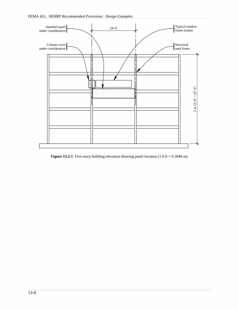
Figure 13.2-1 Five-story building elevation showing panel location (1.0 ft = 0.3048 m)
Chapter 13, Nonstructural Components
13-9
13'-6
" sto
ry h
eigh
t
T.O.S
T.O.S
24'-0"
6'-6
" pa
nel
7'-0
" co
lum
n co
ver
3 '-0"
Spandrel panelunder consideration
Typical windowframe system
Column coverunder consideration
~
~
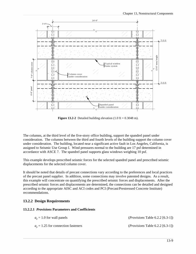
Figure 13.2-2 Detailed building elevation (1.0 ft = 0.3048 m).
The columns, at the third level of the five-story office building, support the spandrel panel underconsideration. The columns between the third and fourth levels of the building support the column coverunder consideration. The building, located near a significant active fault in Los Angeles, California, isassigned to Seismic Use Group I. Wind pressures normal to the building are 17 psf determined inaccordance with ASCE 7. The spandrel panel supports glass windows weighing 10 psf.
This example develops prescribed seismic forces for the selected spandrel panel and prescribed seismicdisplacements for the selected column cover.
It should be noted that details of precast connections vary according to the preferences and local practicesof the precast panel supplier. In addition, some connections may involve patented designs. As a result,this example will concentrate on quantifying the prescribed seismic forces and displacements. After theprescribed seismic forces and displacements are determined, the connections can be detailed and designedaccording to the appropriate AISC and ACI codes and PCI (Precast/Prestressed Concrete Institute)recommendations.
13.2.2 Design Requirements
13.2.2.1 Provisions Parameters and Coefficients
ap = 1.0 for wall panels (Provisions Table 6.2.2 [6.3-1])
ap = 1.25 for connection fasteners (Provisions Table 6.2.2 [6.3-1])
FEMA 451, NEHRP Recommended Provisions: Design Examples
13-10
SDS = 1.487 (Design Values CD-ROM for the selected location and site class)
[The 2003 Provisions have adopted the 2002 USGS probabilistic seismic hazard maps, and the maps havebeen added to the body of the 2003 Provisions as figures in Chapter 3 (instead of the previously usedseparate map package). The CD-ROM also has been updated.]
Seismic Design Category = D (Provisions Table 4.2.1a [1.4-1] for S1 < 0.75)
[In the footnote to 2003 Provisions Table 1.4-1, the value of S1 used to trigger assignment to SeismicDesign Category E or F was changed from 0.75 to 0.6.]
Spandrel Panel Wp = (150 lb/ft3)(24 ft)(6.5 ft)(0.375 ft) = 8775 lb
Glass Wp = (10 lb/ft2)(21 ft)(7 ft) = 1470 lb (supported by spandrel panel)
Column Cover Wp = (150 lb/ft3)(3 ft)(7 ft)(0.375 ft) = 1181 lb
Rp = 2.5 for wall panels (Provisions Table 6.3.2 [6.3-1])
Rp = 1.0 for connection fasteners ((Provisions Sec. 6.1.6.1 [6.2.8.1])
[In the 2003 Provisions component anchorage is designed using Rp = 1.5 unless specific ductility orprequalification requirements are satisfied.]
Ip = 1.0 (Provisions Sec. 6.1.5 [6.2.2])
(at third floor)40.5 ft 0.667.5 ft
zh= =
ρ = 1.0 (Provisions Sec. 6.1.3)
[The 2003 Provisions indicate that the redundancy factor does not apply to the design of nonstructuralcomponents. Although the effect is similar to stating that ρ = 1, there is a real difference since loadeffects for such components and their supports and attachments are now defined in Chapter 6 rather thanby reference to Chapter 4.]
13.2.2.2 Performance Criteria
Component failure should not cause failure of an essential architectural, mechanical, or electricalcomponent (Provisions Sec. 6.1 [6.2.3]).
Component seismic attachments must be bolted, welded, or otherwise positively fastened withoutconsidering the frictional resistance produced by the effects of gravity (Provisions Sec. 6.1.2 [6.2.5]).
The effects of seismic relative displacements must be considered in combination with displacementscaused by other loads as appropriate (Provisions Sec. 6.1.4 [6.2.7]).
Exterior nonstructural wall panels that are attached to or enclose the structure shall be designed to resistthe forces in accordance with Provisions Eq. 6.1.3-1 or 6.1.3-2 [6.2.6] and must be able to accommodatemovements of the structure resulting from response to the design basis ground motion, Dp, or temperaturechanges (Provisions Sec. 6.2.4 [6.3.2]).

Chapter 13, Nonstructural Components
13-11
A
A 1
A
A 1
B
B
3rd Story beam
6'-6
"pa
nel
7'-0
"
colu
mn
cove
r /w
indo
w fr
ame
24 '-0"
Panel C .G .
Figure 13.2-3 Spandrel panel connection layout from interior (1.0 ft = 0.3048 m).
13.2.3 Spandrel Panel
13.2.3.1 Connection Details
Figure 13.2-3 shows the types and locations of connections that support one spandrel panel.
The connection system must resist the weight of the panel and supported construction including theeccentricity between that load and the supports as well as inertial forces generated by response to theseismic motions in all three dimensions. Furthermore, the connection system must not create undueinteraction between the structural frame and the panel, such as restraint of the natural shrinkage of thepanel or the transfer of floor live load from the beam to the panel. The panels are usually very stiffcompared to the frame, and this requires careful release of potential constraints at connections. PCI’sArchitectural Precast Concrete (2nd Ed. 1989), provides an extended discussion of important designconcepts for such panels.
For this example, the basic gravity load, and vertical accelerations are resisted at Points A, whichprovides the recommended simple and statically determinant system for the main gravity weight. Theeccentricity of vertical loads is resisted by a force couple at the two pairs of A1 and A connections. Horizontal loads parallel to the panel are resisted by the A connections. Horizontal loads perpendicular tothe panel are resisted by all six connections. The A connections, therefore, restrain movement in threedimensions while the A1 and B connections restrain movement in only one dimension, perpendicular tothe panel. Connection components can be designed to resolve some eccentricities by bending of theelement; for example, the eccentricity of the horizontal in-plane force with the structural frame can beresisted by bending the A connection.
The practice of resisting the horizontal in-plane force at two points varies with seismic demand and localindustry practice. The option is to resist all of the in-plane horizontal force at one connection in order toavoid restraint of panel shrinkage. The choice made here depends on local experience indicating thatprecast panels of this length have been restrained at the two ends without undue shrinkage restraintproblems.
FEMA 451, NEHRP Recommended Provisions: Design Examples
13-12
The A and A1 connections are often designed to take the loads directly to the columns, particularly onsteel moment frames where attachments to the flexural hinging regions of beams are difficult toaccomplish. The lower B connection often require an intersecting beam to provide sufficient stiffness andstrength to resist the loads.
The column cover is supported both vertically and horizontally by the column, transfers no loads to thespandrel panel, and provides no support for the window frame.
The window frame is supported both vertically and horizontally along the length of the spandrel paneland transfers no loads to the column covers.
13.2.3.2 Prescribed Seismic Forces
Lateral forces on the wall panels and connection fasteners include seismic loads in accordance with theProvisions and wind loads in accordance with ASCE 7 as indicated in the problem statement. Windforces are not illustrated here.
13.2.3.2.1 Panels
D = Wp = 8775 lb + 1470 lb = 10245 lb (vertical gravity effect)
(Provisions Eq. 6.1.3-1 [6.2-1])( )( )( )
( ) ( )( )0.4 1.0 1.487 10245 lb1 2 0.6 5362 lb
2.51.0
pF = + =
(Provisions Eq. 6.1.3-2 [6.2-3])1.6(1.487)(1.0)(10245 lb) = 24375 lbmaxpF =
(Provisions Eq. 6.1.3-3 [6.2-4])0.3(1.487)(1.0)(10245 lb) = 4570 lbminpF =
[2003 Provisions Sec. 6.2.6 now treats load effects differently. The vertical forces that must beconsidered in design are indicated directly and the redundancy factor does not apply, so the following fivesteps would be cast differently; the result is the same.]
QE (due to application of Fp) = 5362 lb (Provisions Sec. 6.1.3)
ρQE = (1.0)(5362 lb) = 5362 lb (horizontal earthquake effect)
0.2SDSD = (0.2)(1.487)(10245 lb) = 3047 lb (vertical earthquake effect)
E = ρQE +0.2SDSD (Provisions Eq. 5.2.7.1-1 [4.2-1])
E = ρQE - 0.2SDSD (Provisions Eq. 5.2.7.1-2 [4.2-2])
13.2.3.2.2 Connection Fasteners
The Provisions specifies a reduced RP, and an increased aP for “Fasteners,” which is intended to preventpremature failure in those elements of connections that are inherently brittle, such as embedments thatdepend on concrete breakout strength, or are simply too small to adequately dissipate energy inelastically,such as welds or bolts. The net effect more than triples the design seismic force.
(Provisions Eq. 6.1.3-1 [6.2-1])( )( )( )
( ) ( )( )0.4 1.25 1.487 10245 lb1 2 0.6 16757 lb
1.01.0
pF = + =

Chapter 13, Nonstructural Components
13-13
(Provisions Eq. 6.1.3-2 [6.2-3])1.6(1.487)(1.0)(10245 lb) = 24375 lbmaxpF =
(Provisions Eq. 6.1.3-3 [6.2-4])0.3(1.487)(1.0)(10245 lb) = 4570 lbminpF =
[2003 Provisions Sec. 6.2.6 now treats load effects differently. The vertical forces that must beconsidered in design are indicated directly and the redundancy factor does not apply, so the following fivesteps would be cast differently; the result is the same.]
QE (due to application of Fp) = 16757 lb (Provisions Sec. 6.1.3)
ρQE = (1.0)(16757 lb) = 16757 lb (horizontal earthquake effect)
0.2SDSD = (0.2)(1.487)(10245 lb) = 3047 lb (vertical earthquake effect)
E = ρQE +0.2SDSD (Provisions Eq. 5.2.7.1-1 [4.2-1])
E = ρQE - 0.2SDSD (Provisions Eq. 5.2.7.1-2 [4.2-2]) 13.2.3.3 Proportioning and Design
13.2.3.3.1 Panels
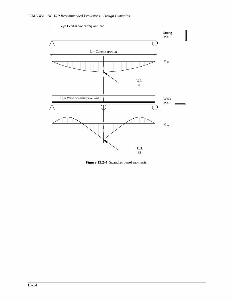
The wall panels should be designed for the following loads in accordance with ACI 318. The design ofthe reinforced concrete panel is standard and is not illustrated in this example. Spandrel panel momentsare shown in Figure 13.2-4. Reaction shears (Vu), forces (Hu), and moments (Mu) are calculated forapplicable strength load combinations.
FEMA 451, NEHRP Recommended Provisions: Design Examples
13-14
L = Column spacing
V = Dead and/or earthquake load
H = Wind or earthquake load
Strongaxis
M
Weakaxis
M
u
ux
uy
uV L8
32H Lu
u
Figure 13.2-4 Spandrel panel moments.
Chapter 13, Nonstructural Components
13-15
U = 1.4D
Vu = 1.4(10245 lb) = 14343 lb (vertical load downward)
(strong axis moment)( )( )14343 lb 24 ft
43029 ft-lb8uxM = =
U = 1.2D + 1.0E
(vertical load downward)1.2(10245 lb) 1.0(3047 lb) 15341 lbmaxuV = + =
(horizontal load parallel to panel)1.0(5362 lb) 5362 lbuH⇔ = =
(horizontal load perpendicular to panel)1.0(5362 lb) 5362 lbuH⊥ = =
(strong axis moment)( )( )15341 lb 24 ft46023 ft-lb
8maxuxM = =
(weak axis moment)( )( )5362 lb 24 ft
4022 ft-lb32uyM = =
U = 0.9D + 1.0E
(vertical load downward)0.9(10245 lb) 1.0(3047 lb) 6174 lbminuV = − =
(horizontal load parallel to panel)1.0(5362 lb) 5362 lbuH⇔ = =
(horizontal load perpendicular to panel)1.0(5362 lb) 5362 lbuH⊥ = =
(strong axis moment)( )( )6174 lb 24 ft18522 ft-lb
8minuxM = =
(weak axis moment)( )( )5362 lb 24 ft
4022 ft-lb32uyM = =
13.2.3.3.2 Connection Fasteners
The connection fasteners should be designed for the following loads in accordance with ACI 318-2002 (Appendix D) and the AISC specification. There are special reduction factors for anchorage in highseismic demand locations, and the parameters for this project would invoke those reduction factors. Thedesign of the connection fasteners is not illustrated in this example. Spandrel panel connection forces areshown in Figure 13.2-5. Reaction shears (Vu), forces (Hu), and moments (Mu) are calculated for applicablestrength load combinations.

FEMA 451, NEHRP Recommended Provisions: Design Examples
13-16
D = DeadE = EarthquakeW = WindR = Reaction
Panel C.G.
RA
RA1
RA
E, W
D
E
1'-6"
1'-4
"8"1'
-4"
Figure 13.2-5 Spandrel panel connection forces.
U = 1.4D
(vertical load downward at Point A and A1)( )1.4 10245 lb
7172 lb2uAV = =
MuA = (7172 lb)(1.5 ft) = 10758 ft-lb (moment resisted by paired Points A and A1)
Horizontal couple from moment at A and A1 = 10758 / 1.33 = 8071 lb
U = 1.2D + 1.0E
(vertical load downward at Point A)1.2(10245 lb) 1.0(3047 lb) 7671 lb2maxuAV +
= =
(horizontal load perpendicular to panel at Points A and A1)31.0(16757 lb) 3142 lb16uAH⊥ = =
HAin = (7671 lb)(1.5 ft) / (1.33 ft) + (3142 lb)(2.0 ft) / (1.33 ft) = 13366 lb (inward force at Point A)
HA1out = (7671 lb)(1.5 ft) / (1.33 ft) + (3142 lb)(0.67) / (1.33 ft) = 10222 lb(outward force at Point A1)
(horizontal load parallel to panel at Point A)1.0(16757 lb) 8378 lb2uAH⇔ = =
Mu2A = (8378 lb)(1.5 ft) = 12568 ft-lb (flexural moment at Point A)
(horizontal load perpendicular to panel at Points B and B1)51.0(16757 lb) 10473 lb8uBH⊥ = =

Chapter 13, Nonstructural Components
13-17
1'-3
"6'
-0"
1'-6"
24'-0"
Cover C.G.
C E
EDcolu
mn
cove
r /w
indo
w fr
ame
7'-0
"6'
-6"
pane
l
Figure 13.2-6 Column cover connection layout (1.0 ft = 0.3048 m).
HB = (10743 lb)(2.0 ft) / (1.33 ft) = 15714 lb (inward or outward force at B)
HB1 = (10473 lb)(0.67 ft) / (1.33 ft) = 5237 lb (inward or outward force at B1)
U = 0.9D + 1.0E
(vertical load downward at Point A)0.9(10245 lb) 1.0(3047 lb) 3086 lb2minuAV −
= =
Horizontal forces are the same as combination 1.2 D + 1.0 E. No uplift occurs; the net reaction at A isdownward. Maximum forces are controlled by prior combination. It is important to realize that inwardand outward acting horizontal forces generate different demands when the connections are eccentric to thecenter of mass as it is in this example. Only the maximum reactions are computed above.
13.2.3.4 Prescribed Seismic Displacements
Prescribed seismic displacements are not applicable to the building panel because all connections areessentially at the same elevation.
13.2.4 Column Cover
13.2.4.1 Connection Details
Figure 13.2-6 shows the key to the types of forces resisted at each column cover connection.
Vertical loads, horizontal loads parallel to the panel, and horizontal loads perpendicular to the panel areresisted at Point C. The eccentricity of vertical loads is resisted by a force couple at Points C and D. Thehorizontal load parallel to the panel eccentricity between the panel and the support is resisted in flexure ofthe connection. The connection is designed to take the loads directly to the columns.
Horizontal loads parallel to the panel and horizontal loads perpendicular to the panel are resisted at PointD. The vertical load eccentricity between the panel and the support is resisted by a force couple of Points
FEMA 451, NEHRP Recommended Provisions: Design Examples
13-18
C and D. The eccentricity of horizontal loads parallel to the panel is resisted by flexure at the connection. The connection must not restrict vertical movement of the panel due to thermal effects or seismic input. The connection is designed to take the loads directly to the columns.
Horizontal loads perpendicular to the panel are resisted at Points E. The connection is designed to takethe loads directly to the columns.
There is no load eccentricity associated with the horizontal loads perpendicular to the panel.
In this example, all connections are made to the sides of the column because there usually is not enoughroom between the outside face of the column and the inside face of the cover to allow a feasibleload-carrying connection.
13.2.4.2 Prescribed Seismic Forces
Calculation of prescribed seismic forces for the column cover are not shown in this example. Theyshould be determined in the same manner as illustrated for the spandrel panels.
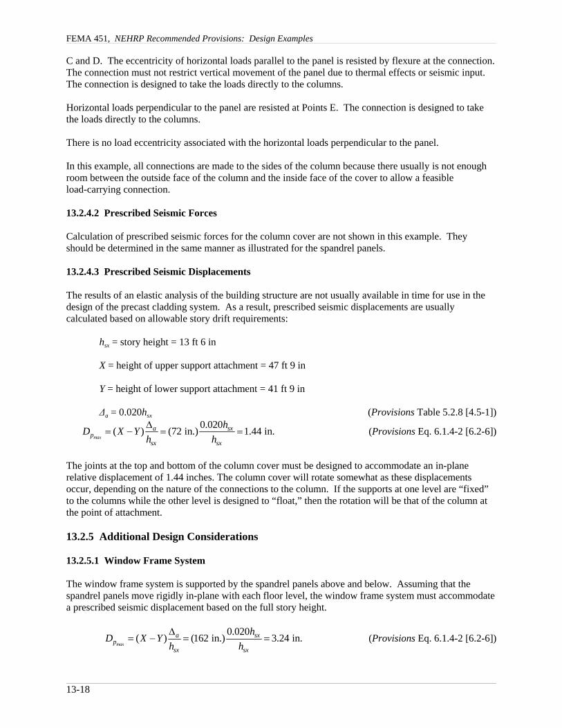
13.2.4.3 Prescribed Seismic Displacements
The results of an elastic analysis of the building structure are not usually available in time for use in thedesign of the precast cladding system. As a result, prescribed seismic displacements are usuallycalculated based on allowable story drift requirements:
hsx = story height = 13 ft 6 in
X = height of upper support attachment = 47 ft 9 in
Y = height of lower support attachment = 41 ft 9 in
∆a = 0.020hsx (Provisions Table 5.2.8 [4.5-1])
(Provisions Eq. 6.1.4-2 [6.2-6])0.020( ) (72 in.) 1.44 in.
max
a sxp
sx sx
hD X Yh h∆
= − = =
The joints at the top and bottom of the column cover must be designed to accommodate an in-planerelative displacement of 1.44 inches. The column cover will rotate somewhat as these displacementsoccur, depending on the nature of the connections to the column. If the supports at one level are “fixed”to the columns while the other level is designed to “float,” then the rotation will be that of the column atthe point of attachment.
13.2.5 Additional Design Considerations
13.2.5.1 Window Frame System
The window frame system is supported by the spandrel panels above and below. Assuming that thespandrel panels move rigidly in-plane with each floor level, the window frame system must accommodatea prescribed seismic displacement based on the full story height.
(Provisions Eq. 6.1.4-2 [6.2-6])0.020( ) (162 in.) 3.24 in.
max
a sxp
sx sx
hD X Yh h∆
= − = =

Chapter 13, Nonstructural Components
13-19
The window frame system must be designed to accommodate an in-plane relative displacement of 3.24 in.between the supports. This is normally accommodated by a clearance between the glass and the frame. Provisions Sec. 6.2.10.1 [6.3.7], prescribes a method of checking such a clearance. It requires that theclearance be large enough so that the glass panel will not fall out of the frame unless the relative seismicdisplacement at the top and bottom of the panel exceeds 125 percent of the value predicted amplified bythe building importance factor. If hp and bp are the respective height and width of individual panes and ifthe horizontal and vertical clearances are designated c1 and c2, respectively, then the following expressionapplies:
21
12 1 1.25p
clear pp
h cD c D
b c⎛ ⎞
= + ≥⎜ ⎟⎜ ⎟⎝ ⎠
For hp = 7 ft, bp = 5 ft, and Dp = 3.24 in., and setting c1 = c2, the required clearance is 0.84 in.
13.2.5.2 Building Corners
Some thought needs to be given to seismic behavior at external building corners. The preferred approachis to detail the corners with two separate panel pieces, mitered at a 45 degree angle, with high gradesealant between the sections. An alternative choice of detailing L-shaped corner pieces, would introducemore seismic mass and load eccentricity into connections on both sides of the corner column.
13.2.5.3 Dimensional Coordination
It is important to coordinate dimensions with the architect and structural engineer. Precast concretepanels must be located a sufficient distance from the building structural frame to allow room for thedesign of efficient load transfer connection pieces. However, distances must not be so large as tounnecessarily increase the load eccentricities between the panels and the frame.
13.3 HVAC FAN UNIT SUPPORT
13.3.1 Example Description
In this example, the mechanical component is a 4-ft-high, 5-ft-wide, 8-ft-long, 3000-lb HVAC fan unitthat is supported on the two long sides near each corner (Figure 13.3-1). The component is located at theroof level of a five-story office building, near a significant active fault in Los Angeles, California. Thebuilding is assigned to Seismic Use Group I. Two methods of attaching the component to the 4,000 psi,normal-weight roof slab, are considered as follows:
1. Direct attachment to the structure with 36 ksi, carbon steel, cast-in-place anchors and2. Support on vibration isolation springs, that are attached to the slab with 36 ksi carbon steel
post-installed expansion anchors.

FEMA 451, NEHRP Recommended Provisions: Design Examples
13-20
Concrete Concrete
b = 5'-6"a = 7'-0"
4'-0
"
2'-0
"
Center-of-mass
Elevation
Plan8'-0"
5'-0
"
Attachment location (typical).Direct attachment shownHVAC fan unit
W = 3,000 lbs
Elevation
Figure 13.3-1 Air handling fan unit (1.0 ft = 0.3048 m, 1.0 lb = 4.45 N).
13.3.2 Design Requirements
13.3.2.1 Provisions Parameters and Coefficients
ap = 1.0 for direct attachment (Provisions Table 6.3.2 [6.4-1])
ap = 2.5 for vibration isolated (Provisions Table 6.3.2 [6.4-1])
SDS = 1.487 (Design Values CD-ROM)
[The 2003 Provisions have adopted the 2002 USGS probabilistic seismic hazard maps, and the maps havebeen added to the body of the 2003 Provisions as figures in Chapter 3 (instead of the previously usedseparate map package).]
Seismic Design Category = D (Provisions Table 4.2.1a [14.4-1])
Wp = 3000 lb (given)
Rp = 2.5 for HVAC system equipment (Provisions Table 6.3.2 [6.4-1])
Rp = 1.5 for expansion anchors and shallow, cast-in-place anchors* ((Provisions Sec. 6.1.6.1 [6.2.8.1])
Shallow anchors are defined by Provisions Sec. 2.1 as anchors having embedment-to-diameter ratios of less than 8.

Chapter 13, Nonstructural Components
13-21
[In the 2003 Provisions component anchorage is treated differently. Rather than making distinctionsbased on an anchor being “shallow,” component anchorage is designed using Rp = 1.5 unless specificductility or prequalification requirements are satisfied.]
Ip = 1.0 (Provisions Sec. 6.1.5 [6.2.2])
z/h = 1.0 (for roof mounted equipment)
ρ = 1.0 (Provisions Sec. 6.1.3 [6.2.6])
[The 2003 Provisions indicate that the redundancy factor does not apply to the design of nonstructuralcomponents. Although the effect is similar to stating that ρ = 1, there is a real difference since loadeffects for such components and their supports and attachments are now defined in Chapter 6 rather thanby reference to Chapter 4.]
13.3.2.2 Performance Criteria
Component failure should not cause failure of an essential architectural, mechanical, or electricalcomponent (Provisions Sec. 6.1 [6.2.3]).
Component seismic attachments must be bolted, welded, or otherwise positively fastened withoutconsideration of frictional resistance produced by the effects of gravity (Provisions Sec. 6.1.2 [6.2.5]).
Anchors embedded in concrete or masonry must be proportioned to carry the least of: (a) the designstrength of the connected part, (b) 1.3 times the force in the connected part due to the prescribed forces, or(c) the maximum force that can be transferred to the connected part by the component structural system(Provisions Sec. 6.1.6.2 [6.2.8.2]).
Attachments and supports transferring seismic loads must be constructed of materials suitable for theapplication and must be designed and constructed in accordance with a nationally recognized structuralstandard (Provisions Sec. 6.3.13.2.a [6.4.4, item 6]).
Components mounted on vibration isolation systems must have a bumper restraint or snubber in eachhorizontal direction. Vertical restraints must be provided where required to resist overturning. Isolatorhousings and restraints must also be constructed of ductile materials. A viscoelastic pad, or similarmaterial of appropriate thickness, must be used between the bumper and equipment item to limit theimpact load (Provisions Sec. 6.3.13.2.e). Such components must also resist an amplified design force.
13.3.3 Direct Attachment to Structure
This section illustrates design for cast-in-place concrete anchors with embedment-length-to-diametersratios of 8 or greater; thus, the use of Rp = 2.5 is permitted. [In 2003 Provisions Sec. 6.2.8.1, the value ofRp used in designing component anchorage is no longer based on the embedment depth-to-diameter ratio. Instead Rp = 1.5 unless specific ductility or prequalification requirements are satisfied.]
13.3.3.1 Prescribed Seismic Forces
See Figure 13.3-2 for freebody diagram for seismic force analysis.

FEMA 451, NEHRP Recommended Provisions: Design Examples
13-22
(Provisions Eq. 6.1.3-1 [6.2-1])( )( )( )( ) ( )( )0.4 1.0 1.487 3000 lb
1 2 1 2141 lb2.5
1.0pF = + =
(Provisions Eq. 6.1.3-2 [6.2-3])1.6(1.487)(1.0)(3000 lb) 7138 lbmaxpF = =
(Provisions Eq. 6.1.3-3 [6.2-4])0.3(1.487)(1.0)(3000 lb) 1338 lbminpF = =
[2003 Provisions Sec. 6.2.6 now treats load effects differently. The vertical forces that must beconsidered in design are indicated directly and the redundancy factor does not apply, so the following sixsteps would be cast differently; the result is the same.]
QE (due to application of Fp) = 2141 lb (Provisions Sec. 6.1.3)
ρQE = (1.0)(2141 lb) = 2141 lb (horizontal earthquake effect)
0.2SDSD = (0.2)(1.487)(3000 lb) = 892 lb (vertical earthquake effect)
D = Wp = 3000 lb (vertical gravity effect)
E = ρQE + 0.2SDSD (Provisions Eq. 5.2.7.1-1 [4.2-1])
E = ρQE - 0.2SDSD (Provisions Eq. 5.2.7.1-2 [4.2-2])
U = 1.2D + 1.0E + 0.5L + 0.2S
( )1.0 2141 lb535 lb/bolt
4 boltsuV = =
no tension( )( ) ( )( ) ( )( )
( )( )1.2 3000 lb 2.75 ft 1.0 2141 lb 2 ft 1.0 892 lb 2.75 ft
288 lb/bolt5.5 ft 2 boltsuT
− + += = −
U = 0.9D - (1.3W or 1.0E)
R
V V
T
D
QEρ
0.2S DDS
2'-0
"
5'-6"
u
u
u
u
Figure 13.3-2 Free-body diagram for seismic force analysis(1.0 ft = 0.348 m).

Chapter 13, Nonstructural Components
13-23
Component base
Tu
uV
Figure 13.3-3 Anchor for directattachment to structure.
( )1.0 2141 lb
535 lb/bolt4 boltsuV = =
no tension( )( ) ( )( ) ( )( )
( )( )0.9 3000 lb 2.75 ft 1.0 2141 lb 2 ft 1.0 892 lb 2.75 ft
63 lb/bolt5.5 ft 2 boltsuT
− + += = −
13.3.3.2 Proportioning and Design
See Figure 13.3-3 for anchor for direct attachment to structure.
Check one ¼-in.-diameter cast-in-place anchor embedded 2 in. into the concrete slab with no transversereinforcing engaging the anchor and extending through the failure surface. Although there is no requiredtension strength on these anchors, design strengths and tension/shear interaction acceptance relationshipsare calculated to demonstrate the use of the Provisions equations.
5.3.3.2.1 Design Tension Strength on Isolated Anchor in Slab, Away from Edge, Loaded Concentrically
[The 2003 Provisions refer to Appendix D of ACI 318-02 rather than providing specific, detailedrequirements. Note also that some of the resistance factors, φ, are different.]
Following Provisions Sec. 9.2, for a headed bolt or a rod with a nut at the bottom:
(not shallow, Rp = 2.5 is permitted)2 in. 8.0
0.25 in.Ld= =
[In 2003 Provisions selection of Rp is no longer based on the L/d ratio; see Sec. 6.2.8.1.]
Tension capacity of steel, φ = 0.80:
Ns = AseFy = (0.049 in.2)(36000 psi) = 1764 lb (Provisions Sec. 9.2.5.1.2 [ACI 318-02 Eq. D-3])
[In Appendix D of ACI 318-02 this capacity calculation is based on fut rather than Fy, since “the largemajority of anchor materials do not exhibit a well-defined yield point.”]
Tension capacity of concrete, φ = 0.70, with no eccentricity, no pullthrough, and no edge or group effect:
(Provisions Eq. 9.2.5.2.2-1 [ACI 318-02 Eq. D-7])1.5 1.524 4000 psi (8 ) 4293 lbc c efN k f h′= = =

FEMA 451, NEHRP Recommended Provisions: Design Examples
13-24
[In Appendix D of ACI 318-02 this item is defined as Nb rather than Nc.]
The steel controls but, with no tension demand, the point is moot.
5.3.3.2.2 Design Shear Strength on Isolated Anchor, Away from Edge
Shear capacity of steel, φ = 0.80:
Vs = AseFy = (0.049 in.2)(36000 psi) = 1764 lb (Provisions Eq. 9.2.6.1.2-1 [ACI 318-02 Eq. D-17)
[In Appendix D of ACI 318-02 this capacity calculation is based on fut rather than Fy, since “the largemajority of anchor materials do not exhibit a well-defined yield point.”]
Shear capacity of concrete, far from edge, limited to pryout, φ = 0.70:
Vcp = 2Nc = 2(4293) = 8493 lb (Provisions Eq. 9.2.6.3.1 [ACI 318-02 Eq. D-28)
The steel controls, with φVN = 0.8(1764) = 1411 lb
Per Provisions Sec. 6.1.6.2 [6.2.8.2], anchors embedded in concrete or masonry are to be proportioned tocarry at least 1.3 times the force in the connected part due to the prescribed forces. Thus, Vu = 1.3(535) =696 lb and the anchor is clearly adequate.
5.3.3.2.3 Combined Tension and Shear
The Provisions gives a new equation (Eq. 9.2.7.3 [ACI 318-02 Eq. D-29]) for the interaction of tensionand shear on an anchor or a group of anchors:
, which applies when either term exceeds 0.21.2u u
N N
N VN Vφ φ
+ ≤
5.3.3.2.3 Summary
At each corner of the component, provide one ¼-in.-diameter cast-in-place anchor embedded 2 in. intothe concrete slab. Transverse reinforcement engaging the anchor and extending through the failuresurface is not necessary.
13.3.4 Support on Vibration Isolation Springs
13.3.4.1 Prescribed Seismic Forces
Design forces for vibration isolation springs are determined by an analysis of earthquake forces applied ina diagonal horizontal direction as shown in Figure 13.3-4. Terminology and concept are taken fromASHRAE APP IP.
Angle of diagonal loading:
(ASHRAE APP IP. Eq. 17)-1tan ba
θ ⎛ ⎞= ⎜ ⎟⎝ ⎠
Tension per isolator:
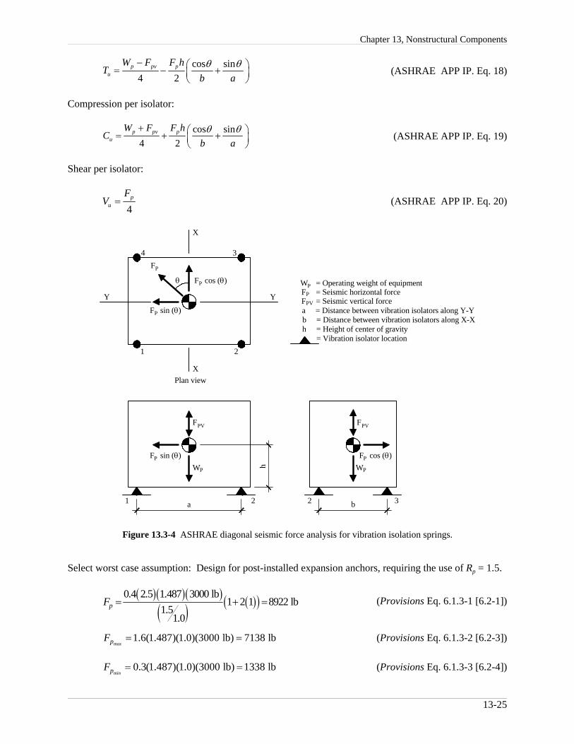
Chapter 13, Nonstructural Components
13-25
h
a1 2 2 3b
F sin (θ)P
WP
FPV PVF
PWPF cos (θ)
1 2
XPlan view
X
Y Y
PF sin (θ)
PF cos (θ)θ
FP
4 3
F = Seismic horizontal forcePPW = Operating weight of equipment
PVF = Seismic vertical forcea = Distance between vibration isolators along Y-Yb = Distance between vibration isolators along X-Xh = Height of center of gravity = Vibration isolator location
Figure 13.3-4 ASHRAE diagonal seismic force analysis for vibration isolation springs.
(ASHRAE APP IP. Eq. 18)cos sin
4 2p pv p
u
W F F hT
b aθ θ− ⎛ ⎞= − +⎜ ⎟
⎝ ⎠
Compression per isolator:
(ASHRAE APP IP. Eq. 19)cos sin
4 2p pv p
u
W F F hC
b aθ θ+ ⎛ ⎞= + +⎜ ⎟
⎝ ⎠
Shear per isolator:
(ASHRAE APP IP. Eq. 20)4
pu
FV =
Select worst case assumption: Design for post-installed expansion anchors, requiring the use of Rp = 1.5.
(Provisions Eq. 6.1.3-1 [6.2-1])( )( )( )( ) ( )( )0.4 2.5 1.487 3000 lb
1 2 1 8922 lb1.5
1.0pF = + =
(Provisions Eq. 6.1.3-2 [6.2-3])1.6(1.487)(1.0)(3000 lb) 7138 lbmaxpF = =
(Provisions Eq. 6.1.3-3 [6.2-4])0.3(1.487)(1.0)(3000 lb) 1338 lbminpF = =
FEMA 451, NEHRP Recommended Provisions: Design Examples
13-26
Components mounted on vibration isolation systems shall have a bumper restraint or snubber in eachhorizontal direction. Per Provisions Table 6.3.2 [6.4-1], Footnote B, the design force shall be taken as2Fp.
[2003 Provisions Sec. 6.2.6 now treats load effects differently. The vertical forces that must beconsidered in design are indicated directly and the redundancy factor does not apply, so the followingsteps would be cast differently; the result is the same.]
QE = Fp = 2(7138 lb) = 14276 lb (Provisions Sec. 6.1.3)
ρQE = (1.0)(14276 lb) = 14276 lb (horizontal earthquake effect)
Fpv(ASHRAE) = 0.2SDSD = (0.2)(1.487)(3000 lb) = 892 lb (vertical earthquake effect)
D = Wp = 3000 lb (vertical gravity effect)
E = ρQE + 0.2SDSD (Eq. 5.2.7.1-1 [4.2-1])
E = ρQE - 0.2SDSD (Eq. 5.2.7.1-2 [4.2-2])
U = 1.2D + 1.0E + 0.5L + 0.2S
1 o7 fttan 51.85.5 ft
θ − ⎛ ⎞= =⎜ ⎟⎝ ⎠
1.2(3000 lb) (892 lb) (14276 lb)(2 ft) cos(51.8 ) sin(51.8 ) 2624 lb4 2 7 ft 5.5 ftuT − ° °⎛ ⎞= − + = −⎜ ⎟
⎝ ⎠
1.2(3000 lb)+(892 lb) (14276 lb)(2 ft) cos(51.8 ) sin(51.8 ) 4424 lb4 2 7 ft 5.5 ftuC ° °⎛ ⎞= + + =⎜ ⎟
⎝ ⎠
14276 lb 3569 lb4uV = =
U = 0.9D + 1.0E
1 o7 fttan 51.85.5 ft
θ − ⎛ ⎞= =⎜ ⎟⎝ ⎠
0.9(3000 lb) (892 lb) (14276 lb)(2 ft) cos(51.8 ) sin(51.8 ) 2849 lb4 2 7 ft 5.5 ftuT − ° °⎛ ⎞= − + = −⎜ ⎟
⎝ ⎠
0.9(3000 lb) (892 lb) (14276 lb)(2 ft) cos(51.8 ) sin(51.8 ) 4199 lb4 2 7 ft 5.5 ftuC + ° °⎛ ⎞= + + =⎜ ⎟
⎝ ⎠
14276 lb 3569 lb4uV = =
13.3.4.2 Proportioning and Details

Chapter 13, Nonstructural Components
13-27
T W = 4"
V
"O"
T
V
H =
5"
Vibration isolatorw/ seismic housing
Equipment frame
u
u
b
b
Figure 13.3-5 Anchor and snubber loads forsupport on vibration isolation springs (1.0 in. = 25.4mm).
Anchor and snubber loads for support on vibration isolation springs are shown in Figure 13.3-5.
Check vibration isolation system within housing anchored with two 1-in.-diameter post-installedexpansion anchors embedded 9 inches into the concrete.
The Provisions does not provide a basis for determining the design strength of post-installed expansionanchors. Although manufacturers provide ultimate strength shear and tension loads for their products, theProvisions does not provide resistance or quality values, φ, to allow determination of design shear andtension strengths. The 2002 edition of ACI 318 contains provisions for post-installed anchors whichdepend on anchor testing per the ACI 355.2-01 testing standard. Prior to the adoption of this method, thebest course available was to use allowable stress loads published in evaluation reports prepared by modelbuilding code agencies. These allowable stress loads were then multiplied by 1.4 to convert to designstrengths. This technique will be illustrated in the following.
[The 2003 Provisions refer to Appendix D of ACI 318-02.]
Allowable stress combinations are included in the 2000 IBC. The 1.4 strength conversion factor isunnecessary when using allowable stress loads published in evaluation reports prepared by modelbuilding code agencies.
13.3.4.2.1 Design Tension Strength on Isolated Anchor in Slab, Away from Edge
Allowable stress tension values are obtained from ICBO Evaluation Services, Inc., ER-4627 for HiltiKwik Bolt II concrete anchors. Similar certified allowable values are expected with anchors from othermanufacturers.
anchor diameter = 1 in.
anchor depth = 9 in.
fc' = 4000 psi

FEMA 451, NEHRP Recommended Provisions: Design Examples
13-28
with special inspection
Tallow = 8800 lb
Ps = φPc = 1.4(8800 lb) = 12320 lb
13.3.4.2.2 Design Shear Strength on Isolated Anchor in Slab, Away from Edge
Allowable stress shear values are obtained from ICBO Evaluation Services, Inc., ER-4627 for Hilti KwikBolt II concrete anchors. Similar certified allowable values are expected with anchors from othermanufacturers.
anchor diameter = 1 in.
anchor depth = 9 in.
fc' = 4000 psi
Vallow = 8055 lb
Vs = φVc = 1.4(8055 lb) = 11277 lb
13.3.4.2.3 Combined Tension and Shear
Per Provisions Sec. 6.1.6.2 [6.2.8.2], anchors embedded in concrete or masonry shall be proportioned tocarry at least 1.3 times the force in the connected part due to the prescribed forces.
In the Provisions and in the 2000 IBC, the factor of 2.0 is reduced to 1.3. This will greatly reduce theprescribed seismic forces.
Interaction relationships for combined shear and tension loads are obtained from ICBO EvaluationServices, Inc. ER-4627 for Hilti Kwik Bolt II concrete anchors. Similar results are expected using otheranchors.
As stated in ICBO ES evaluation report:
5 53 3
1s s
t t
P VP V
⎛ ⎞ ⎛ ⎞+ ≤⎜ ⎟ ⎜ ⎟
⎝ ⎠ ⎝ ⎠
Using Provisions terminology:
5 53 3
1b b
c c
T VP Vφ φ
⎛ ⎞ ⎛ ⎞+ ≤⎜ ⎟ ⎜ ⎟
⎝ ⎠ ⎝ ⎠
OK5 5
3 32 4462 lb 2 1785 lb 0.68 0.13 0.81 111277 lb 12075 lb× ×⎛ ⎞ ⎛ ⎞+ = + = <⎜ ⎟ ⎜ ⎟
⎝ ⎠ ⎝ ⎠
13.3.4.2.4 Summary
Chapter 13, Nonstructural Components
13-29
Gap GapEquipment
frameImpactmaterial
Steel bushingbolted or weldedto equipment frame
Figure 13.3-6 Lateral restraint required to resist seismic forces.
At each corner of the HVAC fan unit, provide a vibration isolation system within a housing anchoredwith two 1-in.-diameter post-installed expansion anchors embedded 9 in. into the concrete slab. Specialinspection is required. A raised concrete pad is probably required to allow proper embedment of thepost-installed expansion anchors.
Other post-installed anchors, such as chemical (adhesive) or undercut post-installed anchors also could beinvestigated. These anchors may require more involved installation procedures, but they may allow theuse of Rp = 2.5 if they have an embedment depth-to-diameter ratio of at least 8 (i.e., are not shallowanchors). The higher Rp value will result in much smaller prescribed seismic forces and, therefore, amuch reduced embedment depth.
[Again note that in 2003 Provisions selection of Rp is no longer based on the L/d ratio; see Sec. 6.2.8.1.]
13.3.5 Additional Considerations for Support on Vibration Isolators
Vibration isolation springs are provided for equipment to prevent vibration from being transmitted to thebuilding structure. However, they provide virtually no resistance to horizontal seismic forces. In suchcases, some type of restraint is required to resist the seismic forces. Figure 13.3-6 illustrates one conceptwhere a bolt attached to the equipment base is allowed to slide a controlled distance (gap) in eitherdirection along its longitudinal axis before it contacts resilient impact material.
Design of restraints for vibration-isolated equipment varies for different applications and for differentmanufacturers. In most cases, restraint design incorporates all directional capability with an air gap, asoft impact material, and a ductile restraint or housing.
Restraints should have all-directional restraint capability to resist both horizontal and vertical motion. Vibration isolators have little or no resistance to overturning forces. Therefore, if there is a difference inheight between the equipment center of gravity and the support points of the springs, rocking is inevitableand vertical restraint is required.
FEMA 451, NEHRP Recommended Provisions: Design Examples
13-30
An air gap between the restraint device and the equipment prevents vibration from transmitting to thestructure during normal operation of the equipment. Air gaps are generally no greater than ¼ in. Dynamic tests indicate a significant increase in acceleration for air gaps larger than ¼ in.
A soft impact material often an elastomer such as bridge bearing neoprene reduces accelerations andimpact loads by preventing steel-to-steel contact. The thickness of the elastomer can significantly reduceaccelerations to both the equipment and the restraint device and should be specifically addressed for lifesafety applications.
A ductile restraint or housing is critical to prevent catastrophic failure. Unfortunately, housed isolatorsmade of brittle materials such as cast iron often are assumed to be capable of resisting seismic loads andcontinue to be installed in seismic zones.
Overturning calculations for vibration- isolated equipment must consider a worst case scenario asillustrated in Guide Sec. 13.3.4.1. However, important variations in calculation procedures merit furtherdiscussion. For equipment that is usually directly attached to the structure, or mounted on housedvibration isolators, the weight can be used as a restoring force since the equipment will not transfer atension load to the anchors until the entire equipment weight is overcome at any corner. For equipmentinstalled on any other vibration isolated system (such as the separate spring and snubber arrangementshown in Figure 13.3-5), the weight cannot be used as a restoring force in the overturning calculations.
As the foregoing illustrates, design of restraints for resiliently mounted equipment is a specialized topic. The Provisions sets out only a few of the governing criteria. Some suppliers of vibration isolators in thehighest seismic zones are familiar with the appropriate criteria and procedures. Consultation with thesesuppliers may be beneficial.
13.4 ANALYSIS OF PIPING SYSTEMS
13.4.1 ASME Code Allowable Stress Approach
Piping systems are typically designed to satisfy national standards such as ASME B31.1. Piping requiredto be designed to other ASME piping codes use similar approaches with similar definition of terms.
13.4.1.1 Earthquake Design Requirements
ASME B31.1 Sec. 101.5.3 requires that the effects of earthquakes, where applicable, be considered in thedesign of piping, piping supports, and restraints using data for the site as a guide in assessing the forcesinvolved. However, earthquakes need not be considered as acting concurrently with wind.
13.4.1.2 Stresses Due to Sustained Loads
The effects of pressure, weight, and other sustained loads must meet the requirements of ASME B31.1Eq. 11A:
0.75 1.04
o AL h
n
PD iMS St Z
= + ≤
where:
SL = sum of the longitudinal stresses due to pressure, weight, and other sustained loads
P = internal design pressure, psig
Chapter 13, Nonstructural Components
13-31
Do = outside diameter of pipe, in.
tn = nominal pipe wall thickness, in.
i = stress intensification factor from ASME Piping Code Appendix D, unitless = 1.0 for straight pipe $ 1.0 for fittings and connections
MA = resultant moment loading on cross section due to weight and other sustained loads, in.-lb
Z = section modulus, in.3
Sh = basic material allowable stress at maximum (hot) temperature from ASME Piping Code Appendix A
For example, ASTM A53 seamless pipe and tube, Grade B: Sh = 15.0 ksi for -20 to 650 degrees F.
13.4.1.3 Stresses Due to Occasional Loads
The effects of pressure, weight, and other sustained loads, and occasional loads including earthquakemust meet the requirements of ASME B31.1 Eq. 12A:
0.75 0.754
o A Bh
n
PD iM iM kSt Z Z
+ + ≤
where:
MB = resultant moment loading on cross-section due to occasional loads, such as from thrust loads,pressure and flow transients, and earthquake. Use one-half the earthquake moment range. Effects of earthquake anchor displacements may be excluded if they are considered in Eq. 13A,in.-lb
k = duration factor, unitless
= 1.15 for occasional loads acting less than 10% of any 24 hour operating period
= 1.20 for occasional loads acting less than 1% of any 24 hour operating period
= 2.00 for rarely occurring earthquake loads resulting from both inertial forces and anchormovements (per ASME interpretation)
13.4.1.4 Thermal Expansion Stress Range
The effects of thermal expansion must meet the requirements of ASME B31.1 Eq. 13A:
( )CE A h L
iMS S f S SZ
= ≤ + −
where:
SE = sum of the longitudinal stresses due to thermal expansion, ksi
FEMA 451, NEHRP Recommended Provisions: Design Examples
13-32
MC = range of resultant moments due to thermal expansion. Also includes the effects of earthquakeanchor displacements if not considered in Eq. 12A, in.-lb
SA = allowable stress range, ksi (per ASME B31.1 Eq. 1, ( )1.25 0.25A c hS f S S= +
f = stress range reduction factor for cyclic conditions from the ASME Piping Code Table 102.3.2.
Sc = basic material allowable stress at minimum (cold) temperature from the ASME Piping CodeAppendix A
13.4.1.5 Summary
In the ASME B31.1 allowable stress approach, the earthquake’s effects only appear in the MB and MCterms.
Earthquake inertial effects | MB term
Earthquake displacement effects | MC term
13.4.2 Allowable Stress Load Combinations
ASME B31.1 utilizes an allowable stress approach; therefore, allowable stress force levels and allowablestress load combinations should be used. While the Provisions are based on strength design, the IBCprovides the following two sets of allowable stress loads and load combinations. The IBC loadcombinations are appropriate for use for piping systems when considering earthquake effects. Whenearthquake effects are not considered, load combinations should be taken from the appropriate pipingsystem design code.
13.4.2.1 IBC Basic Allowable Stress Load Combinations
No increases in allowable stress are permitted for the following set of load combinations:
D (IBC Eq. 16-7)
D + L + (Lr or S or R) (IBC Eq. 16-9)
D + (W or 0.7 E) (IBC Eq. 16-10)
0.6D - 0.7 E (IBC Eq. 16-12)
13.4.2.2 IBC Alternate Basic Allowable Stress Load Combinations
Increases in allowable stress (typically 1/3) are permitted for the following alternate set of loadcombinations that include W or E:
D + L + (Lr or S or R) (IBC Eq. 16-13)
D + L + S + E/1.4 (IBC Eq. 16-17)
0.9D + E/1.4 (IBC Eq. 16-18)
13.4.2.3 Modified IBC Allowable Stress Load Combinations
Chapter 13, Nonstructural Components
13-33
It is convenient to define separate earthquake load terms to represent the separate inertial anddisplacement effects.
EI = Earthquake inertial effects | MB term
E∆ = Earthquake displacement effects | MC term
It is also convenient to use the IBC Alternate Basic Allowable Stress Load Combinations modified to useASME Piping Code terminology, deleting roof load effects (Lr or S or R) and multiplying by 0.75 toaccount for the 1.33 allowable stress increase when W or E is included. Only modified IBC Eq. 16-17and 16-18 will be considered in the discussion that follows.
0.75[D + L + S + (EI + E∆)/1.4] (modified IBC Eq. 16-17)
0.75[0.9D + (EI + E∆)/1.4] (modified IBC Eq. 16-18)
13.4.3 Application of the Provisions
13.4.3.1 Overview
Provisions Sec. 6.3.11 [6.4.2, item 4] requires that, in addition to their attachments and supports, pipingsystems assigned an Ip greater than 1.0 must themselves be designed to meet the force and displacementrequirements of Provisions Sec. 6.1.3 and 6.1.4 [6.2.6 and 6.2.7] and the additional requirements of thissection.
13.4.3.1 Forces
Provisions Sec. 6.1.3 [6.2.6] provides specific guidance regarding the equivalent static forces that must beconsidered. In computing the earthquake forces for piping systems, the inertial portion of the forces(noted as EI in this example) are computed using Provisions Eq. 6.1.3-1, 6.1.3-2, and 6.1.3-3 [6.2-1, 6.2-3, and 6.2-4] for Fp with ap = 1 and Rp = 3.5. For anchor points with different elevations, the averagevalue of the Fp may be used with minimum and maximums observed. In addition, when computing theinertial forces, the vertical seismic effects (± 0.2SDSWp) should be considered.
The term EI can be expressed in terms of the forces defined in the Provisions converted to an allowablestress basis by the 1.4 factor:
0.21.4 1.4
p DS pI
horizontal vertical
F S WE
⎛ ⎞ ⎛ ⎞= ±⎜ ⎟ ⎜ ⎟⎝ ⎠ ⎝ ⎠
It is convenient to designate the term by the variable β.0.21
1.4DSS⎛ ⎞±⎜ ⎟
⎝ ⎠
The vertical component of EI can now be defined as βMa and applied to all load combinations that includeEI.
MB can now be defined as the resultant moment induced by the design force Fp/1.4 where Fp is as definedby Provisions Eq. 6.1.3-1, 6.1.3-2, or 6.1.3-3.
13.4.3.3 Displacements
FEMA 451, NEHRP Recommended Provisions: Design Examples
13-34
Provisions Sec. 6.1.4 [6.2.7] provides specific guidance regarding the relative displacements that must beconsidered. Typically piping systems are designed considering forces and displacements using elasticanalysis and allowable stresses for code prescribed wind and seismic equivalent static forces incombination with operational loads.
However, no specific guidance is provided in the Provisions except to say that the relative displacementsshould be accommodated. The intent of the word "accommodate" was not to require that a piping systemremain elastic. Indeed, many types of piping systems typically are very ductile and can accommodatelarge amounts of inelastic strain while still functioning quite satisfactorily. What was intended was thatthe relative displacements between anchor and constraining points that displace significantly relative toone another be demonstrated to be accommodated by some rational means. This accommodation can bemade by demonstrating that the pipe has enough flexibility and/or inelastic strain capacity toaccommodate the displacement by providing loops in the pipeline to permit the displacement or by addingflex lines or articulating couplings which provide free movement to accommodate the displacement. Sufficient flexibility may not exist where branch lines, may be forced to move with a ceiling or otherstructural system are connected to main lines. Often this “accommodation” is done by using engineeringjudgment, without calculations. However, if relative displacement calculations were required for a pipingsystem, a flexibility analysis would be required. A flexibility analysis is one in which a pipe is modeledas a finite element system with commercial pipe stress analysis programs (such as Autopipe or CAESARII) and the points of attachment are displaced by the prescribed relative displacements. The allowablestress for such a condition may be significantly greater than the normal allowable stress for the pipe.
The internal moments resulting from support displacement may be computed by means of elastic analysisprograms using the maximum computed relative displacements as described earlier and then adjusted. As with elastic inertial forces, the internal moments caused by relative displacement can be divided by Rpto account for reserve capacity. A reduction factor of 1.4 may be used to convert them for use withallowable stress equations. Therefore, MC can now be defined as the resultant moment induced by thedesign relative seismic displacement Dp/1.4Rp where Dp is defined by Provisions Eq. 6.1.4-1, 6.1.4-2,6.1.4-3, or 6.1.4-4 [6.2-5, 6.2-6, 6.2-7, or 6.2-8].
13.4.3.4 Load Combinations
Combining ASME B31.1 Eq. 12A and 13A with modified IBC Eq. 1605.3.2.5 and 1605.3.2.6 yields thefollowing:
For modified IBC Eq. 16-17
0.75 0.754
o A Bh
n
PD iM iM kSt Z Z
β ⎛ ⎞+ ± ≤⎜ ⎟⎝ ⎠
( )CA h L
iM S f S SZ
≤ + −
and for modified IBC Eq. 16-18
0.75 0.750.94
o A Bh
n
PD iM iM kSt Z Z
β ⎛ ⎞+ − ≤⎜ ⎟⎝ ⎠
( )CA h L
iM S f S SZ
≤ + −

Chapter 13, Nonstructural Components
13-35
where:
0.211.4
DSSβ ⎛ ⎞= ±⎜ ⎟⎝ ⎠
MA = the resultant moment due to weight
MB = the resultant moment induced by the design force Fp/1.4 where Fp is as defined by ProvisionsEq. 6.1.3-1, 6.1.3-2, or 6.1.3-3 [6.2-1, 6.2-3, or 6.2-4].
MC = the resultant moment induced by the design relative seismic displacement Dp/1.4Rp where Dp isas defined by Provisions Eq. 6.1.4-1, 6.1.4-2, 6.1.4-3, or 6.1.4-4 [6.2-5, 6.2-6, 6.2-7, or 6.2-8].
SDS, Wp, and Rp are as defined in the Provisions.
P, Do, tn, I, Z, k, Sh, SA, f, and SL are as defined in ASME B31.1.