Design for Micro Molding: Guidelines, Challenges, and Pushing...
25
• SmartManufacturingSeries.com Design for Micro Molding: Guidelines, Challenges, and Pushing the Limits Aaron Johnson, VP Marketing | Accumold
Transcript of Design for Micro Molding: Guidelines, Challenges, and Pushing...

• SmartManufacturingSeries.com
Design for Micro Molding: Guidelines, Challenges, and Pushing the LimitsAaron Johnson, VP Marketing | Accumold

Image Source: http://i.dailymail.co.uk/i/pix/2009/08/31/artic le-1210159-063CF50E000005DC-828_468x638.jpg, http://i199.photobucket.com/albums/aa194/sapipa177/My%20Phones/MotorolaOldFlipPhone.jpg, http://gajitz.com/wp-content/uploads/2010/11/motorola-startac-phone.jpg http://www.clicktechtips.com/2015/04/best-phones-under-15000/

Image Source: http://sp.sony-europe.com/media/127/63413, http://sp.sony-europe.com/media/127/63414, http://charlesandhudson.com/archives/2006/11/diy_flatscreen_tv.htm
Sony - 77" Class (76.7" Diag.) - OLED - 2160p -Smart - 4K Ultra HD TV with High Dynamic Range

1. What is Micro Molding?2. What makes it special?3. Are there any guidelines?4. What are some of the challenges?5. What can I do with Micro Molding?
Design for Micro Molding:Guidelines, Challenges, and Pushing the Limits

What isMicro Molding?

Image Source: http://old.cauc.ca/music/Model_D_Ebony.jpg, http://www.friendshiphouse.com/images/company_assets/512f1c7f-0d64-4a5e-9d91-785dc064755f/product_catalog/AX3210ChopinBust_80bf.JPG https://ricemusichouse.com/wp-content/uploads/2014/09/Steinway-Liv ing-Room-modern.jpg
Is it all about the press?

Set-up for success,not just one part.

Understanding the Rules:• Gates as small as 0.1mm• Ejector pins as small as .25mm
• Aspect ratios around 6:1 (material dependent)
• Be mindful of thick-to-thin wall transitions• Watch wall thickness uniformity
• Ribs as a % of wall thickness• Know how shrink rates will affect the part
• Understand parting line mismatch• Flash & Witness Marks• Draft is still welcomed
300µ
mØ300µm
Guidelines
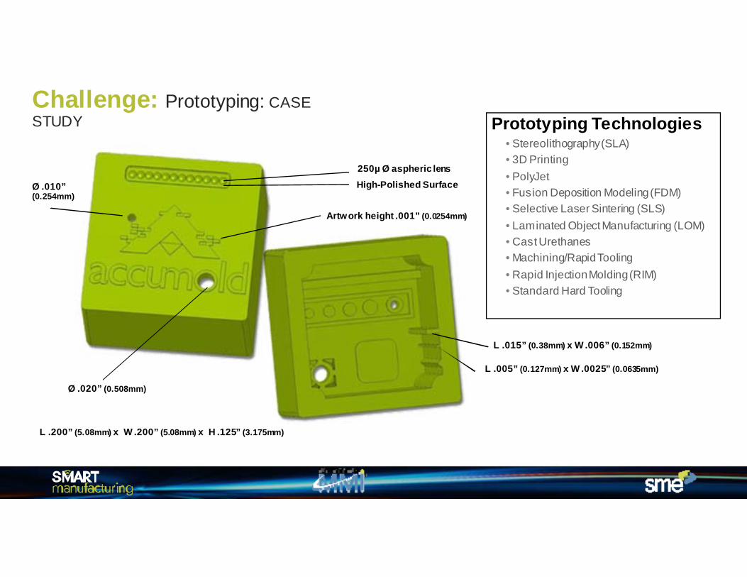
250µ Ø aspheric lens
Artwork height .001” (0.0254mm)
Ø .010” (0.254mm)
Ø .020” (0.508mm)
L .015” (0.38mm) x W .006” (0.152mm)
L .005” (0.127mm) x W .0025” (0.0635mm)
High-Polished Surface
L .200” (5.08mm) x W .200” (5.08mm) x H .125” (3.175mm)
Challenge: Prototyping: CASE STUDY Prototyping Technologies
• Stereolithography(SLA)• 3D Printing• PolyJet• Fusion Deposition Modeling (FDM)• Selective Laser Sintering (SLS)• Laminated Object Manufacturing (LOM)• Cast Urethanes• Machining/Rapid Tooling• Rapid Injection Molding (RIM)• Standard Hard Tooling

SLA Machined
PolyJet Micro-Mold®
SLA Machined
PolyJet Micro-Mold®
Challenge: Prototyping: CASE STUDY Results

SLA
Mac
hine
d
PolyJ
et
Mic
ro-M
old®
Challenge: Prototyping: CASE STUDY Results

Gate
Accumold Part
Materials• PEEK, Ultem®, LCP Nylon…• TPE / TPU• Filled materials: glass, carbon…• Optical Grades• Medical / Implantable Grades• Attenuated Materials• Specialty Materials
Challenge: Material Selection & Feature Performance

.1276” (3.241mm)
.003” (76µm)
.200” (5.08mm)
42:1 Max Aspect Ratio
GateLocation
The relationship between material selection and feature performance at the micro scale.
The Resins1. Polyethylene (PE)2. Polypropylene (PP)3. Polyamide (Nylon)4. Polycarbonate (PC)5. Polysulfone(PSU)6. Polyoxymethylene(POM)7. Polybutylene Terephthalate
(PBT)8. Polymethyl Methacrylate
(PMMA)9. Polyether Ether Ketone (PEEK)10. Polyetherimide(PEI)11. Liquid Crystal Polymer (LCP)
Challenge: Material Selection & Feature Performance: CASE STUDY

Picking your material:Where Do You Turn for Expertise?
• “The wall thickness would require an increase of 5x to 10x the current .003” in order to fill.”
• “Molding the part thicker and grind it down to the desired thickness.”
• “In looking at the part, the .003” section will not fill any of the listed materials. In fact, I believe you will be hard pressed to find a thermoplastic material that would fill that .0127” long, .003” wall.”
• “I do believe you would need to be in the .015” wall thickness zone.”
• “We would suggest increasing the .003” wall thickness to at least .015” or, better yet, .030” in order to improve moldability.
• “In my opinion filling this geometry would not be possible in a production environment. I would consider trying to mold a PP at approximately .016” -.018” and an Acetal 9 melt at .025”.
Challenge: Material Selection & Feature Performance: CASE STUDY

42:1
Polyethylene (PE) Polypropylene (PP)
Polyamide (Nylon) Polycarbonate (PC) Polysulfone (PSU)
Polyoxymethyle ne (POM)
Polybutylene Terephthalate (PBT)
Polymethyl Methacrylate (PMMA)
Polyether Ether Ketone (PEEK)
Polyetherimide (PEI)
Liquid Crystal Polymer (LCP)
42:1
18:1 14:1 14:1
42:1
25:1
26:1
3:1
10:1
42:1
.003” (76µm)Thin Wall
* Full length .1276” (3.241mm)
Material selection alone can have a profound effect on
feature performance.
Challenge: Material Selection & Feature Performance: CASE STUDY: RESULTS

70µm
Ø 100µm lens w/ 125µm base radius | PEI (Ultem®)
Challenge: Material Selection & Feature Performance

Quest 450
250µ
250µ
Zygo 7300
Metrology
Handling
Packaging
High Speed Automation 24 Cavity with 2 pairs of lead-strip. Each pair of lead-strip wascrimped and fed thru the mold. The molded product was thenfed to a testing and singulation die for packaging. The systemhad an annual volume of 30M parts.
Challenge: Metrology, Handling, & Packaging

Micro-Molding Alignment Spacer
• 800µm x 380µm x 300µm• Material: LCP
This part is made of LCP and is Accumold’s smallest commercial part to date. It measures 800µm x 380µm x 360um. 144,000 parts weigh 1 oz. Part handling more of an issue with this part than the tool build and production.
Pushing the Limits: What can you do with Micro Molding?
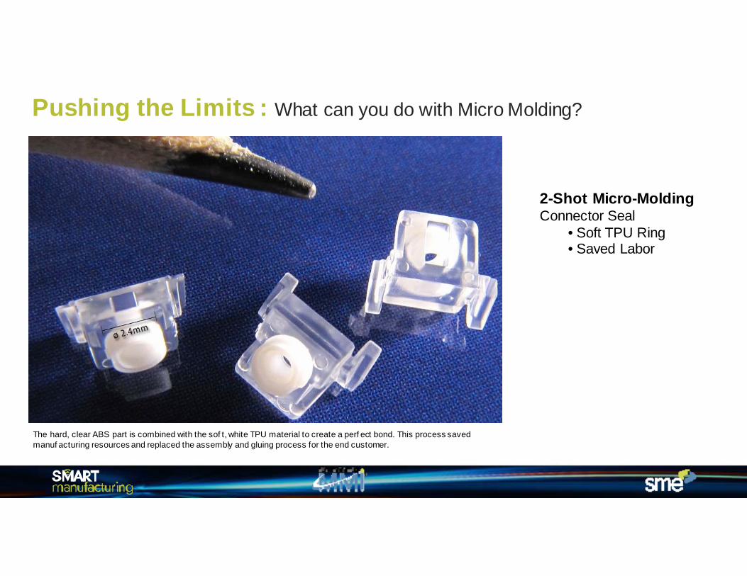
2-Shot Micro-Molding Connector Seal
• Soft TPU Ring• Saved Labor
The hard, clear ABS part is combined with the sof t, white TPU material to create a perf ect bond. This process saved manuf acturing resources and replaced the assembly and gluing process for the end customer.
Pushing the Limits : What can you do with Micro Molding?

OvermoldMedical
• Flex-Circuit Overmolding• Material TPE
This part requires delicate handling of the f lex circuit during processing. Careful shut-offs on the mold were require to not damage the circuit. The two orange parts are molded simultaneously with a dual gate setup.
Pushing the Limits : What can you do with Micro Molding?

Micro-Molding Insert Molding
• Singulation Die-Intergrated• Delicate Insert Media
This part shows an example of advanced insert molding capabilities where a delicate filter was molded into a plastic housing. This required the mold to be built in such a precise fashion so that the insert material could articulate through the mold during processing and not be destroyed in the process while keeping the tolerances tight within the part itself. The part is approximately 2mm in diameter.
Pushing the Limits : What can you do with Micro Molding?

Complex Micro MoldingHand-loaded Inserts
• Unique Multi-Slide Design• Special Packaging
These two parts are internal chassis f or hearing instruments. The v ery complex larger part on the bottom has 3 discreet pins that are ov ermolded simultaneously. The smaller part at the top has 5 discrete contacts that are overmolded as well.
Pushing the Limits : What can you do with Micro Molding?

Ø 400µm x12µm tall
Ø 25µm x1µm tall
Ø 10µm x0.5µm tall
Technology Highlight: MSE: Micro Structure Enhancement

Laser
Modified Polymer
Activated additive byLaser ablation
Molded Part
Laser Traced
Plated Part
Examples:
2-Shot – Non-Laser Process
CAD Design:
Technology Highlight: LDS: Laser Direct Structuring / 3D-MID

• SmartManufacturingSeries.com
Thank You!
QUESTIONS?