Design for Additive Manufacturing: A Method to Explore Unexplored
14
DESIGN FOR ADDITIVE MANUFACTURING: A METHOD TO EXPLORE UNEXPLORED REGIONS OF THE DESIGN SPACE David W. Rosen The George W. Woodruff School of Mechanical Engineering, Georgia Institute of Technology, Atlanta, GA 30332-0405 [email protected] ABSTRACT Additive Manufacturing (AM) technologies enable the fabrication of parts and devices that are geometrically complex, have graded material compositions, and can be customized. To take advantage of these capabilities, it is important to assist designers in exploring unexplored regions of design spaces. We present a Design for Additive Manufacturing (DFAM) method that encompasses conceptual design, process selection, later design stages, and design for manufacturing. The method is based on the process-structure-property-behavior model that is common in the materials design literature. A prototype CAD system is presented that embodies the method. Manufacturable ELements (MELs) are proposed as an intermediate representation for supporting the manufacturing related aspects of the method. Examples of cellular materials are used to illustrate the DFAM method. 1 INTRODUCTION 1.1 Design for Additive Manufacturing Design for manufacturing (DFM) has typically meant that designers should tailor their designs to eliminate manufacturing difficulties and minimize costs. However, the improvement of rapid prototyping, or Additive Manufacturing (AM), technologies provides an opportunity to re-think DFM to take advantage of the unique capabilities of these technologies. Several companies are now using AM technologies for production manufacturing. For example, Siemens, Phonak, Widex, and the other hearing aid manufacturers use selective laser sintering (SLS) and stereolithography (SL) machines to produce hearing aid shells, Align Technology uses stereolithography to fabricate molds for producing clear braces (“aligners”), and Boeing and its suppliers use SLS to produce ducts and similar parts for F-18 fighter jets. In the first three cases, AM machines enable one-off, custom manufacturing of 10’s to 100’s of thousands of parts. In the last case, AM technology enables low volume manufacturing and, at least as importantly, piece part reductions to greatly simplify product assembly. More generally, the unique capabilities of AM technologies enable new opportunities for customization, improvements in product performance, multi-functionality, and lower overall manufacturing costs. These unique capabilities include: • Shape complexity: it is possible to build virtually any shape, lot sizes of one are practical, customized geometries are achieved readily, and shape optimization is enabled. • Material complexity: material can be processed one point, or one layer, at a time, enabling the manufacture of parts with complex material compositions and designed property gradients. • Hierarchical complexity: hierarchical multi-scale structures can be designed and fabricated from the microstructure through geometric mesostructure (sizes in the millimeter range) to the part-scale macrostructure. 402
Transcript of Design for Additive Manufacturing: A Method to Explore Unexplored

DESIGN FOR ADDITIVE MANUFACTURING: A METHOD TO EXPLORE UNEXPLORED REGIONS OF THE DESIGN SPACE
David W. Rosen
The George W. Woodruff School of Mechanical Engineering, Georgia Institute of Technology,
Atlanta, GA 30332-0405 [email protected]
ABSTRACT
Additive Manufacturing (AM) technologies enable the fabrication of parts and devices that are geometrically complex, have graded material compositions, and can be customized. To take advantage of these capabilities, it is important to assist designers in exploring unexplored regions of design spaces. We present a Design for Additive Manufacturing (DFAM) method that encompasses conceptual design, process selection, later design stages, and design for manufacturing. The method is based on the process-structure-property-behavior model that is common in the materials design literature. A prototype CAD system is presented that embodies the method. Manufacturable ELements (MELs) are proposed as an intermediate representation for supporting the manufacturing related aspects of the method. Examples of cellular materials are used to illustrate the DFAM method.
1 INTRODUCTION 1.1 Design for Additive Manufacturing
Design for manufacturing (DFM) has typically meant that designers should tailor their designs to eliminate manufacturing difficulties and minimize costs. However, the improvement of rapid prototyping, or Additive Manufacturing (AM), technologies provides an opportunity to re-think DFM to take advantage of the unique capabilities of these technologies. Several companies are now using AM technologies for production manufacturing. For example, Siemens, Phonak, Widex, and the other hearing aid manufacturers use selective laser sintering (SLS) and stereolithography (SL) machines to produce hearing aid shells, Align Technology uses stereolithography to fabricate molds for producing clear braces (“aligners”), and Boeing and its suppliers use SLS to produce ducts and similar parts for F-18 fighter jets. In the first three cases, AM machines enable one-off, custom manufacturing of 10’s to 100’s of thousands of parts. In the last case, AM technology enables low volume manufacturing and, at least as importantly, piece part reductions to greatly simplify product assembly. More generally, the unique capabilities of AM technologies enable new opportunities for customization, improvements in product performance, multi-functionality, and lower overall manufacturing costs. These unique capabilities include:
• Shape complexity: it is possible to build virtually any shape, lot sizes of one are practical, customized geometries are achieved readily, and shape optimization is enabled.
• Material complexity: material can be processed one point, or one layer, at a time, enabling the manufacture of parts with complex material compositions and designed property gradients.
• Hierarchical complexity: hierarchical multi-scale structures can be designed and fabricated from the microstructure through geometric mesostructure (sizes in the millimeter range) to the part-scale macrostructure.
402

New CAD and DFM methods are needed in order to take advantage of these capabilities. In the hearing aid and aligner cases, new CAD systems had to be developed to enable efficient shape modeling and part design. During a U.S. government sponsored study of European researcher groups [18], many researchers said that they foresaw the lack of capable CAD tools as a serious impediment for their research and for the utilization of AM technologies for production manufacturing applications. However, if suitable CAD and DFM methods and tools can be developed, designers can design devices with significantly improved performance that fully utilize material, and with efficient manufacturing processes. With the shape, material, and hierarchical complexity capabilities, DFM can move from an emphasis on cost minimization to a focus on achieving heretofore unrealizable capabilities. Hence, a new definition of DFM can be proposed. DFM for Additive Manufacturing (DFAM) is the:
Synthesis of shapes, sizes, geometric mesostructures, and material compositions and microstructures to best utilize manufacturing process capabilities to achieve desired performance and other life-cycle objectives.
In order to achieve this new concept of DFAM and enable wide ranges of new applications, new approaches, methods, and tools are needed. The focus in this paper is on the application of cellular materials to replace bulk materials. Cellular materials provide many more design variables, but with those variables comes more complexity. New design, analysis, and manufacturing technologies are needed as a result.
1.2 Cellular Materials The concept of designed cellular materials is motivated by the desire to put material only
where it is needed for a specific application. From a mechanical engineering viewpoint, a key advantage offered by cellular materials is high strength accompanied by a relatively low mass. These materials can provide good energy absorption characteristics and good thermal and acoustic insulation properties as well [8]. Cellular materials include foams, honeycombs, lattices, and similar constructions. When the characteristic lengths of the cells are in the range of 0.1 to 10 mm, we refer to these materials as mesostructured materials. Mesostructured materials that are not produced using stochastic processes (e.g. foaming) are called designed cellular materials. In this paper, we focus on designed lattice materials.
In the past 10 years, the area of lattice materials has received considerable attention due to their inherent advantages over foams in providing light, stiff, and strong materials [1]. Lattice structures tend to have geometry variations in three dimensions; some of our designs are shown in Figure 1. As pointed out in [5], the strength of foams scales as ρ1.5, whereas lattice structure strength scales as ρ, where ρ is the volumetric density of the material. As a result, lattices with a ρ = 0.1 are about 3 times stronger than a typical foam. The strength differences lie in the nature of material deformation: the foam is governed by cell wall bending, while lattice elements stretch and compress. The examples in Fig. 1 utilize the octet-truss (shown on the left), but many other lattice structures have been developed and studied (e.g., kagome, Kelvin foam). We have developed methods for designing lattice mesostructure for parts [25] and have developed design-for-manufacturing rules for their fabrication in SL.
Methods of continuum mechanics have been applied to various mesostructured materials. Ashby and co-workers wrote a book on metal foam design and analysis [1]. They and others have applied similar methods to the analysis of lattice structures. The octet truss in Fig. 1 has been extensively analyzed. Deshpande et al. [5] treated the octet truss unit cell as a collection of
403
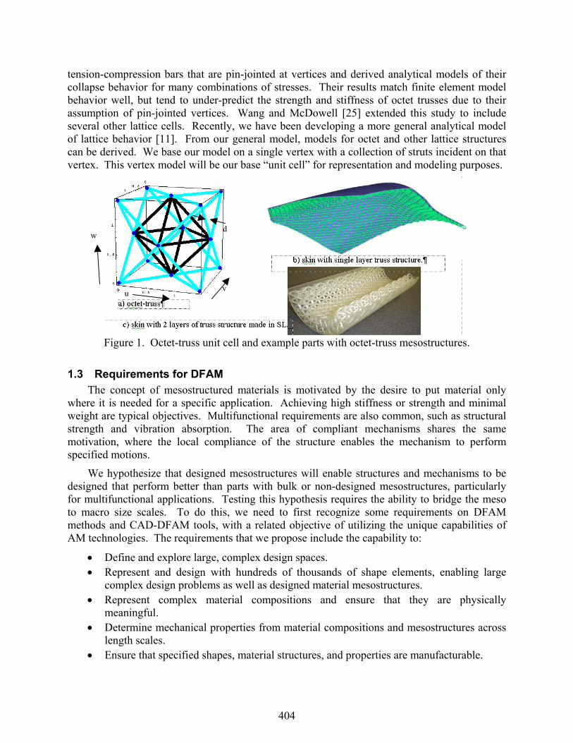
tension-compression bars that are pin-jointed at vertices and derived analytical models of their collapse behavior for many combinations of stresses. Their results match finite element model behavior well, but tend to under-predict the strength and stiffness of octet trusses due to their assumption of pin-jointed vertices. Wang and McDowell [25] extended this study to include several other lattice cells. Recently, we have been developing a more general analytical model of lattice behavior [11]. From our general model, models for octet and other lattice structures can be derived. We base our model on a single vertex with a collection of struts incident on that vertex. This vertex model will be our base “unit cell” for representation and modeling purposes.
Figure 1. Octet-truss unit cell and example parts with octet-truss mesostructures.
1.3 Requirements for DFAM The concept of mesostructured materials is motivated by the desire to put material only
where it is needed for a specific application. Achieving high stiffness or strength and minimal weight are typical objectives. Multifunctional requirements are also common, such as structural strength and vibration absorption. The area of compliant mechanisms shares the same motivation, where the local compliance of the structure enables the mechanism to perform specified motions.
We hypothesize that designed mesostructures will enable structures and mechanisms to be designed that perform better than parts with bulk or non-designed mesostructures, particularly for multifunctional applications. Testing this hypothesis requires the ability to bridge the meso to macro size scales. To do this, we need to first recognize some requirements on DFAM methods and CAD-DFAM tools, with a related objective of utilizing the unique capabilities of AM technologies. The requirements that we propose include the capability to:
• Define and explore large, complex design spaces. • Represent and design with hundreds of thousands of shape elements, enabling large
complex design problems as well as designed material mesostructures. • Represent complex material compositions and ensure that they are physically
meaningful. • Determine mechanical properties from material compositions and mesostructures across
length scales. • Ensure that specified shapes, material structures, and properties are manufacturable.
u v
w d
404

In order to achieve these requirements, several new technologies are required. Our approach has five main elements (requirements that they address are appended):
• Process-Structure-Property-Behavior-Function framework for Design for Additive Manufacturing.
• Cellular materials: methods for topology layout, high-fidelity analysis, simplified analysis.
• “Manufacturable Elements” (MEL’s) that contain geometry, material, properties, and uncertainties in these quantities.
• DFAM templates that enable formulation and solution of typical DFM problems. • Improved search algorithms needed to explore large, complex design space.
Each of these five new technologies is addressed, at least in part, in this paper. In the next section, the framework for our DFAM approach is presented, providing the larger context for this research. In Section 3, the technologies being developed for DFAM are presented, covering our bio-inspired conceptual design, cellular materials layout, and Manufacturing Elements methods. An example is presented in Section 4 that covers part design, manufacturability analysis, process planning, and process simulation. Conclusions are drawn in the final section.
2 FRAMEWORK FOR DFAM We will borrow the process-structure-property relationships framework from the materials
science field to model a design [13]. The manufacturing process space, P, consists of process plans with sequences of operations and values of process variables. Structure space, S, contains information about the geometric, topological, and material structures of a design. Property space T contains information about part properties that are derivable from S using physical principles; e.g., mechanical, thermal, and electrical properties. Behavior space, B, contains information about a part’s actual behavior given some loading and boundary conditions, while function space, F, describes the desired behavior of the system. The relationships among these spaces are shown in Fig. 2.
Mappings are defined among these spaces. Mapping Φ represents a manufacturing analysis that determines material composition and microstructure, and possibly as-manufactured part shape from a process plan. Mapping Γ represents a material science analysis of a material, and possibly part geometry, to arrive at a set of mechanical and other properties. It is possible that this mapping can be determined once, then reused for different applications (not design- or part-specific). Some standard engineering tasks can be described using this notation: Ψ: (S,T) → B [engineering analysis], Φ-1: S → P [process planning], and ∆: (S,B) → (S*, P, T) [design and DFAM].
ProcessP
StructureS
PropertyT
BehaviorB
Material CompositionMicrostructure
Mechanical, Electrical, Thermal, … Properties
Actual behavior
Φ Γ ∆
Analysis
Design
FunctionF
Desired behavior
ΛProcess
PStructure
SProperty
TBehavior
B
Material CompositionMicrostructure
Mechanical, Electrical, Thermal, … Properties
Actual behavior
Φ Γ ∆
AnalysisAnalysis
DesignDesign
FunctionF
Desired behavior
Λ
Fig. 2: Process-Structure-Property-Behavior Mappings.
405

The mappings shown in Fig. 2 capture important relationships among design attributes across several size scales. However, additional richness enables the multi-scale aspects of both geometric and material models to be captured. The process, structure, and property models will be divided into geometric and material models in order to emphasize their different decompositions. Fig. 3 shows the framework from Fig. 2 with separate Material and Geometry levels. As one moves from right to left, the relevant size scales decrease. Similarly, when one moves from top to bottom, smaller size scales become important. These levels and size scales will be further explained in the next section.
MaterialΦ Γ ∆
PG
PMProcess
TMProperty
SMStructure
SG B Behavior
PMProcess
SMStructure
SG TGGeometry
Decreasing size scale
Decreasing size scale
MaterialΦ Γ ∆
PGPG
PMProcess
TMProperty
SMStructure
SG
SMStructure
SG B BehaviorB Behavior
PMProcess
SMStructure
SG
SMStructure
SG TGTGGeometry
Decreasing size scale
Decreasing size scale
Fig. 3: Expanded DFAM Framework with Geometry and Material Layers.
3 DFAM METHOD, SYSTEM, AND TECHNOLOGIES 3.1 Bio-inspired Conceptual Design
The overall DFAM method begins with a conceptual design stage that is based on biomimicry. Our approach is an extension of the Pahl and Beitz design method [15]. For some key subfunctions identified by the designer, a bio-inspired approach can be used to leverage “solutions” from nature. Our method is called “reverse engineering biological systems” and is intended to help designers to develop solution and working principles by abstracting from the working principles used in biological system. Resulting “biological strategies” can be used as creative stimuli in the search for engineering principles.
As seen in Figure 1, there are four key research areas in the method for reverse engineering biological systems: biological systems identification, biological representation, biological strategy extraction, and strategy abstraction. The uniqueness of this method lies in the last three research areas, whereas biological system identification is currently being addressed by other researchers [3,4,21,22].
A key step in extracting biological strategies is to develop a model of the biological system’s behavior. Such behavior models are critical in identifying engineering systems where the biological system may be applied, as well as in adapting the biological system to the engineering system. We are
Systematic Design Methodology
Planning and Clarification of Task
Conceptual Design
Detail Design
Embodiment Design
Biological Strategy
Extraction
Strategy Abstraction
Biological Representation Abstract essential
problemAbstract essential
problem
Establish function structures
Establish function structures
Search for working principles
Search for working principles
…….…….
Biological System
Identification
Systematic DesignMethodology
ConceptualDesign
Rev
erse
Eng
inee
ring
Systematic Design Methodology
Planning and Clarification of Task
Conceptual Design
Detail Design
Embodiment Design
Biological Strategy
Extraction
Strategy Abstraction
Biological Representation Abstract essential
problemAbstract essential
problem
Establish function structures
Establish function structures
Search for working principles
Search for working principles
…….…….
Biological System
Identification
Systematic DesignMethodology
ConceptualDesign
Rev
erse
Eng
inee
ring
Fig. 4 Conceptual design method.
406

using hierarchical Petri nets [28] as the basis of our behavioral models. Specifically, we believe that modeling the discrete physical states of the biological system as places and changes in these discrete states as transitions in the Petri net framework, while still holding the properties of reachability, liveness, and boundedness.
We have applied the bio-inspired conceptual design method to the design of morphing aircraft wing skins (based on the sea cucumber and human muscle) [27] and of artificial kidneys (based on human kidneys). We will conclude this presentation by stating that the output of conceptual design should be a detailed behavior model as well as working principles for each function in the behavior model. This information drives later design stages. Since the method is not directly related to SFF, we will not explain it further in this paper.
3.2 DFAM Method and System The overall DFAM method consists of a traversal of the frameworks in Figs. 2 and 3 from
Function to Process, then back again to Behavior. The traversal from Function to Process can be called design, where functional requirements are mapped to properties and geometry that satisfy those requirements to structures and through process planning to arrive at a potential manufacturing process. Reverse direction, one can simulate the designed device and its manufacturing process to determine how well it satisfies the original requirements.
Fig. 5 shows the proposed DFAM system that embodies the method outlined above. To the right in Fig. 5, the designer can define the DFAM synthesis problem, using an existing problem template if desired. For different problem types, different solution methods and algorithms will be available. Analysis codes, including FEA, boundary element, and specialty codes, will be integrated to determine design behavior. In the middle of Fig. 5, the heterogeneous solid modeler (HSM) is illustrated (heterogeneous denotes that material and other property information will be modeled). Libraries of materials and mesostructures enable rapid construction of design models. To the left, the manufacturing modules are shown. Both process planning and simulation modules will be included. After planning a manufacturing process, the idea is that the process will be simulated on the current design to determine the as-manufactured shapes, sizes, mesostructures, and microstructures. The as-manufactured model will then by analyzed to determine whether or not it actually meets design objectives.
3.3 Synthesis Methods To date, we have used a synthesis method based on Particle Swarm Optimization (PSO),
which is an extension of genetic algorithms (GA), to perform parametric and limited topological optimization of structures and compliant mechanisms. PSO simulates the movement of birds in a flock, where individuals adjust their flying according to their experience and other individuals’ experiences during searches for food [12]. It combines local search with global search, and enables cooperative behavior among individuals (“birds”), as well as the competition modeled using GA. Hence, PSO often converges more quickly than GA and was selected for the design synthesis of cellular structures [7].
In the future, we intend to adopt a two-stage method for multifunctional topology design applications that demand not only targeted structural performance but also satisfactory performance in a distinct secondary functional domain [18]. Intended secondary domains, such as conjugate heat transfer or vibration absorption, are governed by non-local, scale-dependent phenomena that are not directly amenable to standard homogenization or interpolation techniques underlying discrete or continuum topology optimization techniques. For this class of
407

applications, conventional approaches involve either selecting a standard topology [22] or identifying a final topology via conventional structural topology optimization [2,24] and thereby fixing its topology for subsequent multifunctional customization. Instead, a two-stage approach for multifunctional topology design is promising in which both topology and dimensions are adjusted for multifunctional performance requirements. For the first stage, a robust structural topology design process has been developed for designing a preliminary topology with structural performance that meets targets as closely as possible while remaining relatively insensitive to bounded adjustments in the topology itself and its dimensions. In the second stage, the topology is modified, within the acceptable bounds, to improve its multifunctional performance in a secondary domain. The method relies on approximate physics-based models to facilitate rapid exploration of a broad design space and identification of promising multifunctional solutions that are verified subsequently with more detailed models.
3.4 CAD = Structure + Property The CAD system proposed here consists of the Structure and Property elements of Figs. 2
and 3. Our proposed geometric representation is a combination of implicit, non-manifold, and parametric modeling, with the capability of generating BReps when needed. Implicit modeling is used to represent overall part geometry, while non-manifold modeling is used to represent shape skeletons. Parametric modeling is necessary when decomposing the overall part geometry into cellular structures; each cell type will be represented as a parametric model.
ImplicitSolid
Modeler
Materials, Microstructure,Mesostructure
ManufacturingProcessPlanner
ManufacturingSimulator
DFAM SolutionMethods
AnalysisCodes
MaterialsMfg Processes Mesostructures DFAMTemplates
ProcessPlanning
Determineas-manufactured shapes, properties
1
3
2
4
CAD System DesignManufacturingImplicitSolid
Modeler
Materials, Microstructure,Mesostructure
ImplicitSolid
Modeler
ImplicitSolid
Modeler
Materials, Microstructure,Mesostructure
ManufacturingProcessPlanner
ManufacturingSimulator
ManufacturingProcessPlanner
ManufacturingSimulator
DFAM SolutionMethods
AnalysisCodes
DFAM SolutionMethods
AnalysisCodes
MaterialsMaterialsMfg ProcessesMfg Processes MesostructuresMesostructures DFAMTemplates
DFAMTemplates
ProcessPlanning
Determineas-manufactured shapes, properties
1
3
2
4
CAD System DesignManufacturing
Fig. 5: DFAM System and Overall Method.
Design problems are formulated and solved within the Design box. To support geometric and structure/property reasoning needs, the CAD system maintains a high fidelity models of device geometry, material composition, and property distribution within the device. Process planning and manufacturing process simulations are supported within the Manufacturing module. The set of databases at the bottom of Fig. 5 illustrate the libraries of models and templates that are integrated in the system. Unit cells for cellular materials, properties of metals and polymers, models of manufacturing processes, and design problem formulations (templates) are among the integrated information.
The approach taken to design with cellular materials is illustrated in Fig. 6. Typically, solid sections or thick walls of a part are to be replaced with a cellular structure in order to lighten the part, stiffen it, or for other functional reasons. The boundary surface of the part CAD model is partitioned into surface patches. Bezier or b-spline surface patches are fit to these patches. A
408

mapped meshing approach [24] is used to fill the solid section or line the boundary with cellular structure. A solid model of the cellular material is then generated using our hybrid modeling approach [23]. The resulting solid cellular model is suitable for process planning (Section 3.5).
Within the CAD system, non-manifold modeling is used to represent shape skeletons. For cellular structures, it is often sufficient to represent struts as line segments terminated by nodes. Radius parameters are associated with struts and nodes to enable reasoning about the 3D geometry of lattices and enable generation of 3D solid models, analysis models, and manufacturing models. We use a simple non-manifold model based on that of Gursoz et al. [9], which is particularly useful when representing lattices with skins.
3.5 Manufacturable Elements A Manufacturable ELement (MEL) is a predefined, parameterized decomposition of a
volumetric region of a part. For the lattice structures under investigation in this paper, MEL definition is straightforward: scan patterns and scan variables are associated with each strut in a unit cell. Consider the octet unit cell in Fig. 1 and assume it is being built in a SL machine vertically upward. For each layer in the SL build process, the unit cell is sliced by a plane. For the vertical struts, the intersection of the plane and the strut is a circle. For slanted struts, the intersection is an ellipse, while for horizontal struts, the intersection is a rectangle. Each case can be handled readily.
The cases for vertical and slanted struts are shown in Fig. 7. The notation is as follows: r = strut radius, W0 = laser beam radius, θ = strut angle, rl = major axis of ellipse (with minor axis = r), and p = (px, py) = center of intersected circle or ellipse. The specific parameters in the cases were determined empirically and give reasonable results for typical SL resins and laser scanning speeds. For example, case a) rl ≤ 1.4 W0 or 1.6 W0 or other multiple of W0 could have been selected and the laser irradiation time can be determined easily. However, long irradiation times can cause cured struts to become too thick, while short irradiation times may not enable the layer
Upper Side Surface
Lower Side Surface
Bottom
Divide bounding surface into surface patches
Fill part volume with conformal cells
Convert topological model to solid model
00.5
1
0 0.5 1
0
0.5
1
0
Select cell type from library
Upper Side Surface
Lower Side Surface
Bottom
Divide bounding surface into surface patches
Fill part volume with conformal cells
Convert topological model to solid model
00.5
1
0 0.5 1
0
0.5
1
0
Select cell type from library
Fig. 6 Cellular modeling approach.
409

to adhere to the previous one. The multiple 1.5 times W0 is a reasonable compromise value. For horizontal struts, cases b), c), and d) apply.
W0
rl
W0
rl
W0
r
xm-xm
W0
r
xm-xm
Scan is just a point 1 scan vector from x = -xm to x = xm. xm = rl - W0
Case a) rl ≤ 1.5 W0
Case b) r ≤ 2 W0
r
ym xm-xm
Scan 1
Scan 2
Scan 3
-ym
r
ym xm-xm
Scan 1
Scan 2
Scan 3
-ym
W0
r
W0
r
3 scan vectors: Scan 1 is same as case b),
Scan 2 is at y = -ym, Scan 3 is at y = ym. 2 2
01m l mx r y x W= − − ym = rl - 0.8 W0
Case c) r ≤ 3 W0 Case d) otherwise
Fig. 7 Scan pattern cases for sliced struts.
Using the standard SL exposure model from Jacobs [10], the irradiation time for points and scan speeds for lines can be computed easily. For reasonably long scan vectors (more than ~3 times the laser beam diameter), the exposure received at a point (y, z) in the vat by a scan along the x axis is given by
2 202
0
2( , , ) pz Dy WL
s
PE x y zW V
e eπ
−−= (1)
where PL = laser power [mW], Vs = scan speed [mm/s], and Dp = depth of penetration [mm] (taken to be a constant measure of a resin’s sensitivity to laser energy). SL resins are assumed to be cured (form a solid) when they receive exposure that is equal to or greater than a certain amount, called the resin’s critical exposure, Ec [mJ/mm2]. For a layer thickness of l = 0.1 mm, it is typical to cure the resin to a depth of 0.15 mm, or 1.5 times the layer thickness. This cure
410

depth reaches a maximum along a scan’s centerline (when y = 0). Eqn. 1 can be rearranged to solve for Vs as follows in order to compute the scan velocity to give a cure depth of 1.5 times the layer thickness:
1.5
0
2 p
lDL
sc
PVW E
eπ
−
= (2)
Substituting reasonable values for a SLA-250/50 machine (PL = 30 mW, W0 = 0.125 mm, Ec = 0.12 mJ/mm2, l = 0.1mm, Dp = 0.1524 mm) yields a scan speed of about 600 mm/s. At this speed, the width of a cured scan line is 0.172 mm for the numbers in this example, or about 2/3 of the laser beam diameter. The cure model presented briefly here has been implemented into a MEL for lattice unit cells fabricated using SL. By adjusting scan speeds, it is possible to fine-tune a process plan such that lattice struts have appropriate sizes, which has been formulated as a parameter estimation problem and solved using nonlinear least-squares methods [19].
3.6 Process Planning Process planning is denoted by the mapping Φ : S → P. Using the notation in Fig. 3,
process planning consists of two parts, one dealing with geometry decomposition (Φ : SG → PG) and the other for assigning values to process variables (Φ : SM → PM) to process the material appropriately. Geometric decomposition and process modeling are governed by the specific type of MEL selected. In this section, we will briefly present the process planning formulation.
Parameter estimation, or “inverse design,” methods can be applied to AM process planning to enable plans to be designed that meet design requirements on shape, surface finish, tolerances, and potentially other properties such as stiffness. Inverse design methods were developed in the heat transfer area [14]. A typical application of inverse design methods is to layout heater elements in a furnace, where heater positions are to be adjusted to achieve a desired temperature distribution. Parameter estimation methods for SL will be used to achieve a desired surface finish. The surfaces of a part fabricated in SL are defined by where the resin reaches a high enough crosslink density to remain solid, which is related to the exposure received from the laser [10]. The challenge is to determine appropriate exposure levels for each laser scan as it draws part cross sections such that part surfaces are precisely positioned and shaped.
The inverse design problem for SL process planning can be stated as: find exposure values along each scan vector to minimize the deviation of exposure across part surfaces from the desired constant Ec value. A general mathematical problem formulation is shown in Fig. 8 [19]. The constraint models the height of the part at a point P on its surface, which has to be equal to the summation of the layer thicknesses at point P and the thickness of the Compensation Zone at point P. The objective function to be minimized models the deviation of exposure at a set of grid points (on the part’s down-facing surfaces) from the critical exposure, Ec.
Given: Geometry of the part g(x,y,z) Material properties: energy absorption, α, critical exposure, Ec. Find: LTi, OCip, CZp Satisfy:
Constraints: 1
n
p i pi
h LT CZ=
= +∑
Bounds: on variables
Minimize: 1( )
11
im p
i ip mn LT CZLT OC
ie e
αα =
− +∑ +
=
−∑
for all grid points P
Fig. 8 Math formulation of general process planning problem.
411

Since there are many more scan vectors than measurement points mj, least-squares solution techniques are appropriate. We can take advantage of the MEL model by utilizing MEL parameterizations to sample each MEL and to compute exposure values. The least-squares fitting problem can be formulated as follows. The squared error term is the square of the objective function from Fig. 8, denoted by D (Eqn. 3). This error term is to be minimized, so the derivative of D, with respect to the vector of variables U, involves the Jacobian of the system. Since J is nonlinear, an iterative solution technique must be used to solve for the unknowns, which are the scanning velocities and some scan vector positions. Both Gauss-Newton and Levenburg-Marquardt methods [16] are frequently used to solve such problems. In our work, we use Matlab’s non-linear least-squares solver, lsqnonlin, which selects from Gauss-Newton and Levenburg-Marquardt algorithms to solve problems.
4 EXAMPLE As an example, a cover plate for an aerospace
structure will be redesigned to use lattice structure to stiffen it. The cover plate is shown in Fig. 7. It is approximately 300x350 mm in size and 3 mm thick. The thickness will be increased to 9 mm to accommodate the lattice structure, while the skin thickness will be decreased to 1.5 mm. A typical design-manufacture scenario will be presented that includes the decomposition of the cover plate geometry into cells, the synthesis of the resulting cellular structure to achieve a desired stiffness with minimum weight, and the decomposition of the synthesized geometry into manufacturing operations using MELs. The central region of the plate, inside of the bolt hole pattern, is offset by the desired thickness of the lattice structure. This central region is then decomposed into lattice cells by mapping one layer of octet truss cells into the region. A nominal size of 8x8x8 mm is chosen for the cells, which results in 14,960 struts.
To achieve the objectives of a target stiffness (modeled by a target deflection) and minimum weight, a shape optimization problem is solved. Lattice strut diameters are the design variables. Rather than allowing each of the strut diameters to be a variable, we adopt the strategy of grouping struts into clusters based on an initial structural analysis. Ten clusters were used, corresponding to 10 design variables for optimization, since in our experience good results are often achieved. Diameter variables can vary between 0.2 and 1.2 mm, corresponding to the minimum manufacturable strut size on the lower end. A reasonably large strut size is chosen for the maximum of the range; if the strut diameters become larger, the cells start to lose porosity. The loading condition for size optimization is an area load in the plate center of 0.064 N/mm2 applied to a 60x60 mm area.
Size optimization is performed in ANSYS. Input files are automatically generated for ANSYS from the cellular model. The first-order gradient optimization method is used. Results are shown in Tab. 1. The number of optimization iterations, maximum stress, maximum deflection of the cover plate, and part volume are reported, along with the values of the diameter variables. This problem was not sensitive to the number of clusters used. Convergence of the
Fig. 9 Cover plate example part.
412

cluster diameters was smooth, with the lower stress clusters becoming thicker, some mid-level clusters fluctuating up or down, as shown in Tab. 1. The final cover plate design is shown in Fig. 8. Note that various strut diameters can be seen in the zoomed view.
Diameters Initial [mm] Final [mm] Initial [N/mm2] Final [N/mm2] D1 0.2 0.2 Max. Stress -278.15 57.33 D2 0.4 0.6 D3 0.6 0.79 Volume Initial [mm3] Final [mm3] D4 0.6 0.73 8008 20,314 D5 0.8 0.84 D6 0.8 0.73 D7 1.0 0.88 D8 1.0 1.04 D9 1.2 1.2 D10 1.2 1.2
Tab. 1: Lattice optimization results.
The next step in the DFAM process is process planning to ensure manufacturability. Each unit cell of the lattice structure is represented by a lattice MEL from Section 3.4. Recall that the relative orientation of each strut to the build direction dictates how it will be decomposed into manufacturing operations, which, in the case of SL or SLS are laser scans. Each strut is modeled as a MEL to facilitate process planning and process simulation. Process planning results for two struts were presented in an earlier paper [17].
5 CONCLUSIONS Two advances are reported in this paper. First, a new Design for Additive Manufacturing
(DFAM) method was presented that supports part and specification modeling, bio-inspired conceptual design, cellular material layout, process planning, and manufacturing simulations. Second, Manufacturable ELements (MELs) were proposed as an intermediate representation for supporting the manufacturing related aspects of the method. Specific conclusions from this work include:
• Cellular material types provide one method for providing mesostructure within a part for achieving improved stiffness, strength, or other functional requirements, as compared to monolithic materials.
• The process-structure-property-behavior framework can be expanded for the design for additive manufacturing of structures and devices.
• Bio-inspired conceptual design is a promising “front end” for the DFAM CAD system presented here.
• Manufacturing ELements (MELs) enable process planning within discrete regions of a part and also enable process simulation. MELs represent one approach to achieving
Fig 10 Cover plate with optimized lattice structure (shown on only half of the plate).
413
shape-specific process planning, rather than a reliance on general purpose process planning methods, typical of the AM industry at present.
• Design for Additive Manufacturing should be concerned with the exploration of expanded design spaces, rather than the focus on constraints imposed by the manufacturing processes, as is typical of DFM methods.
6 ACKNOWLEDGEMENTS We gratefully acknowledge the U.S. National Science Foundation, through grants IIS-
0120663 and DMI-0522382, and the support of the Georgia Tech Rapid Prototyping and Manufacturing Institute member companies, particularly Pratt & Whitney, for sponsoring this work. The assistance of Jamal Wilson is gratefully acknowledged for Section 3.1.
7 REFERENCES [1] Ashby, M.F.; Evans, A.; Fleck, N. A.; Gibson, L. J.; Hutchinson, J. W.; and Wadley, H. N. G.
(2000) Metal Foams: A Design Guide, Butterworth-Heinemann, Woburn, MA. [2] Bendsoe, M.P., Kikuchi, N. (1988) "Generating optimal topologies in structural design using a
homogenization method," Computer Methods in Applied Mechanics and Engineering, vol. 71, pp. 197-224.
[3] Chiu, I. and L.H. Shu. Bridging Cross-Domain Terminology for Biomimetic Design. in 2005 IDETC Design Theory and Methodology. 2005. Long Beach, CA: ASME.
[4] Chiu, I. and L.H. Shu. Natural Language Analysis for Biomimetic Design. in 2004 DETC Design Theory and Methodology. 2004. Salt Lake City, Utah: ASME.
[5] Deshpande V.S.; Fleck N.A.; Ashby M.F. (2001) “Effective Properties of the Octet-Truss Lattice Material,” J. Mechanics and Physics of Solids, 49(8), 1747-1769.
[6] Ensz, M.; Storti, D.; Ganter, M. (1998) “Implicit Methods for Geometry Creation,” International Journal of Computational Geometry Applications, 8(5,6), 509–36.
[7] Fourie, P.C., Groenwold, A.A. (2002) “The particle swarm optimization algorithm in size and shape optimization,” Structural and Multidisciplinary Optimization, vol. 23, pp. 259 - 267.
[8] Gibson, L. J.; Ashby, M. F. (1997) Cellular Solids: Structure and Properties, Cambridge University Press, Cambridge, UK.
[9] Gursoz, E.L.; Choi, Y.; Prinz, F.B. (1988) “Vertex-based Representations of Non-manifold Boundaries, Geometric Modeling for Product Engineering,” IFIP WG5.2, Rensselaerville, NY, M. J. Wozny, J. U. Turner, and K. Preiss, (eds.), North-Holland, Amsterdam, 107-130.
[10] Jacobs, P. F. (1992) Rapid Prototyping & Manufacturing, Fundamentals of Stereolithography, SME, Dearborn, MI.
[11] Johnston, S.R.; Reed, M.; Wang, H.; Rosen, D.W.: Analysis of Mesostructure Unit Cells Comprised of Octet-truss Structures, Solid Freeform Fabrication Symposium, Austin, TX, Aug. 14-16, 2006, 421-432.
[12] Kennedy, J., Eberhart, R.C. (1995) “Particle swarm optimization,” Proceedings of IEEE International Conference on Neural Networks, Piscataway, NJ, pp. 1942-1948.
[13] Olson, G. B., (1997) “Computational Design of Hierarchically Structured Materials,” Science, 277(5330), 1237-1242.
[14] Özisik, M.N.; Orlande, H.R.B. (2000) Inverse Heat Transfer, Taylor & Francis, New York. [15] Pahl, G. and W. Beitz, Engineering Design: A Systematic Approach. 2 ed. 1996, London: Springer-
Verlag. [16] Press, W.H.; Teukolsky, S.A.; Vettering, W.T.; Flannery, B.P. (1992) Numerical Recipes in C,
Chapter 15, 2nd Edition, Cambridge University Press, Cambridge, UK. [17] Rosen, D.W., “Computer-Aided Design for Additive Manufacturing of Cellular Structures,” Int’l
CAD Conference and Exhibition, Honolulu, June 25-29, 2007.
414

[18] Rosen, D.W.; Atwood, C.; Beaman, J.; Bourell, D.; Bergman, T.; Hollister, S.: Results of WTEC Additive/Subtractive Manufacturing Study of European Research, Proc. SME Rapid Prototyping & Manufacturing Conference, paper # TP04PUB211, Dearborn, MI, May 10-13, 2004. Also, see: http://wtec.org/additive/welcome.htm for the complete report.
[19] Sager, B.; Rosen, D.W.: Use of Parameter Estimation For Stereolithography Surface Finish Improvement, Proc. Solid Freeform Fabrication Symposium, Austin, TX, Aug. 1-3, 2005.
[20] Seepersad, C.C., Allen, J.K., McDowell, D.L., Mistree, F. (2006) “Robust Design of Cellular Materials with Topological and Dimensional Imperfections,” ASME J. Mechanical Design, Vol. 128, p. 1285.
[21] Vakili, V. and L.H. Shu. Towards Biomimetic Concept Generation. in 2001 DETC Design Theory and Methodology. 2001. Pittsburgh, PA: ASME.
[22] Vincent, J.F.V., Mann, D.L. “Systematic technology transfer from biology to engineering,” Philosophical Transactions of the Royal Society of London A, 2002. 360: p. 159-173.
[23] Wang, H.; Chen, Y.; Rosen, D. W. (2005) “A Hybrid Geometric Modeling Method for Large Scale Conformal Cellular Structures,” Proc. ASME Computers and Information in Engineering Conference, paper DETC2005-85366, Long Beach, CA, Sept 24-28.
[24] Wang, H.; Rosen, D.W. (2002) “Parametric Modeling Method for Truss Structures,” ASME Computers and Information in Engineering Conference, paper DETC2002/CIE-34495, Montreal, Sept. 29-Oct 2.
[25] Wang, A.-J.; McDowell, D.L. (2003) “Optimization of a metal honeycomb sandwich beam-bar subjected to torsion and bending,” Int’l J. of Solids and Structures, 40(9), 2085-2099.
[26] Watts, D.M., Hague, R.J., (2006) “Exploiting the Design Freedom of RM,” Proc Solid Freeform Fabrication Symp., Austin, TX, pp. 656-667, Aug. 14-16.
[27] Wilson, J.O., Rosen, D.W. (2007) “Systematic Reverse Engineering of Biological Systems,” Proc. ASME Design Theory and Methodology Conf., paper DETC2007-35395, Las Vegas, Sept. 4-7.
[28] Zurawski, R., “Petri Net Models, Functional Abstractions, and Reduction Techniques: Applications to the Design of Automated Manufacturing Systems,” IEEE Transactions of Industrial Electronics, 2005. 52(2): p. 595-609.
415