Comparative Study of Flexible and Rigid Pavements for Different Soil and Traffic Conditions
. DESIGN FLEXIBLE AND RIGID PAVEMENTS
Design principles
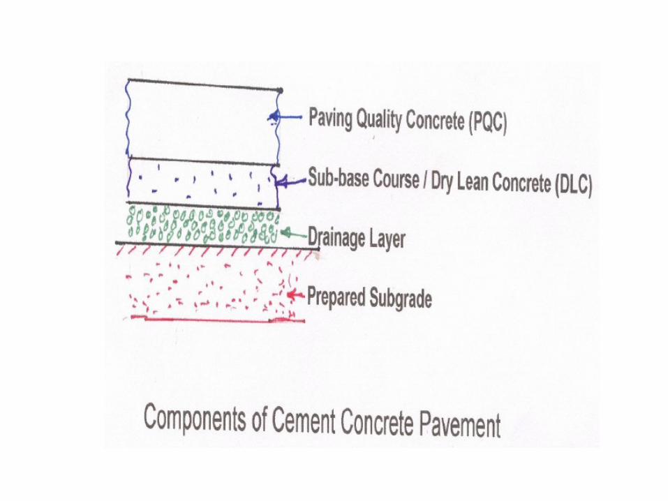
pavement components and their role
Design practice for flexible and rigid pavements, (IRC
methods only).
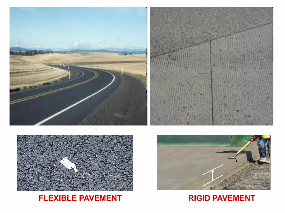
FLEXIBLE PAVEMENT RIGID PAVEMENT
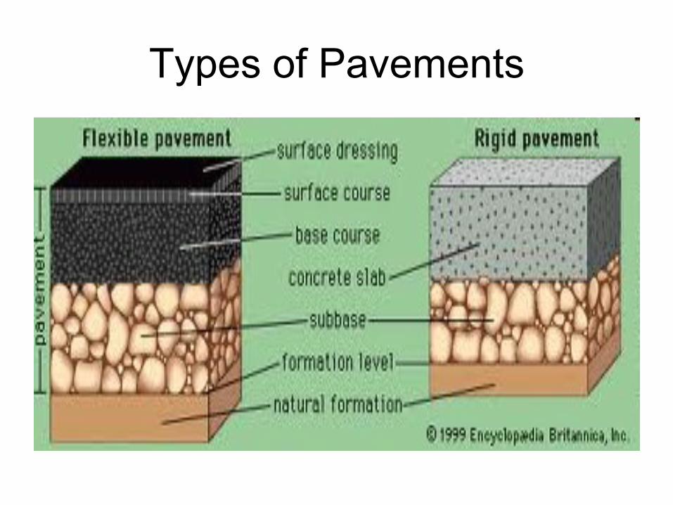
Types of Pavements
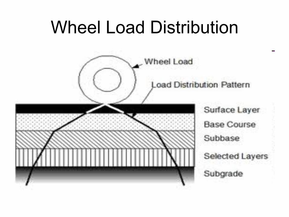
Wheel Load Distribution
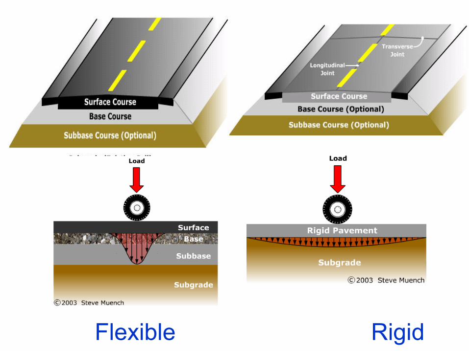
Flexible Rigid
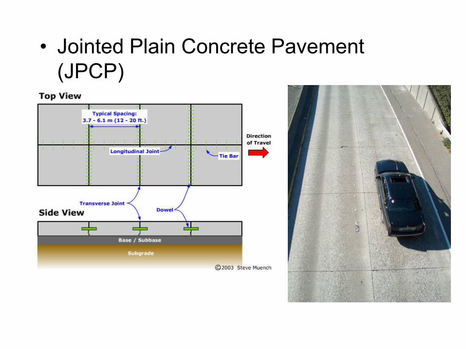
• Jointed Plain Concrete Pavement
(JPCP)
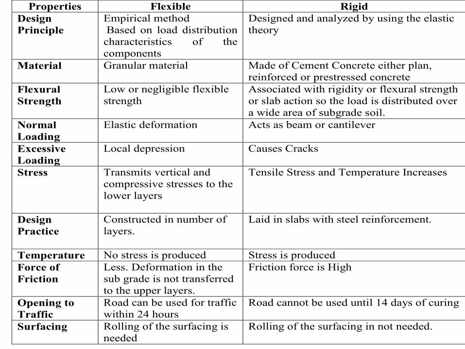
Properties Flexible Rigid
Design
Principle
Empirical method
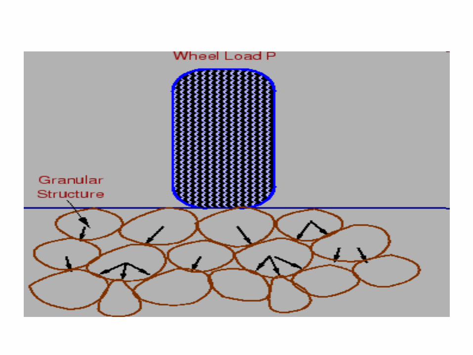
Based on load distribution
characteristics of the
components
Designed and analyzed by using the elastic
theory
Material Granular material Made of Cement Concrete either plan,
reinforced or prestressed concrete
Flexural
Strength
Low or negligible flexible
strength
Associated with rigidity or flexural strength
or slab action so the load is distributed over
a wide area of subgrade soil.
Normal
Loading
Elastic deformation Acts as beam or cantilever
Excessive
Loading
Local depression Causes Cracks
Stress Transmits vertical and
compressive stresses to the
lower layers
Tensile Stress and Temperature Increases
Design
Practice
Constructed in number of
layers.
Laid in slabs with steel reinforcement.
Temperature No stress is produced Stress is produced
Force of
Friction
Less. Deformation in the
sub grade is not transferred
to the upper layers.
Friction force is High
Opening to
Traffic
Road can be used for traffic
within 24 hours
Road cannot be used until 14 days of curing
Surfacing Rolling of the surfacing is
needed
Rolling of the surfacing in not needed.
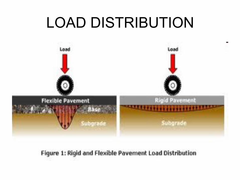
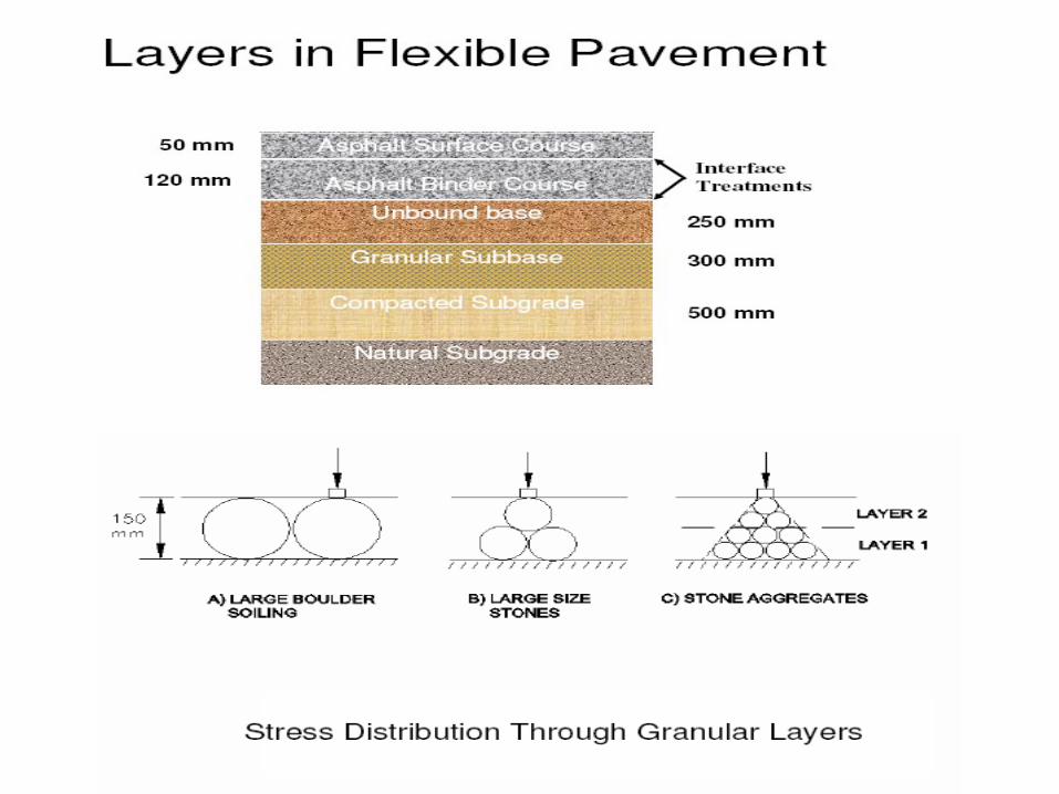
LOAD DISTRIBUTION
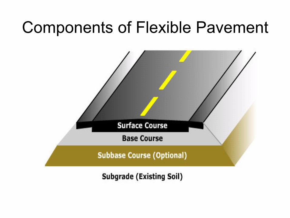
Components of Flexible Pavement
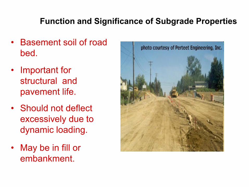
• Basement soil of road
bed.
• Important for
structural and
pavement life.
• Should not deflect
excessively due to
dynamic loading.
• May be in fill or
embankment.
Function and Significance of Subgrade Properties
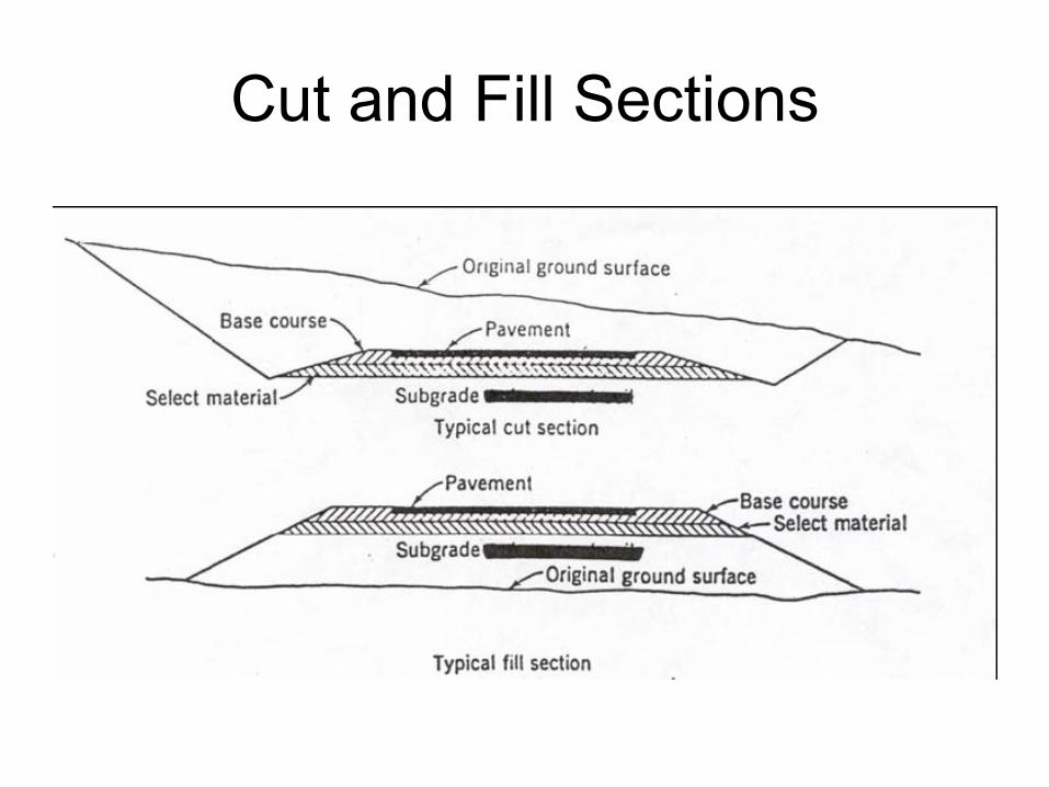
Cut and Fill Sections
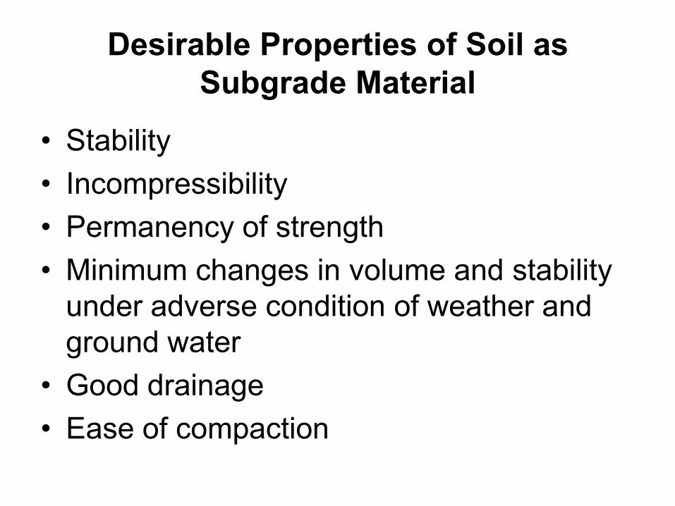
Desirable Properties of Soil as
Subgrade Material
• Stability
• Incompressibility
• Permanency of strength
• Minimum changes in volume and stability
under adverse condition of weather and
ground water
• Good drainage
• Ease of compaction
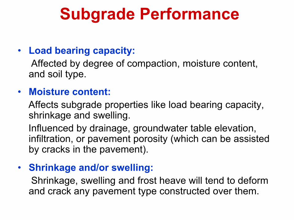
Subgrade Performance
• Load bearing capacity:
Affected by degree of compaction, moisture content, and soil type.
• Moisture content:
Affects subgrade properties like load bearing capacity, shrinkage and swelling.
Influenced by drainage, groundwater table elevation, infiltration, or pavement porosity (which can be assisted by cracks in the pavement).
• Shrinkage and/or swelling:
Shrinkage, swelling and frost heave will tend to deform and crack any pavement type constructed over them.
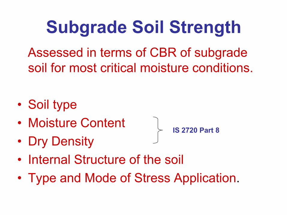
Subgrade Soil Strength
Assessed in terms of CBR of subgrade
soil for most critical moisture conditions.
• Soil type
• Moisture Content
• Dry Density
• Internal Structure of the soil
• Type and Mode of Stress Application.
IS 2720 Part 8
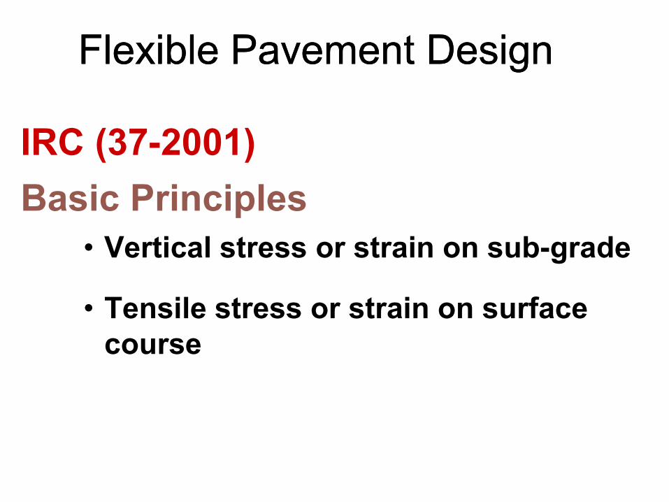
Flexible Pavement DesignFlexible Pavement Design
IRC (37-2001)
Basic Principles
• Vertical stress or strain on sub-grade
• Tensile stress or strain on surface
course
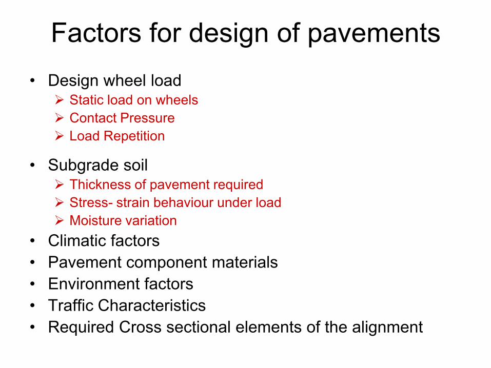
Factors for design of pavements
• Design wheel load Static load on wheels
Contact Pressure
Load Repetition
• Subgrade soil Thickness of pavement required
Stress- strain behaviour under load
Moisture variation
• Climatic factors
• Pavement component materials
• Environment factors
• Traffic Characteristics
• Required Cross sectional elements of the alignment
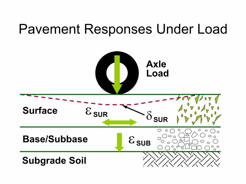
Subgrade Soil
Base/Subbase
Surface
d SUR
SUB
SUR
Axle Load
Pavement Responses Under Load
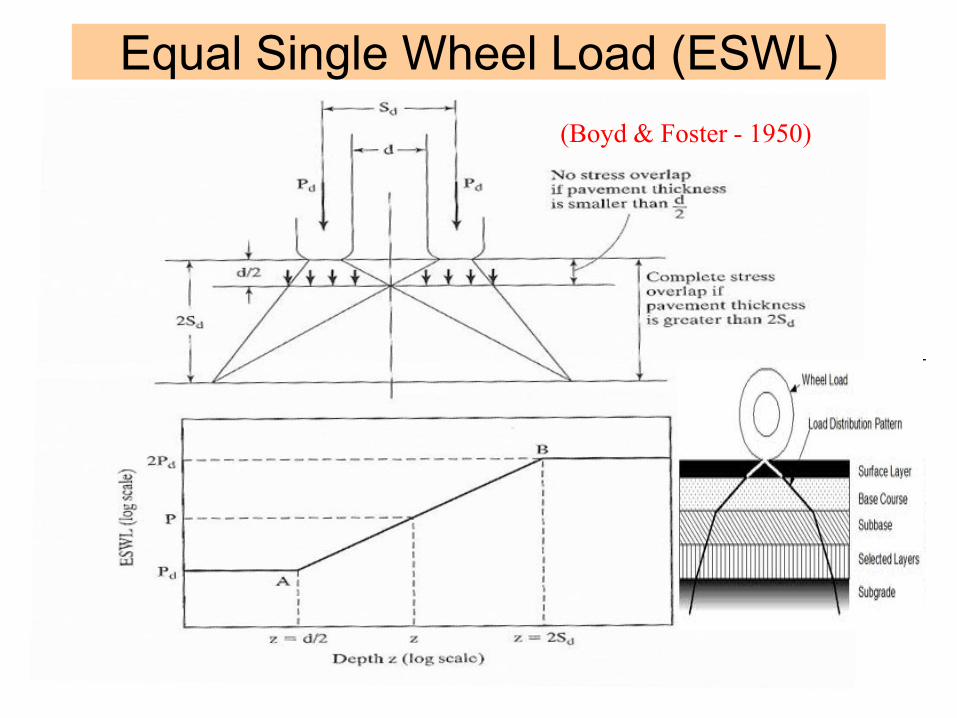
Equal Single Wheel Load (ESWL)
(Boyd & Foster - 1950)
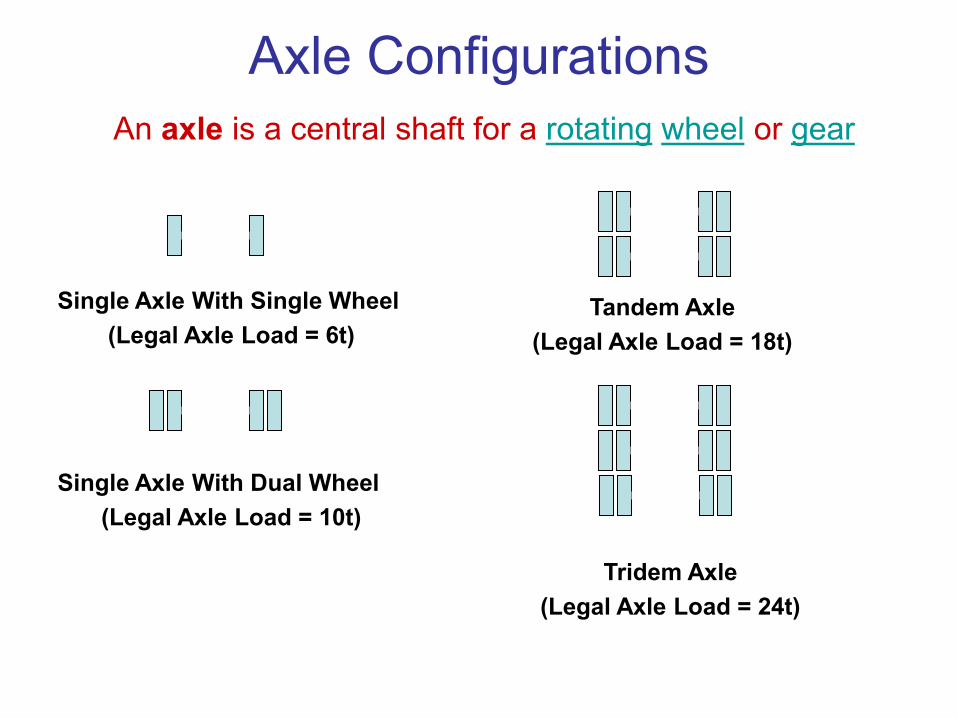
Axle Configurations
Single Axle With Single Wheel
(Legal Axle Load = 6t)
Single Axle With Dual Wheel
(Legal Axle Load = 10t)
Tandem Axle
(Legal Axle Load = 18t)
Tridem Axle
(Legal Axle Load = 24t)
An axle is a central shaft for a rotating wheel or gear
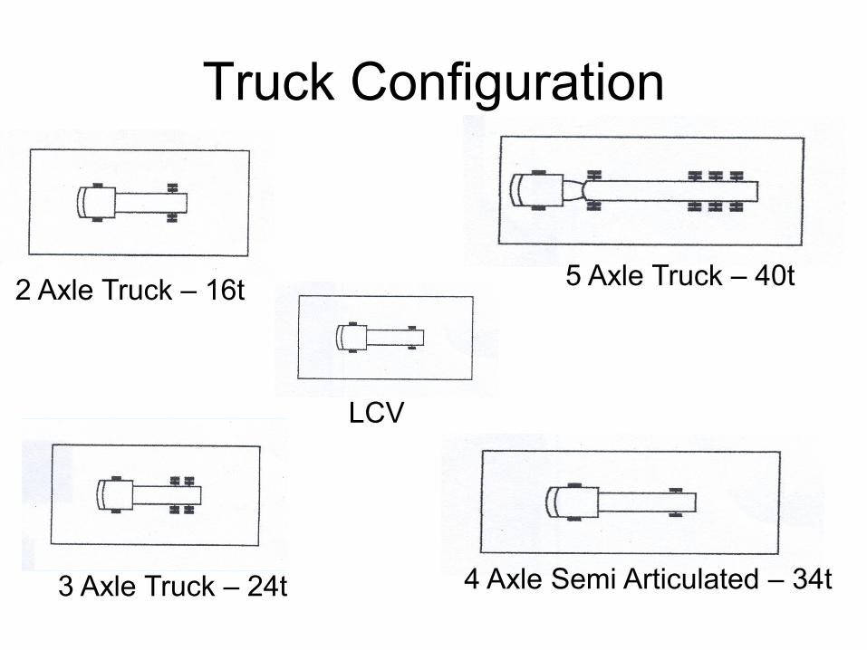
2 Axle Truck – 16t
3 Axle Truck – 24t
Truck Configuration
4 Axle Semi Articulated – 34t
5 Axle Truck – 40t
LCV
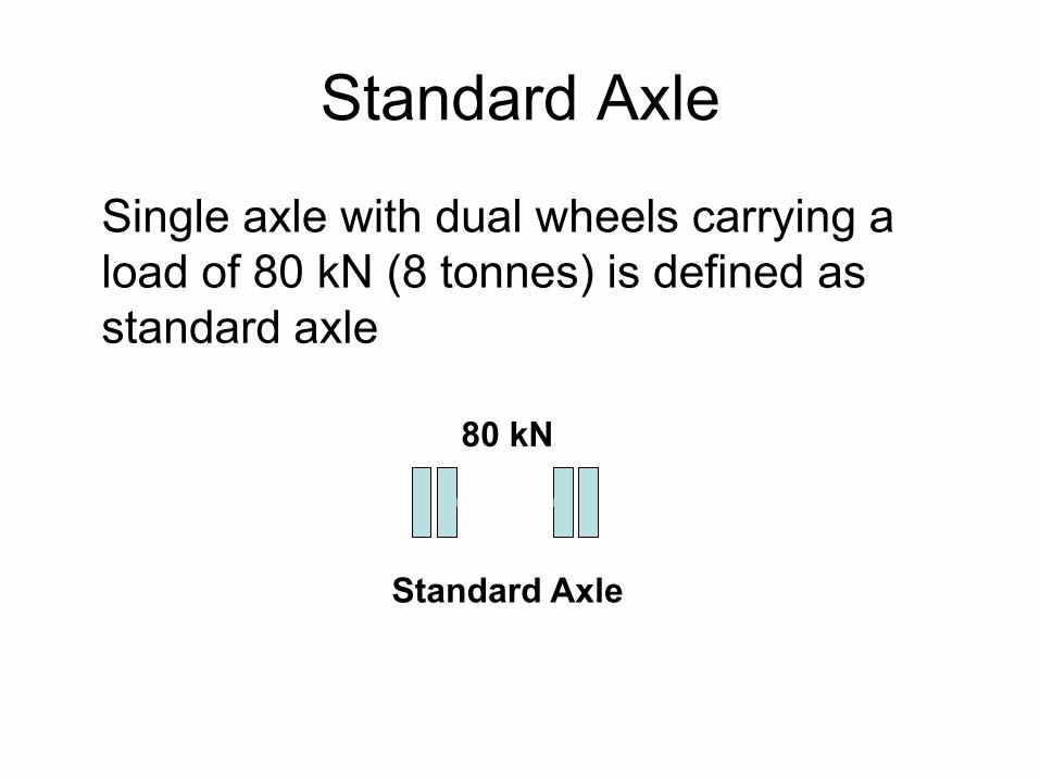
Standard Axle
Single axle with dual wheels carrying a
load of 80 kN (8 tonnes) is defined as
standard axle
80 kN
Standard Axle
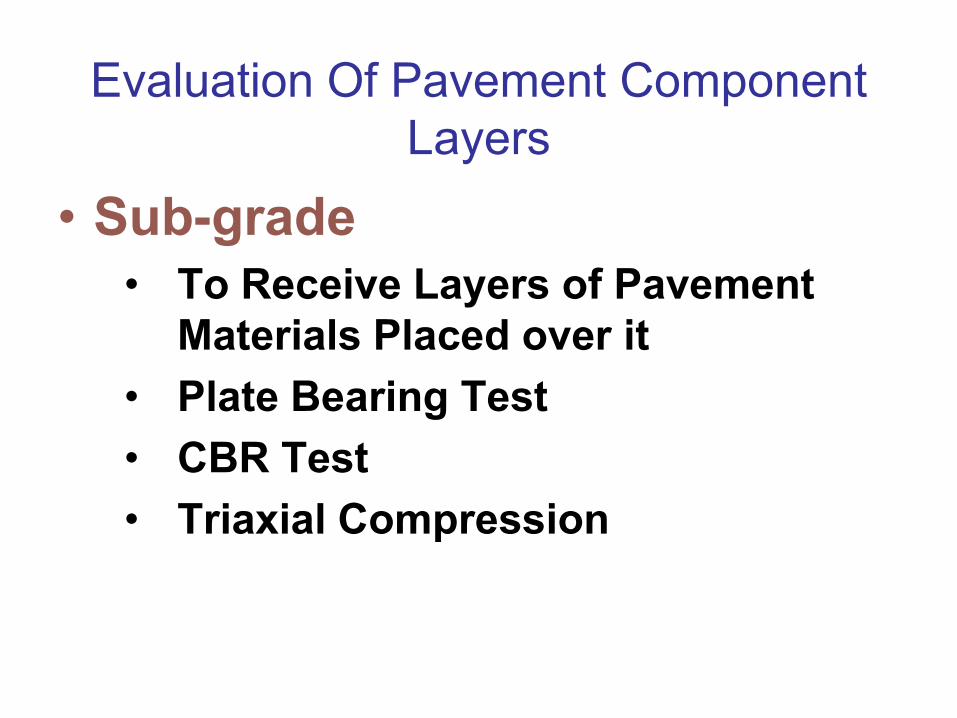
Evaluation Of Pavement Component
Layers
• Sub-grade
• To Receive Layers of Pavement
Materials Placed over it
• Plate Bearing Test
• CBR Test
• Triaxial Compression Test
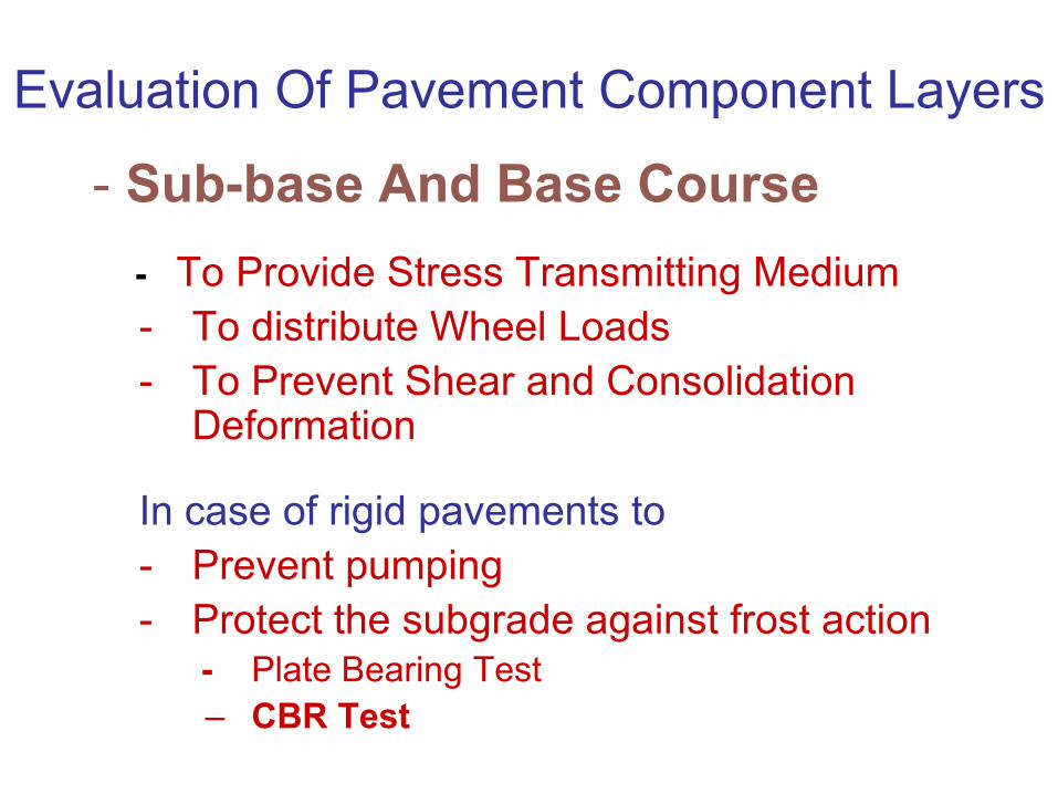
Evaluation Of Pavement Component Layers
- Sub-base And Base Course
- To Provide Stress Transmitting Medium
- To distribute Wheel Loads
- To Prevent Shear and Consolidation Deformation
In case of rigid pavements to
- Prevent pumping
- Protect the subgrade against frost action - Plate Bearing Test
– CBR Test
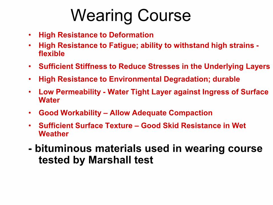
Wearing Course • High Resistance to Deformation
• High Resistance to Fatigue; ability to withstand high strains - flexible
• Sufficient Stiffness to Reduce Stresses in the Underlying Layers
• High Resistance to Environmental Degradation; durable
• Low Permeability - Water Tight Layer against Ingress of Surface Water
• Good Workability – Allow Adequate Compaction
• Sufficient Surface Texture – Good Skid Resistance in Wet Weather
- bituminous materials used in wearing course tested by Marshall test
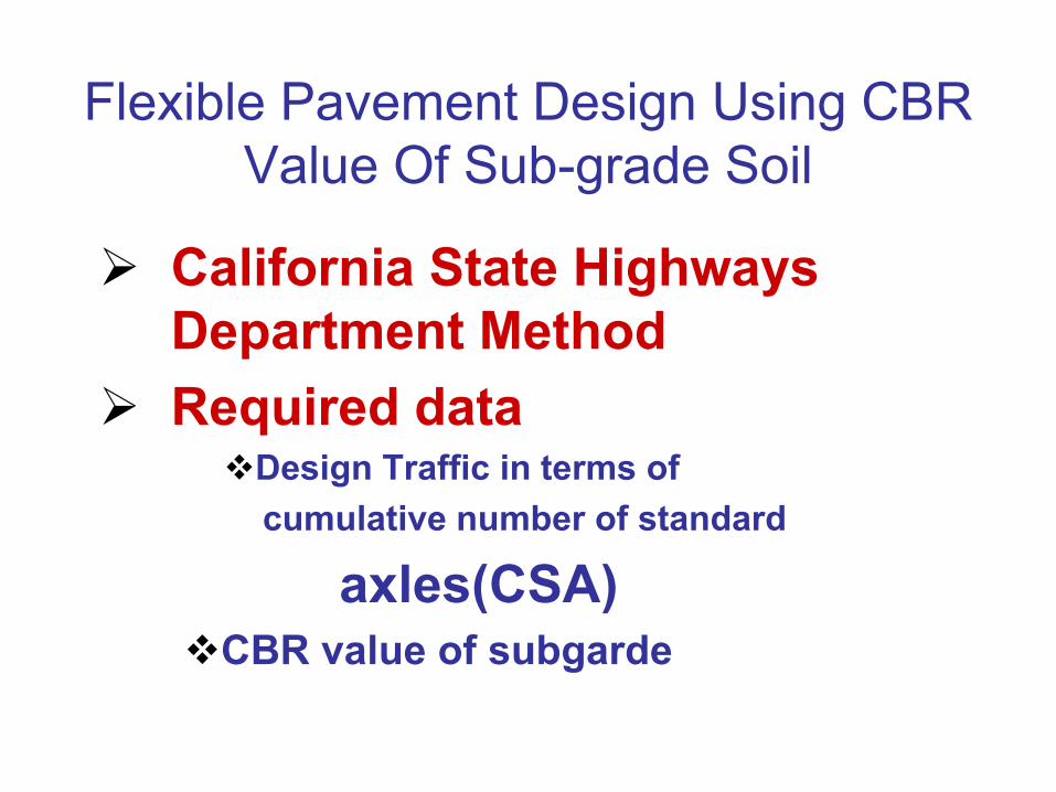
Flexible Pavement Design Using CBR
Value Of Sub-grade Soil
California State Highways
Department Method
Required data Design Traffic in terms of
cumulative number of standard
axles(CSA) CBR value of subgarde
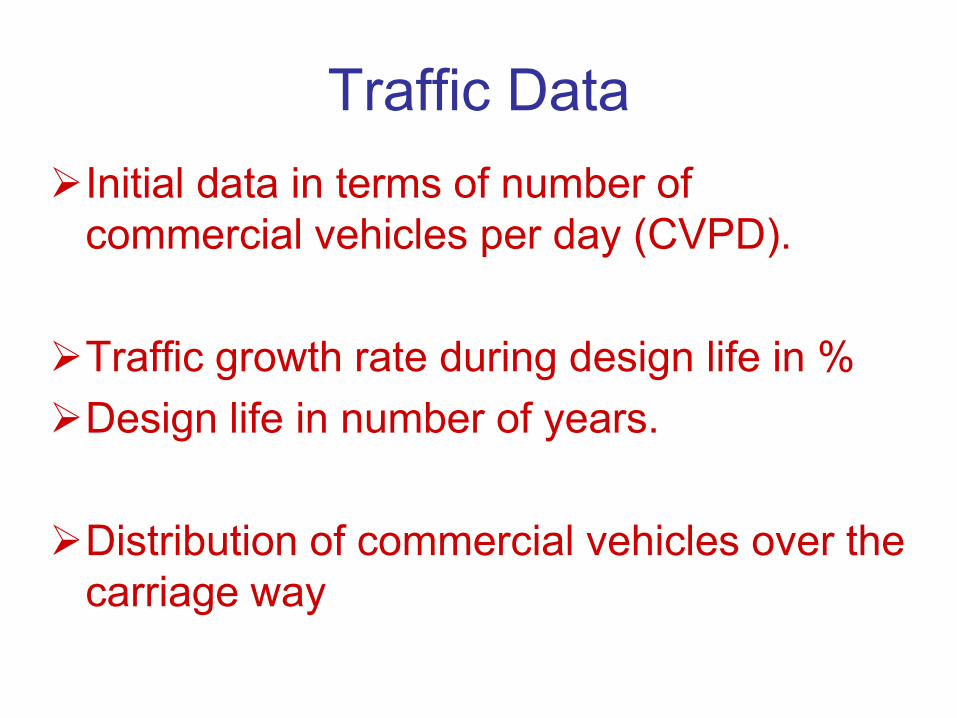
Traffic Data
Initial data in terms of number of
commercial vehicles per day (CVPD).
Traffic growth rate during design life in %
Design life in number of years.
Distribution of commercial vehicles over the
carriage way
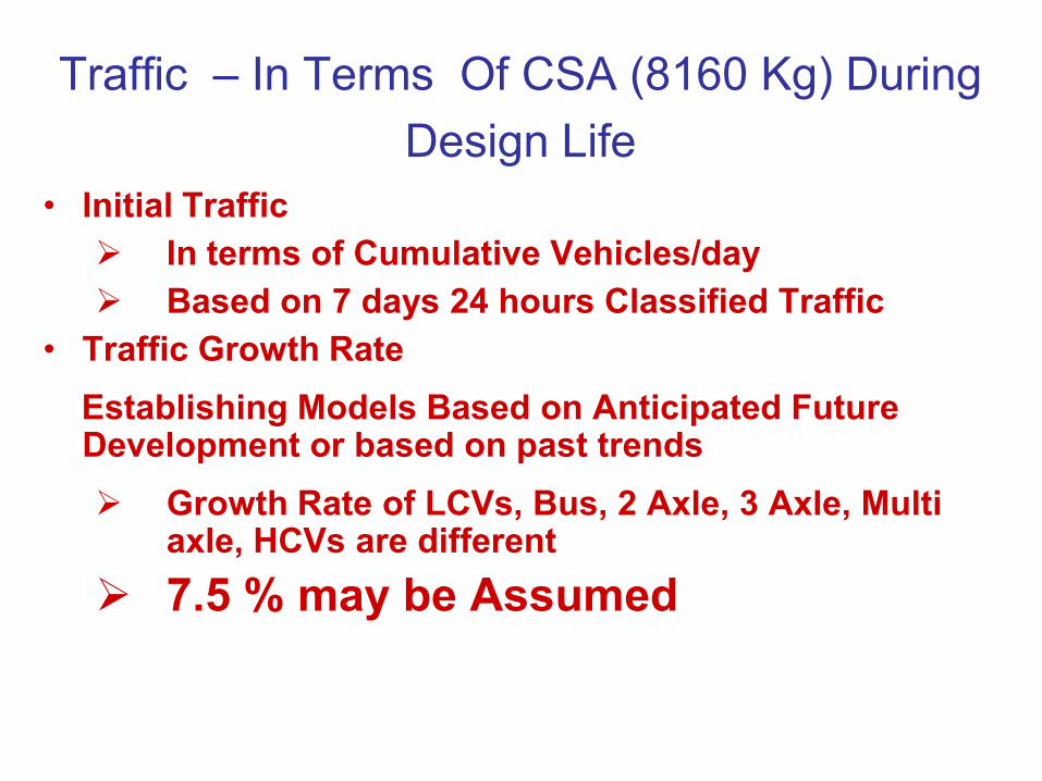
Traffic – In Terms Of CSA (8160 Kg) During
Design Life • Initial Traffic
In terms of Cumulative Vehicles/day
Based on 7 days 24 hours Classified Traffic
• Traffic Growth Rate
Establishing Models Based on Anticipated Future Development or based on past trends
Growth Rate of LCVs, Bus, 2 Axle, 3 Axle, Multi axle, HCVs are different
7.5 % may be Assumed
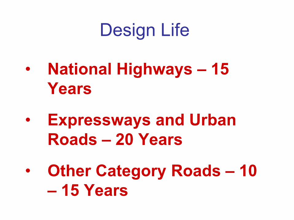
Design Life
• National Highways – 15
Years
• Expressways and Urban
Roads – 20 Years
• Other Category Roads – 10
– 15 Years
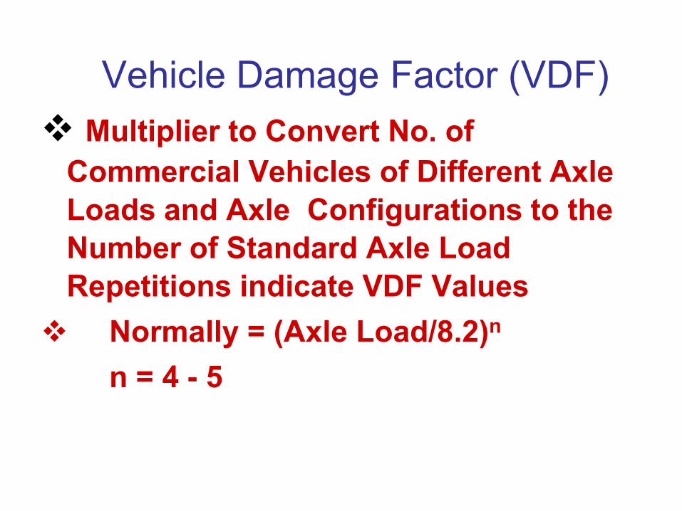
Vehicle Damage Factor (VDF)
Multiplier to Convert No. of
Commercial Vehicles of Different Axle
Loads and Axle Configurations to the
Number of Standard Axle Load
Repetitions indicate VDF Values
Normally = (Axle Load/8.2)n
n = 4 - 5
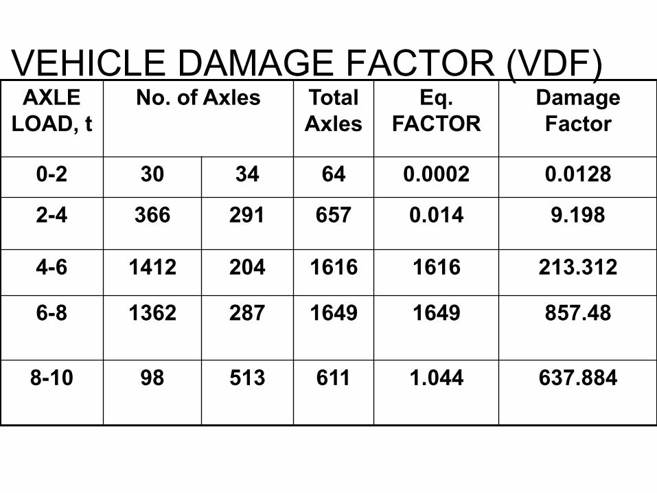
VEHICLE DAMAGE FACTOR (VDF) AXLE
LOAD, t
No. of Axles Total
Axles
Eq.
FACTOR
Damage
Factor
0-2 30 34 64 0.0002 0.0128
2-4 366 291 657 0.014 9.198
4-6 1412 204 1616 1616 213.312
6-8 1362 287 1649 1649 857.48
8-10 98 513 611 1.044 637.884
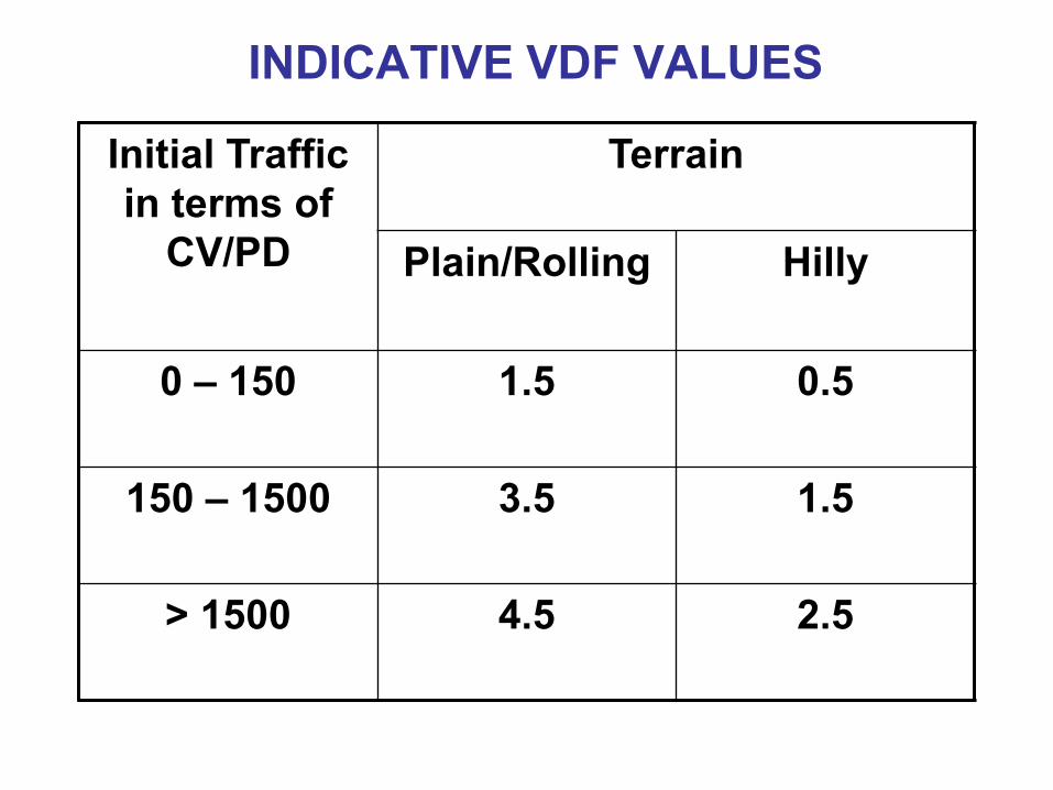
INDICATIVE VDF VALUES
Initial Traffic
in terms of
CV/PD
Terrain
Plain/Rolling Hilly
0 – 150 1.5 0.5
150 – 1500 3.5 1.5
> 1500 4.5 2.5
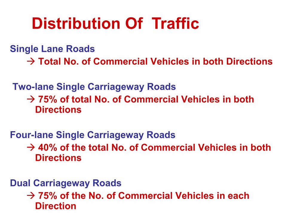
Single Lane Roads
Total No. of Commercial Vehicles in both Directions
Two-lane Single Carriageway Roads
75% of total No. of Commercial Vehicles in both Directions
Four-lane Single Carriageway Roads
40% of the total No. of Commercial Vehicles in both Directions
Dual Carriageway Roads
75% of the No. of Commercial Vehicles in each Direction
Distribution Of Traffic
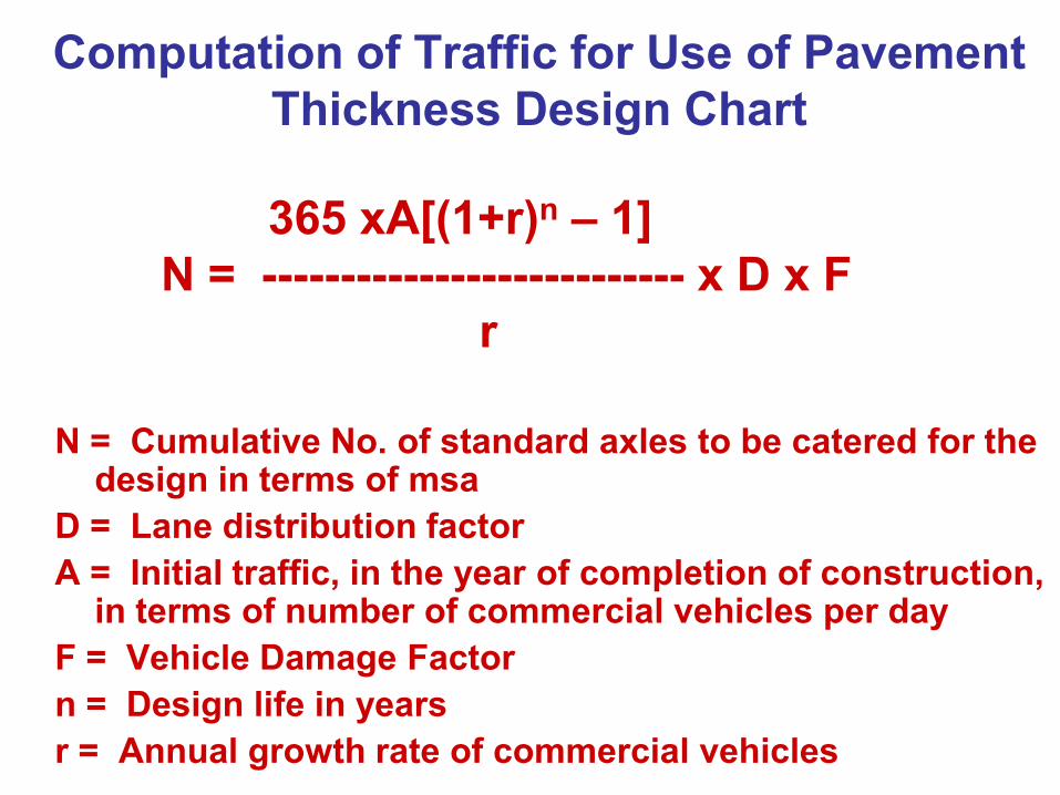
Computation of Traffic for Use of Pavement
Thickness Design Chart
365 xA[(1+r)n – 1]
N = --------------------------- x D x F
r
N = Cumulative No. of standard axles to be catered for the
design in terms of msa
D = Lane distribution factor
A = Initial traffic, in the year of completion of construction, in terms of number of commercial vehicles per day
F = Vehicle Damage Factor
n = Design life in years
r = Annual growth rate of commercial vehicles
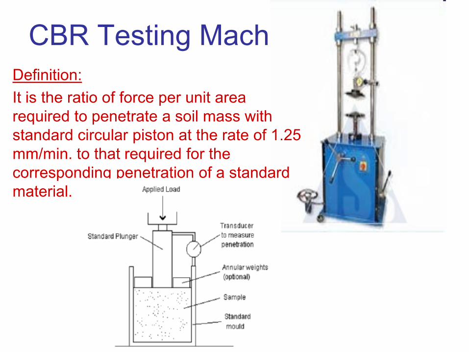
CBR Testing Machine
Definition:
It is the ratio of force per unit area
required to penetrate a soil mass with
standard circular piston at the rate of 1.25
mm/min. to that required for the
corresponding penetration of a standard
material.
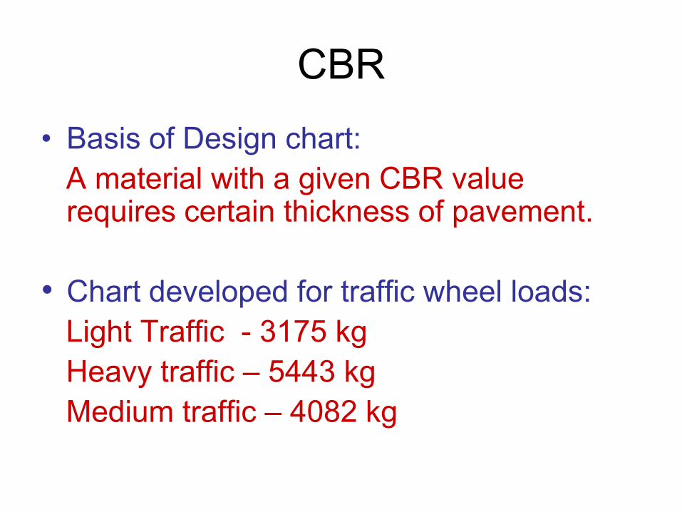
CBR
• Basis of Design chart:
A material with a given CBR value requires certain thickness of pavement.
• Chart developed for traffic wheel loads:
Light Traffic - 3175 kg
Heavy traffic – 5443 kg
Medium traffic – 4082 kg
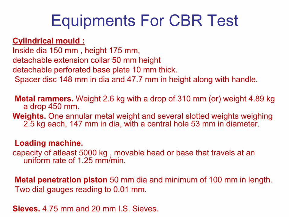
Equipments For CBR Test Cylindrical mould :
Inside dia 150 mm , height 175 mm,
detachable extension collar 50 mm height
detachable perforated base plate 10 mm thick.
Spacer disc 148 mm in dia and 47.7 mm in height along with handle.
Metal rammers. Weight 2.6 kg with a drop of 310 mm (or) weight 4.89 kg a drop 450 mm.
Weights. One annular metal weight and several slotted weights weighing 2.5 kg each, 147 mm in dia, with a central hole 53 mm in diameter.
Loading machine.
capacity of atleast 5000 kg , movable head or base that travels at an uniform rate of 1.25 mm/min.
Metal penetration piston 50 mm dia and minimum of 100 mm in length.
Two dial gauges reading to 0.01 mm.
Sieves. 4.75 mm and 20 mm I.S. Sieves.
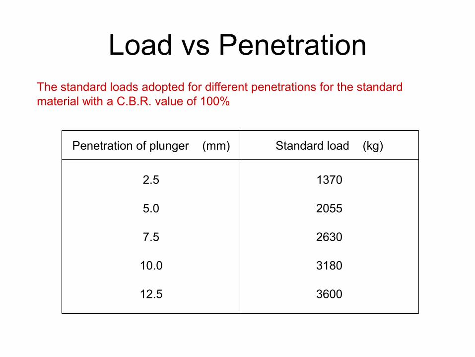
Load vs Penetration
The standard loads adopted for different penetrations for the standard
material with a C.B.R. value of 100%
Penetration of plunger (mm) Standard load (kg)
2.5
5.0
7.5
10.0
12.5
1370
2055
2630
3180
3600
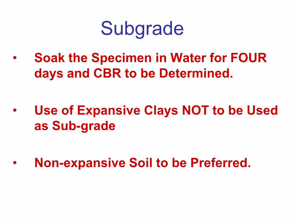
Subgrade
• Soak the Specimen in Water for FOUR
days and CBR to be Determined.
• Use of Expansive Clays NOT to be Used
as Sub-grade
• Non-expansive Soil to be Preferred.

Subgrade • Subgrade to be Well Compacted to Utilize its Full
Strength
• Top 500 mm to be Compacted to 97% of MDD
(Modified Proctor).
• Material Should Have a Dry Density of 1.75 gm/cc.
• CBR to be at Critical Moisture Content and Field
Density.
• Strength – Lab. CBR on Remoulded Specimens
and NOT Field CBR
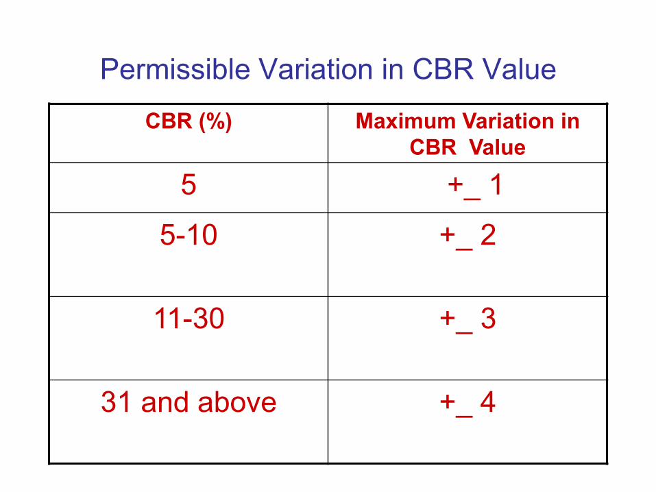
Permissible Variation in CBR Value
CBR (%) Maximum Variation in
CBR Value
5 +_ 1
5-10 +_ 2
11-30 +_ 3
31 and above +_ 4
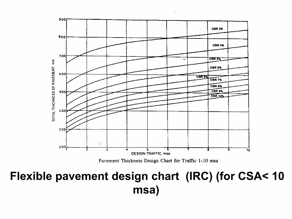
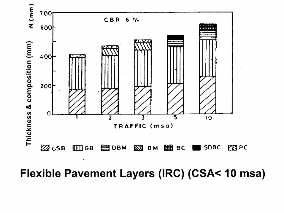
Flexible pavement design chart (IRC) (for CSA< 10
msa)
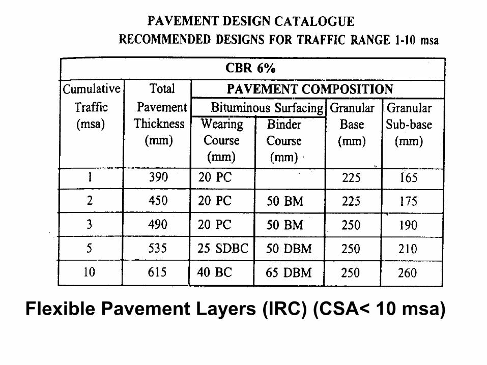
Flexible Pavement Layers (IRC) (CSA< 10 msa)
Th
ickn
ess
& c
om
po
sit
ion
(m
m)
Flexible Pavement Layers (IRC) (CSA< 10 msa)
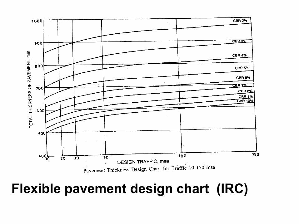
Flexible pavement design chart (IRC)
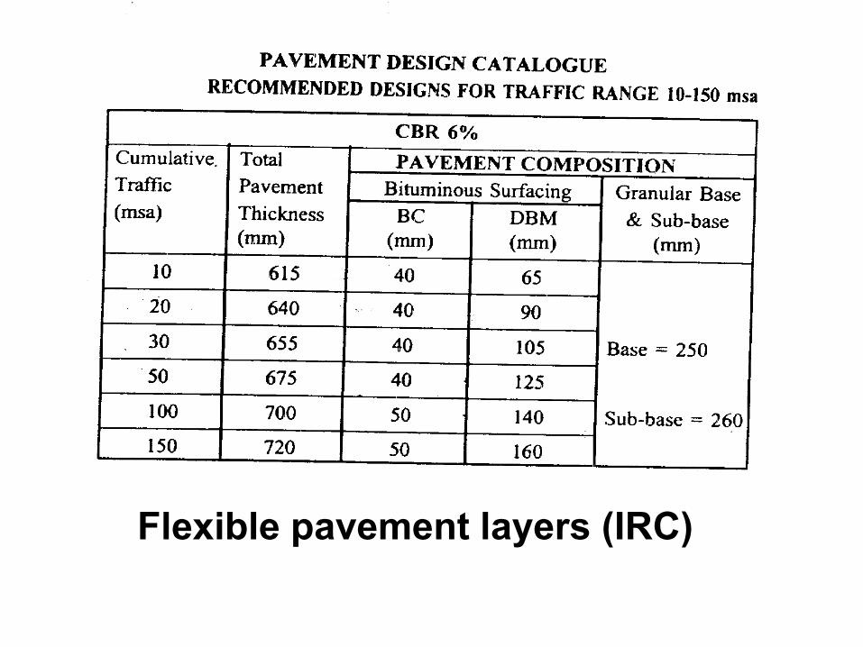
Flexible pavement layers (IRC)
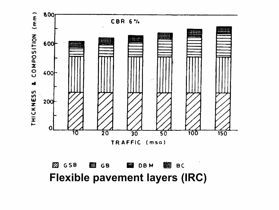
Flexible pavement layers (IRC)
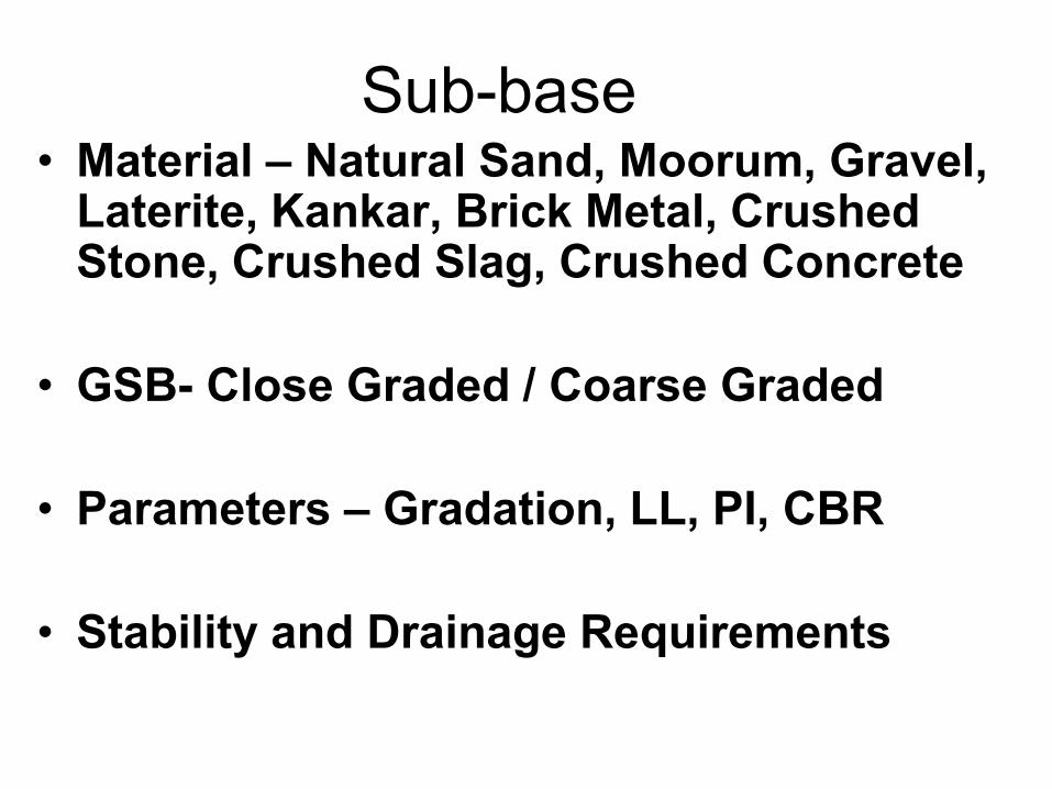
Sub-base • Material – Natural Sand, Moorum, Gravel,
Laterite, Kankar, Brick Metal, Crushed Stone, Crushed Slag, Crushed Concrete
• GSB- Close Graded / Coarse Graded
• Parameters – Gradation, LL, PI, CBR
• Stability and Drainage Requirements
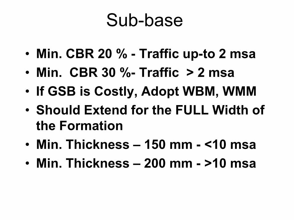
Sub-base
• Min. CBR 20 % - Traffic up-to 2 msa
• Min. CBR 30 %- Traffic > 2 msa
• If GSB is Costly, Adopt WBM, WMM
• Should Extend for the FULL Width of
the Formation
• Min. Thickness – 150 mm - <10 msa
• Min. Thickness – 200 mm - >10 msa
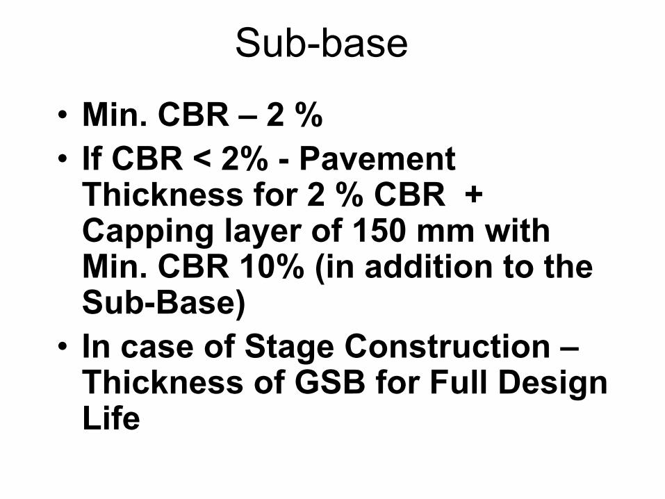
Sub-base
• Min. CBR – 2 %
• If CBR < 2% - Pavement Thickness for 2 % CBR + Capping layer of 150 mm with Min. CBR 10% (in addition to the Sub-Base)
• In case of Stage Construction – Thickness of GSB for Full Design Life
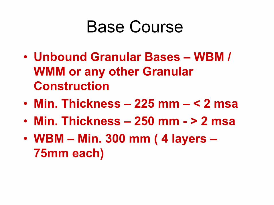
Base Course
• Unbound Granular Bases – WBM /
WMM or any other Granular
Construction
• Min. Thickness – 225 mm – < 2 msa
• Min. Thickness – 250 mm - > 2 msa
• WBM – Min. 300 mm ( 4 layers –
75mm each)
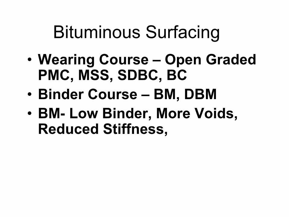
Bituminous Surfacing
• Wearing Course – Open Graded PMC, MSS, SDBC, BC
• Binder Course – BM, DBM
• BM- Low Binder, More Voids, Reduced Stiffness,
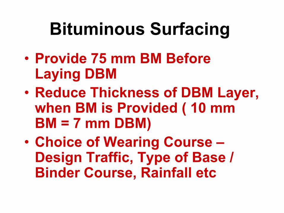
Bituminous Surfacing
• Provide 75 mm BM Before Laying DBM
• Reduce Thickness of DBM Layer, when BM is Provided ( 10 mm BM = 7 mm DBM)
• Choice of Wearing Course – Design Traffic, Type of Base / Binder Course, Rainfall etc
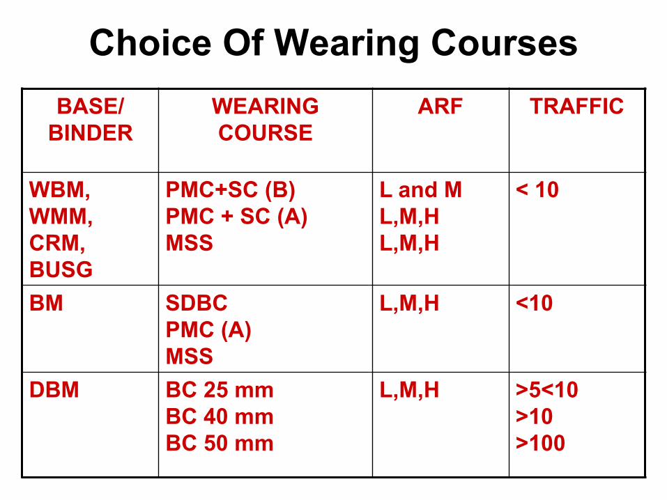
Choice Of Wearing Courses
BASE/
BINDER
WEARING
COURSE
ARF TRAFFIC
WBM,
WMM,
CRM,
BUSG
PMC+SC (B)
PMC + SC (A)
MSS
L and M
L,M,H
L,M,H
< 10
BM SDBC
PMC (A)
MSS
L,M,H <10
DBM BC 25 mm
BC 40 mm
BC 50 mm
L,M,H
>5<10
>10
>100
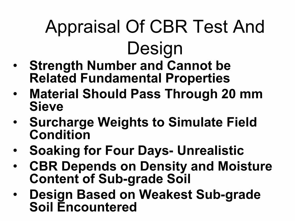
Appraisal Of CBR Test And
Design • Strength Number and Cannot be
Related Fundamental Properties
• Material Should Pass Through 20 mm Sieve
• Surcharge Weights to Simulate Field Condition
• Soaking for Four Days- Unrealistic
• CBR Depends on Density and Moisture Content of Sub-grade Soil
• Design Based on Weakest Sub-grade Soil Encountered

Example Of Pavement
Design For A New
Bypass
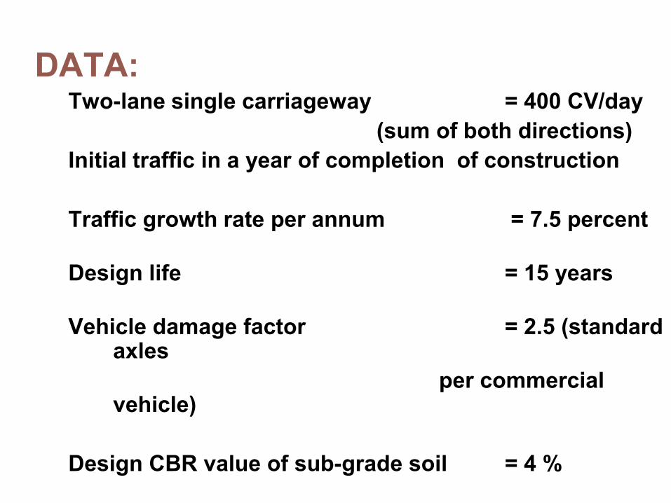
DATA: Two-lane single carriageway = 400 CV/day
(sum of both directions)
Initial traffic in a year of completion of construction
Traffic growth rate per annum = 7.5 percent
Design life = 15 years
Vehicle damage factor = 2.5 (standard axles
per commercial vehicle)
Design CBR value of sub-grade soil = 4 %
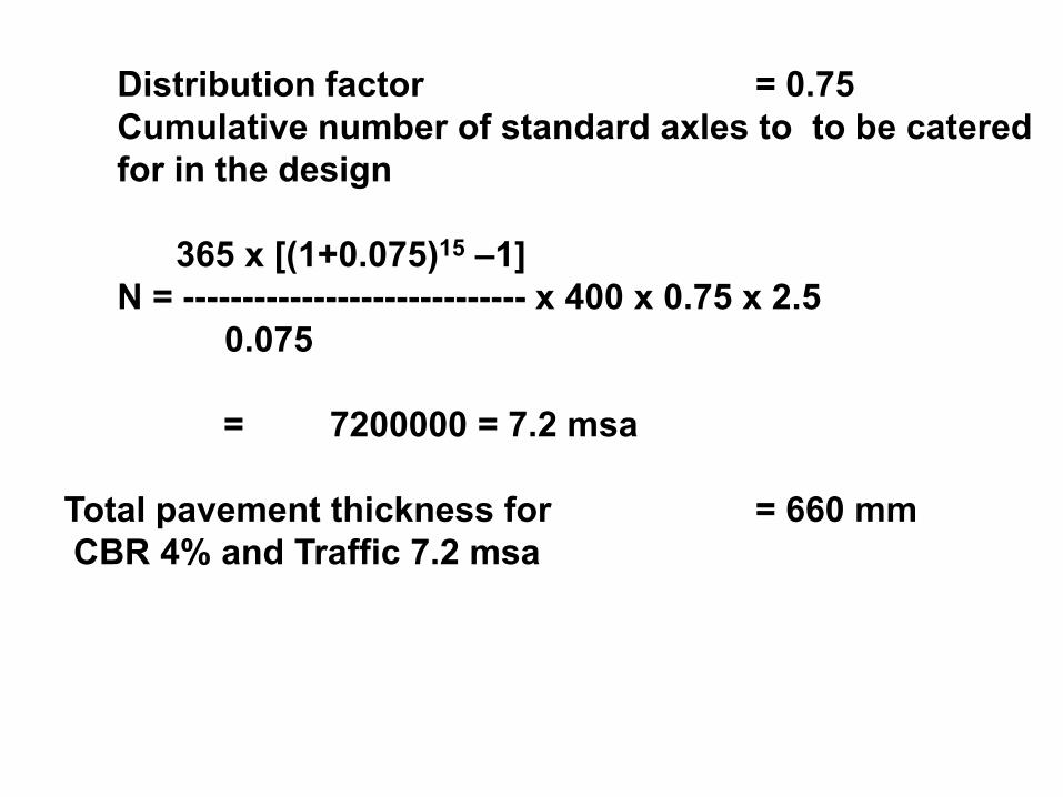
Distribution factor = 0.75
Cumulative number of standard axles to to be catered
for in the design
365 x [(1+0.075)15 –1]
N = ----------------------------- x 400 x 0.75 x 2.5
0.075
= 7200000 = 7.2 msa
Total pavement thickness for = 660 mm
CBR 4% and Traffic 7.2 msa
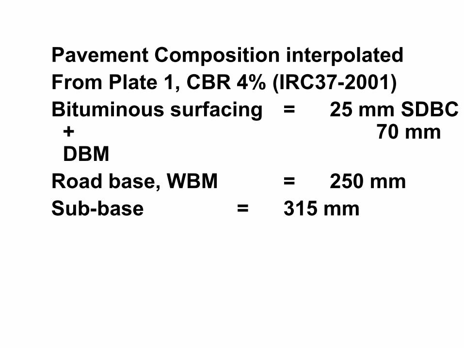
Pavement Composition interpolated
From Plate 1, CBR 4% (IRC37-2001)
Bituminous surfacing = 25 mm SDBC + 70 mm DBM
Road base, WBM = 250 mm
Sub-base = 315 mm
Example Of Pavement
Design For Widening An
Existing 2-lane NH To 4-
lane Divided Road
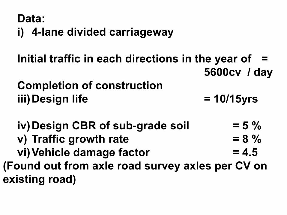
Data:
i) 4-lane divided carriageway
Initial traffic in each directions in the year of =
5600cv / day
Completion of construction
iii) Design life = 10/15yrs
iv) Design CBR of sub-grade soil = 5 %
v) Traffic growth rate = 8 %
vi) Vehicle damage factor = 4.5
(Found out from axle road survey axles per CV on
existing road)
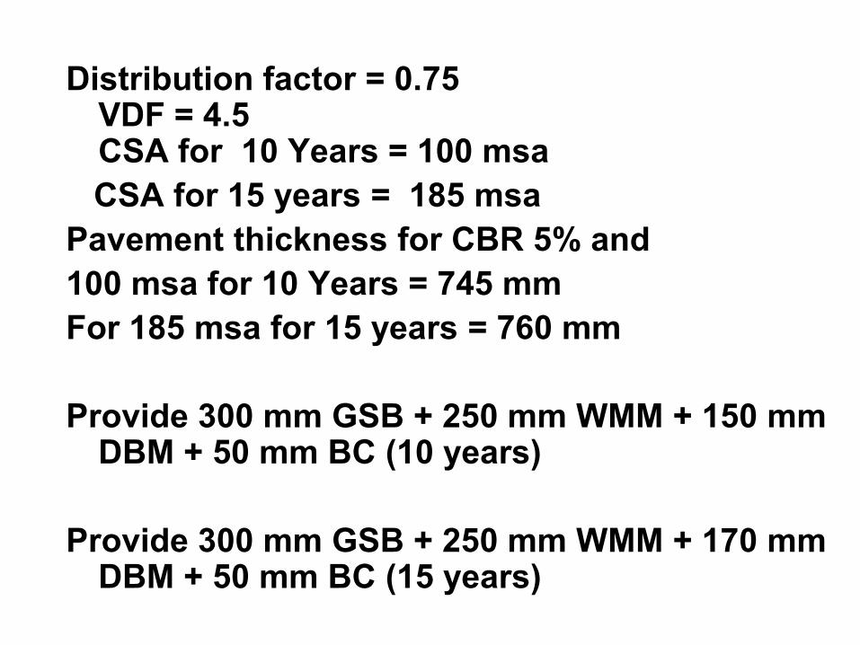
Distribution factor = 0.75 VDF = 4.5 CSA for 10 Years = 100 msa
CSA for 15 years = 185 msa
Pavement thickness for CBR 5% and
100 msa for 10 Years = 745 mm
For 185 msa for 15 years = 760 mm
Provide 300 mm GSB + 250 mm WMM + 150 mm DBM + 50 mm BC (10 years)
Provide 300 mm GSB + 250 mm WMM + 170 mm DBM + 50 mm BC (15 years)
References
1.Yoder and Witczak “Principles of Pavement Design”
John Wiley and Sons , second edition
2.IRC :37-2001, Guidelines of Design of
Flexible Pavements”
3.IRC:81 - 1997 “Tentative Guidelines for Strengthening
of Flexible Road Pavements Using Benkelman Beam
Deflection Technique