Design, Fabrication and Startup of an Offshore … Annual Convention, March 8-11, 2009 Gas...
15
88 th Annual Convention, March 8-11, 2009 Gas Processors Association Page 1 Design, Fabrication and Startup of an Offshore Membrane CO 2 Removal System William Echt and Peter Meister UOP LLC, A Honeywell Company Des Plaines, Illinois, USA © 2009 UOP LLC All Rights Reserved ABSTRACT As the world searches for more energy in more remote locations, natural gas reserves that would have been marginal or unprofitable years ago are now being developed. Many of these reserves are offshore and contain large amounts of carbon dioxide. Pipelines and compression to bring the gas to shore are expensive, so at least partial offshore gas conditioning makes economic sense. This paper presents the results of a project to bring offshore natural gas reserves into production for delivery in Asia. The design of the UOP Separex™ membrane system for CO 2 removal is reviewed, showing key considerations that impact the project economics. Of particular interest are the integration of the mercury removal and natural gas liquids (NGL) recovery systems with the CO 2 removal system and the comparison of the chosen pretreatment design to an alternate scheme that uses chilling for pretreatment. The method of constructing the offshore platform is also presented and important fabrication steps are highlighted. Finally, a review of the platform startup is presented with initial and current operating data. UOP worked closely with our customer in all phases of the project. The optimized design has proven to meet performance expectations. The UOP system is operating since March 2007 without significant membrane replacement.
Transcript of Design, Fabrication and Startup of an Offshore … Annual Convention, March 8-11, 2009 Gas...

88th Annual Convention, March 8-11, 2009 Gas Processors Association
Page 1
Design, Fabrication and Startup of an Offshore Membrane CO2 Removal System
William Echt and
Peter Meister UOP LLC, A Honeywell Company
Des Plaines, Illinois, USA © 2009 UOP LLC All Rights Reserved
ABSTRACT
As the world searches for more energy in more remote locations, natural gas reserves that would have been marginal or unprofitable years ago are now being developed. Many of these reserves are offshore and contain large amounts of carbon dioxide. Pipelines and compression to bring the gas to shore are expensive, so at least partial offshore gas conditioning makes economic sense. This paper presents the results of a project to bring offshore natural gas reserves into production for delivery in Asia. The design of the UOP Separex™ membrane system for CO2 removal is reviewed, showing key considerations that impact the project economics. Of particular interest are the integration of the mercury removal and natural gas liquids (NGL) recovery systems with the CO2 removal system and the comparison of the chosen pretreatment design to an alternate scheme that uses chilling for pretreatment. The method of constructing the offshore platform is also presented and important fabrication steps are highlighted. Finally, a review of the platform startup is presented with initial and current operating data. UOP worked closely with our customer in all phases of the project. The optimized design has proven to meet performance expectations. The UOP system is operating since March 2007 without significant membrane replacement.

88th Annual Convention, March 8-11, 2009 Gas Processors Association
Page 2
Introduction In the summer of 2002, UOP was approached to provide budgetary membrane system design for CO2 removal to be installed on an offshore gas processing platform in Asian waters. Following comprehensive engineering and cost evaluation, UOP was awarded the supply of a UOP MemGuard™ pretreatment system and downstream Separex membrane system in the fall of 2003. The platform was completed in the fabrication yard in the winter of 2005 and gas first entered the facility in spring 2007. This paper presents the results and lessons-learned from design, fabrication, installation and start-up of this large offshore facility. As the supplier of the key process technology for the new platform, UOP was involved in all phases of the project. This paper highlights and discusses design features that are of general interest as well as those specific to the Separex membrane unit for CO2 removal. Project Definition Armed with reservoir information from existing producing wells and the results of initial choke flows from newly drilled wells, the production company established a plan to install additional oil and gas processing capacity. Fields adjacent to existing offshore facilities contained significant oil reserves, but the associated gas had CO2 levels ranging from 26 to 55%. By blending producing oil wells with lower-CO2 gas wells, it was calculated that feed gas to the new processing platform could be maintained at a maximum 44.5% CO2. Export gas from the platform had to be dehydrated and meet a pipeline specification of 8% CO2. The export gas capacity was required to be 320 MMSCFD minimum, with a design capacity of 350 MMSCFD, which translates to a feed gas flow rate of 590-680 MMSCFD, depending upon the actual CO2 content in the feed gas and the mode of operation of the membrane unit. Feed gas definition and key product gas specifications are shown in Tables 1 and 2, respectively.
Table 1 – Feed Gas Definition
Flow (MMSCFD) Maximum 680.0 Pressure (kPag) 4000 Temperature (°C) 47 Composition mole % Carbon Dioxide 44.49 Methane 46.63 Ethane 4.18 Propane 1.94 C4+ 2.76 Nitrogen 0.84 Water Saturated Mercury 40 µg/Sm3
88th Annual Convention, March 8-11, 2009 Gas Processors Association
Page 3
Table 2 – Product Gas Specification
Flow (MMSCFD) Minimum 320 Composition Specifications Carbon Dioxide < 8.00 mole% Water <5 lb/MMSCF Mercury <5 µg/Sm3
Process Scheme Selection
In conjunction with an engineering company retained to design platforms and prepare cost estimates, the producer performed front end engineering design work on several process scheme alternatives. The evaluations were based on a fundamental decision to integrate the process equipment into the platform decks. This construction method differs from the modular method whereby all the equipment is first installed on steel frames, piped to the edge of the module and where the pre-fabricated modules are then pieced together on platform jacket supports. Integrated platform construction is generally considered to have less structural steel and less overall weight compared to modular installations. Each process scheme alternative was evaluated in terms of process performance, cost, plot space and weight and even included the optimization of the supporting platform jacket design for each process scheme. Integration of NGL Recovery with CO2 Removal In particular, the location of NGL recovery equipment either upstream or downstream of the CO2 removal unit was examined. Condensed NGL were to be stabilized and mixed with produced oil to increase revenue. The location of NGL recovery within the gas processing scheme was a critical design parameter that impacted platform size, weight and cost. Figures 1 and 2 show the block flow diagrams for two key process schemes that were most closely compared.

88th Annual Convention, March 8-11, 2009 Gas Processors Association
Page 4
Figure 1 – Cold System
(Future)Feed
Compression and Cooling
DehydrationMercury Removal
And Pretreatment
Membrane Separation
Export Compression and Cooling
Downstream Chilling /
NGL Recovery
Feed
ExportPermeate
NGL NGL Stabilization
Compressed Overhead
Vapors
Figure 2 – Warm System
The “Cold System” requires upstream dehydration as the feed gas will be chilled below the hydrate formation temperature. After mercury removal, the gas is chilled to accomplish two objectives: (a) NGL recovery and (b) removal of heavy hydrocarbons and aromatic compounds that, when condensed into liquids, damage the downstream membrane elements. Downstream of chilling, membranes remove the CO2 to specification. Because of the very low operating temperature, light hydrocarbon liquids are condensed on the membrane surface. All hydrocarbon liquids are routed to the stabilizer and the overhead from the stabilizer is compressed and sent to the Export Gas compressors. The Cold System uses a propane refrigeration system to chill the gas for pretreatment and NGL recovery. The membrane operates cold and extensive cross exchange is used to reduce the duty on the propane system.

88th Annual Convention, March 8-11, 2009 Gas Processors Association
Page 5
The “Warm System” first uses cross exchange to condense a small amount of water and hydrocarbons from the feed stream before entering a MemGuard pretreatment system.1 This pretreatment system, based on temperature-swing adsorption (TSA), simultaneously removes water, heavy hydrocarbons and mercury from the feed gas. The regenerative system operates much like a molecular sieve dehydrator, but uses proprietary UOP adsorbents to remove hydrocarbons and elemental mercury together with the water. After pretreatment the gas is heated using heat transfer fluid supplied from the permeate compressor waste heat recovery system. The Separex membranes, which operate close to ambient temperature, then remove the CO2 to specification. The product gas is then chilled using propane refrigeration to recover NGL. In both cases, the membranes utilize a two-stage configuration in order to obtain high hydrocarbon recovery (minimum 95%) while removing more than 87% of the CO2 from the feed stream. In a two-stage system, the permeate stream from the primary membranes is compressed and processed in the second stage membranes to improve hydrocarbon recovery.2 The Warm System uses much less refrigeration chilling the membrane residue stream when compared to the Cold System which chills the entire feed stream. In the Cold System it is impossible to operate the membrane system without NGL recovery as the chiller is imperative to provide adequate membrane pretreatment. Hence, a redundant (2 x 100%) refrigeration compressor is required in the Cold System design. This is not the case for the Warm System, where NGL recovery is independent of CO2 removal. Mercury Removal Design The production company specified a mercury level in the feed gas as a precautionary measure, so it was desirable that mercury removal be achieved with minimum impact on plot space, platform weight and total cost. Conventional mercury removal can be achieved with non-regenerable absorbent beds on the main process feed gas line. These vessels can be very large and expensive to operate due to periodic replacement of the absorbent. Offshore, additional plot space and support steel significantly increases the total installed cost. UOP has a unique technology offering for regenerable mercury removal that is integrated into the MemGuard pretreatment system, meeting the production company’s precautionary design intent along with space, weight and cost objectives. UOP Hg-SIV™ adsorbent selectively removes vapor-phase elemental mercury from the feed gas during the adsorption step.3 Mercury is then desorbed during high-temperature regeneration, which has the effect of concentrating the mercury into a stream that is less than 10% of the feed gas flow rate. A very small non-regenerative guard bed using UOP GB-562 absorbent is installed on the regeneration gas stream. GB-562 absorbent is metal-oxide-based. After being sulfided in-situ via reaction with H2S, it chemically reacts with mercury and holds it tightly. Periodic replacement is required and reclamation of the metals in the absorbent is recommended.

88th Annual Convention, March 8-11, 2009 Gas Processors Association
Page 6
For the system under discussion, mercury is removed from a design concentration of 40 µg/Sm3 to less than 5 µg/Sm3. The hot regeneration gas stream contains roughly 500 µg/Sm3 of mercury. After air cooling, water and hydrocarbons are removed in the regeneration gas separator at 45ºC. Although no condensation of mercury is anticipated at these operating conditions, the regeneration gas separator is equipped with a low point mercury trap, just as a precaution. A very small non-regenerative guard bed using UOP GB-562 absorbent is installed downstream of the spent regeneration gas separator to permanently remove mercury from the system. Depending upon the water, hydrocarbon and mercury removal requirements for pretreatment, the use of Hg-SIV adsorbent may or may not require an increase in the total size and weight of the MemGuard system adsorbers. For this system, there is no increase in adsorbent bed size due to the low concentration of mercury in the feed stream. The size of the non-regenerative guard bed on the regeneration gas stream is very small compared to the large absorbers that would be required for conventional mercury removal. Stabilizer Design In the Cold System the NGL feed to the stabilizer contains significantly more CO2 compared to the Warm System. This results in a larger diameter column to handle the additional vapor flow and a larger reboiler to produce the 12 psia Reid vapor pressure NGL product. No matter where the overhead vapors are to be sent, some compression is required. The Cold System requires a larger overhead compressor to capture vapors containing a higher percentage of CO2.4 An early decision was taken to compress the overhead vapors and mix them with gas exiting the membranes for final export compression into the pipeline. The consequence of this scheme is that the membranes must produce a lower CO2 specification so that the blended product stream meets the 8% CO2 pipeline specification. In the Cold System, which produces a stabilizer overhead with high volume and high CO2 content, the membranes must reduce CO2 levels to a greater degree versus the Warm System, which produces less stabilizer overhead vapors with lower CO2 content. Flare System Design API Recommended Practice Numbers 521 and 14C for offshore natural gas operations state that the system should depressurize from operating pressure to less than 100 psig within 15 minutes. A study was conducted to determine the effect of this guideline on the flare headers for both the Cold and Warm Systems. While vapor volumes are similar for the Cold and Warm Systems, the amount of liquids held in various vessels is significantly higher for the Cold System. When equipment pressures are rapidly reduced, liquefied gases expand to add volume that must be accounted for in flare header sizing. Once again, the Warm System proves to be lower in cost.

88th Annual Convention, March 8-11, 2009 Gas Processors Association
Page 7
Final Process Scheme Selection When all of the equipment for these two options was laid out in an optimum fashion and then supported by platform jacket steel, the overall cost of the process scheme was assessed. During the comprehensive evaluation period, the Warm System consistently proved to be the option with the lowest installed cost. Table 3 summarizes the comparison between the options.
Table 3 – Comparison of Process Schemes
Major Equipment Cold System Warm System Overall Compression More Less Refrigeration Equipment More Duty and
Spare Compressor Less Duty and
No Spare Required Mercury Removal Equipment More Less Heating Duty Less More* Stabilizer System Larger Smaller Flare System Larger Smaller
*Uses Waste Heat Recovery Platform Design The Separex membrane system and the MemGuard pretreatment system were fabricated under the supervision of UOP according to the basic and detailed designs. Local Asian fabrication was maximized. None of the equipment provided by UOP required premium top deck installation, which was reserved for compressors and air coolers. In order to make the air coolers of uniform size, the platform fabricator procured the MemGuard system regeneration gas air cooler based on UOP specifications and installed it along side other air coolers which operated in various process applications. All of the other individual exchangers, vessels and membranes were installed on lower decks. One of the advantages of Separex membrane systems in offshore applications is that the individual membrane elements are small and light enough to be handled by a single operator without special lift equipment. Loading the UOP spiral-wound cellulose acetate elements in horizontal housings helps to minimize unused space required for maintenance. Only 1 to 2 meters of work space is required at each end of the housing to accomplish element change-out. The membrane housings are grouped on wide, low skids, fitting nicely between decks with maximum packing density. Placing membranes on lower decks helps to lower the center of gravity for the platform and reduce jacket support steel. The MemGuard pretreatment system adsorbers require access to a crane for loading and unloading. This is accomplished by installing the vessels along the edge of one side of the platform on a mid-level deck. The switching valves used to automatically move between the adsorption and regeneration steps (temperature swing system), are installed

88th Annual Convention, March 8-11, 2009 Gas Processors Association
Page 8
on a skid adjacent to the vessels on the outboard side. This arrangement locates the heavier vessels closer to the center of the platform while lowering the center of gravity and still allowing overhead access to the crane. UOP employed a unique three-tier design for the valve switching skid. This places the valves for the inlet and outlet of each vessel at the same height as the connecting piping. Large diameter piping headers run through the center level of the skid. A three-dimensional model is shown in Figure 3.
Figure 3 – 3-D Model and Photograph of the MemGuard Pretreatment System Redundant (2 x 100%) filter coalescers and particle filters are installed in stacked skids (Figure 4). The upstream filter coalescers prevent liquid contamination of the MemGuard adsorbent while the downstream particle filters remove any dust exiting the adsorbers. Stacking the vessels saves plot space while keeping piping runs to and from the adsorbers as short as possible.

88th Annual Convention, March 8-11, 2009 Gas Processors Association
Page 9
Figure 4 – 3-D Model of Stacked Filter Coalescer Design
Platform Fabrication Due to the construction method of integrating equipment into the platform decks, on-time delivery of the equipment is critical to maintaining schedule. As each deck is constructed, all the required equipment must be installed on that level before proceeding to the next higher deck. All the equipment and skids delivered by UOP arrived within the required construction time line. As is typical of projects this large and complex, delays in installation occurred and some of the delivered equipment sat in the platform fabrication yard for weeks. Due to the marine environment in the yard, preservation of the equipment must be carefully maintained to avoid rust formation. Precautions must be taken prior to shipment of equipment to seal the steel against the environment. The closed equipment should be purged with nitrogen and kept under an inert blanket which requires regular monitoring at the yard. This prevents moisture-laden, corrosive air from entering the equipment. A small portion of UOP’s equipment rusted despite efforts to prevent corrosion. The rust was removed during installation and new quality maintenance procedures have been implemented for future projects. Another area for close collaboration with the platform integrator is the support of piping at equipment nozzles. This is particularly critical for heat exchangers where nozzles may not be designed to carry as much piping stress as on larger vessels. Flange leaks can be an issue if lack of piping support induces stress that was not anticipated in the nozzle design. System Automation The temperature swing process of the MemGuard unit requires automated control and switching of the vessels step-wise through the process. UOP provides complete programming for the unit in one of two ways. A programming specification can be
88th Annual Convention, March 8-11, 2009 Gas Processors Association
Page 10
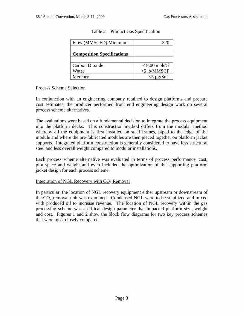
delivered for use in Distributed Control Systems (DCS) with programming supplied by others. UOP process and controls engineers oversee extensive testing once the programming is complete. Alternately, a complete Programmable Logic Controller (PLC) with all programming already installed and tested can be delivered by UOP as a slave unit to the DCS. For this project, the customer selected Honeywell Automation & Control Solutions (in Asia) to program their Honeywell DCS system. As an example, one of the MemGuard system screens used at the Human Machine Interface (HMI) is shown in Figure 5.
Figure 5 – HMI Screen for MemGuard Pretreatment System
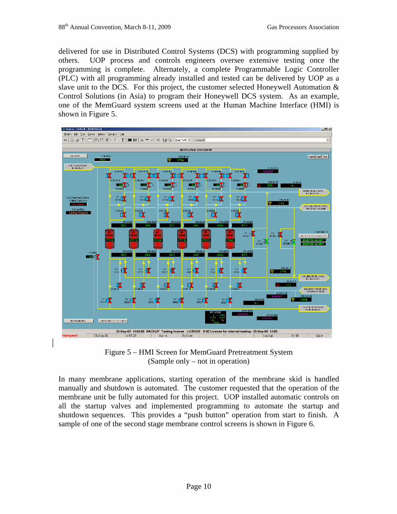
(Sample only – not in operation) In many membrane applications, starting operation of the membrane skid is handled manually and shutdown is automated. The customer requested that the operation of the membrane unit be fully automated for this project. UOP installed automatic controls on all the startup valves and implemented programming to automate the startup and shutdown sequences. This provides a “push button” operation from start to finish. A sample of one of the second stage membrane control screens is shown in Figure 6.
88th Annual Convention, March 8-11, 2009 Gas Processors Association
Page 11
Figure 6 - HMI Screen for Second Stage Membranes (Sample only – not in operation)
System Startup As the first-gas-in startup date approached, the feed stream was expected to contain 30 – 35% CO2 versus the design value of 44.5%. In anticipation of processing this gas, the number of elements loaded in the tubes was reduced to optimize the performance of the unit. Gas first flowed to the platform mid-March of 2007 at very low flow rates. From day one the system met the CO2, water and mercury specifications for the sales gas. Membrane sections (skids) were put in operation such that membrane area matched the amount of gas to be treated. Startups and shutdowns, not related to the UOP system, were frequent during this period. In particular, compression issues caused many shutdowns and re-starts.

88th Annual Convention, March 8-11, 2009 Gas Processors Association
Page 12
The inlet gas rate steadily increased through the next several months as additional wells were tied into the gathering system. During this time, several mechanical issues were corrected. Specific to the UOP supplied equipment, this included:
• Repair of the MemGuard system recycle blower (compressor) impellor which had failed due to debris in the suction piping,
• Vendor repairs of the on-line gas chromatographs, and • Stoppage of hot oil flange leaks at the membrane pre-heaters by replacing flange
rings, repairing flange sealing surfaces and adding new pipe supports. Once the unit operation was stabilized and optimized, a performance test was conducted in October of 2007 over a 26-hour period. Extensive testing was done to confirm the system material balance. Data was obtained from the Honeywell DCS system. Daily averages are shown in the second column of Table 4. The on-line gas chromatographs used for CO2 and hydrocarbon analysis were re-calibrated by the supplier before the test. After identifying one flow meter that was indicating lower than expected rates (despite efforts at re-calibration), minor adjustments of the remaining field data were adequate to close the material balance around the unit.
Table 4 – Performance Test Results
Case
Design Norm
October 2007Test
Extrapolated
Feed Flow, MMSCFD 591 401 581 Feed Pressure, kPag 4000 Min 3736 4000 Feed Temperature, ºC 47 Max 35 35 Feed Composition, Mole % Nitrogen 0.8 1.0 0.9 CO2 44.5 Max 38.7 44.5 H2S, ppm 20 Max <1 20 H2O .2 0.3 0.2 Methane 46.6 53.3 47.6 Ethane 4.2 4.5 4.0 Propane 1.9 1.7 1.6 C4+ 1.5 1.1 1.2 Mercury, µg/Sm3 40 Max n/m 40 Sales Gas Flow, MMSCFD 320 Min 201 320 Membrane Area, % 100 60 100 Sales Composition CO2 8.0 Max 7.6 8.0 H2S, ppm 10 Max 0.05 <10 H2O, lb/MMSCF 5 Max 0.06 <1 Mercury, µg/Sm3 5 Max n/m <5 Hydrocarbon Recovery, % 95.0 Min 95.8 95.7 – 96.0

88th Annual Convention, March 8-11, 2009 Gas Processors Association
Page 13
Because the feed CO2 content and feed gas flow rate were well below design basis values during the performance test, the test data were extrapolated to determine the performance at design values (third column of Table 4). The test data were used to calibrate UOP’s proprietary simulation model and calculate the actual membrane performance properties at the test conditions. The system parameters where then adjusted to increase the feed CO2 to design of 44.5%, bring the sales gas up to 8.0%, and increased feed flow to the rate required to deliver the minimum 320 MMSCFD of sales gas. This final step was modeled with the design amount of primary and secondary membrane area on-line, whereas the test was done with only about 60% of the design area on-line. This extrapolation demonstrated that the unit met system design requirements and will achieve better hydrocarbon recovery by producing 320 MMSCFD of sales gas with less than the 591 MMSCFD feed rate used as the design basis. The performance test results were reviewed with the client, who subsequently accepted unit as having met capacity, product specification and hydrocarbon recovery targets. Recent Operation UOP continues to support the operation of the unit with an on-going contract that includes daily data monitoring. With new wells being added in mid 2008, the feed CO2 increased to near design value of 44.5% and additional feed gas quantities were available for processing. The unit now operates at near design conditions per Table 5.
Table 5 – Recent Unit Performance
Date Oct 10, 2008 Oct 25, 2008 Feed Flow, MMSCFD 533 485 Feed Pressure, kPag 4016 4136 Feed Temperature, ºC 31 32 Membrane inlet Temperature, °C 48 41 Feed Composition, Mole % Nitrogen 1.1 0.7 CO2 43.7 37.2 H2S, ppm <1 H2O Methane 48.9 55.0 Ethane 3.5 4.3 Propane 1.5 1.6 C4+ 1.3 1.2 Mercury, µg/Sm3 n/m n/m Sales Gas Flow, MMSCFD 306 320 Sales Composition CO2 7.7 7.7 H2O, lb/MMSCF On spec On spec Mercury, µg/Sm3 n/m n/m Hydrocarbon Recovery, % 93.2 96.4

88th Annual Convention, March 8-11, 2009 Gas Processors Association
Page 14
As CO2 levels rose, monitoring of individual skid performance indicated that three sections of the primary membranes were performing below expectation. Adjustments were made by increasing the operating temperature at the membranes. While this improves the CO2 removal performance, it also decreases hydrocarbon recovery (see October 10th data). At lower CO2 feed gas levels (October 25th data), the unit can produce the minimum product gas rate with very good hydrocarbon recovery. During a November 2008 shutdown, the three underperforming skids were opened for addition of new elements (to account for the increase in feed CO2 levels versus startup conditions) and for inspection. The first elements in these skids were found to be damaged by water and debris. These elements had been damaged during the initial startup period. In spite of line cleaning, construction debris had not been completely removed. The startup in-line strainers on the feed piping were plugged and were cleaned multiple times during the first several weeks of operation. Closer collaboration with the system fabricator can reduce or eliminate startup damage by more carefully monitoring line installation, cleaning and prevention of moisture accumulation. Despite the early damage to the lead membrane element, the system continued to perform adequately at reduced rates. This is one of the operational benefits of using Separex membrane elements in series in contrast to very large membrane elements installed in parallel. Contaminants do not typically reach downstream elements, so replacing only the first membrane element in each membrane tube is sufficient to restore the performance. The damaged lead elements were replaced and additional elements added during the scheduled shut down. No special lifting equipment was required. Less than 6% of the first stage membrane elements were replaced. The vast majority of the elements in the primary membrane stage will pass two years of service with little reduction in performance. There has been no replacement of second stage elements to date. Conclusion Large offshore gas processing projects are complex and expensive to build. By working closely together, the end user, platform fabricator and technology suppliers can economically complete the projects, meet expected performance goals and realize operational and maintenance benefits. Close collaboration in the early phases of design is essential to arriving at a system design that ensures the lowest installed cost. The UOP MemGuard and Separex process systems, with downstream NGL recovery, meet the specific customer requirements for this project. As of March 2009, the system is operating for two years meeting specifications and without significant membrane replacement.

88th Annual Convention, March 8-11, 2009 Gas Processors Association
Page 15
References 1. Koch, D.R., Buchan, W.R. and Cnop, T., “Proper Pretreatment Systems Reduce
Membrane Replacement Element Cost and Improve Reliability”, 84th Annual Convention Proceedings, Gas Processors Association (2005).
2. Brown, W.G., “Gas Treating Technologies: Which Ones Should be Used and Under What Conditions?”, 87th Annual Convention Proceedings, Gas Processors Association (2008).
3. Markovs, J. and Clark, K., “Optimized Mercury Removal in Gas Plants”, 84th Annual Convention Proceedings, Gas Processors Association (2005).
4. Echt, W.I. and Singh, M., “Integration of Membranes into Natural Gas Process Schemes”, 87th Annual Convention Proceedings, Gas Processors Association (2008).