
Design EZ easy-e Control Valve - Linear Controls...
36
D100401X012 Design EZ easy-e R Control Valve Contents Introduction 1 . . . . . . . . . . . . . . . . . . . . . . . . . . . . . . Scope of Manual 1 . . . . . . . . . . . . . . . . . . . . . . . . . . . . . Description 1 . . . . . . . . . . . . . . . . . . . . . . . . . . . . . . . . . . Specifications 1 . . . . . . . . . . . . . . . . . . . . . . . . . . . . . . . Installation 2 . . . . . . . . . . . . . . . . . . . . . . . . . . . . . . . . Maintenance 3 . . . . . . . . . . . . . . . . . . . . . . . . . . . . . . Packing Lubrication 4 . . . . . . . . . . . . . . . . . . . . . . . . . . Packing Maintenance 5 . . . . . . . . . . . . . . . . . . . . . . . . . Replacing Packing 5 . . . . . . . . . . . . . . . . . . . . . . . . . . Trim Maintenance 9 . . . . . . . . . . . . . . . . . . . . . . . . . . . . Disassembly 9 . . . . . . . . . . . . . . . . . . . . . . . . . . . . . . . Lapping Metal Seats on Valves with Plain and Extension Bonnets 11 . . . . . . . . . . . . . . . . . . Assembly 11 . . . . . . . . . . . . . . . . . . . . . . . . . . . . . . . . ENVIRO-SEAL R Bellows Seal and Bonnet 14 . . . . . Replacing a Plain or Extension Bonnet with an ENVIRO-SEAL Bellows Seal (Stem/Bellows Assembly) and Bonnet 14 . . . . . . . . . . . . . . . . . . Replacing an Installed ENVIRO-SEAL Bellows Seal (Stem/Bellows Assembly) 16 . . . . . . . . . . . Purging the ENVIRO-SEAL Bellows Seal Bonnet 17 . . . . . . . . . . . . . . . . . . . . Parts Ordering 17 . . . . . . . . . . . . . . . . . . . . . . . . . . . Parts Kits 17 . . . . . . . . . . . . . . . . . . . . . . . . . . . . . . . . Parts List 18 . . . . . . . . . . . . . . . . . . . . . . . . . . . . . . . . . Introduction Scope of Manual This instruction manual includes installation, mainte- nance, and parts information for 1/2- through 4-inch Design EZ valve bodies through Class 600 ratings. Refer to separate manuals for instructions covering the actuator and accessories. Only personnel qualified through training or experience should install, operate, and maintain a Design EZ W2137-1/IL Figure 1. Design EZ Valve with Type 667 Actuator and 3582 Series Positioner valve. If you have any questions about these instruc- tions, contact your Fisher Controls sales office or sales representative before proceeding. Description The Design EZ valves (figure 1) are globe-style with integral end connections, post guiding, and quick- change trim. These valves are used in chemical or hydrocarbon processing applications or in applications that require control of nonlubricating, viscous, or other hard-to-handle fluids. Specifications Typical specifications for these valves are shown in table 1. Instruction Manual Form 5118 September 1998 Design EZ
Transcript of Design EZ easy-e Control Valve - Linear Controls...

D10
0401
X01
2
Design EZ easy-e� Control Valve�����
Introduction 1. . . . . . . . . . . . . . . . . . . . . . . . . . . . . . Scope of Manual 1. . . . . . . . . . . . . . . . . . . . . . . . . . . . . Description 1. . . . . . . . . . . . . . . . . . . . . . . . . . . . . . . . . . Specifications 1. . . . . . . . . . . . . . . . . . . . . . . . . . . . . . .
Installation 2. . . . . . . . . . . . . . . . . . . . . . . . . . . . . . . .
Maintenance 3. . . . . . . . . . . . . . . . . . . . . . . . . . . . . . Packing Lubrication 4. . . . . . . . . . . . . . . . . . . . . . . . . . Packing Maintenance 5. . . . . . . . . . . . . . . . . . . . . . . . .
Replacing Packing 5. . . . . . . . . . . . . . . . . . . . . . . . . . Trim Maintenance 9. . . . . . . . . . . . . . . . . . . . . . . . . . . .
Disassembly 9. . . . . . . . . . . . . . . . . . . . . . . . . . . . . . . Lapping Metal Seats on Valves with Plain
and Extension Bonnets 11. . . . . . . . . . . . . . . . . . Assembly 11. . . . . . . . . . . . . . . . . . . . . . . . . . . . . . . .
ENVIRO-SEAL� Bellows Seal and Bonnet 14. . . . . Replacing a Plain or Extension Bonnet with an
ENVIRO-SEAL Bellows Seal (Stem/Bellows Assembly) and Bonnet 14. . . . . . . . . . . . . . . . . .
Replacing an Installed ENVIRO-SEAL BellowsSeal (Stem/Bellows Assembly) 16. . . . . . . . . . .
Purging the ENVIRO-SEALBellows Seal Bonnet 17. . . . . . . . . . . . . . . . . . . .
Parts Ordering 17. . . . . . . . . . . . . . . . . . . . . . . . . . .
Parts Kits 17. . . . . . . . . . . . . . . . . . . . . . . . . . . . . . . .
Parts List 18. . . . . . . . . . . . . . . . . . . . . . . . . . . . . . . . .
����������
Scope of ManualThis instruction manual includes installation, mainte-nance, and parts information for 1/2- through 4-inchDesign EZ valve bodies through Class 600 ratings.Refer to separate manuals for instructions coveringthe actuator and accessories.
Only personnel qualified through training or experienceshould install, operate, and maintain a Design EZ
W2137-1/IL
Figure 1. Design EZ Valve with Type 667Actuator and 3582 Series Positioner
valve. If you have any questions about these instruc-tions, contact your Fisher Controls sales office orsales representative before proceeding.
DescriptionThe Design EZ valves (figure 1) are globe-style withintegral end connections, post guiding, and quick-change trim. These valves are used in chemical orhydrocarbon processing applications or in applicationsthat require control of nonlubricating, viscous, or otherhard-to-handle fluids.
SpecificationsTypical specifications for these valves are shown intable 1.
Instruction ManualForm 5118September 1998 Design EZ
Design EZ
2
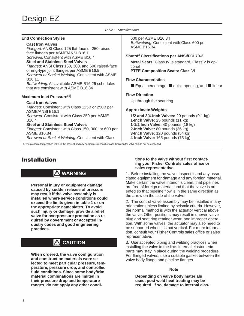
Table 1. Specifications
End Connection Styles
Cast Iron ValvesFlanged: ANSI Class 125 flat-face or 250 raised-face flanges per ASME/ANSI B16.1Screwed: Consistent with ASME B16.4Steel and Stainless Steel ValvesFlanged: ANSI Class 150, 300, and 600 raised-faceor ring-type joint flanges per ASME B16.5Screwed or Socket Welding: Consistent with ASMEB16.11Buttwelding: All available ASME B16.25 schedulesthat are consistent with ASME B16.34
Maximum Inlet Pressure (1)
Cast Iron ValvesFlanged: Consistent with Class 125B or 250B perASME/ANSI B16.1Screwed: Consistent with Class 250 per ASMEB16.4Steel and Stainless Steel ValvesFlanged: Consistent with Class 150, 300, or 600 perASME B16.34Screwed or Socket Welding: Consistent with Class
600 per ASME B16.34Buttwelding: Consistent with Class 600 perASME B16.34
Shutoff Classifications per ANSI/FCI 70-2
Metal Seats: Class IV is standard, Class V is op-tionalPTFE Composition Seats: Class VI
Flow Characteristics
� Equal percentage, � quick opening, and � linear
Flow Direction
Up through the seat ring
Approximate Weights
1/2 and 3/4-Inch Valves: 20 pounds (9.1 kg)1-Inch Valve: 25 pounds (11 kg)1-1/2 Inch Valve: 40 pounds (18 kg)2-Inch Valve: 80 pounds (36 kg)3-Inch Valve: 120 pounds (54 kg)4-Inch Valve: 165 pounds (75 kg)
1. The pressure/temperature limits in this manual and any applicable standard or code limitation for valve should not be exceeded.
������������
WARNING
Personal injury or equipment damagecaused by sudden release of pressuremay result if the valve assembly isinstalled where service conditions couldexceed the limits given in table 1 or onthe appropriate nameplates. To avoidsuch injury or damage, provide a reliefvalve for overpressure protection as re-quired by government or accepted in-dustry codes and good engineeringpractices.
CAUTION
When ordered, the valve configurationand construction materials were se-lected to meet particular pressure, tem-perature, pressure drop, and controlledfluid conditions. Since some body/trimmaterial combinations are limited intheir pressure drop and temperatureranges, do not apply any other condi-
tions to the valve without first contact-ing your Fisher Controls sales office orsales representative.
1. Before installing the valve, inspect it and any asso-ciated equipment for damage and any foreign material.Make certain the valve interior is clean, that pipelinesare free of foreign material, and that the valve is ori-ented so that pipeline flow is in the same direction asthe arrow on the side of the valve.
2. The control valve assembly may be installed in anyorientation unless limited by seismic criteria. However,the normal method is with the actuator vertical abovethe valve. Other positions may result in uneven valveplug and seat ring retainer wear, and improper opera-tion. With some valves, the actuator may also need tobe supported when it is not vertical. For more informa-tion, consult your Fisher Controls sales office or salesrepresentative.
3. Use accepted piping and welding practices wheninstalling the valve in the line. Internal elastomericparts may stay in place during the welding procedure.For flanged valves, use a suitable gasket between thevalve body flange and pipeline flanges.
Note
Depending on valve body materialsused, post weld heat treating may berequired. If so, damage to internal elas-

Design EZ
3
tomeric and plastic parts, as well as in-ternal metal parts is possible. Shrunk-fitpieces and threaded connections mayalso loosen. In general, if post weld heattreating is to be performed, all trim partsshould be removed. Contact your FisherControls sales office or representativefor additional information.
4. With a leak-off bonnet construction, remove thepipe plugs (key 14, figure 11) to hook up the leak-offpiping. If continuous operation is required during in-spection or maintenance, install a three-valve bypassaround the control valve assembly.
5. If the actuator and valve are shipped separately,refer to the actuator mounting procedure in the ap-propriate actuator instruction manual.
WARNING
Personal injury could result from pack-ing leakage. Valve packing was tight-ened before shipment; however, thepacking might require some readjust-ment to meet specific service condi-tions.
Valves with ENVIRO-SEAL live-loaded packing orHIGH-SEAL� Heavy-Duty live-loaded packing will notrequire this initial re-adjustment. See the FisherControls instruction manuals titled ENVIRO-SEALPacking System for Sliding-Stem Valves or Heavy-Duty Live-Loaded Packing System (as appropriate) forpacking instructions. If you wish to convert your pres-ent packing arrangement to ENVIRO-SEAL packing,refer to the retrofit kits listed in the Parts Kits sub-sec-tion near the end of this manual.
�����������
Valve parts are subject to normal wear and must beinspected and replaced as necessary. Inspection andmaintenance frequency depends on the severity ofservice conditions. This section includes instructionsfor packing lubrication, packing maintenance, trimmaintenance, and ENVIRO-SEAL bellows seal re-placement. All maintenance operations may be per-formed with the valve in the line.
WARNING
Avoid personal injury or property dam-age from sudden release of processpressure or bursting of parts. Before
Figure 2. Optional Packing Lubricator andLubricator/Isolating Valve
������� �
������� ������ ��������
10A9421-AAJ5428-DA0832-2/IL
performing any maintenance opera-tions:
� Disconnect any operating lines pro-viding air pressure, electric power, or acontrol signal to the actuator. Be surethe actuator cannot suddenly open orclose the valve.
� Use bypass valves or completelyshut off the process to isolate the valvefrom process pressure. Relieve processpressure from both sides of the valve.Drain the process media from bothsides of the valve.
� Vent the pneumatic actuator load-ing pressure and relieve any actuatorspring precompression.
� Use lock-out procedures to be surethat the above measures stay in effectwhile you work on the equipment.
Note
Whenever a gasket seal is disturbed byremoving or shifting gasketed parts, anew gasket should be installed uponreassembly. This is necessary to ensurea good gasket seal since the used gas-ket may not seal properly.

Design EZ
4
Figure 3. PTFE V-Ring Packing Arrangements for Plain and Extension Bonnets
12A37837-AB1429-5*/IL
B1428-5*
Because of the care Fisher Controls takes in meetingall manufacturing requirements (heat treating, dimen-sional tolerances, etc.), use only replacement partsmanufactured or furnished by Fisher Controls.
Note
If the valve has ENVIRO-SEAL orHIGH-SEAL live-loaded packing installed,refer to instruction manualsENVIRO-SEAL Packing System for Slid-ing Stem Valves , Form 5306, orHIGH-SEAL Live Loaded Packing System ,Form 5263, for packing instructions. Fig-ure 6 shows a typical HIGH-SEAL packingsystem. Figures 7 and 8 show typical ENVIRO-SEAL systems.
Packing LubricationNote
ENVIRO-SEAL or HIGH-SEAL packingdoes not require lubrication.
If an optional lubricator or lubricator/isolating valve (fig-ure 2) is provided for PTFE/composition or other pack-ings that require lubrication, it will be installed an op-tional tapped hole in the bonnet. Use a good qualitysilicon-base lubricant. Packing used in oxygen serviceor in processes with temperatures over 500�F (260�C)should not be lubricated. To operate the lubricator,simply turn the cap screw clockwise to force the lubri-cant into the packing box. The lubricator/isolatingvalve must first be opened and then closed after lu-brication is completed.

Design EZ
5
Figure 4. PTFE/Composition Packing Arrangements forPlain and Extension Bonnets
B0968-1*/IL
12A8188-A 12A7815-A 12A8173-A
Packing MaintenanceThis section covers PTFE V-ring, PTFE/composition,and graphite/ribbon packing as used in plain and ex-tension bonnets. Unless otherwise indicated, key num-bers refer to figure 3 for PTFE V-ring packing, figure 4for PTFE/composition packing, and figure 5 for graph-ite ribbon/filament packing.
For spring-loaded single PTFE V-ring packing, thespring (key 8, figure 3) maintains a sealing force onthe packing. If leakage is noted around the packingfollower (key 13, figure 3), check to be sure the shoul-der on the packing follower is touching the bonnet. Ifthe shoulder is not touching the bonnet, tighten thepacking flange nuts (key 5, figure 11), until the shoul-der is against the bonnet. If leakage cannot bestopped in this manner, proceed to the ReplacingPacking procedure.
If there is unacceptable packing leakage with otherthan spring-loaded packing, first try to limit the leakageand establish a stem seal by tightening the packingflange nuts.
If the packing is relatively new and tight on the stem,and if tightening the packing flange nuts does not stopthe leakage, the valve stem may be worn or nicked sothat a seal cannot be made. The surface finish of avalve stem is critical for making a good packing seal. Ifthe leakage comes from the outside diameter of thepacking, the leakage may be caused by nicks or
scratches around the packing box wall. If performingany of the following procedures, inspect the valvestem and packing box wall for nicks and scratches.
An illustration of a HIGH-SEAL live-loaded packingsystem is shown in figure 6. Illustrations ofENVIRO-SEAL live-loaded packing systems areshown in figures 7, 8, and 9.
Replacing PackingThis section covers replacing packing used in plainand extension bonnets. PTFE V-ring packing is shownin figure 3, PTFE/composition packing is shown in fig-ure 4, and graphite/ribbon packing is shown in figure 5.
1. Isolate the control valve from the line pressure, re-lease pressure from both sides of the valve body, anddrain the process media from both sides of the valve.If using a power actuator, also shut off all pressurelines to the power actuator, and release all pressurefrom the actuator. Use lock-out procedures to be surethat the above measures stay in effect while you workon the equipment. Observe the warning at the start ofthe Maintenance section.
2. Disconnect the operating lines from the actuatorand any leak-off piping from the bonnet. Disconnectthe stem connector and then remove the actuator fromthe valve by unscrewing the yoke locknut (key 15, fig-ure 11).

Design EZ
6
Figure 5. Graphite Ribbon/Filament Packing Arrangementsfor Plain and Extension Bonnets
NOTE: 0.004 INCH (0.102 mm) THICK SACRIFICIAL ZINC WASHERS:USE ONLY ONE BELOW EACH GRAPHITE RIBBON RING.1
A5514-2/IL
A5513-2/IL
WARNING
To avoid personal injury or propertydamage caused by uncontrolled move-ment of the bonnet, loosen the bonnetby following the instructions in the nextstep. Do not remove a stuck bonnet bypulling on it with equipment that canstretch or store energy in any othermanner. The sudden release of storedenergy can cause uncontrolled move-ment of the bonnet. If the seat ring re-tainer sticks to the bonnet, proceedcarefully with bonnet removal.
Note
The following step also provides addi-tional assurance that the valve bodyfluid pressure has been relieved.
3. Hex nuts (key 16, figure 11) attach the bonnet tothe valve. Loosen these nuts or cap screws approxi-mately 1/8 inch (3 mm). Then loosen the body-to-bon-net gasketed joint by either rocking the bonnet or pry-ing between the bonnet and valve body. Work theprying tool around the bonnet until the bonnet loosens.
4. Loosen the packing flange nuts (key 5, figure 11)so that the packing is not tight on the valve stem. Re-move any travel indicator parts and stem locknutsfrom the valve stem threads.
CAUTION
Avoid damaging the seating surfacecaused by the valve plug and stem as-sembly dropping from the bonnet afterbeing lifted part way out. When liftingthe bonnet, temporarily install a valvestem locknut on the valve stem. Thislocknut will prevent the valve plug andstem assembly from dropping out of thebonnet.
Design EZ
7
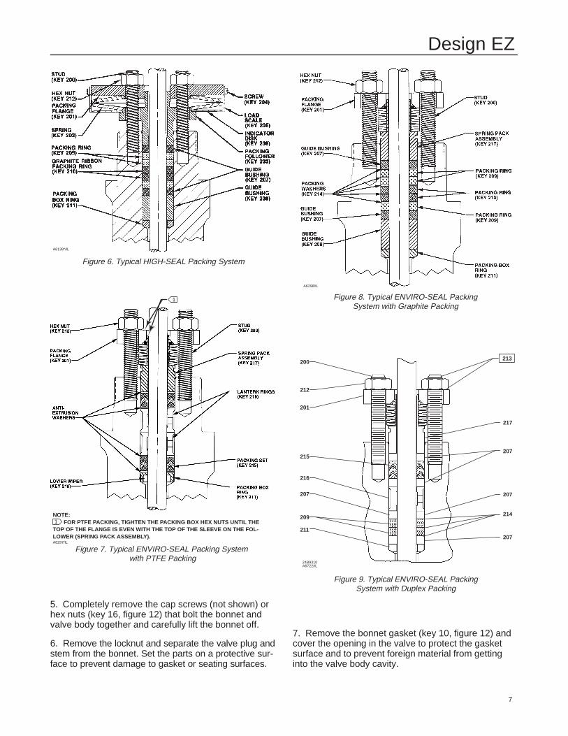
Figure 6. Typical HIGH-SEAL Packing System
A6138*/IL
Figure 7. Typical ENVIRO-SEAL Packing System with PTFE Packing
NOTE: FOR PTFE PACKING, TIGHTEN THE PACKING BOX HEX NUTS UNTIL THETOP OF THE FLANGE IS EVEN WITH THE TOP OF THE SLEEVE ON THE FOL-LOWER (SPRING PACK ASSEMBLY).
1
1
A6297/IL
5. Completely remove the cap screws (not shown) orhex nuts (key 16, figure 12) that bolt the bonnet andvalve body together and carefully lift the bonnet off.
6. Remove the locknut and separate the valve plug andstem from the bonnet. Set the parts on a protective sur-face to prevent damage to gasket or seating surfaces.
Figure 8. Typical ENVIRO-SEAL PackingSystem with Graphite Packing
A6298/IL
Figure 9. Typical ENVIRO-SEAL PackingSystem with Duplex Packing
200
212
201
215
216
207
209
211
217
207
207
207
214
213
24B9310A6722/IL
7. Remove the bonnet gasket (key 10, figure 12) andcover the opening in the valve to protect the gasketsurface and to prevent foreign material from gettinginto the valve body cavity.

Design EZ
8
Table 2. Body-to-Bonnet Torque GuidelinesVALVE SIZE, INCHES TORQUES(1)
Design EZ
Field-LubricatedBolting
Stud Bolt NutsFactory Prelubricated
w/Molykote321R Dry Film Lubricant
Design EZBolt Material Bolt Material
SA193-B7 SA193-B8M (2) SA193-B7 SA193-B8M (2)
Lbf �ft N�m Lbf �ft N�m Lbf �ft N�m Lbf �ft N�m
1 or smaller 95 129 47 64 75 102 37 50
1-1/2 or 2 71 96 33 45 56 76 26 35
3 125 169 65 88 97 132 51 69
4 200 271 115 156 155 210 89 1211. Determined from laboratory tests.2. SA193-B8M annealed.
8. Remove the packing flange nuts, packing flange,upper wiper, and packing follower (keys 5, 3, 12, and13, figure 11). Carefully push out all the remainingpacking parts from the valve side of the bonnet usinga rounded rod or other tool that will not scratch thepacking box wall. Clean the packing box and the metalpacking parts.
9. Inspect the valve stem threads and the packing boxsurfaces for any sharp edges which might cut thepacking. Scratches or burrs could cause packing boxleakage or damage to the new packing. If the surfacecondition cannot be improved by light sanding, replacethe damaged parts.
10. Remove the covering protecting the valve cavityand install a new bonnet gasket (key 10, figure 12),making sure the gasket seating surfaces are clean andsmooth. Then slide the bonnet over the stem and ontothe stud bolts (key 15, figure 12), or onto the valvecavity if cap screws (not shown) are used instead.
Note
Proper performance of the tighteningprocedures in step 11 compresses thespiral wound gasket (key 12, figure 12)enough to both load and seal the seatring gasket (key 13, figure 12). The tight-ening procedures also compresses theouter edge of the bonnet gasket (key 10,figure 12) enough to seal the body-to-bonnet joint.
The prelubricated stud bolt nuts (key 16,figure 12) referred to in step 11 are iden-tified by a black film coating on the nutthreads.
The accepted bolting procedures re-ferred to in step 11 include—but are notlimited to—ensuring that boltingthreads are clean, and evenly tighteningthe cap screws, or the nuts onto thestuds, in a crisscross pattern. Because
of the boltup characteristics of spiralwound gaskets, tightening one capscrew or nut may loosen an adjacentcap screw or nut. Repeat the crisscrosstightening pattern several times untileach cap screw or nut is tight and thebody-to-bonnet seal is made. When theoperating temperature has beenreached, perform this torquing proce-dure once again.
11. Install bolting, using accepted bolting proceduresduring tightening so that the body-to-bonnet joint canwithstand test pressures and application service condi-tions. The bolt torques in table 2 may be used asguidelines unless accepted bolting procedures dictateotherwise.
12. Install new packing and the metal packing boxparts according to the appropriate arrangement in fig-ure 3, 4, or 5. If split-ring packing is being added, alter-nate the position of the splits to avoid a leak path.Place a smooth-edged pipe over the valve stem andgently tap each soft packing part into the packing box,being sure that air is not trapped between adjacentsoft parts.
Installation of graphite ribbon packing requires specialcare to avoid trapping air between the rings. Start withonly one ring at a time without forcing the top of thepacking ring below the bottom of the entrance chamferof the packing box. Thus, when a ring is added, thestack should not be pushed into the cavity more thanthe thickness of the added ring.
13. Slide the packing follower, upper wiper, and pack-ing flange (keys 13, 12, and 3, figure 11) into position.Lubricate the packing flange studs (key 4, figure 11)and the faces of the packing flange nuts (key 5, figure11). Install the packing flange nuts.
Note
The torque values discussed in step 14and shown in table 3 are recommended

Design EZ
9
guidelines only and are presented as astarting point for this procedure. Tight-ening the packing flange nuts to atorque value that exceeds the tableguidelines, in order to obtain a seal,may indicate other problems.
14. For spring-loaded PTFE V-ring packing, tightenthe packing flange nuts until the shoulder on the packingfollower (key 13, figure 11) contacts the bonnet.
For graphite packing, tighten the packing flange nuts tothe maximum recommended torque shown in table 3.Then, loosen the packing flange nuts, and retighten themto the recommended minimum torque shown in table 3.
For other packing types, tighten the packing flangenuts alternately in small equal increments until one ofthe nuts reaches the minimum recommended torqueshown in table 3. Then, tighten the remaining flangenuts until the packing flange is level and at a 90-de-gree angle to the valve stem.
For ENVIRO-SEAL or HIGH-SEAL live-loadedpacking, refer to the note at the beginning of theMaintenance section on page 4 of this manual.
15. Mount the actuator on the valve body and recon-nect the actuator and valve stem according to the pro-cedure in the appropriate actuator instruction manual.
Trim MaintenanceThis procedure describes how the valve trim can becompletely disassembled. When inspection or repairsare required, perform only those steps necessary toaccomplish the task. Observe the warning at the startof the Maintenance section.
DisassemblyExcept where indicated, key numbers referenced inthe following steps are found in figure 12.
1. Remove the actuator and the bonnet according tosteps 1 through 6 of the Replacing Packing procedureof the Maintenance section.
CAUTION
To avoid personal injury due to leakingfluids, avoid damaging gasket sealingsurfaces.
The surface finish of the valve stem (key7) is critical for making a good packingseal. The inside surface of the seat ringretainer is critical for smooth operationof the valve plug.
Table 3. Recommended Torque for Packing Flange Nuts(Not for Spring-Loaded Packing)
VALVESTEM ANSI
GRAPHITE TYPEPACKING
PTFE TYPEPACKING
STEMDIAMETER
ANSICLASS
MinimumTorque
MaximumTorque
MinimumTorque
MaximumTorque
Inches mm Lbf �in N�m Lbf �in N�m Lbf �in N�m Lbf �in N�m
125,150
27 3 40 5 13 1 19 2
3/8 9.5 250300
36 4 53 6 17 2 26 3
600 49 6 73 8 23 3 35 4
125,150
44 5 66 8 21 2 31 4
1/2 12.7 250300
59 7 88 10 28 3 42 5
600 81 9 122 14 39 4 58 7
125,150
99 11 149 17 47 5 70 8
3/4 19.1 250300
133 15 199 23 64 7 95 11
600 182 21 274 31 87 10 131 15
The seating surfaces of the valve plugand seat ring (keys 2 and 9) are criticalfor proper shutoff.
Unless inspection reveals otherwise, as-sume all these parts are in good condi-tion and protect them accordingly. Gas-ket selection criteria is provided onpage 33 of this instruction manual.
2. Packing parts can be removed if desired. Replacethese parts as described in the Replacing Packing pro-cedure.
Valves with Plain or Extension Bonnets
Perform the following steps to remove the valve trim.
1. Lift the valve plug and stem assembly [or the plugguide, disk retainer, and disk (keys 27, 28, and 29,figure 13) if used], out of the valve body and set it on aprotective surface.
Note
With some valve plug sizes and configu-rations, the seat ring retainer and bushingassembly (keys 3 and 26, figures 12 and13) will come out of the valve body withthe valve plug and stem assembly, and inother valve plug sizes and configurations,the valve plug or tip will slide through theseat ring retainer and bushing assembly,leaving the retainer and bushing assem-bly in the valve body.
2. With the valve plug and stem assembly out of thevalve, either slide the seat ring retainer and bushingassembly (keys 3 and 26), and gaskets and shim(keys 10, 12, and 25) up over the valve plug and stem
Design EZ
10
or lift the seat ring retainer and bushing assembly andassociated gaskets and shim out of the valve body. Ifthe valve plug is to be reused, protect the valve plugseating surface to prevent scratches.
3. For valves with metal seats, drive out the pin(key 8) and unscrew the valve stem (key 7) from thevalve plug (key 2).
4. For valves with 1/4 and 3/8-inch ports and com-position seats, refer to figure 13. Drive out the pin(key 8) and unscrew the valve stem (key 7) from thevalve plug guide (key 27). Unscrew the disk retainer(key 28) from the valve plug guide. Remove the disk(key 29) from the valve plug tip (key 30).
For valves with 1/2 through 2-inch ports and com-position seats, refer to figure 13. Drive out the pin(key 8) and unscrew the valve stem (key 7) from thevalve plug guide (key 27). Drive out pin (key 31) andunscrew the tip (key 30) from the valve plug guide.Remove the disk (key 29) from the valve plug guide.
For valves with 3 and 4-inch ports and composi-tion seats, refer to figure 13. Drive out the pin (key 8)and unscrew the valve stem from the valve plug guide(key 27).Remove the cap screw (key 32) to removethe tip (key 30) from the valve plug guide. Remove thedisk (key 29).
5. Remove the seat ring and seat ring gasket (keys 9and 13).
6. Inspect parts for wear or damage that would pre-vent proper operation of the valve. Replace or repairtrim parts according to the following Lapping MetalSeats or Assembly procedure as appropriate.
Valves with ENVIRO-SEAL Bellows Seal Bonnets
Perform the following steps to remove the valve trim.
1. Lift the stem/bellows assembly with valve plug at-tached [or the plug guide, disk retainer, and disk (keys27, 28, and 29, figure 13) if used], seat ring retainerand gaskets out of the valve body and set them on aprotective surface.
Note
With some valve plug sizes and configu-rations, the seat ring retainer and bush-ing assembly (keys 3 and 26, figures 12and 13) will come out of the valve bodywith the stem/bellows, and in othervalve plug sizes and configurations, thevalve plug or tip will slide through theseat ring retainer and bushing assem-bly, leaving the retainer and bushing as-sembly in the valve body.
2. If the seat ring retainer and bushing assembly(keys 3 and 26) stayed in the valve, lift them out alongwith gaskets and shim (keys 10, 12, and 25).
3. If the seat ring retainer and bushing assembly(keys 3 and 26) came out of the valve with the stem/bellows assembly, move the seat ring retainer andbushing assembly against the shoulder of the valveplug (key 2) or valve plug guide (key 27, figure 13) toprovide access to the pin (key 36, figure 11).
4. Place the stem/bellows assembly and valve plug orvalve plug guide in a soft-jaw chuck or other type ofvise so that the jaws grip a portion of the valve plug orvalve plug guide that is not a seating or guiding sur-face. Drive out the pin (key 36, figure 11).
5. Remove the stem/bellows assembly from the soft-jaw chuck or vise. Place a wrench on the flat areas onthe valve stem just below the threads for the actuator/stem connection to keep the stem from turning. Then,unscrew the adaptor (key 24, figure 11), which alsoincludes the valve plug (key 2) or valve plug guide(key 27, figure 13), from the stem/bellows assembly(key 20, figure 11).
6. Remove the seat ring retainer and bushing assem-bly (keys 3 and 26) by sliding it over the adaptor. If thevalve plug is to be reused, protect the valve plug seat-ing surface to prevent scratches.
7. For valves with metal seats, drive out the pin(key 8) and unscrew the adaptor (key 24, figure 11)from the valve plug (key 2).
8. For valves with 1/4 and 3/8-inch ports and com-position seats, refer to figure 13. Drive out the pin(key 8) and unscrew the adaptor (key 24, figure 11)from the valve plug guide (key 27). Unscrew the diskretainer (key 28) from the valve plug guide. Removethe disk (key 29) from the valve plug tip (key 30).
For valves with 1/2 through 2-inch ports and com-position seats, refer to figure 13. Drive out the pin(key 8) and unscrew the adaptor (key 24, figure 11)from the valve plug guide (key 27). Drive out pin (key31) and unscrew the tip (key 30) from the valve plugguide. Remove the disk (key 29) from the valve plugguide.
For valves with 3 and 4-inch ports and composi-tion seats, refer to figure 13. Drive out the pin (key8) and unscrew the adaptor (key 24, figure 11) fromthe valve plug guide (key 27).Remove the cap screw(key 32) to remove the tip (key 30) from the valve plugguide. Remove the disk (key 29).
9. Remove the seat ring and seat ring gasket (keys 9and 13).
10. Inspect parts for wear or damage that would pre-vent proper operation of the valve. Replace or repairtrim parts according to the following Assembly proce-dure as appropriate.

Design EZ
11
Lapping Metal Seats on Valves with Plainand Extension Bonnets
CAUTION
To avoid damaging the ENVIRO-SEALBellows Seal Bonnet assembly, do notattempt to lap the metal seating sur-faces on valves with ENVIRO-SEAL bel-lows seal bonnets. The design of thebonnet assembly prevents rotation ofthe stem and any forced lapping rota-tion will damage internal components ofthe ENVIRO-SEAL Bellows Seal bonnet.
With metal-seat constructions, seating surfaces of thevalve plug and seat ring (key 2, figure 12) can belapped for improved shutoff. (Deep nicks should bemachined out rather than ground out.) Use a goodquality lapping compound of a mixture of 280 to600-grit. Apply the compound to the bottom of thevalve plug.
Assemble the valve to the extent that the seat ringretainer is in place and the bonnet is bolted to thevalve body. A simple handle can be made from apiece of strap iron locked to the valve plug stem withnuts. Rotate the handle alternately in each direction tolap the seats. After lapping, remove the bonnet andclean the seat surfaces. Completely assemble as de-scribed in the assembly portion of the Trim Mainte-nance procedure and test the valve for shutoff. Repeatthe lapping procedure if leakage is still excessive.
AssemblyThis procedure assumes that all the trim and associat-ed gaskets were removed from the valve body. Ifthese parts were not all removed, start the assemblyprocedure at the appropriate step. Except where indi-cated, key numbers referenced in the following stepsare found in figure 12.
Valves with Plain or Extension Bonnets
Perform the following steps to assemble and install thetrim.
CAUTION
To avoid weakening the stem that maycause failure in service, never reuse anold stem with a new valve plug. Usingan old stem with a new plug requiresdrilling a new pin hole in the stem,whichwill weaken the stem. However, a usedvalve plug may be reused with a newstem.
VALVE STEM BOLT TORQUE DRILL SIZE, D DIMENSION
Inch mm Lbf �ft N�mDRILL SIZE,
INCH Inch mm
3/81/23/4
9.512.719.0
25-3560-85
175-250
40-4781-115237-339
3/321/83/16
5/83/41
161925
Figure 10. Bolt Torque for Plug/Stem Connection andPlug/Adaptor Connection and Pin Replacement
CU8376–C35A5717–CA2415–2/IL
1. For valves with metal seats, screw the valvestem (key 7) into the valve plug (key 2). Tighten to thetorque valve given in figure 10. Refer to figure 10 toselect the proper drill size. Drill through the stem usingthe hole in the valve plug as a guide. Remove anychips or burrs and drive in a new pin (key 8) to lockthe assembly.
2. For valves with 1/4 and 3/8-inch ports and com-position seats, refer to figure 13. Place the disk(key 29) on the valve plug tip (key 30). Place the diskretainer (key 28) over the disk, and then thread thedisk retainer onto the valve plug guide (key 27).
CAUTION
To avoid failure in service for valveswith 1/2 through 1-inch ports and com-position seats, never reuse an old valveplug guide with a new valve plug tip.Using an old valve plug guide with anew plug tip requires drilling a new pinhole in the valve plug guide, which willweaken the guide. However, a usedvalve plug tip may be reused with a newvalve plug guide.
For valves with 1/2 through 1-inch ports and com-position seats, refer to figure 13. Insert the disk (key29) in the valve plug guide (key 27). Screw the tip (key30) onto the valve plug guide to clamp the disk in place.Using a 3/32-inch bit, drill through the valve plug guideusing the hole in the tip as a drilling guide. Remove anychips or burrs and drive in a new pin (key 31).

Design EZ
12
CAUTION
To avoid failure in service for valveswith 1-1/2 and 2-inch ports and com-position seats, never reuse an old valveplug tip with a new valve plug guide.Using an old valve plug tip with a newvalve plug guide requires drilling a newpin hole in the valve plug tip which willweaken the tip. However, a used valveplug guide may be reused with a newvalve plug tip.
For valves with 1-1/2 and 2-inch ports and com-position seats, refer to figure 13. Insert the disk(key 29) in the valve plug guide (key 27). Screw the tip(key 30) into the valve plug guide to clamp the disk inplace. Using a 3/32-inch bit, drill through the valveplug tip using the hole in the valve plug guide as a dril-ling guide. Remove any chips or burrs and drive in anew pin (key 31).
For valves with 3 and 4-inch ports and composi-tion seats, refer to figure 13. Insert the disk (key 29)in the valve plug guide (key 27). Place the tip (key 30)against the valve plug guide to clamp the disk in place.Insert the cap screw (key 32) through the tip andthread it into valve plug guide to secure the tip to thevalve plug guide.
CAUTION
To avoid failure in service, never reusean old stem with a new valve plugguide. Using an old stem with a newvalve plug guide requires drilling a newpin hole in the stem, which will weakenthe stem. However, a used valve plugguide may be reused with a new stemexcept for valves with 1/2 through1-inch ports and composition seats (seeto figure 13). For these constructions, aused valve plug guide should only beused if the tip is reused.
3. For all valves with composition seats, screw thevalve stem (key 7) into the valve plug guide (key 27,figure 13). Tighten to the torque value given in figure10. Refer to figure 10 to select the proper drill size.Drill through the stem, using the hole in the valve plugguide as a drilling guide. Remove any chips or burrsand drive in a new pin (key 8) to lock the assembly.
4. Install the seat ring gasket (key 13), and replacethe seat ring (key 9).
Note
With some valve plug sizes and configu-rations, the valve plug or tip will slidethrough the seat ring retainer and bush-ing assembly (keys 3 and 26), and inother configurations it won’t.
5. If the valve plug (key 2) or valve plug tip (key 30,figure 13) will not slide through the seat ring retainerand bushing assembly (keys 3 and 26), proceed asfollows:
a. Place the seat ring retainer and bushing assem-bly (keys 3 and 26) over the stem of valve plug andstem assembly or over the stem of the valve plugguide and stem assembly.
b. Install the seat ring retainer and bushing assem-bly, which also includes the valve plug and stemassembly or valve plug guide and stem assembly,on the top of the seat ring, ensuring that the seatring retainer slips onto the seat ring properly. Anyrotation orientation of the seat ring retainer withrespect to the valve body is acceptable.
c. Place the spiral wound gasket, shim, and bon-net gasket (keys 12, 25, and 10) on the shoulder ofthe seat ring retainer.
6. If the valve plug (key 2) or the valve plug tip (key30, figure 13) will slide through the seat ring retainerand bushing assembly (keys 3 and 26), proceed asfollows:
a. Install the seat ring retainer and bushing assem-bly on the top of the seat ring, ensuring that theseat ring retainer slips onto the seat ring properly.Any rotation orientation of the seat ring retainerwith respect to the valve body is acceptable.
b. Place the spiral wound gasket, shim, and bon-net gasket (keys 12, 25, and 10) on the shoulder ofthe seat ring retainer.
c. Slide the valve plug and stem assembly or thevalve plug guide and stem assembly into the seatring retainer and bushing assembly (keys 3 and26).
7. Mount the bonnet on the valve body and completethe assembly according to steps 10 through 15 of theReplacing Packing procedure, omitting steps 12 and13 if new packing is not being installed, and being sureto observe the note prior to step 11.
Valves with ENVIRO-SEAL Bellows Seal Bonnets
Perform the following steps to assemble and install thetrim.
1. For valves with 1/4 and 3/8-inch ports and com-position seats, refer to figure 13. Place the disk

Design EZ
13
(key 29) on the valve plug tip (key 30). Place the diskretainer (key 28) over the disk, and then thread thedisk retainer onto the valve plug guide (key 27).
CAUTION
To avoid failure in service of valves with1/2 through 1-inch ports and composi-tion seats, never reuse an old valve plugguide with a new valve plug tip. Usingan old valve plug guide with a new plugtip requires drilling a new pin hole in thevalve plug guide, which will weaken theguide. However, a used valve plug tipmay be reused with a new valve plugguide.
For valves with 1/2 through 1-inch ports and com-position seats, refer to figure 13. Insert the disk (key29) in the valve plug guide (key 27). Screw the tip (key30) onto the valve plug guide to clamp the disk in place.Using a 3/32-inch bit, drill through the valve plug guideusing the hole in the tip as a drilling guide. Remove anychips or burrs and drive in a new pin (key 31).
CAUTION
To avoid failure in service of valves with1-1/2 and 2-inch ports and compositionseats, never reuse an old valve plug tipwith a new valve plug guide. Using anold valve plug tip with a new valve plugguide requires drilling a new pin hole inthe valve plug tip, which will weaken thetip. However, a used valve plug guidemay be reused with a new valve plug tip.
For valves with 1-1/2 and 2-inch ports and composi-tion seats, refer to figure 13. Insert the disk (key 29) inthe valve plug guide (key 27). Screw the tip (key 30) intothe valve plug guide to clamp the disk in place. Using a3/32-inch bit, drill through the valve plug tip using thehole in the valve plug guide as a drilling guide. Removeany chips or burrs and drive in a new pin (key 31).
For valves with 3 and 4-inch ports and composi-tion seats, refer to figure 13. Insert the disk (key 29)in the valve plug guide (key 27). Place the tip (key 30)against the valve plug guide to clamp the disk in place.Insert the cap screw (key 32) through the tip andthread it into valve plug guide to secure the tip to thevalve plug guide.
CAUTION
To avoid weakening the adaptor thatmay cause failure in service, never re-use an old adaptor with a new valveplug or valve plug guide. Using an oldadaptor with a new valve plug or valveplug guide requires drilling a new pinhole in the adaptor, which will weakenthe adaptor. However, a used valve plugor valve plug guide may be reused witha new adaptor.
2. Thread the valve plug (key 2) or, the valve plugguide (key 27, figure 13) if the valve has compositionseats, onto the adaptor (key 24, figure 11). Tighten tothe torque valve given in figure 10. Refer to figure 10to select the proper drill size. Drill through the adaptorusing the hole in the valve plug as a guide. Removeany chips or burrs and drive in a new pin (key 8) tolock the assembly.
Note
With some valve plug sizes and configu-rations, the valve plug or tip will slidethrough the seat ring retainer and bush-ing assembly, and in other configura-tions it won’t.
3. If the valve plug (key 2) or valve plug tip (key 30,figure 13) will not slide through the seat ring retainerand bushing assembly (keys 3 and 26), proceed asfollows:
a. Slide the seat ring retainer and bushing assem-bly (keys 3 and 26) over the adaptor (key 24, figure11) so that the bushing rests on the shoulder of thevalve plug or valve plug guide.
b. Place the spiral wound gasket, shim, and bon-net gasket (keys 12, 25, and 10) on the shoulder ofthe seat ring retainer.
c. Place a wrench on the flat areas of the stem justbelow the threads for the actuator/stem connectionto keep the stem from turning.
d. Screw the adaptor (key 24, figure 11), whichalso includes the valve plug or valve plug guide andseat ring retainer and bushing assembly and gas-kets, onto the stem/bellows assembly (key 20, fig-ure 11). Tighten the adaptor until it is snug. Then,turn the adaptor until the valve stem hole lines upwith the next adaptor pin hole. Drive in a new pin(key 36) to lock the assembly.
e. Install the seat ring gasket (key 13), and replacethe seat ring (key 9).

Design EZ
14
f. Install the seat ring retainer and bushing assem-bly, which also contains the valve plug/adaptor as-sembly or valve plug guide/adaptor assembly, onthe top of the seat ring, ensuring that the seat ringretainer slips onto the seat ring properly. Any rota-tion orientation of the seat ring retainer with respectto the valve body is acceptable.
g. Place a new gasket (key 22, figure 11) over thestem and bellows assembly.
4. If the valve plug (key 2) or the valve plug tip (key30, figure 13) will slide through the seat ring retainerand bushing assembly (keys 3 and 26), proceed asfollows:
a. Place a wrench on the flat areas of the stem justbelow the threads for the actuator/stem connectionto keep the stem from turning.
b. Screw the adaptor (key 24, figure 11), whichalso includes the valve plug or valve plug guideonto the stem/bellows assembly (key 20, figure 11).Tighten the adaptor until it is snug. Then, turn theadaptor until the valve stem hole lines up with thenext adaptor pin hole. Drive in a new pin (key 36) tolock the assembly.
c. Install the seat ring gasket (key 13), and replacethe seat ring (key 9).
d. Install the seat ring retainer and bushing assem-bly on the top of the seat ring, ensuring that theseat ring retainer slips onto the seat ring properly.Any rotation orientation of the seat ring retainerwith respect to the valve body is acceptable.
e. Place the spiral wound gasket, shim, and bon-net gasket (keys 12, 25, and 10) on the shoulder ofthe seat ring retainer.
f. Slide the valve plug/adaptor assembly or thevalve plug guide/adaptor assembly and the con-nected stem and bellows assembly into the seatring retainer and bushing assembly (keys 3 and26).
g. Place a new gasket (key 22, figure 11) over thestem and bellows assembly.
5. Mount the bonnet on the valve body and completethe assembly according to steps 10 through 15 of theReplacing Packing procedure, omitting steps 12 and13 if new packing is not being installed, and being sureto observe the note prior to step 11.
ENVIRO-SEAL Bellows Seal and Bonnet
Replacing a Plain or Extension Bonnetwith an ENVIRO-SEAL Bellows Seal(Stem/Bellows Assembly) and BonnetInstructions are provided for replacing a plain or exten-sion bonnet with an ENVIRO-SEAL bellows seal bon-net when the existing valve has a metal seat. If thevalve has a composition seat, refer to figure 13 and tocomposition seat information in the Valves withENVIRO-SEAL Bellows Seal Bonnet procedure of theTrim Maintenance section.
1. Remove the actuator and bonnet according tosteps 1 through 6 of the Replacing Packing procedureof the Maintenance section.
Note
With some valve plug sizes and configu-rations, the valve plug will slide throughthe seat ring retainer and bushing as-sembly, and in other configurations itwon’t. If the valve plug will not slidethrough the seat ring retainer and bush-ing assembly, then the valve plug andstem assembly and the seat ring retainerand bushing assembly must be removedtogether.
2. Using care, remove the valve plug and stem as-sembly, and, if necessary, the seat ring retainer andbushing assembly from the valve body.
3. Remove and discard the existing bonnet gasket(key 10, figure 12). Cover the valve body opening toprotect sealing surfaces and to prevent foreign materi-al from entering the valve body cavity.
Note
The ENVIRO-SEAL stem/bellows assem-bly for Design E valves is available onlywith a threaded and drilled plug/adaptorconnection. The existing valve plug canbe reused with the new stem/bellows as-sembly or a new plug can be installed.
4. Inspect the existing valve plug. If the plug is ingood condition, it can be reused with the newENVIRO-SEAL stem/bellows assembly. To removethe existing valve plug from the stem, first, place theexisting plug stem assembly in a soft-jaw chuck or oth-er type of vise so that the jaws grip a portion of thevalve plug that is not a seating surface. Drive out ordrill out the pin (key 8, figure 12).
5. Place a wrench on the flat areas on the existingvalve stem just below the threads for the actuator/stem connection. Then, unscrew the stem from thevalve plug (key 2, figure 12).

Design EZ
15
CAUTION
When installing a valve plug on theENVIRO-SEAL stem/bellows assembly,the valve stem must not be rotated.Damage to the bellows may result.
Do not grip the bellows shroud or otherparts of the stem/bellows assembly.Grip only the flat areas on the stemwhere it extends out of the top of thebellows shroud.
Note
The ENVIRO-SEAL stem/bellows assem-bly has a one-piece stem.
6. To attach the valve plug to the stem of the newENVIRO-SEAL stem/bellows assembly, it is necessaryto first attach the valve plug to the adaptor (key 24,figure 11). Locate the adaptor. Notice that a hole hasnot been drilled in the adaptor threads where the valveplug screws onto the adaptor.
Secure the valve plug in a soft-jaw chuck or other typeof vise. Do not grip the plug on any seating surface.Position the plug in the chuck or vise for easy thread-ing of the adaptor. Thread the adaptor into the valveplug and tighten to the torque value given in figure 10.
7. Select the proper size of drill bit and drill throughthe adaptor using the hole in the valve plug as a guide.Remove any metal chips or burrs and drive in a newpin (key 8, figure 12) to lock the valve plug/adaptorassembly together.
Note
For some valve plug configurations, youmust place the valve plug/adaptor as-sembly inside the seat ring retainer andbushing assembly before attaching theadaptor to the stem extending from thebottom of the ENVIRO-SEAL stem/bel-lows assembly. If this task is necessary,then place the spiral wound gasket,shim, and bonnet gasket (keys 12, 25,and 10, figure 12) on the shoulder of theseat ring retainer. Check the existingseat ring retainer and bushing assemblyfor clearances. If necessary, use ap-propriate procedures to support the seatring retainer while screwing the valveplug/adaptor assembly onto the valvestem extending from the ENVIRO-SEALstem/bellows assembly.
Table 4. Recommended Torque for ENVIRO-SEALBellows Seal Packing Flange Nuts
VALVESIZE
VALVE STEMDIAMETER
MINIMUM TORQUE MAXIMUM TORQUESIZE,
INCHES
DIAMETERTHROUGHPACKING Lbf �in N�m Lbf �in N�m
1/2 - 2 1/2 22 2 33 4
3 -4 1 44 5 67 8
8. Place a wrench on the flat areas of the valve stemjust below the threads for the actuator/stem connec-tion to keep the stem from turning.
9. Screw the adaptor (key 24, figure 11), which alsoincludes the valve plug or valve plug guide and may in-clude the seat ring retainer and bushing assembly andgaskets, onto the valve stem. Tighten the adaptor until itis finger-tight. Then, tighten the adaptor with a wrenchuntil the valve stem hole lines up with the next adaptorpin hole. Drive in a new pin (key 36, figure 11) to lockthe assembly. Make certain the spiral wound gasket,shim, and bonnet gasket (keys 12, 25, and 10, figure 12)are located on the shoulder of the seat ring retainer.
10. Inspect the seat ring. Replace, if necessary.
11. Install the new stem/bellows assembly with valveplug/adaptor by placing it into the valve body.
12. Place a new gasket (key 22, figure 11) over thestem/bellows assembly. Place the new ENVIRO-SEALbonnet over the stem/bellows assembly.
13. Properly lubricate the bonnet stud bolts. Installand tighten the bonnet hex nuts to the proper torque.
14. Install new packing and the metal packing boxparts according to the appropriate arrangement in fig-ure 14 or 15.
15. Install the packing flange. Properly lubricate thepacking flange stud bolts and the faces of the packingflange nuts.
For graphite packing, tighten the packing flange nuts tothe maximum recommended torque shown in table 4.Then, loosen the packing flange nuts, and retighten themto the recommended minimum torque shown in table 4.
For other packing types, tighten the packing flangenuts alternately in small equal increments until one ofthe nuts reaches the minimum recommended torqueshown in table 4. Then, tighten the remaining flangenuts until the packing flange is level and at a 90-de-gree angle to the valve stem.
16. Install travel indicator parts, stem locknuts, andmount the actuator on the valve body according to theprocedure in the appropriate actuator instruction manual.
Design EZ
16
Replacing an Installed ENVIRO-SEALBellows Seal (Stem/Bellows Assembly)Instructions are provided for replacing anENVIRO-SEAL bellows seal (stem/bellows assembly)when the existing valve has a metal seat. If the valvehas a composition seat, refer to figure 13 and to com-position seat information in the Valves withENVIRO-SEAL Bellows Seal Bonnet procedure of theTrim Maintenance section.
1. Remove the actuator and bonnet according tosteps 1 through 5 of the Replacing Packing procedureof the Maintenance section.
Note
With some valve plug sizes and configu-rations, the valve plug will slide throughthe seat ring retainer and bushing assem-bly, and in other configurations it won’t. Ifthe valve plug will not slide through theseat ring retainer and bushing assembly,then the valve plug and stem assemblyand the seat ring retainer and bushingassembly must be removed together.
2. Using care, remove the valve plug and stem as-sembly, and, if necessary, the seat ring retainer andbushing assembly from the valve body. Remove anddiscard the existing bonnet gasket (key 10, figure 12)and gasket (key 22, figure 11). Cover the valve bodyopening to protect sealing surfaces and to prevent for-eign material from entering the valve body cavity.
CAUTION
The ENVIRO-SEAL stem/bellows assem-bly for Design E valves is available onlywith a threaded and pinned adaptor/stem connection. The existing valveplug can be reused with the new stem/bellows assembly or a new plug can beinstalled. If the existing valve plug is re-used, and the adaptor is in good condi-tion, it may be reused also. However, toavoid weakening the adaptor that maycause failure in service, never reuse anold adaptor with a new valve plug. Us-ing an old adaptor with a new plug re-quires drilling a new pin hole in theadaptor, which will weaken the adaptor.However, a used valve plug may be re-used with a new adaptor.
3. Inspect the existing valve plug and adaptor. If they arein good condition, they can be reused with the new stem/bellows assembly, and they do not need to be separated.
CAUTION
When removing/installing a valve plugon the ENVIRO-SEAL stem/bellows as-sembly, the valve stem must not be ro-tated. Damage to the bellows may result.
Do not grip the bellows shroud or otherparts of the stem/bellows assembly.Grip only the flat areas on the stemwhere it extends out of the top of thebellows shroud.
Note
The ENVIRO-SEAL stem/bellows assem-bly has a one-piece stem.
4. If the existing valve plug and adaptor are not ingood condition and must be replaced, first, place theexisting stem/bellows assembly and valve plug andadaptor assembly in a soft-jaw chuck or other type ofvise so that the jaws grip a portion of the valve plugthat is not a seating surface. Drive out or drill out pin(keys 8, figure 12). Drive out pin (key 36, figure 11).
5. Use a wrench on the flat areas on the valve stemjust below the threads for the actuator/stem connec-tion in a soft-jaw chuck or vice to keep the stem fromturning. Then, unscrew the valve plug from the adap-tor and the adaptor from the stem/bellows assembly.
6. To attach either the existing valve plug or a new oneto the stem of the new ENVIRO-SEAL stem/bellows as-sembly, it is necessary to first attach the valve plug tothe adaptor (key 24, figure 11), if the valve plug was re-moved from the adaptor. Locate the adaptor. Notice thata hole has not been drilled in a new adaptor threadswhere the valve plug screws onto the adaptor.
If installing either a new valve plug and/or a new adap-tor, secure the valve plug in a soft-jaw chuck or othertype of vise. Do not grip the plug on any seating surface.Position the plug in the chuck or vise for easy threadingof the adaptor. Thread the adaptor into the valve plugand tighten to the torque values given in figure 10.
7. Complete the installation by following steps 7through 16 of the Replacing a Plain or Extension Bon-net with an ENVIRO-SEAL Bellows Seal and Bonnetprocedure provided in the previous section.
Design EZ
17
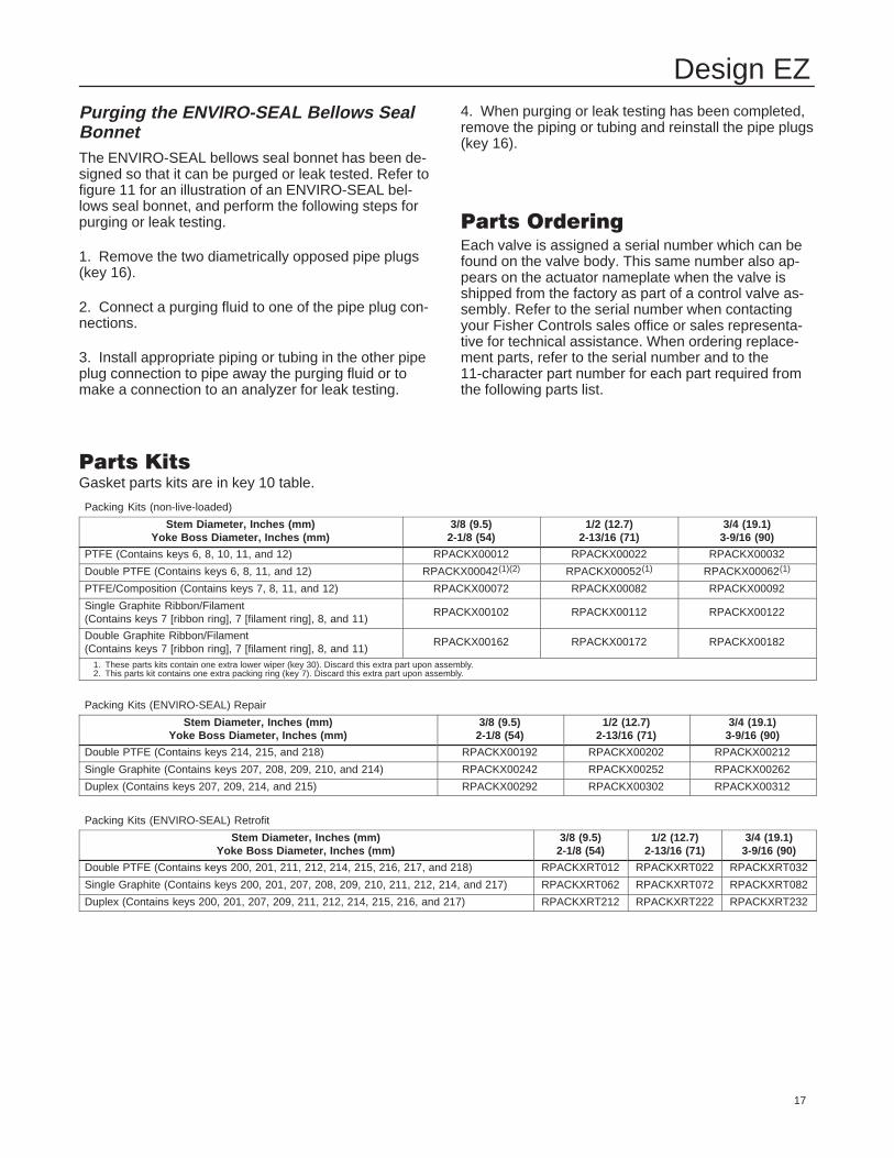
Purging the ENVIRO-SEAL Bellows SealBonnetThe ENVIRO-SEAL bellows seal bonnet has been de-signed so that it can be purged or leak tested. Refer tofigure 11 for an illustration of an ENVIRO-SEAL bel-lows seal bonnet, and perform the following steps forpurging or leak testing.
1. Remove the two diametrically opposed pipe plugs(key 16).
2. Connect a purging fluid to one of the pipe plug con-nections.
3. Install appropriate piping or tubing in the other pipeplug connection to pipe away the purging fluid or tomake a connection to an analyzer for leak testing.
4. When purging or leak testing has been completed,remove the piping or tubing and reinstall the pipe plugs(key 16).
����������
Each valve is assigned a serial number which can befound on the valve body. This same number also ap-pears on the actuator nameplate when the valve isshipped from the factory as part of a control valve as-sembly. Refer to the serial number when contactingyour Fisher Controls sales office or sales representa-tive for technical assistance. When ordering replace-ment parts, refer to the serial number and to the11-character part number for each part required fromthe following parts list.
���������Gasket parts kits are in key 10 table.
Packing Kits (non-live-loaded)
Stem Diameter, Inches (mm)Yoke Boss Diameter, Inches (mm)
3/8 (9.5)2-1/8 (54)
1/2 (12.7)2-13/16 (71)
3/4 (19.1)3-9/16 (90)
PTFE (Contains keys 6, 8, 10, 11, and 12) RPACKX00012 RPACKX00022 RPACKX00032
Double PTFE (Contains keys 6, 8, 11, and 12) RPACKX00042(1)(2) RPACKX00052(1) RPACKX00062(1)
PTFE/Composition (Contains keys 7, 8, 11, and 12) RPACKX00072 RPACKX00082 RPACKX00092
Single Graphite Ribbon/Filament(Contains keys 7 [ribbon ring], 7 [filament ring], 8, and 11)
RPACKX00102 RPACKX00112 RPACKX00122
Double Graphite Ribbon/Filament(Contains keys 7 [ribbon ring], 7 [filament ring], 8, and 11)
RPACKX00162 RPACKX00172 RPACKX00182
1. These parts kits contain one extra lower wiper (key 30). Discard this extra part upon assembly.2. This parts kit contains one extra packing ring (key 7). Discard this extra part upon assembly.
Packing Kits (ENVIRO-SEAL) Repair
Stem Diameter, Inches (mm)Yoke Boss Diameter, Inches (mm)
3/8 (9.5)2-1/8 (54)
1/2 (12.7)2-13/16 (71)
3/4 (19.1)3-9/16 (90)
Double PTFE (Contains keys 214, 215, and 218) RPACKX00192 RPACKX00202 RPACKX00212
Single Graphite (Contains keys 207, 208, 209, 210, and 214) RPACKX00242 RPACKX00252 RPACKX00262
Duplex (Contains keys 207, 209, 214, and 215) RPACKX00292 RPACKX00302 RPACKX00312
Packing Kits (ENVIRO-SEAL) Retrofit
Stem Diameter, Inches (mm)Yoke Boss Diameter, Inches (mm)
3/8 (9.5)2-1/8 (54)
1/2 (12.7)2-13/16 (71)
3/4 (19.1)3-9/16 (90)
Double PTFE (Contains keys 200, 201, 211, 212, 214, 215, 216, 217, and 218) RPACKXRT012 RPACKXRT022 RPACKXRT032
Single Graphite (Contains keys 200, 201, 207, 208, 209, 210, 211, 212, 214, and 217) RPACKXRT062 RPACKXRT072 RPACKXRT082
Duplex (Contains keys 200, 201, 207, 209, 211, 212, 214, 215, 216, and 217) RPACKXRT212 RPACKXRT222 RPACKXRT232

Design EZ
18
����������
BonnetKey Description Part Number
1 Bonnet/ENVIRO-SEAL bellows seal bonnetIf you need a bonnet or an ENVIRO-SEALbellows seal bonnet as a replacementpart, order by valve size and stemdiameter, serial number, and desiredmaterial.
2 Baffle,(for extension bonnets only) See following table3 Packing Flange, S31600 (316 SST)
2-1/8 inch (54 mm) yoke boss 1E9437350722-13/16 inch (71 mm) yoke boss 1F3803350723-9/16 inch (90 mm) yoke boss 1F380435072
3 ENVIRO-SEAL Bellows Seal Packing FlangeS31603For 3/8 inch (9.5 mm) stem and size 2w/ 1/2 inch (12.7 mm) stem 28A0827X012
Size 3 and 4 w/ 1/2 inch (12.7 mm) stem 28A0829X012N10276For 3/8 inch (9.5 mm) stem and size 2w/ 1/2 inch (12.7 mm) stem 28A0827X112
Size 3 and 4 w/ 1/2 inch (12.7 mm) stem 28A0829X1124 Packing Flange Stud, S31600 (2 req’d)
2-1/8 inch (54 mm) yoke boss 1E9441352222-13/16 (71 mm) yoke boss 1E9444352223-9/16 inch (90 mm) yoke boss 1E944935222
4 ENVIRO-SEAL Bellows Seal Stud BoltS316033/8 inch (9.5 mm) stem 1E944135222Size 2 w/ 1/2 inch (12.7 mm) stem 11B6951X072Size 3 and 4 w/ 1/2 inch (12.7 mm) stem 16A1061X022
N102763/8 inch (9.5 mm) stem 1E944140152Size 2 w/ 1/2 inch (12.7 mm) stem 11B6951X052Size 3 and 4 w/ 1/2 inch (12.7 mm) stem 16A1061X072
5 Packing Flange Nut, S31600 (2 req’d)2-1/8 inch (54 mm) yoke boss 1E9440352522-13/16 (71 mm) yoke boss 1E9445352523-9/16 inch (90 mm) yoke boss 1E944635252
5 ENVIRO-SEAL Bellows Seal Hex NutS31603For 3/8 inch (9.5 mm) stem and size 2w/ 1/2 inch (12.7 mm) stem 1E944035252
Size 3 and 4 w/ 1/2 inch (12.7 mm) stem 1A375335252N10276For 3/8 inch (9.5 mm) stem and size 2w/ 1/2 inch (12.7 mm) stem 1E944040152
Size 3 and 4 w/ 1/2 inch (12.7 mm) stem 1A3753X00626* Packing Set, PTFE (2 req’d for double packing)
3/8-inch (9.5 mm) stem 1R2900010121/2-inch (12.7 mm) stem 1R2902010123/4-inch (19.1 mm) stem 1R290401012
6* ENVIRO-SEAL Bellows Seal Packing SetPTFE for 3/8 inch (9.5 mm) stem (1 req’dfor single packing, 2 req’d for doublepacking) 12A9016X012
PTFE for size 2 with 1/2 inch (12.7 mm)stem (2 req’d for double packing) 12A9016X012
PTFE for size 3 and 4 with 1/2 inch12.7 mm) stem (2 req’d for doublepacking) 12A8832X012
6* Packing Set, PTFE/KALREZ3/8-inch (9.5 mm) stem 13B0963X0121/2-inch (12.7 mm) stem 13B0964X0123/4-inch (19.1 mm) stem 13B0965X012
Key Description Part Number7* Packing Ring, PTFE/comp (for
double packing)3/8-inch (9.5 mm) stemPTFE/comp (7 req’d) 1F3370X0012
1/2-inch (12.7 mm) stemPTFE/comp (10 req’d) 1E319001042
3/4-inch (19.1 mm) stemPTFE/comp (8 req’d) 1E319101042
7* Packing Ring, graphite ribbon ring (2 req’dfor single packing, 3 req’d for doublepacking)3/8-inch (9.5 mm) stem 1V3160X00221/2-inch (12.7 mm) stem 1V3802X00223/4-inch (19.1 mm) stem 1V2396X0022
7* Packing Ring, graphite filament ring3/8-inch (9.5 mm) stem (2 req’d for singlepacking, 4 req’d for double packing) 1F3370X03221/2-inch (12.7 mm) stem (3 req’d forsingle packing, 5 req’d for doublepacking) 1E3190X02223/4-inch (19.1 mm) stem (2 req’d forsingle packing, 4 req’d for doublepacking) 1E3191X0282
7* ENVIRO-SEAL Bellows Seal Packing Ringfor low chloride graphite ribbon/filamentpacking arrangementRibbon packing ring for 3/8 inch (9.5 mm)and size 2 with 1/2 inch (12.7 mm) stem(4 req’d) 18A0908X012
Filament packing ring for 3/8 inch(9.5 mm) and size 2 with 1/2 inch(12.7 mm) stem (4 req’d) 1P3905X0172
Ribbon packing ring for size 3 and 4with 1/2 inch (12.7 mm) stem (4 req’d) 18A0918X012
Filament packing ring for size 3 and 4with 1/2 inch (12.7 mm) stem (4 req’d) 14A0915X042
8 Spring, S31600 (for single PTFE packing only)3/8-inch (9.5 mm) stem 1F1254370121/2-inch (12.7 mm) stem 1F1255370123/4-inch (19.1 mm) stem 1F125637012
8 Spacer, N04400 (Monel) (for single PTFE packing only)(for Monel trim only)
3/8-inch (9.5 mm) stem 1F1318400321/2-inch (12.7 mm) stem 1F1317400123/4-inch (19.1 mm) stem 1F131640032
8 Lantern Ring (for double PTFE packing)3/8-inch (9.5 mm) stemS31600 (std for S31600 and S41600 trims) 1F364135072N04400 (std for N05500 trim) 1F364140032
1/2-inch (12.7 mm) stem (2 req’d)S31600 (std for S31600 and S41600 trims) 1J962335072N04400 (std for N05500 trim) 1J962340032
3/4-inch (19.1 mm) stemS31600 (std for S31600 and S41600 trims) 0N028435072N04400 (std for N05500 trim) 0N028440032
For PTFE/comp packing3/8-inch (9.5 mm) stemS31600 (std for S31600 and S41600 trims) 1F364135072N04400 (std for N05500 trim) 1F364140032
1/2-inch (12.7 mm) stemS31600 (std for S31600 and S41600 trims) 1J962335072N04400 (std for N05500 trim) 1J962340032
3/4-inch (19.1 mm) stemS31600 (std for S31600 and S41600 trims) 0N028435072N04400 (std for N05500 trim) 0N028440032
*Recommended spare parts

Design EZ
19
Figure 11. Typical Bonnets
CU3911–D/IL
42B3947–A/IL
AU3910–A/IL

Design EZ
20
Key Description Part Number8 Lantern Ring (cont’d)
For graphite ribbon/filament packing3/8-inch (9.5 mm) stem (2 req’d for singlepacking, 1 req’d for double packing)S31600 (std for S31600 and S41600 trims) 1F364135072N04400 (std for N05500 trim) 1F364140032
1/2-inch (12.7 mm) stem (3 req’d forsingle packing, 2 req’d for doublepacking)S31600 (std for S31600 and S41600 trims) 1J962335072N04400 (std for N05500 trim) 1J962340032
3/4-inch (19.1 mm) stem (2 req’d forsingle packing, 1 req’d for doublepacking)S31600 (std for S31600 and S41600 trims) 0N028435072N04400 (std for N05500 trim) 0N028440032
8 ENVIRO-SEAL Bellows Seal SpringFor 3/8 inch (9.5 mm) and size 2 with 1/2inch (12.7 mm) stem (for single packingonly) 1F125437012
8 ENVIRO-SEAL Bellows Seal Spacer for S31600(316 SST) constructionFor single PTFE packing size 2with 1/2 inch (12.7 mm) stem 18A0872X012
For double PTFE, graphite ribbon/filamentpacking 3/8 inch (9.5 mm) stem 18A0872X012Size 2 with 1/2 inch (12.7 mm) stem(2 req’d) 18A0872X012
Size 3 and 4 with 1/2 inch (12.7 mm)stem (2 req’d) 18A0874X012
8 ENVIRO-SEAL Bellows Seal Spacer for N10276(Hastelloy C) constructionFor single PTFE packing3/8 inch (9.5 mm) stem and size 2with 1/2 inch (12.7 mm) stem (1 req’d) 18A0872X032Size 2 with 1/2 inch stem (12.7 mm)stem only (1 req’d) 1H981540152
For double PTFE, graphite ribbon/filamentpacking 3/8 inch (9.5 mm) stem 18A0872X032Size 2 w/ 1/2 inch (12.7 mm) stem(2 req’d) 18A0872X032
Size 3 and 4 with 1/2 inch (12.7 mm)stem (2 req’d) 18A0874X032
10 Special Washer, S31600 (for single PTFEpacking)3/8-inch (9.5 mm) stem 1F1252360421/2-inch (12.7 mm) stem 1F1251360423/4-inch (19.1 mm) stem 1F125036042
11* Packing Box RingSingle PTFE packing3/8-inch (9.5 mm) stemS31600 (std for S31600 and S41600 trims) 1J873135072N05500 (std for N05500 trim) 1J873146222
1/2-inch (12.7 mm) stemS31600 (std for S31600 and S41600 trims) 1J873235072N05500 (std for N05500 trim) 1J873246222
3/4-inch (19.1 mm) stemS31600 (std for S31600 and S41600 trims) 1J873335072N05500 (std for N05500 trim) 1J873346222
Double PTFE packing3/8-inch (9.5 mm) stemS31600 (std for S31600 and S41600 trims) 1J873135072Glass-filled PTFE (std for N05500 trim) 17A6872X012
1/2-inch (12.7 mm) stemS31600 (std for S31600 and S41600 trims) 1J873235072Glass-filled PTFE (std for N05500 trim) 17A6873X012
Key Description Part Number11* Packing Box Ring (cont’d)
Double PTFE packing (cont’d)3/4-inch (19.1 mm) stemS31600 (std for S31600 and S41600 trims) 1J873335072Glass-filled PTFE (std for N05500 trim) 17A6874X012
PTFE/composition packing3/8-inch (9.5 mm) stemS31600 (std for S31600 and S41600 trims) 1J873135072Glass-filled PTFE (std for N05500 trim) 17A6872X012
1/2-inch (12.7 mm) stemS31600 (std for S31600 and S41600 trims) 1J873235072N05500 (std for N05500 trim) 1J873246222
3/4-inch (19.1 mm) stemS31600 (std for S31600 and S41600 trims) 1J873335072Glass-filled PTFE (std for N05500 trim) 17A6874X012
12* Upper Wiper, felt3/8-inch (9.5 mm) stem 1J8726063321/2-inch (12.7 mm) stem 1J8727063323/4-inch (19.1 mm) stem 1J872806332
12* ENVIRO-SEAL Bellows Seal Upper WiperFor 3/8 inch (9.5 mm) and size 2 with 1/2inch (12.7 mm) stem 18A0868X012
For size 3 and 4 with 1/2 inch (12.7 mm)stem 18A0870X012
13 Packing FollowerS31600 (std for all trims materials)3/8-inch (9.5 mm) stem 1E9439350721/2-inch (12.7 mm) stem 1E9443350723/4-inch (19.1 mm) stem 1E944735072
N04400 (optional for alloy trims)3/8-inch (9.5 mm) stem 1E9439400321/2-inch (12.7 mm) stem 1E9443400323/4-inch (19.1 mm) stem 1E944740032
13* ENVIRO-SEAL Bellows Seal BushingFor 3/8 inch (9.5 mm) stem (1 req’d),for size 2 with 1/2 inch (12.7 mm) stem(2 req’d)S31600/PTFE 18A0820X012R30006 18A0819X012S31600/Cr Ct 11B1155X012
For size 3 and 4 with 1/2 inch (12.7 mm)stem (1 req’d)S31600/PTFE 18A0824X012R30006 18A0823X012S31600/Cr Ct 11B1157X012
13* ENVIRO-SEAL Bellows Seal Bushing/LinerFor 3/8 inch (9.5 mm) stem (1 req’d),for size 2 with 1/2 inch (12.7 mm) stem(2 req’d)N10276 bushing, PTFE/glass liner 12B2713X012N10276 bushing, PTFE/carbon liner 12B2713X042
For size 3 and 4 with 1/2 inch (12.7 mm)stem (1 req’d)N10276 bushing, PTFE/glass liner 12B2715X012N10276 bushing, PTFE/carbon liner 12B2715X042
14 Pipe Plug (not shown)Steel bonnet 1A767524662CF8M bonnet 1A767535072
14 Lubricator 0V0873000A214 Lubricator/Isolating Valve AJ5428000A215 Yoke Locknut
2-1/8 inch (54 mm) yoke boss 1E7930230622-13/15 inch (71 mm) yoke boss 1E8074230623-9/16 inch (90 mm) yoke boss 1E832723062
15 ENVIRO-SEAL Bellows Seal Yoke Locknut2-1/8 inch (54 mm) yoke boss 1E7930230622-13/16 inch (71 mm) yoke boss 1E807423062
*Recommended spare parts

Design EZ
21
Key Description Part Number16 Pipe Plug (not shown)
Steel 1A369224492S31600 1A369235072
16 ENVIRO-SEAL Bellows Seal Pipe Plug(2 req’d)WCB 1A767524662CF3M (316 SST) 1A767535072CW2M (Hastelloy C) 1A767540152CN7M (Alloy 20) 1A767540092M35-1 (Monel) 1A767540012
20* ENVIRO-SEAL Bellows Seal Stem/BellowsAssembly1 Ply BellowsS31603 trim mat’l, N06625 bellows mat’lSize 1 w/ 3/8 inch (9.5 mm) stem 32B4224X012Size 1-1/2 w/ 3/8 inch (9.5 mm) stem 32B4225X012Size 2 w/ 1/2 inch (12.7 mm) stem 32B4226X012Size 3 w/ 1/2 inch (12.7 mm) stem 32B4227X012Size 4 w/ 1/2 inch (12.7 mm) stem 32B4228X012
N06022 trim mat’l, N06022 bellows mat’lSize 1 w/ 3/8 inch (9.5 mm) stem 32B4224X022Size 1-1/2 w/ 3/8 inch (9.5 mm) stem 32B4225X022Size 2 w/ 1/2 inch (12.7 mm) stem 32B4226X022Size 3 w/ 1/2 inch (12.7 mm) stem 32B4227X022Size 4 w/ 1/2 inch (12.7 mm) stem 32B4228X022
2 Ply BellowsS31603 trim mat’l, N06625 bellows mat’lSize 1 w/ 3/8 inch (9.5 mm) stem 32B4224X032Size 1-1/2 w/ 3/8 inch (9.5 mm) stem 32B4225X032Size 2 w/ 1/2 inch (12.7 mm) stem 32B4226X032Size 3 w/ 1/2 inch (12.7 mm) stem 32B4227X032Size 4 w/ 1/2 inch (12.7 mm) stem 32B4228X032
N06022 trim mat’l, N06022 bellows mat’lSize 1 w/ 3/8 inch (9.5 mm) stem 32B4224X042Size 1-1/2 w/ 3/8 inch (9.5 mm) stem 32B4225X042Size 2 w/ 1/2 inch (12.7 mm) stem 32B4226X042Size 3 w/ 1/2 inch (12.7 mm) stem 32B4227X042Size 4 w/ 1/2 inch (12.7 mm) stem 32B4228X042
22* ENVIRO-SEAL Bellows Seal Bonnet Gasket(graphite/S31600)Size 1/2 through 1-1/4 12B6316X022Size 1-1/2 12B6317X022Size 2 12B6318X022Size 3 12B6319X022Size 4 12B6320X022
24 ENVIRO-SEAL Bellows Seal AdaptorS31603Size 1/2 through 1-1/2 Micro-Flow andMicro-Flute w/metal seat 22B4259X012
Size 1/2 through 1-1/2 Micro-Flute andMicro-Form w/1/4 through 3/8 inch portand composition seats 22B4258X012
Size 1/2 through 1-1/2 w/full port andcomposition seat, and
Size 1/2 through 1-1/2 Micro-Form with1/2 through 3/4 inch port andcomposition seat 22B4260X012
Size 1/2 through 1-1/2 w/full port andmetal seat, and
Size 1/2 through 1-1/2 Micro-Form withmetal seat 22B4249X012
Size 2 Micro-Flow w/metal seat, andSize 2 Micro-Flute w/metal andcomposition seats, and
Size 2 Micro-Form w/1/4-inch port andcomposition seat 22B4266X012
Key Description Part Number24 ENVIRO-SEAL Bellows Seal Adaptor (cont’d)
S31603 (cont’d)Sizes 2, 3, and 4 full port w/metal andcomposition seats 22B4251X012
Size 2 Micro-Form w/1/4 through 3/4-inchport and metal seat, and
Size 2 Micro-Form w/3/8 through 3/4-inchport and composition seat, and
Size 2 restricted port w/metal andcomposition seats 22B4256X012
Size 3 restricted port w/metal seat 22B4257X012Size 4 restricted port w/metal seat 22B4253X012
N10276Size 1/2 through 1-1/2 Micro-Flow andMicro-Flute w/metal seat 22B4259X022
Size 1/2 through 1-1/2 Micro-Flute andMicro-Form w/1/4 through 3/8 inch portand composition seats 22B4258X022
Size 1/2 through 1-1/4 w/full port andcomposition seat, and
Size 1/2 through 1-1/2 Micro-Form with1/2 through 3/4 inch port andcomposition seat, and
Size 1-1/2 w/full & restricted port andcomposition seat 22B4260X022
Size 1/2 through 1-1/4 w/full port andmetal seat, and
Size 1/2 through 1-1/2 Micro-Form withmetal seat, and
Size 1-1/2 full & restricted port withmetal seat 22B4249X022
Size 2 Micro-Flow w/metal seat, andSize 2 Micro-Flute w/metal andcomposition seats, and
Size 2 Micro-Form w/1/4-inch port andcomposition seat 22B4266X022
Sizes 2, 3, and 4 full port w/metal andcomposition seats 22B4251X022
Size 2 Micro-Form w/1/4 through 3/4-inchport and metal seat, and
Size 2 Micro-Form w/3/8 through 3/4-inchport and composition seat, and
Size 2 restricted port w/metal andcomposition seats 22B4256X022
Size 3 restricted port w/metal seat 22B4257X022Size 4 restricted port w/metal seat 22B4253X022
27 Pipe Nipple, for lub/isolating valve,steel 1N62402623228 ENVIRO-SEAL Bellows Seal Nameplate, Warning 1E5174X00A229 ENVIRO-SEAL Bellows Seal Drive Screw
(2 req’d) 1A36822898234 Lubricant, Never-Seez Nickel Special
or equivalent (not furnished with valve) ---36* ENVIRO-SEAL Bellows Seal Pin 12B3951X01237 ENVIRO-SEAL Bellows Seal Warning Tag 22B3975X01238 ENVIRO-SEAL Bellows Seal Tie 18A9401X01239 ENVIRO-SEAL Bellows Seal Thrust Ring
For 3/8 inch (9.5 mm) stemFor use with S31600 trim (3 req’d forsingle PTFE packing, 1 req’d for doublePTFE and graphite/ribbon packing) 19A9208X112
For use with N10276 trim (1 req’d forPTFE and graphite ribbon packing) 19A9208X022
For 1/2 inch (12.7 mm) stemFor use with S31600 trim (2 req’d forsingle PTFE packing) 19A9208X112
*Recommended spare parts
Design EZ
22
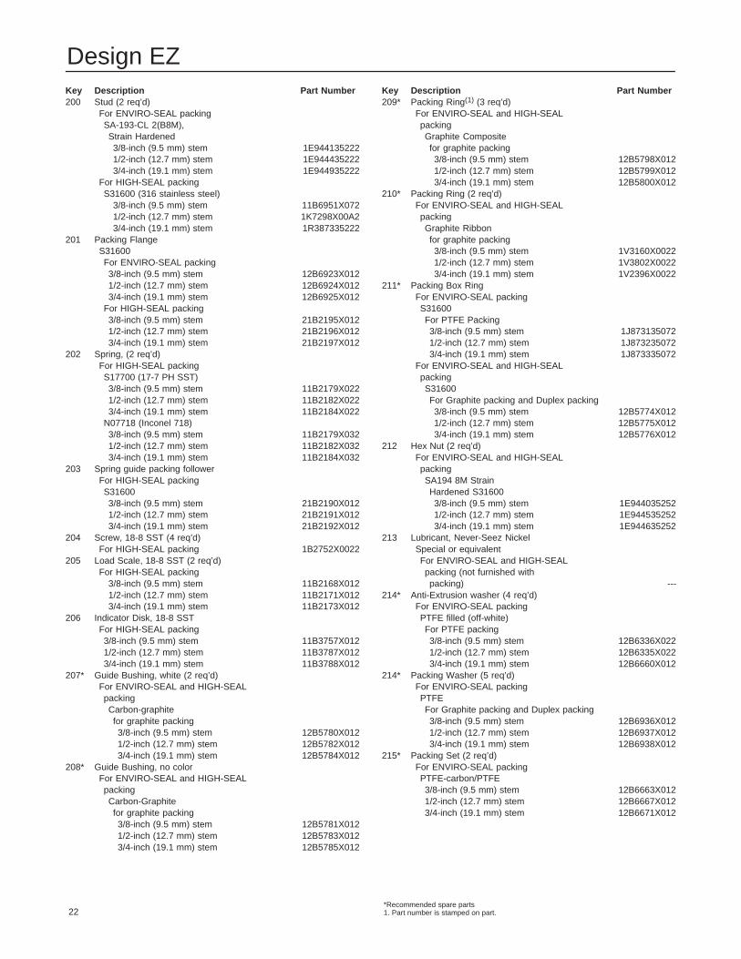
Key Description Part Number200 Stud (2 req’d)
For ENVIRO-SEAL packingSA-193-CL 2(B8M),Strain Hardened3/8-inch (9.5 mm) stem 1E9441352221/2-inch (12.7 mm) stem 1E9444352223/4-inch (19.1 mm) stem 1E944935222
For HIGH-SEAL packingS31600 (316 stainless steel)
3/8-inch (9.5 mm) stem 11B6951X0721/2-inch (12.7 mm) stem 1K7298X00A23/4-inch (19.1 mm) stem 1R387335222
201 Packing FlangeS31600For ENVIRO-SEAL packing3/8-inch (9.5 mm) stem 12B6923X0121/2-inch (12.7 mm) stem 12B6924X0123/4-inch (19.1 mm) stem 12B6925X012
For HIGH-SEAL packing3/8-inch (9.5 mm) stem 21B2195X0121/2-inch (12.7 mm) stem 21B2196X0123/4-inch (19.1 mm) stem 21B2197X012
202 Spring, (2 req’d)For HIGH-SEAL packingS17700 (17-7 PH SST)3/8-inch (9.5 mm) stem 11B2179X0221/2-inch (12.7 mm) stem 11B2182X0223/4-inch (19.1 mm) stem 11B2184X022
N07718 (Inconel 718)3/8-inch (9.5 mm) stem 11B2179X0321/2-inch (12.7 mm) stem 11B2182X0323/4-inch (19.1 mm) stem 11B2184X032
203 Spring guide packing followerFor HIGH-SEAL packingS316003/8-inch (9.5 mm) stem 21B2190X0121/2-inch (12.7 mm) stem 21B2191X0123/4-inch (19.1 mm) stem 21B2192X012
204 Screw, 18-8 SST (4 req’d)For HIGH-SEAL packing 1B2752X0022
205 Load Scale, 18-8 SST (2 req’d)For HIGH-SEAL packing
3/8-inch (9.5 mm) stem 11B2168X0121/2-inch (12.7 mm) stem 11B2171X0123/4-inch (19.1 mm) stem 11B2173X012
206 Indicator Disk, 18-8 SSTFor HIGH-SEAL packing3/8-inch (9.5 mm) stem 11B3757X0121/2-inch (12.7 mm) stem 11B3787X0123/4-inch (19.1 mm) stem 11B3788X012
207* Guide Bushing, white (2 req’d)For ENVIRO-SEAL and HIGH-SEALpackingCarbon-graphitefor graphite packing3/8-inch (9.5 mm) stem 12B5780X0121/2-inch (12.7 mm) stem 12B5782X0123/4-inch (19.1 mm) stem 12B5784X012
208* Guide Bushing, no colorFor ENVIRO-SEAL and HIGH-SEALpackingCarbon-Graphitefor graphite packing3/8-inch (9.5 mm) stem 12B5781X0121/2-inch (12.7 mm) stem 12B5783X0123/4-inch (19.1 mm) stem 12B5785X012
Key Description Part Number209* Packing Ring(1) (3 req’d)
For ENVIRO-SEAL and HIGH-SEALpackingGraphite Compositefor graphite packing3/8-inch (9.5 mm) stem 12B5798X0121/2-inch (12.7 mm) stem 12B5799X0123/4-inch (19.1 mm) stem 12B5800X012
210* Packing Ring (2 req’d)For ENVIRO-SEAL and HIGH-SEALpackingGraphite Ribbonfor graphite packing3/8-inch (9.5 mm) stem 1V3160X00221/2-inch (12.7 mm) stem 1V3802X00223/4-inch (19.1 mm) stem 1V2396X0022
211* Packing Box RingFor ENVIRO-SEAL packingS31600For PTFE Packing3/8-inch (9.5 mm) stem 1J8731350721/2-inch (12.7 mm) stem 1J8732350723/4-inch (19.1 mm) stem 1J873335072
For ENVIRO-SEAL and HIGH-SEALpackingS31600For Graphite packing and Duplex packing3/8-inch (9.5 mm) stem 12B5774X0121/2-inch (12.7 mm) stem 12B5775X0123/4-inch (19.1 mm) stem 12B5776X012
212 Hex Nut (2 req’d)For ENVIRO-SEAL and HIGH-SEALpackingSA194 8M StrainHardened S316003/8-inch (9.5 mm) stem 1E9440352521/2-inch (12.7 mm) stem 1E9445352523/4-inch (19.1 mm) stem 1E944635252
213 Lubricant, Never-Seez NickelSpecial or equivalentFor ENVIRO-SEAL and HIGH-SEALpacking (not furnished withpacking) ---
214* Anti-Extrusion washer (4 req’d)For ENVIRO-SEAL packingPTFE filled (off-white)For PTFE packing3/8-inch (9.5 mm) stem 12B6336X0221/2-inch (12.7 mm) stem 12B6335X0223/4-inch (19.1 mm) stem 12B6660X012
214* Packing Washer (5 req’d)For ENVIRO-SEAL packingPTFEFor Graphite packing and Duplex packing3/8-inch (9.5 mm) stem 12B6936X0121/2-inch (12.7 mm) stem 12B6937X0123/4-inch (19.1 mm) stem 12B6938X012
215* Packing Set (2 req’d)For ENVIRO-SEAL packingPTFE-carbon/PTFE3/8-inch (9.5 mm) stem 12B6663X0121/2-inch (12.7 mm) stem 12B6667X0123/4-inch (19.1 mm) stem 12B6671X012
*Recommended spare parts1. Part number is stamped on part.
Design EZ
23
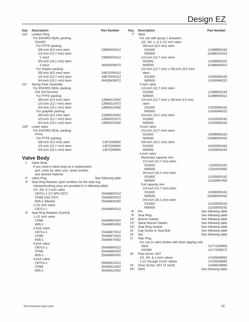
Key Description Part Number216 Lantern Ring
For ENVIRO-SEAL packingS31600For PTFE packing3/8-inch (9.5 mm) stem 22B6943X0121/2-inch (12.7 mm) stem1 req’d 22B6944X012
3/4-inch (19.1 mm) stem2 req’d 0N028435072
For Duplex packing3/8-inch (9.5 mm) stem 24B7529X0121/2-inch (12.7 mm) stem 24B7530X0123/4-inch (19.1 mm) stem 0N028435072
217 Spring Pack AssemblyFor ENVIRO-SEAL packing316 SST/InconelFor PTFE packing3/8-inch (9.5 mm) stem 12B6921X0621/2-inch (12.7 mm) stem 12B6921X0723/4-inch (19.1 mm) stem 12B6921X082
For graphite packing3/8-inch (9.5 mm) stem 12B6922X0621/2-inch (12.7 mm) stem 12B6922X0723/4-inch (19.1 mm) stem 12B6922X082
218* Lower wiperFor ENVIRO-SEAL packingPTFEFor PTFE packing3/8-inch (9.5 mm) stem 1J8721069921/2-inch (12.7 mm) stem 1J8722069923/4-inch (19.1 mm) stem 1J872306992
Valve Body1 Valve Body
If you need a valve body as a replacementpart, order by valve size, serial number,and desired material.
2* Valve Plug See following table3* Seat Ring Retainer (part numbers for the seat ring
retainer/bushing assy are provided in a following table)1/2, 3/4, & 1-inch valveCB7Cu-1 (17-4PH SST) 25A6683X012CF8M (316 SST) 25A6683X022M35-1 (Monel) 25A6683X052
1-1/2 inch valveCB7Cu-1 25A6685X012
3* Seat Ring Retainer (Cont’d)1-1/2 inch valveCF8M 25A6685X022M35-1 25A6685X052
2-inch valveCB7Cu-1 25A6687X012CF8M 25A6687X022M35-1 25A6687X052
3-inch valveCB7Cu-1 25A6689X012CF8M 25A6689X022M35-1 25A6689X052
4-inch valveCB7Cu-1 35A6691X012CF8M 35A6691X022M35-1 35A6691X052
Key Description Part Number7* Stem
For use with group 1 actuators1/2, 3/4, 1, & 1-1/2 inch valve3/8-inch (9.5 mm) stemS31600 1U388835162N05500 10A8823XA22
1/2-inch (12.7 mm) stemS31600 1U388935162N05500 1U3889X0012
1/2-inch (12.7 mm) x 3/8-inch (9.5 mm)stemS31600 1U530935162N05500 1U530946222
2-inch valve1/2-inch (12.7 mm) stemS31600 1U388935162N05500 1U3889X0012
1/2-inch (12.7 mm) x 3/8-inch 9.5 mm)stemS31600 1U530935162N05500 1U530946222
3/4-inch (19.1 mm) stemS31600 1U226535162N05500 1U226550192
3-inch valve1/2-inch (12.7 mm) stemS31600 1K586935162N05500 10A8840XH32
3/4-inch (19.1 mm) stemS31600 10A9265XJ62N05500 1U226550192
4-inch valveRestricted capacity trim1/2-inch (12.7 mm) stemS31600 1J320535162N05500 1J3205X0062
3/4-inch (19.1 mm) stemS31600 1U230835162N05500 1U230847492
Full capacity trim1/2-inch (12.7 mm) stemS31600 1K586935162N05500 10A8840XH32
3/4-inch (19.1 mm) stemS31600 1U226535162N05500 1U226550192
8* Pin See following table9* Seat Ring See following table
10* Bonnet Gasket See following table12* Spiral Wound Gasket See following table13* Seat Ring Gasket See following table15 Cap Screw or Stud Bolt See following table16 Nut See following table17 Pipe Plug
For use in valve bodies with drain tapping onlySteel 1A771528992S31600 1A771535072
18 Flow Arrow, SST1/2, 3/4, & 1-inch valves 1V1059389821-1/2 through 4-inch valves 1V106038982
19 Drive Screw, SST (4 req’d) 1A36822898225* Shim See following table
*Recommended spare parts
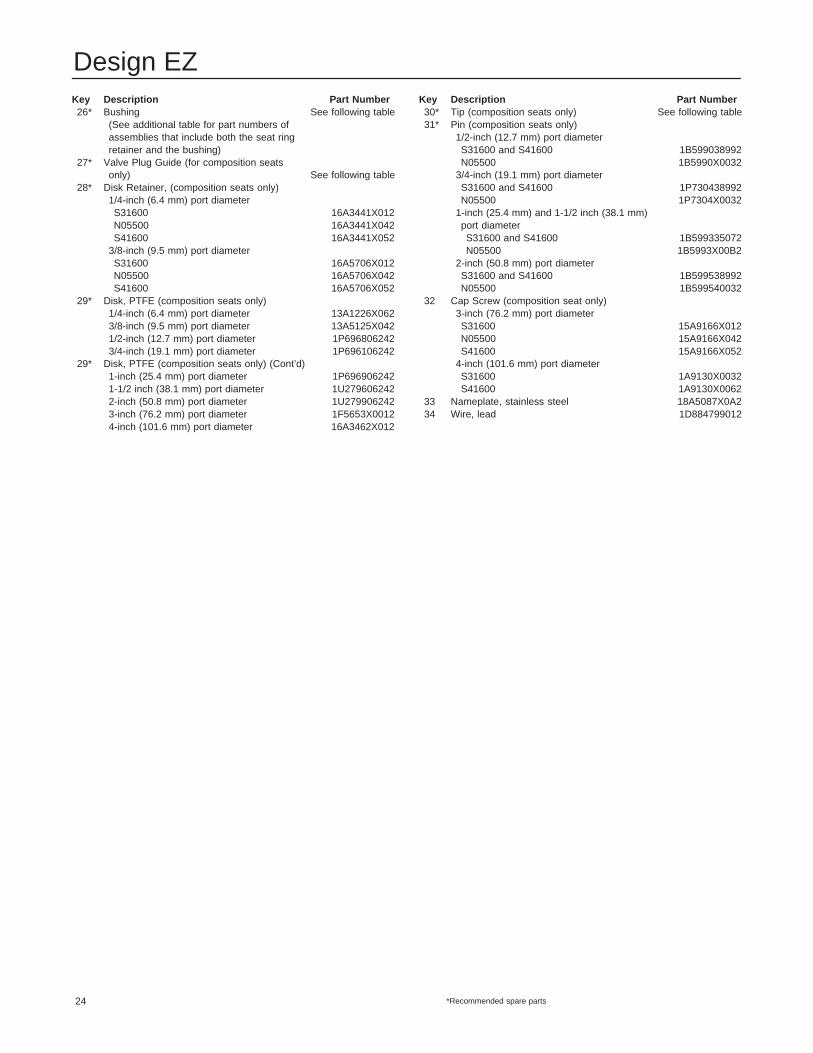
Design EZ
24
Key Description Part Number26* Bushing See following table
(See additional table for part numbers ofassemblies that include both the seat ringretainer and the bushing)
27* Valve Plug Guide (for composition seatsonly) See following table
28* Disk Retainer, (composition seats only)1/4-inch (6.4 mm) port diameterS31600 16A3441X012N05500 16A3441X042S41600 16A3441X052
3/8-inch (9.5 mm) port diameterS31600 16A5706X012N05500 16A5706X042S41600 16A5706X052
29* Disk, PTFE (composition seats only)1/4-inch (6.4 mm) port diameter 13A1226X0623/8-inch (9.5 mm) port diameter 13A5125X0421/2-inch (12.7 mm) port diameter 1P6968062423/4-inch (19.1 mm) port diameter 1P696106242
29* Disk, PTFE (composition seats only) (Cont’d)1-inch (25.4 mm) port diameter 1P6969062421-1/2 inch (38.1 mm) port diameter 1U2796062422-inch (50.8 mm) port diameter 1U2799062423-inch (76.2 mm) port diameter 1F5653X00124-inch (101.6 mm) port diameter 16A3462X012
Key Description Part Number30* Tip (composition seats only) See following table31* Pin (composition seats only)
1/2-inch (12.7 mm) port diameterS31600 and S41600 1B599038992N05500 1B5990X0032
3/4-inch (19.1 mm) port diameterS31600 and S41600 1P730438992N05500 1P7304X0032
1-inch (25.4 mm) and 1-1/2 inch (38.1 mm)port diameterS31600 and S41600 1B599335072N05500 1B5993X00B2
2-inch (50.8 mm) port diameterS31600 and S41600 1B599538992N05500 1B599540032
32 Cap Screw (composition seat only)3-inch (76.2 mm) port diameterS31600 15A9166X012N05500 15A9166X042S41600 15A9166X052
4-inch (101.6 mm) port diameterS31600 1A9130X0032S41600 1A9130X0062
33 Nameplate, stainless steel 18A5087X0A234 Wire, lead 1D884799012
*Recommended spare parts
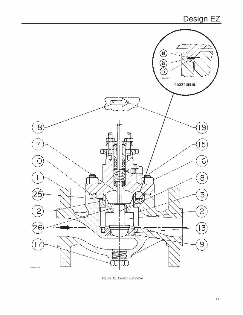
Design EZ
25
Figure 12. Design EZ Valve
35A5717–E/IL
16A1943–A

Design EZ
26
Figure 13. Composition Seats for Design EZ Valve46A1842–B

Design EZ
27
Figure 14. PTFE Packing Arrangements for ENVIRO-SEAL Bellows Seal Bonnets
A5886–1/IL
A5885/IL

Design EZ
28
Figure 15. Double Graphite Ribbon/Filament Arrangementsfor ENVIRO-SEAL Bellows Seal Bonnets
A5887–1/IL
Key 2 Extension Bonnet Baffle
VALVE SIZESTEM STYLE 1 EXTENSION STYLE 2 EXTENSION
VALVE SIZE,INCH
STEMDIAMETER Bonnet Material Bonnet Material
INCHInch mm Steel CF8M (316 SST) Steel CF8M
1/2, 3/4, 1, & 1-1/2 3/81/2
9.512.7
10A2910X01210A2909X012
10A2910X03210A2909X032
10A2910X01210A2909X012
10A2910X03210A2909X032
1-1/2 3/4 19.1 10A2907X012 10A2907X032 - - - - - -
2 1/23/4
12.719.1
10A2909X0121R351824492
10A2909X0321R351835072
1R3360244921R351824492
1R3360350721R351835072
3 1/23/4
12.719.1
10A2908X0121R351824492
10A2908X0321R351835072
1R3360244921R351824492
1R3360350721R351835072
4 1/23/4
12.719.1
10A2908X0121R351824492
10A2908X0321R351835072
1R3586244921R371324492
1R3586350721R371335072
Key 2* Micro-Flow and Micro-Flute Valve Plug
VALVEPORT
DIAMETERVALVE STEMCONNECTION
VALVE PLUG MATERIALVALVESIZE, VALVE
PLUGDIAMETER CONNECTION S31600 (316 SST)
N05500 S41600SIZE,INCH PLUG
Inch mm Inch mm
S31600 (316 SST)w/R30006 (Alloy 6)
Seat & Tip
N05500(K-Monel)
S41600(416 SST)
1/2, 3/4, 1,1-1/2, 2
Micro-FlowMicro-Flute (1 flute)Micro-Flute (3 flutes)
3/161/41/4
4.86.46.4
3/8 9.52V9269503322U8682464222U868446422
1V1081462221U8445462221U844746222
1V1081461721U8445461721U844746172
*Recommended spare parts
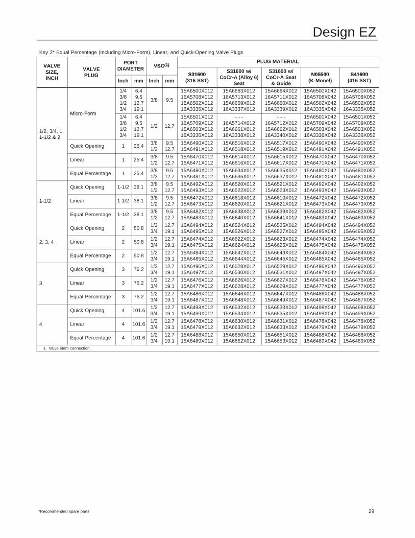
Design EZ
29
Key 2* Equal Percentage (Including Micro-Form), Linear, and Quick-Opening Valve Plugs
VALVEPORT
DIAMETER VSC(1)PLUG MATERIAL
VALVESIZE, VALVE
PLUGDIAMETER VSC(1)
S31600S31600 w/ S31600 w/
N05500 S41600SIZE,INCH PLUG
Inch mm Inch mmS31600
(316 SST)
S31600 w/CoCr-A (Alloy 6)
Seat
S31600 w/CoCr-A Seat
& Guide
N05500(K-Monel)
S41600(416 SST)
Micro Form
1/43/81/23/4
6.49.5
12.719.1
3/8 9.5
15A6500X01216A5708X01215A6502X01216A3335X012
15A6663X01216A5713X01215A6659X01216A3337X012
15A6664X01216A5711X01215A6660X01216A3339X012
15A6500X04216A5708X04215A6502X04216A3335X042
15A6500X05216A5708X05215A6502X05216A3335X052
1/2, 3/4, 1,1-1/2 & 2
Micro-Form1/43/81/23/4
6.49.5
12.719.1
1/2 12.7
15A6501X01216A5709X01215A6503X01216A3336X012
- - -16A5714X01215A6661X01216A3338X012
- - -16A5712X01215A6662X01216A3340X012
15A6501X04216A5709X04215A6503X04216A3336X042
15A6501X05216A5709X05215A6503X05216A3336X0521-1/2 & 2
Quick Opening 1 25.4 3/81/2
9.512.7
15A6490X01215A6491X012
15A6516X01215A6518X012
15A6517X01215A6519X012
15A6490X04215A6491X042
15A6490X05215A6491X052
Linear 1 25.4 3/81/2
9.512.7
15A6470X01215A6471X012
15A6614X01215A6616X012
15A6615X01215A6617X012
15A6470X04215A6471X042
15A6470X05215A6471X052
Equal Percentage 1 25.4 3/81/2
9.512.7
15A6480X01215A6481X012
15A6634X01215A6636X012
15A6635X01215A6637X012
15A6480X04215A6481X042
15A6480X05215A6481X052
Quick Opening 1-1/2 38.1 3/81/2
9.512.7
15A6492X01215A6493X012
15A6520X01215A6522X012
15A6521X01215A6523X012
15A6492X04215A6493X042
15A6492X05215A6493X052
1-1/2 Linear 1-1/2 38.1 3/81/2
9.512.7
15A6472X01215A6473X012
15A6618X01215A6620X012
15A6619X01215A6621X012
15A6472X04215A6473X042
15A6472X05215A6473X052
Equal Percentage 1-1/2 38.1 3/81/2
9.512.7
15A6482X01215A6483X012
15A6638X01215A6640X012
15A6639X01215A6641X012
15A6482X04215A6483X042
15A6482X05215A6483X052
Quick Opening 2 50.8 1/23/4
12.719.1
15A6494X01215A6495X012
15A6524X01215A6526X012
15A6525X01215A6527X012
15A6494X04215A6495X042
15A6494X05215A6495X052
2, 3, 4 Linear 2 50.8 1/23/4
12.719.1
15A6474X01215A6475X012
15A6622X01215A6624X012
15A6623X01215A6625X012
15A6474X04215A6475X042
15A6474X05215A6475X052
Equal Percentage 2 50.8 1/23/4
12.719.1
15A6484X01215A6485X012
15A6642X01215A6644X012
15A6643X01215A6645X012
15A6484X04215A6485X042
15A6484X05215A6485X052
Quick Opening 3 76.2 1/23/4
12.719.1
15A6496X01215A6497X012
15A6528X01215A6530X012
15A6529X01215A6531X012
15A6496X04215A6497X042
15A6496X05215A6497X052
3 Linear 3 76.2 1/23/4
12.719.1
15A6476X01215A6477X012
15A6626X01215A6628X012
15A6627X01215A6629X012
15A6476X04215A6477X042
15A6476X05215A6477X052
Equal Percentage 3 76.2 1/23/4
12.719.1
15A6486X01215A6487X012
15A6646X01215A6648X012
15A6647X01215A6649X012
15A6486X04215A6487X042
15A6486X05215A6487X052
Quick Opening 4 101.6 1/23/4
12.719.1
15A6498X01215A6499X012
15A6532X01215A6534X012
15A6533X01215A6535X012
15A6498X04215A6499X042
15A6498X05215A6499X052
4 Linear 4 101.6 1/23/4
12.719.1
15A6478X01215A6479X012
15A6630X01215A6632X012
15A6631X01215A6633X012
15A6478X04215A6479X042
15A6478X05215A6479X052
Equal Percentage 4 101.6 1/23/4
12.719.1
15A6488X01215A6489X012
15A6650X01215A6652X012
15A6651X01215A6653X012
15A6488X04215A6489X042
15A6488X05215A6489X052
1. Valve stem connection.
*Recommended spare parts
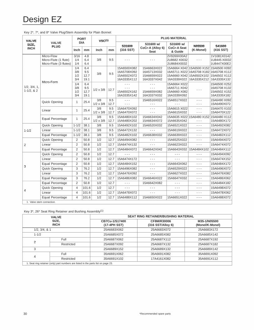
Design EZ
30
Key 2*, 7*, and 8* Valve Plug/Stem Assembly for Plain Bonnet
VALVEPORTDIA VSC(1)
PLUG MATERIALVALVESIZE, VALVE
PLUGDIA VSC(1)
S31600S31600 w/ S31600 w/
N05500 S41600SIZE,INCH PLUG
Inch mm Inch mmS31600
(316 SST)
S31600 w/CoCr-A (Alloy 6)
Seat
S31600 w/CoCr-A Seat
& Guide
N05500(K-Monel)
S41600(416 SST)
Micro-FlowMicro-Flute (1 flute)Micro-Flute (3 flutes)
3/161/41/4
4.86.46.4
3/8 9.5 - - - - - -2V9269X00A22U8682 X00322U8684X0032
- - -1V1081X01421U8445 X00321U8447X00E2
Micro Form
1/43/81/23/4
6.49.5
12.719.1
3/8 9.5
15A6500X08216A5708X09215A6502X07216A3335X112
15A6663X02216A5713X03215A6659X02216A3337X042
15A6664 X04216A5711 X02215A6660 X04216A3339X022
15A6500 X15216A5708 X18215A6502X10216A3335X212
15A6500 X09216A5708 X11215A6502 X11216A3335X132
1/2, 3/4, 1,1-1/2, & 2
Micro-Form1/43/81/23/4
6.49.5
12.719.1
1/2 x 3/8 12.7
- - -- - -
15A6502X16216A3335X142
- - -- - -
15A6659X08216A3337X032
15A6664 X02216A5711 X04215A6660 X08216A3339X092
- - -
15A6500 X25216A5708 X13215A6502 X15216A3335X182
Quick Opening 1 25.4 3/81/2 x 3/8
9.512.7
- - -- - -
15A6516X022- - -
15A6517X022- - -
- - -- - -
15A6490 X09215A6490X072
Linear 1 25.4 3/81/2 x 3/8
9.512.7
15A6470X09215A6470X072
- - -- - -
15A6615 X02215A6615X032
- - -- - -
15A6470 X10215A6470X122
Equal Percentage 1 25.4 3/81/2 x 3/8
9.512.7
15A6480X10215A6480X202
15A6634X04215A6634X072
15A6635 X02215A6635X042
15A6480 X152- - -
15A6480 X11215A6480X172
Quick Opening 1-1/2 38.1 3/8 9.5 15A6492X102 15A6520X032 15A6521X022 - - - 15A6492X082
1-1/2 Linear 1-1/2 38.1 3/8 9.5 15A6472X132 - - - 15A6619X022 - - - 15A6472X0721 1/2Equal Percentage 1-1/2 38.1 3/8 9.5 15A6482X102 15A6638X032 15A6639X022 - - - 15A6482X112
Quick Opening 2 50.8 1/2 12.7 15A6494X082 - - - 15A6525X022 - - - 15A6494X072
2 Linear 2 50.8 1/2 12.7 15A6474X132 - - - 15A6623X022 - - - 15A6474X0722Equal Percentage 2 50.8 1/2 12.7 15A6484X072 15A6642X042 15A6643X032 15A6484X102 15A6484X112
Quick Opening 2 50.8 1/2 12.7 - - - - - - - - - - - - 15A6494X092
Linear 2 50.8 1/2 12.7 15A6474X172 - - - - - - - - - 15A6474X152
3Equal Percentage 2 50.8 1/2 12.7 15A6484X152 - - - 15A6643X062 - - - 15A6484X172
3Quick Opening 3 76.2 1/2 12.7 15A6496X082 - - - 15A6529X022 - - - 15A6496X072
Linear 3 76.2 1/2 12.7 15A6476X092 - - - 15A6627X022 - - - 15A6476X082
Equal Percentage 3 76.2 1/2 12.7 15A6486X082 15A6646X022 15A6647X032 - - - 15A6486X062
Equal Percentage 2 50.8 1/2 12.7 - - - 15A6642X082 - - - - - - 15A6484X182
4Quick Opening 4 101.6 1/2 12.7 - - - - - - - - - - - - 15A6498X072
4Linear 4 101.6 1/2 12.7 15A6478X072 - - - - - - - - - 15A6478X062
Equal Percentage 4 101.6 1/2 12.7 15A6488X112 15A6650X022 15A6651X022 - - - 15A6488X0721. Valve stem connection.
Key 3*, 26* Seat Ring Retainer and Bushing Assembly(1)
VALVE SEAT RING RETAINER/BUSHING MATERIALVALVESIZE,INCH
CB7Cu-1/S17400(17-4PH SST)
CF8M/R30006(316 SST/Alloy 6)
M35-1/N05500(Monel/K-Monel)
1/2, 3/4, & 1 25A6683X062 25A6683X072 25A6683X172
1-1/2 25A6685X072 25A6685X082 25A6685X142
2Full 25A6687X062 25A6687X112 25A6687X192
2Restricted 25A6687X092 25A6687X132 25A6687X182
3 25A6689X152 25A6689X132 25A6689X142
4Full 35A6691X062 35A6691X082 35A6691X092
4Restricted 35A6691X102 17A4161X082 35A6691X112
1. Seat ring retainer (only) part numbers are listed in the parts list on page 23.
*Recommended spare parts

Design EZ
31
Key 8* Pin
VALVE SIZE,VALVE PLUG STYLE
VSC(1) PIN MATERIALVALVE SIZE,INCH VALVE PLUG STYLE
Inch mm S31600 (316 SST) N04400 (Monel)
1/2 thru 2
Micro-Flow & Micro-Flute w/metal seats
3/8 9.5 1B599235072 1B599240032
1/2 thru 2Micro-Flute w/comp seats &Micro-Form
3/81/2
9.512.7
1B5993350721D5423X00B2
1B5993X00B21D5423X0012
1/2 thru 1-1/2 Linear, Equal Percentage &Quick Opening
3/81/2
9.512.7
1B5993350721D5423X00B2
1B5993X00B21D5423X0012
2
Linear, Equal Percentage &Quick Opening (full cap)
1/23/4
12.719.1
1B5998350721B813635072
1B5998400321B8136X0102
2Linear, Equal Percentage &Quick Opening (restricted port)
3/81/2
9.512.7
1B5993350721D5423X00B2
1B5993X00B21D5423X0012
3 All 1/23/4
12.719.1
1B5998350721B813635072
1B5998400321B8136X0102
4
Full Capacity 1/23/4
12.719.1
1B5998350721B813635072
1B5998X00C21B8136X0102
4Restricted 1/2
3/412.719.1
1B5993350721F723635072
1B5993X00B21B813640032
1. Valve stem connection.
Key 9* Seat Ring (non-vaned) for Metal Seats
VALVESIZE
PORT DIA S31600 S31600 w/CoCr A (ALLOY 6)
S31600 w/CoCr A SEAT
N05500 S41600SIZE,INCH Inch mm
S31600(316 SST) CoCr-A (ALLOY 6)
SEATCoCr-A SEAT
& BORE
N05500(K-MONEL)
S41600(416 SST)
1/2,3/4,and
3/161/43/81/2
4.86.49.512.7
1V1083350721U2852350721U2853350721U285435072
2V6262503322U8559460522U8560460522U856146052
25A5710X01225A5711X0121U2853X001226A0651X012
1V1083462221U2852462221U2853462221U825446222
1V1083461721U2852461721U2853461721U285446172and
1 3/4 19.1 1U285535072 2U856246052 - - - 1U2855X0092 1U28554617211 25.4 1U285635072 2U856346052 - - - 1U285646222 1U285646172
1-1/2
3/161/43/81/23/4
4.86.49.512.719.1
15A6512X01215A6513X01217A6075X01215A6514X01216A3350X012
25A8564X01215A6537X01227A6076X01215A6538X01226A3351X012
25A6536X01225A6539X01227A6079X01226A0653X01226A3352X012
15A6512X04215A6513X04217A6075X04215A6514X04216A3350X042
15A6512X05215A6513X05217A6075X05215A6514X05216A3350X052
1 25.4 15A6515X012 15A6654X012 - - - 15A6515X042 15A6515X052
1-1/2 38.1 15A6504X012 15A6655X012 - - - 15A6504X042 15A6504X052
2
3/161/43/81/23/4
4.86.49.512.719.1
15A6692X01215A6693X01217A4091X02215A6694X01216A3353X012
25A8565X01225A6698X01227A6080X01225A6699X01226A3354X012
25A6696X01225A6697X01227A6081X01226A0656X01226A3355X012
15A6692X04215A6693X04217A4091X05215A6694X04216A3353X042
15A6692X05215A6693X05217A4091X01215A6694X05216A3353X052
1 25.4 15A6695X012 25A1085X012 - - - 15A6695X042 15A6695X052
2 50.8 15A6505X012 15A6656X012 - - - 15A6505X042 15A6505X052
32 50.8 25A5713X012 25A5714X012 - - - 25A5713X042 25A5713X052
33 76.2 15A6506X012 15A6657X012 - - - 15A6506X042 15A6506X052
42 50.8 25A5715X012 25A5716X012 - - - 25A5715X042 25A5715X052
44 101.6 15A6507X012 15A6658X012 - - - 15A6507X042 15A6507X052
*Recommended spare parts

Design EZ
32
Key 9* Seat Ring (vaned) for Metal Seats(1)
VALVESIZE
PORT DIA CF8M CF8M w/CoCr A (ALLOY 6)
CA15SIZE,INCH Inch mm
CF8M(316 SST) CoCr-A (ALLOY 6)
SEAT
CA15(410 SST)(2)
1/2,3/4,
3/4 19.1 37B8773X012 38B0600X012 37B8773X0223/4,and
11 25.4 37B8771X012 38B0601X012 37B8771X022
1 1/21 25.4 37B9001X012 38B0602X012 37B9001X022
1-1/21-1/2 38.1 37B8999X012 38B0603X012 37B8999X022
21 25.4 37B8765X012 38B0604X012 37B8765X022
22 50.8 37B8763X012 38B0605X012 37B8763X022
32 50.8 37B9009X012 38B0606X012 37B9009X022
33 76.2 37B9007X012 38B0607X012 37B9007X022
42 50.8 37B8781X012 38B0608X012 37B8781X022
44 101.6 37B8779X012 38B0609X012 37B8779X022
1. Fisher Controls recommends that the Performance+ vaned seat ring be used for non-viscous, flow-up, liquid applications.2. Vaned seat ring material is CA15 (410 SST) which is cast equivalent of S41600 (416 SST).
Key 9* Seat Ring (non-vaned) for Composition Seats
VALVESIZE,
PORTDIAMETER S31600
(316 SST)N05500
(K MONEL)S41600
(416 SST)SIZE,INCH Inch mm
(316 SST) (K-MONEL) (416 SST)
1/2, 3/4, & 1 1/43/8
6.49.5
13A5872 X01213A5873 X012
13A5872 X06213A5873 X062
13A5872 X02213A5873 X032
1-1/2 1/43/8
6.49.5
16A3467 X01217A6078 X012
16A3467 X04217A6078 X042
16A3467 X05217A6078 X052
2 1/43/8
6.49.5
16A3468 X01217A6077 X012
16A3468 X04217A6077 X042
16A3468 X05217A6077 X052
*Recommended spare parts

Design EZ
33
Key 10* Bonnet GasketKey 12* Spiral Wound GasketKey 13* Seat Ring GasketKey 25* Shim
Valve Size,Inch
KeyNumber
GasketSet 2(1)
GasketSet 3(1)
GasketSet 4(1)
Set RGASKETX162 10A8170X042 - - -
10 1R2859X0042 10A8163X012 1R2859X0042
1/2 - 3/4 & 1 12 1R286099442 10A8184X012 1R2860992921/2 3/4 & 113 1R2862X0062 10A8177X012 1R2862X0062
25 16A1936X012 16A1936X022 16A1936X022
Set RGASKETX172 10A8171X032 - - -
10 1R3101X0032 10A8164X012 1R3101X0032
1-1/2 12 1R309999442 10A8185X012 1R3099992921 1/213 1R3098X0052 10A8178X012 1R3098X0052
25 16A1937X012 16A1937X022 16A1937X022
Set RGASKETX182 10A8172X032 - - -
10 1R3299X0042 10A8165X012 1R3299X0042
2 12 1R329799442 10A8186X012 1R329799292213 1R3296X0042 10A8179X042 1R3296X0042
25 16A1938X012 16A1938X022 16A1938X022
Set RGASKETX202 10A8174X032 - - -
10 1R3484X0042 10A8167X012 1R3484X0042
3 12 1R348299442 10A8188X012 1R348299292313 1R3481X0052 10A8181X032 1R3481X0052
25 16A1940X012 16A1940X022 16A1940X022
Set RGASKETX212 - - -(2) - - -
10 1R3724X0042 10A8168X012 1R3724X0042
4 12 1R372299442 10A8189X012 1R372299292413 1J5047X0062 10A8182X032 1J5047X0062
25 16A1941X012 16A1941X022 16A1941X0221. See table below for description of gasket sets.2. Consult your Fisher Controls sales representative or sales office for gasket set part number.
Gasket Selection Criteria
Gasket Set Seat Ring Gasket Bonnet Gasket SpiralWound Gasket
Shim TemperatureCapabilities
2(1) 316 SST/graphiteflat sheet
316 SST/graphiteflat sheet
N06600 (Inconel)/graphite
S31600-325 to 1100�F(-198 to 593�C)
3 PTFE-coated N04400(Monel)
PTFE-coated N04400 N04400/PTFE N04400-100 to 300�F(-73 to 149�C)
4 316 SST/graphiteflat sheet
316 SST/graphiteflat sheet
N04400/composition N04400-100 to 450�F(-73 to 232�C)
1. FGM gasket set.
*Recommended spare parts

Design EZ
34
Key 15 Cap Screw or Stud Bolt for Plain and Extension BonnetsKey 16 Nut for Plain and Extension Bonnets
VALVE SIZE, VALVE BODY QUAN MATERIAL CAP SCREW NUTVALVE SIZE,INCH
VALVE BODYMATERIAL
QUANREQ’D Cap Screw or Bolt Nut
CAP SCREWOR STUD Factory Lubricated (Standard)
Cast IronSteel
44
Steel SAE Grade 5Steel SA-193-B7
- - -SA-194-2H
1R2811240521R2848X0572
- - -1C3306X0612
1/2, 3/4, & 1CF8M (316 SST)
444
SST SA-320-B8SST SA-193-B8MSteel SA-193-B7
SA-194-8SA-194-8MSA-194-2H
1R2848X00121R2848352221R2848X0572
- - -1C3306X02321C3306X0612
Cast IronSteel
88
Steel SAE Grade 5Steel SA-193-B7
- - -SA-194-2H
1A4533240521K2429X0562
- - -1A3772X0612
1-1/2 & 2CF8M
888
SST SA-320-B8SST SA-193-B8MSteel SA-193-B7
SA-194-8SA-194-8MSA-194-2H
1K2429X00221K2429352221K2429X0562
- - -1A3772X02321A3772X0612
Cast IronSteel
88
Steel SAE Grade 5Steel SA-193-B7
- - -SA-194-2H
1A4541240521A3781X0452
- - -1A3760X0492
3CF8M
888
SST SA-320-B8SST SA-193-B8MSteel SA-193-B7
SA-194-8SA-194-8MSA-194-2H
1A3781X00421A3781352221A3781X0452
- - -1A3760X01821A3760X0492
Cast IronSteel
88
Steel SAE Grade 5Steel SA-193-B7
- - -SA-194-2H
1A4402240521R3690X0422
- - -1A3520X0502
4CF8M
888
SST SA-320-B8SST SA-193-B8MSteel SA-193-B7
SA-194-8SA-194-8MSA-194-2H
1R3690X00221R3690352221R3690X0422
- - -1A3520X01621A3520X0502
Key 15 Stud Bolt for ENVIRO-SEAL Bellows Seal BonnetsKey 16 Nut for ENVIRO-SEAL Bellows Seal Bonnets
VALVE SIZE, VALVE BODY QUAN MATERIAL STUD NUTVALVE SIZE,INCH
VALVE BODYMATERIAL
QUANREQ’D Stud Bolt Nut
STUDBOLT Nonlubricated Factory Lubricated
Steel 4 Steel SA-193-B7 SA-194-2H 1R2848X0572 1C3306X0712 1C3306X0692
1/2, 3/4, & 1CF8M (316 SST)
444
SST SA-320-B8SST SA-193-B8MSteel SA-193-B7
SA-194-8SA-194-8MSA-194-2H
1R2848X00121R2848352221R2848X0572
1C3306X00121C3306352521C3306X0712
- - -1C3306X02321C3306X0692
Steel 8 Steel SA-193-B7 SA-194-2H 1A3788X0112 1A3772X0662 1A3772X0622
1-1/2 & 2CF8M
888
SST SA-320-B8SST SA-193-B8MSteel SA-193-B7
SA-194-8SA-194-8MSA-194-2H
1A3778X00621A3788352221A3788X0112
1A3772X00121A3772352521A3772X0662
- - -1A3772X02321A3772X0622
Steel 8 Steel SA-193-B7 SA-194-2H 1P5906X0182 1A3760X0592 1A3760X0572
3CF8M
888
SST SA-320-B8SST SA-193-B8MSteel SA-193-B7
SA-194-8SA-194-8MSA-194-2H
1P5906X01221P5906X00221P5906X0182
1A3760X00121A3760352521A3760X0592
- - -1A3760X01821A3760X0572
Steel 8 Steel SA-193-B7 SA-194-2H 1B9588X0202 1A3520X0602 1A3520X0582
4CF8M
888
SST SA-320-B8SST SA-193-B8MSteel SA-193-B7
SA-194-8SA-194-8MSA-194-2H
1B9588X01421B9588X00321B9588X0202
1A3520X00121A3520352521A3520X0602
- - -1A3520X01621A3520X0582
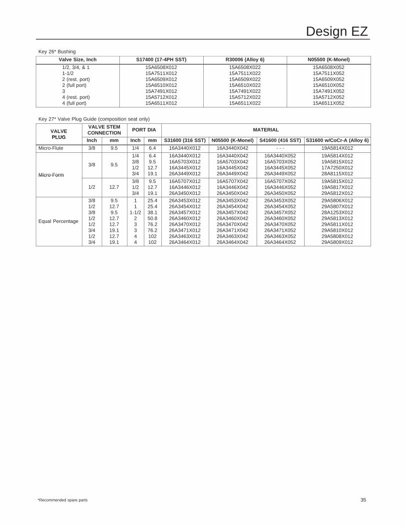
Design EZ
35
Key 26* Bushing
Valve Size, Inch S17400 (17-4PH SST) R30006 (Alloy 6) N05500 (K-Monel)
1/2, 3/4, & 11-1/22 (rest. port)2 (full port)34 (rest. port)4 (full port)
15A6508X01215A7511X01215A6509X01215A6510X01215A7491X01215A5712X01215A6511X012
15A6508X02215A7511X02215A6509X02215A6510X02215A7491X02215A5712X02215A6511X022
15A6508X05215A7511X05215A6509X05215A6510X05215A7491X05215A5712X05215A6511X052
Key 27* Valve Plug Guide (composition seat only)
VALVEPLUG
VALVE STEMCONNECTION
PORT DIA MATERIAL
PLUGInch mm Inch mm S31600 (316 SST) N05500 (K-Monel) S41600 (416 SST) S31600 w/CoCr-A (Alloy 6)
Micro-Flute 3/8 9.5 1/4 6.4 16A3440X012 16A3440X042 - - - 19A5814X012
Micro-Form
3/8 9.5
1/43/81/23/4
6.49.512.719.1
16A3440X01216A5703X01216A3445X01226A3449X012
16A3440X04216A5703X04216A3445X04226A3449X042
16A3440X05216A5703X05216A3445X05226A3449X052
19A5814X01219A5815X01217A7250X01228A8115X012Micro Form
1/2 12.73/81/23/4
9.512.719.1
16A5707X01216A3446X01226A3450X012
16A5707X04216A3446X04226A3450X042
16A5707X05216A3446X05226A3450X052
19A5815X01219A5817X01229A5812X012
Equal Percentage
3/81/23/81/21/23/41/23/4
9.512.79.512.712.719.112.719.1
11
1-1/223344
25.425.438.150.876.276.2102102
26A3453X01226A3454X01226A3457X01226A3460X01226A3470X01226A3471X01226A3463X01226A3464X012
26A3453X04226A3454X04226A3457X04226A3460X04226A3470X04226A3471X04226A3463X04226A3464X042
26A3453X05226A3454X05226A3457X05226A3460X05226A3470X05226A3471X05226A3463X05226A3464X052
29A5806X01229A5807X01228A1253X01229A5813X01229A5811X01229A5810X01229A5808X01229A5809X012
*Recommended spare parts
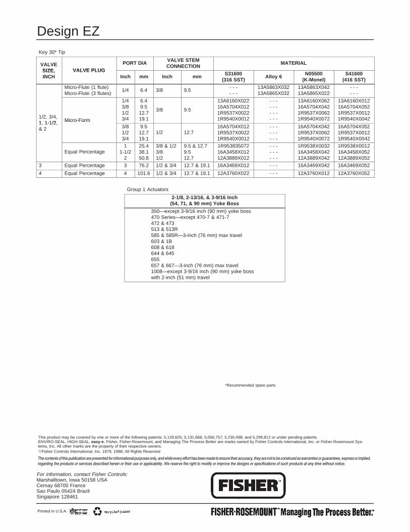
Design EZ
36
Key 30* Tip
VALVESIZE VALVE PLUG
PORT DIA VALVE STEMCONNECTION
MATERIAL
SIZE,INCH
VALVE PLUGInch mm Inch mm S31600
(316 SST)Alloy 6 N05500
(K-Monel)S41600
(416 SST)
Micro-Flute (1 flute)Micro-Flute (3 flutes)
1/4 6.4 3/8 9.5 - - -- - -
13A5863X03213A5865X032
13A5863X04213A5865X022
- - -- - -
1/2, 3/4,1 1-1/2 Micro-Form
1/43/81/23/4
6.49.512.719.1
3/8 9.5
13A6160X02216A5704X0121R9537X00221R9540X0012
- - -- - -- - -- - -
13A6160X06216A5704X0421R9537X00621R9540X0072
13A6160X01216A5704X0521R9537X00121R9540X0042
1, 1-1/2,& 2
Micro Form3/81/23/4
9.512.719.1
1/2 12.716A5704X0121R9537X00221R9540X0012
- - -- - -- - -
16A5704X0421R9537X00621R9540X0072
16A5704X0521R9537X00121R9540X0042
Equal Percentage1
1-1/22
25.438.150.8
3/8 & 1/23/81/2
9.5 & 12.79.512.7
1R95383507216A3458X01212A3889X012
- - -- - -- - -
1R9538X003216A3458X04212A3889X042
1R9538X001216A3458X05212A3889X052
3 Equal Percentage 3 76.2 1/2 & 3/4 12.7 & 19.1 16A3469X012 - - - 16A3469X042 16A3469X052
4 Equal Percentage 4 101.6 1/2 & 3/4 12.7 & 19.1 12A3760X022 - - - 12A3760X012 12A3760X052
Group 1 Actuators
2-1/8, 2-13/16, & 3-9/16 Inch(54, 71, & 90 mm) Yoke Boss
350—except 3-9/16 inch (90 mm) yoke boss470 Series—except 470-7 & 471-7472 & 473513 & 513R585 & 585R—3-inch (76 mm) max travel603 & 1B608 & 618644 & 645655657 & 667—3-inch (76 mm) max travel1008—except 3-9/16 inch (90 mm) yoke bosswith 2-inch (51 mm) travel
*Recommended spare parts
For information, contact Fisher Controls:Marshalltown, Iowa 50158 USACernay 68700 France Sao Paulo 05424 BrazilSingapore 128461
��������������� ������ ��� ���������������� ������ ������������������������� ������������������������������� ����������������������������������������������� ������������������������ ��� ��
����� ��������������������� ������� ����� ������� ������������ ��� � ��������������� ���������� ����� ����������� ���������� ��� ���������������������������� ��� ��������� ��
Printed in U.S.A.
�Fisher Controls International, Inc. 1979, 1998; All Rights Reserved
This product may be covered by one or more of the following patents: 5,129,625; 5,131,666; 5,056,757; 5,230,498; and 5,299,812 or under pending patents. ENVIRO-SEAL, HIGH-SEAL, easy-e , Fisher, Fisher-Rosemount, and Managing The Process Better are marks owned by Fisher Controls International, Inc. or Fisher-Rosemount Sys-tems, Inc. All other marks are the property of their respective owners.