Design, Development and Analysis of Hydraulic Fixture … design of fixture assembly is carried out...
7
International Research Journal of Engineering and Technology (IRJET) e-ISSN: 2395 -0056 Volume: 03 Issue: 08 | Aug-2016 www.irjet.net p-ISSN: 2395-0072 © 2016, IRJET ISO 9001:2008 Certified Journal Page 463 Design, Development and Analysis of Hydraulic Fixture for machining Engine cylinder block on VMC Abhijeet Swami 1 , Prof. G.E. Kondhalkar 2 1 PG Student, Mechanical Engineering Department, ABMSP's APCOER, SPPU, Pune 2 Professor, Mechanical Engineering Department, ABMSP's APCOER, SPPU, Pune Pune, Maharashtra, India ---------------------------------------------------------------------***--------------------------------------------------------------------- Abstract - The fixtures are work holding device used to locate and fix the position of work pieces for machining, assembly, inspection, and other operation. A fixture consists of a set of clamps and locators. Locators are used to determine the orientation and position of a workpiece, and clamps exert clamping forces on the workpiece so that the workpiece is pressed against locators and resting pads. The recent trends in industry are towards adopting the hydraulic and pneumatic techniques, because it save time generates accuracy and it is having some flexibility. Designing of hydraulically clamped fixture was considered to be lengthy and complicated procedure. Because it needs a good knowledge about, dimensioning and tolerances, manufacturing processes, clamping and cutting forces during operations. But now a day the work becomes less difficult due to introduction of intelligence in the field. By using computer aided fixture design technique the designer create a model of designed fixture and carried out finite element analysis on fixture model by considering given boundary condition before getting manufacture and can see deficiency and could make modification accordingly without getting it manufacture, which saves a great amount of money and time. In this project the same methodology is adopted for designing analyzing the designed hydraulic fixture. The hydraulic fixture is designed for Engine cylinder block to perform drilling and boring operations using Vertical machining centers. Computer aided fixture design of fixture assembly is carried out using CATIA V5 software and Finite element analysis of fixture and cylinder block is carried out using ANSYS Static workbench software. Clamping forces are calculated for 4, 5 and 6 MPa hydraulic pressure and are taken into consideration during analysis. Analysis is carried out at different tool positions to calculate the maximum stresses and deformation occurred and make modification in fixture assembly model accordingly which creates optimum fixture assembly design to get manufactured. Key Words: Hydraulic fixture, CAFD, Clamp, FEA 1. INTRODUCTION A fixture is a workpiece-locating and holding device used with machine tools. It is also used in inspection welding and assembly. The fixture is a device which sets workpiece in proper position during manufacturing operation. Frequent checking, positioning, individual marking and non-uniform quality during manufacturing process is eliminated by fixture. This increase productivity and reduce operation time. Fixture is widely used in the industry practical production because of feature and advantages. To locate and immobilize work pieces for machining, inspection, assembly and other operations fixtures are used. A fixture consists of a set of locators and clamps. Locators are used to determine the orientation and position of a workpiece, whereas clamps exert clamping forces on the workpiece so that the workpiece is pressed firmly against locators. Clamping has to be appropriately planned at the stage of machining fixture design. The design of a fixture is a highly complex and intuitive process, which require knowledge. Fixture design plays an important role at the setup planning phase. Proper fixture design is crucial for developing product quality in different terms of accuracy, surface finish and precision of the machined part. 1.1 Objectives To design, development & analysis of hydraulic fixture for machining engine cylinder block on VMC. Minimizing fixture and workpiece deflections due to clamping forces in machining for maintaining given machining accuracy and tolerances. To develop ideal fixture design that maximizes locating accuracy and workpiece stability, while minimizing displacements. By implementing FEA in a computer aided fixture design (CAFD) environment, uneconomical & unnecessary “trial and error” experimentation in the machine shop is eliminated. 2. DESIGN OF FIXTURE 2.1 Component Details The component is a Cylinder block of 4-Storke Single cylinder SI engine, made up of material Aluminum alloy AlSi 132, weighing 1.985 kg and the component to be produced by pressure die casting process. The operations to be performed on component, using designed fixture set up, are drilling and boring.
Transcript of Design, Development and Analysis of Hydraulic Fixture … design of fixture assembly is carried out...
International Research Journal of Engineering and Technology (IRJET) e-ISSN: 2395 -0056
Volume: 03 Issue: 08 | Aug-2016 www.irjet.net p-ISSN: 2395-0072
© 2016, IRJET ISO 9001:2008 Certified Journal Page 463
Design, Development and Analysis of Hydraulic Fixture for machining
Engine cylinder block on VMC
Abhijeet Swami1, Prof. G.E. Kondhalkar2
1PG Student, Mechanical Engineering Department, ABMSP's APCOER, SPPU, Pune 2Professor, Mechanical Engineering Department, ABMSP's APCOER, SPPU, Pune
Pune, Maharashtra, India
---------------------------------------------------------------------***---------------------------------------------------------------------Abstract - The fixtures are work holding device used to locate and fix the position of work pieces for machining, assembly, inspection, and other operation. A fixture consists of a set of clamps and locators. Locators are used to determine the orientation and position of a workpiece, and clamps exert clamping forces on the workpiece so that the workpiece is pressed against locators and resting pads. The recent trends in industry are towards adopting the hydraulic and pneumatic techniques, because it save time generates accuracy and it is having some flexibility. Designing of hydraulically clamped fixture was considered to be lengthy and complicated procedure. Because it needs a good knowledge about, dimensioning and tolerances, manufacturing processes, clamping and cutting forces during operations. But now a day the work becomes less difficult due to introduction of intelligence in the field. By using computer aided fixture design technique the designer create a model of designed fixture and carried out finite element analysis on fixture model by considering given boundary condition before getting manufacture and can see deficiency and could make modification accordingly without getting it manufacture, which saves a great amount of money and time. In this project the same methodology is adopted for designing analyzing the designed hydraulic fixture. The hydraulic fixture is designed for Engine cylinder block to perform drilling and boring operations using Vertical machining centers. Computer aided fixture design of fixture assembly is carried out using CATIA V5 software and Finite element analysis of fixture and cylinder block is carried out using ANSYS Static workbench software. Clamping forces are calculated for 4, 5 and 6 MPa hydraulic pressure and are taken into consideration during analysis. Analysis is carried out at different tool positions to calculate the maximum stresses and deformation occurred and make modification in fixture assembly model accordingly which creates optimum fixture assembly design to get manufactured.
Key Words: Hydraulic fixture, CAFD, Clamp, FEA
1. INTRODUCTION A fixture is a workpiece-locating and holding device used with machine tools. It is also used in inspection welding and assembly.
The fixture is a device which sets workpiece in proper position during manufacturing operation. Frequent checking, positioning, individual marking and non-uniform quality during manufacturing process is eliminated by fixture. This increase productivity and reduce operation time. Fixture is widely used in the industry practical production because of feature and advantages. To locate and immobilize work pieces for machining, inspection, assembly and other operations fixtures are used. A fixture consists of a set of locators and clamps. Locators are used to determine the orientation and position of a workpiece, whereas clamps exert clamping forces on the workpiece so that the workpiece is pressed firmly against locators. Clamping has to be appropriately planned at the stage of machining fixture design. The design of a fixture is a highly complex and intuitive process, which require knowledge. Fixture design plays an important role at the setup planning phase. Proper fixture design is crucial for developing product quality in different terms of accuracy, surface finish and precision of the machined part. 1.1 Objectives To design, development & analysis of hydraulic fixture for machining engine cylinder block on VMC. Minimizing fixture and workpiece deflections due to clamping forces in machining for maintaining given machining accuracy and tolerances. To develop ideal fixture design that maximizes locating accuracy and workpiece stability, while minimizing displacements. By implementing FEA in a computer aided fixture design (CAFD) environment, uneconomical & unnecessary “trial and error” experimentation in the machine shop is eliminated.
2. DESIGN OF FIXTURE 2.1 Component Details
The component is a Cylinder block of 4-Storke Single
cylinder SI engine, made up of material Aluminum alloy AlSi
132, weighing 1.985 kg and the component to be produced
by pressure die casting process. The operations to be
performed on component, using designed fixture set up, are
drilling and boring.

International Research Journal of Engineering and Technology (IRJET) e-ISSN: 2395 -0056
Volume: 03 Issue: 08 | Aug-2016 www.irjet.net p-ISSN: 2395-0072
© 2016, IRJET ISO 9001:2008 Certified Journal Page 464
Figure 1. shows cylinder block which is to be clamped. This
is the part to be machined and clamped in the fixture. Figure
2. shows 3D CAD model of cylinder block .Drilling and boring
operations are performed on both sides one by one that is
from top view side and bottom view side.
Fig-1: Actual cylinder block
.
Fig-2: 3D CAD model of cylinder block
2.2 Computer Aided Fixture Designs
The clamping forces applied are caused to deform the workpiece, so therefore it is important to minimize such effects by using optimal design of the hydraulic fixture layout . In machining, work holding is a main aspect, and hydraulic fixture is the element responsible to satisfy this important goal. Locating, orientating, centering, supporting, and clamping can be considered as basic functional requirements of fixtures. For this Engine cylinder block there are two types of hydraulic fixtures are designed in CATIA V5 software by considering all locating and clamping principles and from that two designs one best fixture design having less workpiece deformation and stresses is selected for development. The 1st type Fixture is having two locating pins for component location, four resting pads, and two vertical hydraulic clamps shown in Fig 3.
Fig- 3.1st type Fixture assembly with and Cylinder block
The 2nd type Fixture is having one locating pin for cylinder
block location, four resting pads, and three vertical hydraulic
clamps shown in Fig 4.
Fig-4: 2nd type Fixture assembly with Cylinder block
2.3 Clamping Forces Calculations by Analytical and
Numerical methods
The clamping forces by numerical and analytical methods
are to be calculated at given hydraulic pressure of 40, 50 &
60 bar so that from validation result we get clamping forces
values which is used in analysis of above two types of fixture
workpiece designs by using ANSYS software so that to obtain
optimized fixture workpiece design having less deformation
and less von-mises stresses.
2.3.1 Clamping Forces by Analytical Method
To calculate clamping forces by Analytical methods we
considered piston and clamp lever linkage connection in that
first we have calculated the resultant piston force acting on
clamp lever when hydraulic pressure is applied to piston
head and after that we assumed clamp lever as a rigid
element with negligible mass.

International Research Journal of Engineering and Technology (IRJET) e-ISSN: 2395 -0056
Volume: 03 Issue: 08 | Aug-2016 www.irjet.net p-ISSN: 2395-0072
© 2016, IRJET ISO 9001:2008 Certified Journal Page 465
Fig- 5: boundary conditions applied on piston
Also from above fig 5, forces acting on piston by hydraulic pressure are as follows:
1. Force acting on piston head by hydraulic pressure: F1 F1 = ( π/4) × ( Dmax)2 × ( P ) 2. Force acting on piston head by cylinder head (opposing piston force): F2 F2 = (π/4) × ( Dmean2 – Dmin2) × ( P ) 3. Net force acting on piston rod: FR FR = F1 – F2
Given Data;
Dmax = Maximum piston diameter = 32 mm ;
Dmean = Mean diameter of piston = 22 mm ;
Dmin = Minimum piston diameter = 16 mm ;
Hydraulic Pressure = P = 40, 50 & 60 bar;
P = 4,5 and 6 MPa;
So, For 4 MPa hydraulic pressure;
1. Force acting on piston head by hydraulic pressure: F1
F1 = ( π/4) × ( Dmax)2 × ( P )
F1 = (π/4) × (32)2 × 4 = 3.215 KN
2. Force acting on piston head by cylinder head (opposing
piston force): F2
F2 = (π/4) × ( Dmean2 – Dmin2) × ( P )
F2 = (π/4) × [(22)2 – (16)2] × 4 = 0.715 KN 3. Net force acting on piston rod: FR FR = F1 – F2
FR = F1 – F2 = 3.215 – 0.715 = 2.50 KN
By considering clamp lever as a rigid element with negligible mass so the forces acting on rigid beam are as follows;
Fig-6: Free Body Diagram of clamp lever
Where,
C is the point where lever is hinged.
FH is reaction force at hinge.
B is point where net piston force ( FR) applied.
A is point where clamping force ( FC ) applied.
So from Free Body Diagram;
By Newton’s first law of equilibrium;
Ʃ Vertical Force = 0
FC + FR - FH = 0;
Also, by taking moment at point C equal to zero;
ƩMC = 0 (clockwise +);
FC × 37 – FR × 21 = 0
FC = (2.5 × 21) / 37
Clamping force = FC = 1.42 KN
At hinge, Reaction Force;
FH = FC + FR = 1.42 + 2.50 = 3.92 KN
Similarly, clamping Forces for 5 and 6 MPa hydraulic
pressure are also calculated that is for 5 MPa pressure
clamping force is Fc =1.773 KN and for 6 MPa pressure
clamping force is Fc =2.130 KN respectively.
2.3.2 Clamping Forces By Numerical Method To calculate Clamping forces by Numerical Method for hydraulic pressure of 40, 50 & 60 bar using ANSYS software we consider fixture clamp design model from above CAFD. Therefore for FEA import the above piston clamp lever CAD model in ANSYS Static workbench and defines contacts between piston, small pin and clamp lever respectively.
So, for 40 bar hydraulic pressure applied on piston head in cylinder body the clamping force is calculated from FEA is as follows.
International Research Journal of Engineering and Technology (IRJET) e-ISSN: 2395 -0056
Volume: 03 Issue: 08 | Aug-2016 www.irjet.net p-ISSN: 2395-0072
© 2016, IRJET ISO 9001:2008 Certified Journal Page 466
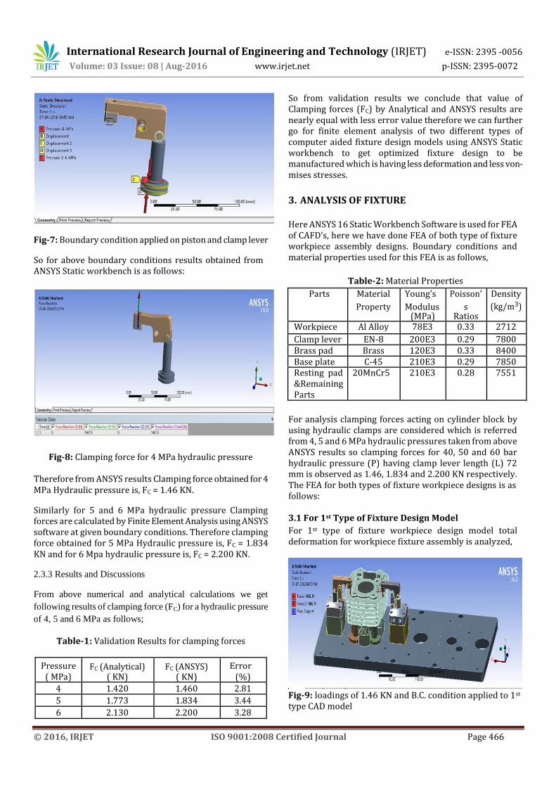
Fig-7: Boundary condition applied on piston and clamp lever
So for above boundary conditions results obtained from ANSYS Static workbench is as follows:
Fig-8: Clamping force for 4 MPa hydraulic pressure
Therefore from ANSYS results Clamping force obtained for 4 MPa Hydraulic pressure is, FC = 1.46 KN.
Similarly for 5 and 6 MPa hydraulic pressure Clamping forces are calculated by Finite Element Analysis using ANSYS software at given boundary conditions. Therefore clamping force obtained for 5 MPa Hydraulic pressure is, FC = 1.834 KN and for 6 Mpa hydraulic pressure is, FC = 2.200 KN.
2.3.3 Results and Discussions
From above numerical and analytical calculations we get
following results of clamping force (FC) for a hydraulic pressure
of 4, 5 and 6 MPa as follows;
Table-1: Validation Results for clamping forces
Pressure FC (Analytical) FC (ANSYS) Error ( MPa) ( KN) ( KN) (%)
4 1.420 1.460 2.81
5 1.773 1.834 3.44
6 2.130 2.200 3.28
So from validation results we conclude that value of Clamping forces (FC) by Analytical and ANSYS results are nearly equal with less error value therefore we can further go for finite element analysis of two different types of computer aided fixture design models using ANSYS Static workbench to get optimized fixture design to be manufactured which is having less deformation and less von-mises stresses.
3. ANALYSIS OF FIXTURE Here ANSYS 16 Static Workbench Software is used for FEA of CAFD’s, here we have done FEA of both type of fixture workpiece assembly designs. Boundary conditions and material properties used for this FEA is as follows,
Table-2: Material Properties
Parts Material Young’s Poisson’ Density Property Modulus s (kg/m3) (MPa) Ratios
Workpiece Al Alloy 78E3 0.33 2712
Clamp lever EN-8 200E3 0.29 7800 Brass pad Brass 120E3 0.33 8400 Base plate C-45 210E3 0.29 7850 Resting pad 20MnCr5 210E3 0.28 7551 &Remaining Parts
For analysis clamping forces acting on cylinder block by using hydraulic clamps are considered which is referred from 4, 5 and 6 MPa hydraulic pressures taken from above ANSYS results so clamping forces for 40, 50 and 60 bar hydraulic pressure (P) having clamp lever length (L) 72 mm is observed as 1.46, 1.834 and 2.200 KN respectively. The FEA for both types of fixture workpiece designs is as follows: 3.1 For 1st Type of Fixture Design Model
For 1st type of fixture workpiece design model total deformation for workpiece fixture assembly is analyzed,
Fig-9: loadings of 1.46 KN and B.C. condition applied to 1st type CAD model

International Research Journal of Engineering and Technology (IRJET) e-ISSN: 2395 -0056
Volume: 03 Issue: 08 | Aug-2016 www.irjet.net p-ISSN: 2395-0072
© 2016, IRJET ISO 9001:2008 Certified Journal Page 467
Fig-10: Total deformation for 1st type fixture assembly model at 1.46 KN loads
From fig 10. Maximum value of total deformation is 0.0168 mm and it is observed more near clamping area on cylinder block and also on clamp top end with brass pad. Similarly, total deformations at 1.83KN load are 0.0211mm and for 2.200KN load is 0.0253mm respectively. 3.2 For 2nd Type of Fixture Design Model For 2nd type of fixture workpiece design model total deformation for workpiece fixture assembly is analyzed,
Fig-11: loadings of 1.46 KN and B.C. condition applied to 2nd type CAD model
Fig -12: Total deformation for 2nd type fixture assembly model at 1.46 KN loads From Fig 12. Maximum value of total deformation is 0.0222
mm and it is observed more near clamping area on cylinder block and also on clamp top end with brass pad. Similarly, total deformations at 1.83KN load are 0.0279mm and for 2.200KN load is 0.0334mm respectively. 3.3 Results and Discussions
The results for total deformations from above finite element analysis of two different types of fixture design models at three different hydraulic pressure that is for different clamping forces conditions are as shown below table;
Table-3: Results for Total deformations at different Clamping Forces
Clamping Force [ Fc ] (KN)
1st type fixture model
2nd type fixture model
Total Deformations
(mm)
Total Deformations
(mm)
1.460 0.0168 0.0222
1.834 0.0211 0.0279
2.200 0.0253 0.0334
From above results of Total deformations at different clamping forces for 1st type and 2nd type fixture design the values for total deformations for 1st type fixture model at different clamp loads are less and within given tolerances limits compared to values of total deformations for 2nd type fixture model. Therefore from comparisons results we can conclude that 1st type fixture design model having two clamps is suitable for manufacturing compared to 2nd type fixture design model because due to its less deformations.
4. DEVELOPMENT AND EXPERIMENTATION OF FIXTURE 4.1 Development of Hydraulic Fixture
From above FEA results 1st type fixture design model is to be used manufacturing so the complete fixture assembly CAD model for 1st type fixture design model is as follows;
Fig-13: Final CAD model of complete fixture assembly

International Research Journal of Engineering and Technology (IRJET) e-ISSN: 2395 -0056
Volume: 03 Issue: 08 | Aug-2016 www.irjet.net p-ISSN: 2395-0072
© 2016, IRJET ISO 9001:2008 Certified Journal Page 468
Here in final CAD model of complete fixture assembly the four clamps are used which is required to decrease the machining time of drilling and boring operations because of four clamps at a time two cylinder blocks are to be machined that is one block is machined from top side and another block from bottom side due to this machining operation time is being reduced. Now, after manufacturing of all parts used in fixture and by assembling it all to develop a complete fixture assembly. The total weight of fixture is 94.54 Kg. It is manufactured and assembled according to given requirement within given tolerance limits and also required accuracy and machining allowance is maintained.
Fig-14: Manufactured fixture with cylinder block clamped
4.2 Experimentation of Manufactured Fixture For testing deformations in cylinder block at different clamping loads that is for different hydraulic pressures used for clamping a dial gauge indicator for deflection measurement is used. The results for total deformations using FEA that is by ANSYS software on cylinder block and fixture design model at different clamping loads is observed maximum near clamping positions therefore for testing total deformations on manufactured fixture the dial gauge indicator probe is placed on top surface of cylinder block near clamping areas.
Fig-15: Dial gauge indicator mounted on fixture
Least count value for dial indicator is 0.01 mm that is 10 micron. For upward movement of lever ball pointer on dial scale deflects towards clockwise direction and for downward movement of lever ball pointer deflects on anticlockwise direction. From above given experimental procedure deflection testing is carried out for hydraulic pressures of 40, 50 and 60 bar to find out deformation values at different clamping loads.
For hydraulic clamping pressure of 40 bar:
First Set dial indicator to zero without clamping, now at 40 bar
hydraulic pressure the clamping load is applied so the deflection
for this loading is as follows.
Fig-16: Deflection on cylinder block at 40 bar hydraulic
pressure
From fig 16. on cylinder block the dial test indicator shows readings slight more than 1.5 divisions which mean that the deformation value nearly equal to 16.18 micron. After testing clamps are declamped and dial pointer is set to zero. Similarly for 50 and 60 bar hydraulic pressure dial gauge indicator readings are taken at hydraulic clamping loads and deformations observed for 50 bar pressure is 22.06 microns and for 60 bar pressure is 26.12 microns respectively.
5. RESULTS AND DISCUSSIONS From FEA by using ANSYS software and Experimental testing by using Dial indicator we get following results of total deformation at different clamping loads for a hydraulic pressures of 40, 50 and 60 bars are as follows; Table-4: Validation of results for Total Deformations Hydraulic Pressure
(bar)
Clamping Force (KN)
Total Deformation (micron)
Error (%)
FEA Experimental 40 1.460 16.86 16.18 4.20
50 1.834 21.17 22.06 4.03
60 2.200 25.38 26.12 2.83

International Research Journal of Engineering and Technology (IRJET) e-ISSN: 2395 -0056
Volume: 03 Issue: 08 | Aug-2016 www.irjet.net p-ISSN: 2395-0072
© 2016, IRJET ISO 9001:2008 Certified Journal Page 469
Hence from above results of total deformation by using FEA and Experimental testing at 40, 50 and 60 bar hydraulic pressures the percentage error between FEA and Experimental results are very less and the results values are nearly equal. Therefore from above table and graph we can say that results of total deformations from finite element analysis are to be validated by experimental testing which is exactly equal. Means the manufactured fixture is accurately designed and analyzed.
6. CONCLUSIONS In this paper, the design requirements of the fixture were studied and according to that two types of CAFD had done in CATIA V5. Verification of the fixture design is carried out using ANSYS workbench. Mean while clamping forces are calculated at 40, 50 and 60 bar hydraulic pressure by using analytical and numerical methods which are validated and are taken into consideration during the static analysis of the fixture and cylinder block, so from FEA result the 1st type of fixture assembly design is to be considered for manufacturing the final fixture system. Also the FEA results of total deformations for 1st type fixture design model are validated by comparing results from experimental tests carried on fixture cylinder block, so from validation results for total deformation by FEA and Experimental tests are nearly equals. Hence we conclude that results values of total deformations and von-mises stresses from FEA are true. Means the fixture is accurately designed, analyzed and manufactured. Also for 1st type fixture design model the findings of the work can be illustrated as follows; i) CAFD greatly reduces the time for designing the fixture which is hard to design manually. ii) The use of FEA for CAFD’s environment, unnecessary and uneconomical trial and error experimentation in machine shop floor is being eliminated. iii) Also at 40 bar hydraulic pressure the cylinder block is perfectly clamped and maintained its position and stability against cutting forces, with less stress and deformation values which are below allowable limit and tolerance limit. iv) Hence for clamping 40 bar hydraulic pressure is preferred than 50 and 60 bar. v) 0.0168 mm maximum deformation is observed at 40 bar pressure which is in tolerance with machining allowance.
ACKNOWLEDGEMENT The satisfaction and exhilaration that accompany the successful completion of any task would be incomplete without the mention of the people whose constant guidance and encouragement aided in its completion.
The authors would like to express the voice of gratitude and respect to all who had directly or indirectly supported for carrying out this study and special thanks to my guide Prof.G.E.Kondhalkar, HOD, Mechanical department & Prof. K.H.Munde, ME Co-ordinator mechanical department and Prof. Dr.S.B.Thakare, Principal, Anantrao Pawar College of Engineering and Research, Parvati, Pune. I would also like to thanks Mr. Dayanand Kote (Director, Prachi Fixtures Pvt. Ltd.) and Mr. Sandeep Navghare (Design Head, Prachi Fixtures Pvt. Ltd.) who has been a source of inspiration. I am thankful to them for their support and encouragement.
REFERENCES [1] C. M. Patel, Dr.G.D.Acharya., Design and manufacturing
of 8 cylinder hydraulic fixture for boring yoke on VMC – 1050, 2nd International Conference on Innovations in Automation and Mechatronics Engineering, ICIAME 2014, pp. 405 – 412.
[2] Nicholas Amaral. Joseph J. Rencis,Yiming (Kevin) Rong, Development of a finite element analysis tool for fixture design integrity verification and optimization, International Journal Advance Manufacturing Technolnology 25, 2005, pp. 409–419.
[3] S. S. Pachbhai and L. P. Raut, Design and development of hydraulic fixture for machining hydraulic lift housing , International journal of mechanical engineering and robotics research 149, 2014, pp. Vol. 3, No. 3.
[4] Chetan M. Patel,N. P. Maniar, D. P. Vakharia, Design & manufacturing with modeling of multi component – single hydraulic fixture with 10 cylinders & expandable uniforce clamp for machining earthing terminal block on cnc - vmc 430, ASME Early Career Technical Journal 2009, Vol.8.
[5] V. S. Warule and S. M. Sawant , Design and analysis of
milling fixture for HMC, Journal of Basic and Applied Engineering Research 16, 2015, pp. 1362-1365.
[6] N.G. Lokhande and C.K. Tembhurkar, Design of angular drilling fixture and analysis of cutting forces during drilling on cylindrical surface, Journal Applied Mechanical Engineering 107, 2012, pp. 2168-9873.
[7] S.D.Ruksar, T.S. Ram Babu and M.J. Rao, Finite element analysis and optimization of machine fixture, International Journal of Current Engineering and Technology 4, 2015, pp.2156-2172.
[8] S. Selvakumar, K.P. Arulshri, K.P. Padmanaban., Clamping force optimization for minimum deformation of workpiece by dynamic analysis of workpiece-fixture system, World Applied Sciences Journal 11,2010, pp. 840-846.
[9] T.V.Harini , K.R. Sastry and Y.V. Narayana, Design and clamping force analysis of vacuum fixture to machine aerospace components, IOSR Journal of Mechanical and Civil Engineering 11,2014, pp.40-45.
[10] Komal Barge, S.M. Bhise, Design & development of hydraulic fixture for VMC, IJRASET 6, 2015, pp.174-182.