Design Criteria & Specs. for Water Mains & … · design criteria and specifications for water...
37
DESIGN CRITERIA AND SPECIFICATIONS FOR WATER MAINS AND APPURTENANCES BOARD OF PUBLIC UTILITIES CITY OF TULLAHOMA, TENNESSEE SPECIFICATIONS NO. TUB-W-287 REV. X DECEMBER 2014
Transcript of Design Criteria & Specs. for Water Mains & … · design criteria and specifications for water...
DESIGN CRITERIA AND SPECIFICATIONS
FOR
WATER MAINS AND APPURTENANCES
BOARD OF PUBLIC UTILITIES
CITY OF TULLAHOMA, TENNESSEE
SPECIFICATIONS NO. TUB-W-287 REV. X
DECEMBER 2014

FORWARD
It is intended that this design criteria and these
specifications be used for the construction of potable water
lines in the City of Tullahoma and surrounding areas
served by the Board of Public Utilities of the City of
Tullahoma, Tennessee.
i
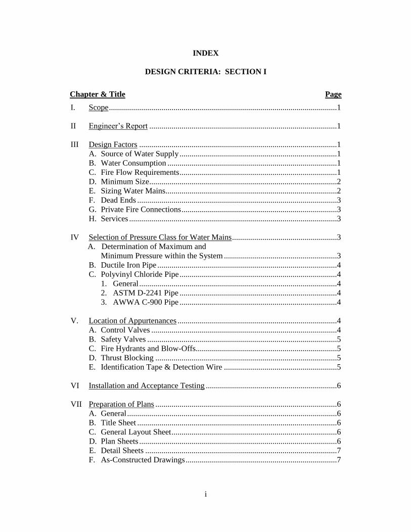
INDEX
DESIGN CRITERIA: SECTION I
Chapter & Title Page
I. Scope .................................................................................................................1
II Engineer’s Report .............................................................................................1
III Design Factors ..................................................................................................1
A. Source of Water Supply ..............................................................................1
B. Water Consumption ....................................................................................1
C. Fire Flow Requirements ..............................................................................1
D. Minimum Size .............................................................................................2
E. Sizing Water Mains.....................................................................................2
F. Dead Ends ...................................................................................................3
G. Private Fire Connections .............................................................................3
H. Services .......................................................................................................3
IV Selection of Pressure Class for Water Mains ....................................................3
A. Determination of Maximum and
Minimum Pressure within the System ........................................................3
B. Ductile Iron Pipe .........................................................................................4
C. Polyvinyl Chloride Pipe ..............................................................................4
1. General ..................................................................................................4
2. ASTM D-2241 Pipe ..............................................................................4
3. AWWA C-900 Pipe ..............................................................................4
V. Location of Appurtenances ...............................................................................4
A. Control Valves ............................................................................................4
B. Safety Valves ..............................................................................................5
C. Fire Hydrants and Blow-Offs......................................................................5
D. Thrust Blocking ..........................................................................................5
E. Identification Tape & Detection Wire ........................................................5
VI Installation and Acceptance Testing .................................................................6
VII Preparation of Plans ..........................................................................................6
A. General ........................................................................................................6
B. Title Sheet ...................................................................................................6
C. General Layout Sheet ..................................................................................6
D. Plan Sheets ..................................................................................................6
E. Detail Sheets ...............................................................................................7
F. As-Constructed Drawings ...........................................................................7

ii
CONSTRUCTION ITEMS: SECTION II
Chapter & Title Page
I. GENERAL ......................................................................................................... 8
A. Scope............................................................................................................ 8
B. Location of Mains and Appurtenances ........................................................ 8
II PRODUCTS ...................................................................................................... 9
A. Polyvinyl Chloride (PVC) Pipe ................................................................... 9
B. Ductile Iron (DI) Pipe .................................................................................. 11
C. Ductile Iron Fittings ..................................................................................... 11
D. Valves and Accessories ............................................................................... 12
1. Gate Valves .......................................................................................... 12
2. Cutting-In Sleeve and Valves .............................................................. 12
3. Tapping Sleeves and Valves ................................................................ 12
E. Valve Boxes ................................................................................................. 13
F. Fire Hydrants ............................................................................................... 13
G. Services ........................................................................................................ 14
1. Main Connections ................................................................................... 14
2. Materials for Service Connections.......................................................... 14
3. Water service Tubing .............................................................................. 14
H. Water Meters ............................................................................................... 14
I. Meter Boxes ................................................................................................. 15
J. Identification Tape and Detection Wire ...................................................... 15
III EXECUTION .................................................................................................... 16
A. Inspection of Materials ................................................................................ 16
B. Alignment and Grade ................................................................................... 16
C. Excavation of Trench ................................................................................... 16
D. Preparation of Trench Bottom ..................................................................... 18
E. Lowering Pipe and Accessories into Trench ............................................... 18
F. Installation of Pipe ....................................................................................... 18
G. Installing Pipe by Jacking and Boring Method............................................ 19
H. Installing Identification Tape ....................................................................... 19
I. Thrust Blocks .................................................................................................. 20
J. Blow-Offs on Dead End Lines........................................................................ 20
K. Setting Hydrants .......................................................................................... 20
L. Disinfection Procedures for New Water Mains ........................................... 21
M. Filling New Water Mains ............................................................................ 21
N. Testing New Water Distribution System ..................................................... 22
O. Bacteriological Tests ................................................................................... 24
P. Backfilling Trenches .................................................................................... 24
Q. Cleaning Up ................................................................................................. 24
R. Backfill and Repair of Street Cuts ............................................................... 24

iii
Chapter & Title Page
IV. STANDARD DRAWINGS ............................................................................... 25
A. Thrust Blocking Details ............................................................................... 25
B. Thrust Blocking Dimensions ....................................................................... 26
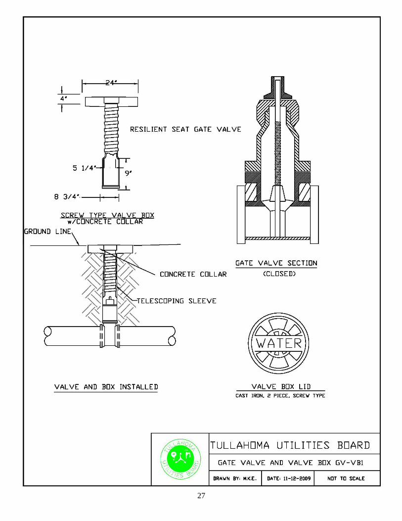
C. Gate Valve and Valve Box .......................................................................... 27
D. Fire Hydrant Assembly ................................................................................ 28
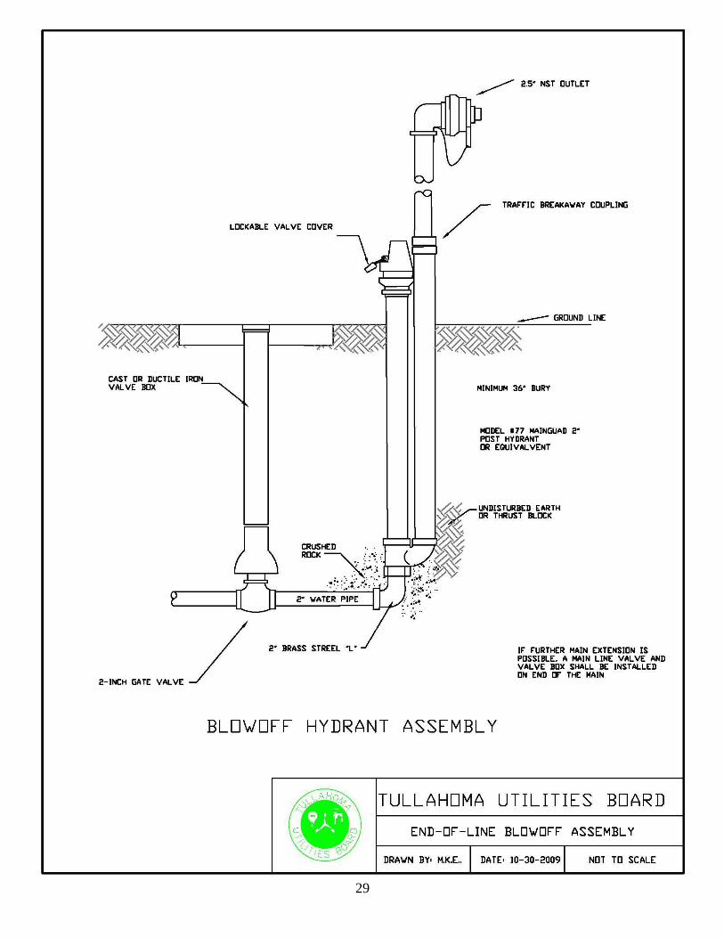
E. Blow-Off Hydrant Assembly ....................................................................... 29
F. Water Service Assembly - 5/8” x 3/4” Meter. ............................................. 30
G. Air Release Valve ........................................................................................ 31
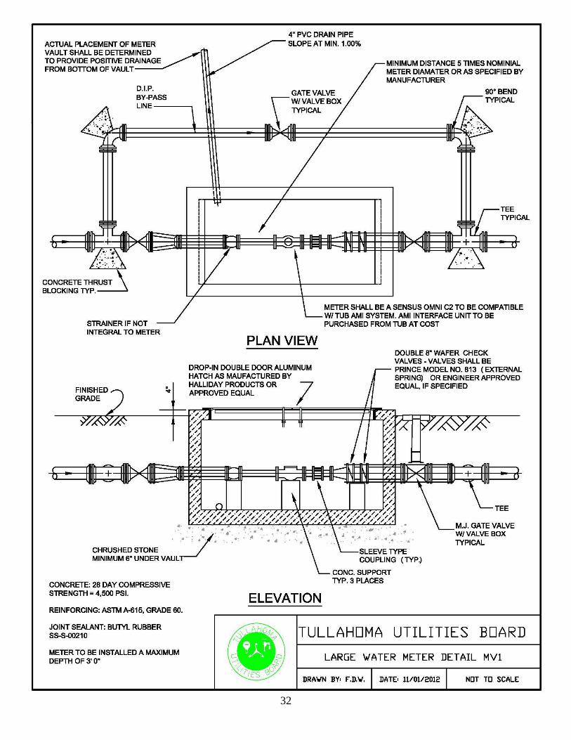
H. Large Water Meter Detail ............................................................................ 32

1
WATER DISTRIBUTION SYSTEM
DESIGN CRITERIA
SECTION I
I. SCOPE
The design criteria for water distribution systems presented hereinafter offer basic
standards for use in the design process. Much of the information contained herein, as
well as additional information may be obtained from the RULES OF TENNESSEE
DEPARTMENT OF ENVIRONMENT AND CONSERVATION, CHAPTER 0400-
45-01, PUBLIC WATER SYSTEMS, and the Division of Water Supply Community
Public Water Systems Design Criteria
II. ENGINEER’S REPORT
An engineer’s report shall be written and submitted to the Tullahoma Utilities Board
(TUB). The engineer’s report shall be submitted for review prior to the preparation of
final plans. The engineer’s report shall be submitted at least 30 days prior to the date
on which action by the TUB is desired. The engineer’s report shall address all
applicable points as set forth by these specifications.
III. DESIGN FACTORS
A. Source of Water Supply
The source of water supply for the distribution system under design shall be
thoroughly investigated to ascertain that it can supply the average and peak daily
demands imposed upon it by the proposed system without loss or burden to the
existing customers supplied by it.
B. Water Consumption
In addition to fire flow requirements, water mains and distribution systems shall
be sized for normal consumption demands of 2 gallons per minute per domestic
customer or as per Illustration I.
C. Fire flow Requirements
A minimum fire flow of 500 gallons per minute at 20 pounds per square inch
residual pressure must be available in all distribution systems containing fire
hydrants. The requirements of the Insurance Services Office and related
2
agencies shall be investigated and complied with if more stringent that the
minimum flow set forth above.
Water distribution system extensions designed to serve commercial, industrial, or
institutional users shall be evaluated and sized to provide fire protection as
required by the Insurance Services Office, and/or State and local responsible
agencies on a case-by-case basis.
D. Minimum Size
The minimum size of water distribution mains shall be that which is required to
provide the instantaneous peak demand plus fire flow while maintaining
adequate residual pressure. The minimum size of pipe allowable by TUB is 8-
inch diameter unless otherwise approved by TUB. In no case shall pipe smaller
than 6-inch diameter be allowed where fire protection is required.
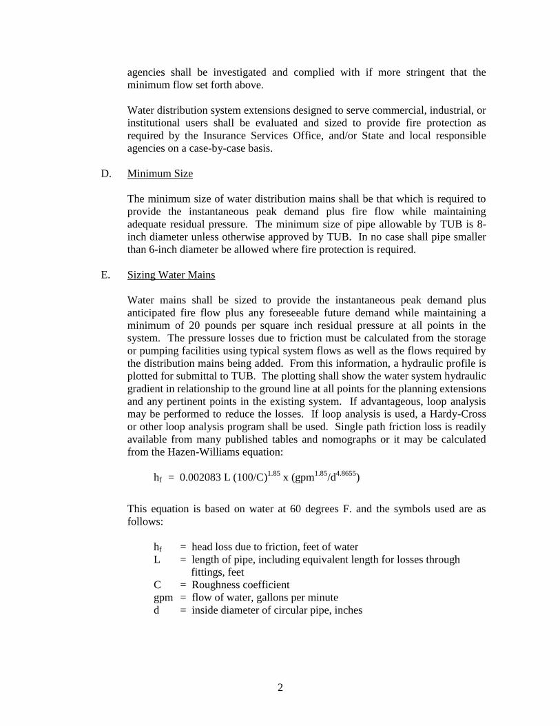
E. Sizing Water Mains
Water mains shall be sized to provide the instantaneous peak demand plus
anticipated fire flow plus any foreseeable future demand while maintaining a
minimum of 20 pounds per square inch residual pressure at all points in the
system. The pressure losses due to friction must be calculated from the storage
or pumping facilities using typical system flows as well as the flows required by
the distribution mains being added. From this information, a hydraulic profile is
plotted for submittal to TUB. The plotting shall show the water system hydraulic
gradient in relationship to the ground line at all points for the planning extensions
and any pertinent points in the existing system. If advantageous, loop analysis
may be performed to reduce the losses. If loop analysis is used, a Hardy-Cross
or other loop analysis program shall be used. Single path friction loss is readily
available from many published tables and nomographs or it may be calculated
from the Hazen-Williams equation:
hf = 0.002083 L (100/C)1.85
x (gpm1.85
/d4.8655
)
This equation is based on water at 60 degrees F. and the symbols used are as
follows:
hf = head loss due to friction, feet of water
L = length of pipe, including equivalent length for losses through
fittings, feet
C = Roughness coefficient
gpm = flow of water, gallons per minute
d = inside diameter of circular pipe, inches

3
The C value varies widely, depending on type and age of pipe. For new pipe, the
maximum value allowed by the TDEC-DWS is 130.
All calculations and the hydraulic profile shall be submitted to TUB for
consideration during their review of the plans and specifications.
F. Dead Ends
Dead end lines are detrimental to water quality and fire flows, and shall be
avoided where feasible. Loop and grid connections shall be used when possible.
Upon plans review by TUB, additional tie-ins, mains and grid connections may
be required to enhance the performance of the water system.
G. Private Fire Connections
Private fire connections shall be constructed using Ductile Iron Pipe and
appurtenances as specified in SECTION I, Chapter IV.
Where full registration metering devices are not provided, a Factory Mutual
approved water flow double check detector assembly shall be provided to
indicate water flow and ensure back flow prevention.
In all cases, backflow prevention protection equivalent to or exceeding a double
check detector assembly shall be provided.
H. Services
Each property, platted lot, or planned facility location shall be provided a water
service complete with all appurtenances, except meter, to the property line.
Services shall be installed with the distribution system.
IV. SELECTION OF PRESSURE CLASS FOR WATER MAINS
A. Determination of Maximum and Minimum Pressures Within the System
In the determination of the proper pressure class of pipe materials for use in the
system, consideration must be given to the maximum and minimum pressures
that will be encountered. The following factors must be considered when
determining pressure within a system:
1. Highest and lowest elevations of pipelines;
2. High and low levels in the water storage reservoirs;
3. Booster pumping stations - suction and discharge pressures;
4. Fire flow requirements;
4
5. Special control valves, i.e., pressure reducing valves in the system;
6. Surge allowance and water hammer; and
7. Customer water usage (present and future).
B. Ductile Iron Pipe
Ductile iron pipe is manufactured in seven (7) standard thickness classes, Class
50 through Class 56. The recommendations for thickness found in AWWA C-
151 shall be followed. It is recommended that ductile iron pipe be used when the
pipeline to be constructed is crucial to the supply of finished water to a
distribution network or in highly urbanized areas where the cost for maintenance
or replacement exceed the costs benefits realized from less expensive pipeline
materials. In addition, all private fire connections shall utilize ductile iron pipe.
C. Polyvinyl Chloride Pipe
1. General
Polyvinyl chloride (PVC) pipe for installation in water distribution systems
is manufactured under one of two standards: ASTM D-2241 or AWWA
C-900.
2. ASTM D-2241 Pipe
PVC pipe manufactured under ASTM D-2241 is pressure rated for each
Standard Dimension Ratio (SDR). The TDEC-DWS guidelines state that
ASTM D-2241 pipe shall not be used where the working pressure will
exceed 2/3 of its pressure rating. The remaining 1/3 is utilized as surge
allowance. SDR 21 may be used where the working pressure will not
exceed 133 psi and SDR 17 may be used where the working pressure will
not exceed 167 psi.
3. AWWA D-900 Pipe
AWWA C-900 PVC pipe is pressure rated for each Dimension Ratio (DR).
Due to its design, the full pressure rating can be utilized as working
pressure. DR 14 is suitable for working pressures to 200 psi and DR 18 is
suitable for working pressures to 150 psi.
V. LOCATION OF APPURTENANCES
A. Control Valves
5
Control valves (gate valves), at minimum, shall be placed at all intersections of
water mains but at no time greater than 1500 feet apart within the City limits.
Rural valves may be spaced up to 2500 feet apart.
B. Safety Valves
Safety valves (air release, pressure reducing, etc.) shall be installed at such
locations as deemed necessary for the safe, reliable operation of the distribution
system.
C. Fire Hydrants and Blow-Offs
In general, fire hydrants for residential areas shall be spaced at 600 feet or less
and/or at street intersections, whichever is less; for commercial areas, at least 400
feet or less and/or street intersections, whichever is less; and for public and
institutional properties, a number and spacing to accommodate the needed fire
flows with adequate back-up spacing. The above spacings are measured as hose
can be laid by apparatus. A fire hydrant shall be located at the end of each
extension for both fire protection and line flushing. In systems where fire
protection is not offered, blow-off hydrants shall be installed at the end of each
line and at each location required to provide adequate flushing of the mains.
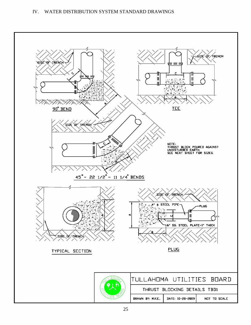
D. Thrust Blocking
Thrust forces are created in a pipeline at changes in direction, tees, dead-ends, or
where changes in pipe size occur at reducers. Acceptable restraint methods
include concrete thrust blocks, restrained joints and tie rods. The details and
dimensional data for concrete thrust blocks given in Standard Drawing TBD 1 &
2 are for 100 pounds per square inch (psi) working pressure and soil bearing load
of approximately 1000 pounds per square foot (psf). For greater pressure or less
soil bearing, the quantities required will have to be recalculated, but for pressure
less than 100 psi and soil bearing greater than 1000 psf, the thrust blocks shown
shall be adequate.
E. Identification Tape and Detection Wire
A metalized tape shall be installed in the ditch above the pipe to allow location
by a metal detecting device and to alert construction workers of the presence of a
water line. The tape shall be color coded and labeled to identify the type of line.
Tape shall be installed within one foot of finished grade and shall be at least six
inches wide.
A 14 gauge insulated copper detection wire shall be installed at the trench bottom
and stubbed up at each valve location and left accessible inside the valve box.
The wire shall form a continuing loop in the water system. All splices in the
wire shall be made securely and covered thoroughly with electrical tape.

6
VI. INSTALLATION AND ACCEPTANCE TESTING
As a minimum, the specifications shall require acceptance testing to include pressure
and leakage testing. Detailed specifications for acceptance testing are stipulated in
Section II of these specifications.
Pressure tests shall be performed at a pressure the greater of 150 psi. or 50% above the
working pressure at the test point. Pressure shall be maintained for two (2) hours. The
leakage test shall be conducted concurrently with the pressure test to check for
excessive leakage.
All water pipe shall be cleaned and disinfected in accordance with Section II of these
specifications.
VII. PREPARATION OF PLANS
A. General
Plans for water distribution mains must be submitted to TUB for review and
approval. The plans must be prepared on 24” x 36” plan sheets and the four (4)
sets submitted must be of quality suitable for reproduction. Each sheet of a set of
plans must bear a signed and dated imprint of a professional engineer’s seal.
B. Title Sheet
The title sheet for a set of plans generally contains the following: Name of
project, name of municipality, area to be served, municipal officials’ names,
index of drawings, date, address, and names of the design engineer (in addition
to seal).
C. General Layout Sheet
The general layout sheet shall include a large scale map of the entire distribution
system showing the corporate or utility district boundaries. Existing and planned
utilities shall be shown with line sizes noted and easily distinguishable between
existing and planned. The layout sheet shall incorporate both a north arrow and
scale and if the area to be served is obscure, a location plan shall be provided
showing the municipality or utility district in relation to surrounding towns,
streams, and noted landmarks.
D. Plan Sheet
The plan sheets shall be drawn at a scale of 1 inch equal to 50 feet, or other scale
approved by TUB, and be complete with north arrow, scale, street and road

7
names, existing utilities, planned utilities, and installation notes with locations
shown for all valves, hydrants, and other appurtenances. The plan sheets shall
also provide adequate descriptions of any features not otherwise covered by the
specifications. The planned water distribution mains shall have adequate notes
and stationing system to aid in the location of the water lines and appurtenances.
E. Detail Sheets
Any feature of construction which requires additional clarification to that shown
on the plan sheets shall be drawn in detail on the detail sheets. Each detail shall
cover thoroughly the dimensions, equipment, materials, method of construction,
and any clarifying notes to aid in construction of the item.
F. As-Constructed Drawings
Following the end of construction of the water distribution mains, the drawings
shall be revised to reflect any deviations from the plans and provide the precise
field location of the water mains, valves, hydrants, services, and other
appurtenances. An electronic copy compatible with TUB’s CAD system, and
one paper copy of the As-Constructed drawings shall be submitted by the
engineer to TUB while the engineer shall keep the drawings available for future
reference and additional prints, if required.
8
WATER DISTRIBUTION SYSTEM
CONSTRUCTION ITEMS
SECTION II
WATER MAINS, LATERALS, FITTINGS, VALVES, VALVE BOXES,
FIRE HYDRANTS, AND SERVICES, INCLUDING METERS
I. GENERAL
A. Scope
Work performed under this Section of the specifications shall include the
furnishing of all labor, tools, equipment, and materials; the performance of all
work necessary to install water distribution mains, laterals, fittings, valves, fire
hydrants, and appurtenances; and the installation of pipe by the jacking and
boring method, all complete and ready for use.
Work performed under this Section of the specifications shall conform to the
applicable requirements of “American National/AWWA Standard for Installation
of Ductile-Iron Water Mains and Appurtenances”, ANSI/AWWA C600 of latest
revision, unless specifically modified by these specifications.
B. Location of Mains and Appurtenances
1. The general location of water mains, laterals, and appurtenances is
indicated on the plans of the various streets.
2. Where the locations of water mains, laterals, and appurtenances are shown
on the plans referred to street center-line or base lines, these locations shall
be rigidly adhered to.
3. Valves on water distribution shall be located within the street right-of-way
unless detailed location is shown otherwise on the plans.
4. Fire hydrants shall be set at locations shown on the plans or as directed by
TUB. Fire hydrants shall be set in such a position that all nozzles and
operating nuts are fully accessible and have adequate clearance from any
obstacle. Locations shall be chosen which will provide protection from
damage from vehicular traffic and interfere as little as possible with
pedestrian traffic.
9
II. PRODUCTS
A. Polyvinyl Chloride (PVC) Pipe
1. All plastic pressure pipe shall be made from Class 12454-B polyvinyl
plastic PVC 1120) as defined by ASTM D1784.
2. All PVC pipe shall be Class 200 (SDR 21), Class 250 (SDR 17), or Class
315 (SDR 13.5) pipe, as indicated on the drawings. All PVC pipe shall
have NSF approval and be manufactured in accordance with ASTM
D2241, except that the following tests shall be run at least once each hour
per machine on each size and type of pipe being produced.
a. Flattening Test: A specimen at least 2” long shall be flattened
between moving parallel plats in a suitable press until the opposite
inside surface touch and 100% flattening has occurred. The rate of
loading shall be uniform and such that the compression (100%
flattening) is complete within 2 to 3 minutes. Upon completion of
the test, the specimen shall not be split, cracked, or broken.
b. Extrusion Quality Test: The method of testing shall be in accordance
with ASTM D2152. There shall be no flaking, peeling, cracking, or
visible deterioration on the inside or outside surface after completion
of the tests.
c. Quick Burst Test: This test shall be performed in accordance with
ASTM D1599. The PVC pipe specimen shall be pressurized to burst
between 60 and 70 seconds. The burst pressure must exceed the
minimum burst pressure requirements given below:
Minimum Bursting
SDR Pressure Rating Pressure, psi
13.5 315 1,200
17 250 1,000
21 200 800
d. Impact Test: All SDR 13.5 to 21 (315 to 200 pound pressure rated)
pipe shall be tested. The manufacturer shall also provide results of
impact tests conducted.
3. If any specimen fails to meet any of the above mentioned tests, all pipe of
that size and type manufactured between the test periods must be scrapped.
4. The pipe manufacturer shall furnish a certificate stating that he is fully
competent to manufacture PVC pipe of uniform texture and strength and in
10
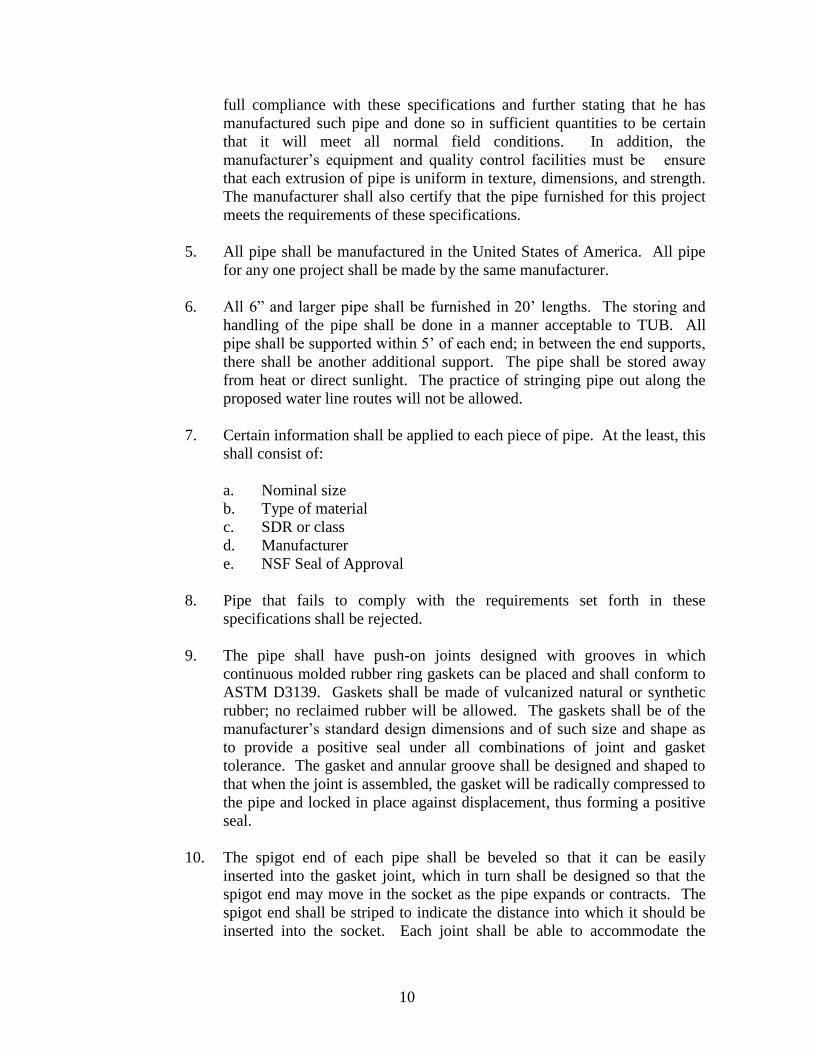
full compliance with these specifications and further stating that he has
manufactured such pipe and done so in sufficient quantities to be certain
that it will meet all normal field conditions. In addition, the
manufacturer’s equipment and quality control facilities must be ensure
that each extrusion of pipe is uniform in texture, dimensions, and strength.
The manufacturer shall also certify that the pipe furnished for this project
meets the requirements of these specifications.
5. All pipe shall be manufactured in the United States of America. All pipe
for any one project shall be made by the same manufacturer.
6. All 6” and larger pipe shall be furnished in 20’ lengths. The storing and
handling of the pipe shall be done in a manner acceptable to TUB. All
pipe shall be supported within 5’ of each end; in between the end supports,
there shall be another additional support. The pipe shall be stored away
from heat or direct sunlight. The practice of stringing pipe out along the
proposed water line routes will not be allowed.
7. Certain information shall be applied to each piece of pipe. At the least, this
shall consist of:
a. Nominal size
b. Type of material
c. SDR or class
d. Manufacturer
e. NSF Seal of Approval
8. Pipe that fails to comply with the requirements set forth in these
specifications shall be rejected.
9. The pipe shall have push-on joints designed with grooves in which
continuous molded rubber ring gaskets can be placed and shall conform to
ASTM D3139. Gaskets shall be made of vulcanized natural or synthetic
rubber; no reclaimed rubber will be allowed. The gaskets shall be of the
manufacturer’s standard design dimensions and of such size and shape as
to provide a positive seal under all combinations of joint and gasket
tolerance. The gasket and annular groove shall be designed and shaped to
that when the joint is assembled, the gasket will be radically compressed to
the pipe and locked in place against displacement, thus forming a positive
seal.
10. The spigot end of each pipe shall be beveled so that it can be easily
inserted into the gasket joint, which in turn shall be designed so that the
spigot end may move in the socket as the pipe expands or contracts. The
spigot end shall be striped to indicate the distance into which it should be
inserted into the socket. Each joint shall be able to accommodate the

11
thermal expansions and contractions experienced with a temperature shift
of at least 75 degrees F.
11. Enough lubricant shall be furnished with each order to provide a coat on
the spigot end of each pipe. This lubricant shall be non-toxic, impart no
taste or smell to the water, have no harmful effect on the gasket or pipe
material, and support no bacterial growth. The lubricant containers shall
be labeled with the manufacturer’s name.
12. Joints shall be either integral bell and ring joints with rubber compression
gaskets as manufactured by the Clow Corporation, twin gasket couplings
as manufactured by the Certain-Teed-Products Corporation, gaskets as
manufactured by John-Manville, or equal. However, the pipe and bell
must be made by the same manufacturer.
B. Ductile Iron (DI) Pipe
1. All DI pressure pipe will be manufactured in accordance with ANSI A-
21.50 (AWWA C-151) and ANSI A-21.10 (AWWA C-100).
2. All DI pipe shall have a standard cement lining meeting the requirements
of ANSI 21.4 (AWWA C-104).
3. A minimum of 1 mil thick bituminous coating shall be on the outside
surface of all DI pipe.
4. Pipe shall be clearly marked with manufacturer’s name, D.I. or ductile,
weight, class or nominal thickness, and casting period.
5. Unless otherwise specified or shown on the plans, DI pipe shall be
thickness Class 52.
6. Joints shall be either push-on or mechanical joint configuration.
C. Ductile Iron Fittings
1. Fittings: Ductile iron fittings shall conform to the requirements of the
American Standard Specifications, ANSI A21.10/AWWA C110, Ductile-
iron and Gray-iron Fittings, 3-inch through 48-inch for Water and Other
Liquids, latest revision. Standard mechanical joint fittings shall be used.
The gaskets shall be the proper kind for attachment with the type of pipe
being used.
2. Coatings and Linings: All ductile iron fittings shall be given an outside
bituminous coating, as stipulated in the ANSI specifications referred to
above. Fittings shall be lined with Enameline or a thin cement lining in

12
accordance with American National Standard ANSI A21.4/AWWA C104,
latest revision. In addition, a bituminous seal coat or asphalt emulsion
spray coat approximately 1 mil thick shall be applied to the cement lining
accordance with the pipe manufacturer’s standard practices.
D. Valves and Accessories
1. Resilient Seat Gate Valves:
a. Resilient seat gate valves shall have a full opening equal to the size
of the pipe on which they are installed and shall open by turning
counterclockwise.
b. Resilient seat gate valves shall be iron body, machined surface,
modified wedge disc, resilient rubber seat type valves. Resilient seat
gate valves shall have the bronze stem nut cast integrally with the
cast iron valve disc. The valve shall have machined seating surface
and capable of being installed and operated in either direction.
Valves shall be furnished with mechanical joint ends in accordance
with USA Standard A21.11 unless otherwise shown or directed.
c. All valves installed below ground shall be non-rising stem type with
two-inch square operating nut, marked to indicate the direction of
opening. All underground valves which have nuts deeper than 30
inches below the valve box top shall have extended stems with nuts
located within one foot of the valve box cap. All valves installed
above ground shall be outside stem and yoke (OS&Y) type equipped
with hand wheel for manual operation, marked to indicate the
direction of opening.
d. Valves shall be for working pressure up to 200 psi and shall be equal
to latest specifications of AWWA C509 in all respects.
e. Valves shall be suitable for installation in the vertical position in
buried pipe lines. Stem shall consist of O-ring seals. Valves shall be
manufactured by Mueller or equal.
2. Cutting-In Sleeve and Valves:
Cutting-In sleeve shall be Mueller H-840, M & H or approved equal, and
the gate valves shall be Mueller H-862, M & H, or approved equal.
3. Tapping Sleeve and Valves:
13
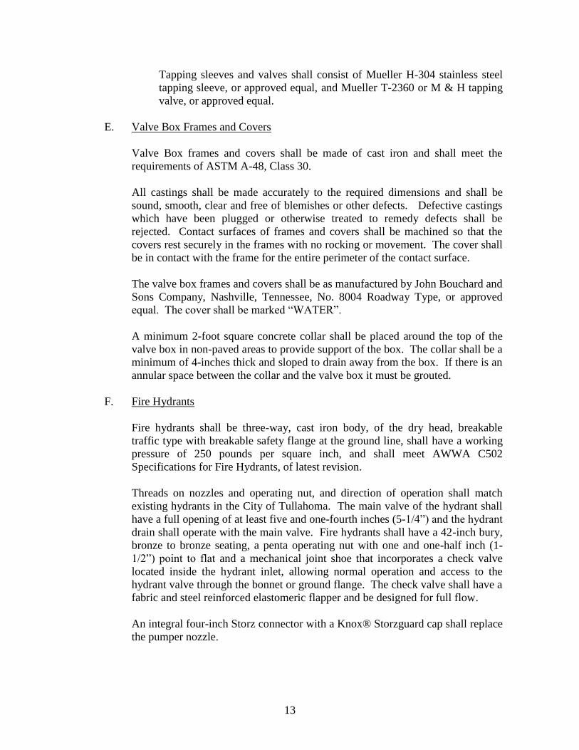
Tapping sleeves and valves shall consist of Mueller H-304 stainless steel
tapping sleeve, or approved equal, and Mueller T-2360 or M & H tapping
valve, or approved equal.
E. Valve Box Frames and Covers
Valve Box frames and covers shall be made of cast iron and shall meet the
requirements of ASTM A-48, Class 30.
All castings shall be made accurately to the required dimensions and shall be
sound, smooth, clear and free of blemishes or other defects. Defective castings
which have been plugged or otherwise treated to remedy defects shall be
rejected. Contact surfaces of frames and covers shall be machined so that the
covers rest securely in the frames with no rocking or movement. The cover shall
be in contact with the frame for the entire perimeter of the contact surface.
The valve box frames and covers shall be as manufactured by John Bouchard and
Sons Company, Nashville, Tennessee, No. 8004 Roadway Type, or approved
equal. The cover shall be marked “WATER”.
A minimum 2-foot square concrete collar shall be placed around the top of the
valve box in non-paved areas to provide support of the box. The collar shall be a
minimum of 4-inches thick and sloped to drain away from the box. If there is an
annular space between the collar and the valve box it must be grouted.
F. Fire Hydrants
Fire hydrants shall be three-way, cast iron body, of the dry head, breakable
traffic type with breakable safety flange at the ground line, shall have a working
pressure of 250 pounds per square inch, and shall meet AWWA C502
Specifications for Fire Hydrants, of latest revision.
Threads on nozzles and operating nut, and direction of operation shall match
existing hydrants in the City of Tullahoma. The main valve of the hydrant shall
have a full opening of at least five and one-fourth inches (5-1/4”) and the hydrant
drain shall operate with the main valve. Fire hydrants shall have a 42-inch bury,
bronze to bronze seating, a penta operating nut with one and one-half inch (1-
1/2”) point to flat and a mechanical joint shoe that incorporates a check valve
located inside the hydrant inlet, allowing normal operation and access to the
hydrant valve through the bonnet or ground flange. The check valve shall have a
fabric and steel reinforced elastomeric flapper and be designed for full flow.
An integral four-inch Storz connector with a Knox® Storzguard cap shall replace
the pumper nozzle.

14
Fire hydrants shall be Mueller® Super Centurion 250/HS High Security Model
A-423.
G. Services
1. Main Connections: All tapping of mains shall be done in the upper half of
the pipe and approximately at a 45 angle from the vertical. Tapping
saddles shall be used for all taps on PVC pipe.
2. Materials for Service Connections: All corporation cocks, fittings, and
curb cocks shall be made of brass. The following items shall be as
hereinafter described:
a. Corporation stop with Mueller thread inlet and compression outlet --
Ford, Mueller, or equal.
b. Tapping saddles, bronze.
c. Meter yoke, 5/8” x 3/4” - Ford 70 Series Coppersetter VB72-7W-41-
33 or approved equal.
d. Meter yoke, 1” – Ford 70 Series Coppersetter VB74-10W-41-44 or
approved equal.
e. Meter yoke, 2” – with bypass, Ford Coppersetter VBB77-15B-11-77
or approved equal.
3. Crosslinked Polyethylene (PEX) Water Service Tubing: Service line
tubing shall be Rehau Municipex® crosslinked polyethylene (PEX) tubing,
or approved equal. The tubing must meet or exceed the requirements of
ASTM F876, F877, CSA B137.5 and PPI TR-3, and be certified to NSF
Standards 14/61 and AWWA C904. The tubing shall meet the
requirements of ASTM F2023 for chlorine resistance.
The tubing shall be produced in SDR 9 copper tube sizes allowing it to
connect to standard compression-joint brass valves and fittings using
inserts (required) per the recommendation of the fitting manufacturer.
H. Water Meters
1. All water meters of sizes 5/8”x3/4”, 3/4”, and 1” shall conform to the
following specifications:
a. General: All meters shall conform to AWWA C700, Standard for
Cold-Water Meters -- Displacement Type, of latest revision. All water
meters of this size shall be manufactured by Hersey and be compatible
with the Mueller Mi.Net AMI system.

15
b. Registers: The registers shall be of the double or hermetically sealed,
direct reading type registering in gallons and shall be equipped with a
center sweep hand. The engineer is to coordinate the type of
registration with TUB if meters are to be supplied with development.
c. Capacity, Accuracy, and Test Certification: Capacity, accuracy, and
test certification shall comply with AWWA C700.
d. Guarantee: Each meter shall be guaranteed for a period of one year
from date of installation as per section 21 of AWWA C700. Registers
shall be guaranteed for a period of ten years.
e. Connections: The 5/8” meter will have 3/4” meter yokes and shall be
referred to as 5/8” x 3/4” meters.
2. All water meters of sizes 1-1/2”, 2”, 3”, 4” and 6” shall conform to the
following specifications: a.General: All meter packages shall meet or exceed requirements of
ANSI/AWWA Standard C702 for class II compound meter assemblies. All
meters of this size shall be Sensus OMNI™ C2.
Electronic Registers: The meter’s register shall be all-electronic and contain
no mechanical gearing. The electronic register shall include the following
partial list of features: AMR resolutions units fully programmable, Pulse
output frequency fully programmable, Integral data logging capability,
Integral resettable accuracy testing feature, LCD display, and 10 year battery
life.
I. Meter Boxes: Meter boxes shall be high-density polyethylene of one-piece molded
construction and shall have a wall thickness of no less than 0.550 inches. The meter box,
with a ductile iron cover installed shall be able to bear a 20,000 lb load in a wheel load (H-
20) style test, and able to withstand a 200 lb side load. The exterior of the meter box shall be
black to prevent UV degradation, and bright white on the interior to reflect light and ease
meter reading and service. The box shall be designed in such a way as to have an integral
flange, no more than 3 inches from the top, to support the box in concrete, paving and soil,
and bottom flange a minimum of 1 inch wide to help retard settling. The box shall have
removable pre-cut entry areas, 3” wide x 4” high, located on the center of each end of the
box. The box shall be designed in such a way as to be securely stackable, and shall be
available in 18 inch heights. The meter box shall be model MSBCF-XL as manufactured by
Mid-States Plastics Inc. or approved equal.
J. Identification Tape and Detection Wire The identification tape shall be metalized to allow location by a metal detecting
device. The tape shall be color coded and labeled to identify the line as a water
line. Tape shall be at least six inches wide and shall be as manufactured by
16
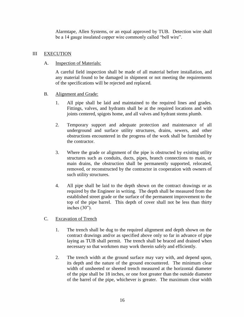
Alarmtape, Allen Systems, or an equal approved by TUB. Detection wire shall
be a 14 gauge insulated copper wire commonly called “bell wire”.
III EXECUTION
A. Inspection of Materials: A careful field inspection shall be made of all material before installation, and
any material found to be damaged in shipment or not meeting the requirements
of the specifications will be rejected and replaced.
B. Alignment and Grade:
1. All pipe shall be laid and maintained to the required lines and grades.
Fittings, valves, and hydrants shall be at the required locations and with
joints centered, spigots home, and all valves and hydrant stems plumb.
2. Temporary support and adequate protection and maintenance of all
underground and surface utility structures, drains, sewers, and other
obstructions encountered in the progress of the work shall be furnished by
the contractor.
3. Where the grade or alignment of the pipe is obstructed by existing utility
structures such as conduits, ducts, pipes, branch connections to main, or
main drains, the obstruction shall be permanently supported, relocated,
removed, or reconstructed by the contractor in cooperation with owners of
such utility structures.
4. All pipe shall be laid to the depth shown on the contract drawings or as
required by the Engineer in writing. The depth shall be measured from the
established street grade or the surface of the permanent improvement to the
top of the pipe barrel. This depth of cover shall not be less than thirty
inches (30”).
C. Excavation of Trench
1. The trench shall be dug to the required alignment and depth shown on the
contract drawings and/or as specified above only so far in advance of pipe
laying as TUB shall permit. The trench shall be braced and drained when
necessary so that workmen may work therein safely and efficiently.
2. The trench width at the ground surface may vary with, and depend upon,
its depth and the nature of the ground encountered. The minimum clear
width of unsheeted or sheeted trench measured at the horizontal diameter
of the pipe shall be 18 inches, or one foot greater than the outside diameter
of the barrel of the pipe, whichever is greater. The maximum clear width

17
of trench at the top of the pipe shall be not more than the outside diameter
of the barrel of the pipe plus two feet.
3. The pipe shall be laid on firm soil, cut true and even to afford bearing for
the full length of the barrel of the pipe, or on earth mounds.
4. Any part of the trench excavated below grade shall be corrected with
thoroughly compacted material approved by TUB.
5. When an unstable sub-grade condition is encountered, an additional depth
shall be excavated and refilled to pipe foundation grade with crushed stone
or other suitable material as required to achieve a satisfactory trench
bottom.
6. Ledge rock, boulders, and large stones shall be removed to provide
clearance to each side of, and below, all pipe and accessories. This
clearance for pipe and accessories shall be six inches.
7. Excavations below sub-grade in rock or in boulders shall be refilled to sub-
grade with material approved and thoroughly compacted.
8. Wherever necessary to prevent craving, trench excavations in soils such as
sand, gravel, and sandy soil shall be adequately sheeted and braced. Where
sheeting and bracing are used, the trench width shall not be less than that
specified above. As backfill is placed, if sheeting is to be withdrawn, it
shall be withdrawn in increments not to exceed one foot, and the void left
by the withdraw sheeting shall be filled and compacted.
9. All excavated materials shall be piled in a manner that will not endanger
the work and will avoid obstructing sidewalks and driveways. Gutters
shall be kept clear or other satisfactory provisions made for street drainage.
10. The use of trench-digging machinery will be permitted except where its
operations will cause damage to trees, buildings, or existing structures
above or below the ground. At such locations, methods by hand shall be
employed to avoid such damage.
11. To protect persons from injury and to avoid property damage, adequate
barricades, construction signs, torches, warning lights and guards as
required shall be placed and maintained during the progress of the
construction work and until it is safe for traffic use. Whenever required,
watchmen shall be provided to prevent accidents. Rules and regulations of
the local authorities regarding safety provisions shall be observed.
12. Excavations for pipe laying operations shall be conducted to cause the least
interruption to traffic: Hydrants under pressure, valve-pit covers, valve

18
boxes, curb-stop boxes, fire or police call boxes, or other utility controls
shall be unobstructed and accessible during the construction period.
13. Adequate provisions shall be made for the flow in sewers, drains, and
water courses encountered during construction. The structures which may
have been disturbed shall be satisfactorily restored.
D. Preparation of Trench Bottom:
1. Pipe shall be laid directly on a trench bottom containing coupling holes so
as to provide a continuous contact with the pipe between coupling holes.
2. Coupling Holes: Prior to lowering pipe into the trench, a coupling hole
shall be dug in the trench bottom having a length, width, and depth to
allow assembly and to maintain a minimum clearance of two inches (2”)
between coupling and undisturbed trench bottom.
3. Shaping Trench Bottom: Prior to lowering pipe into the trench, the trench
bottom between coupling holes shall be made flat and cut true and even to
grade so as to provide continuous contact of the trench bottom with the
pipe.
E. Lowering Pipe and Accessories into Trench:
1. All pipe, fittings, valves, hydrants, and accessories shall be carefully
lowered into the trench using suitable equipment in such a manner as to
prevent damage to pipe and fittings. Under no circumstances shall pipe or
accessories be dropped or dumped into the trench.
2. The pipe and accessories shall be inspected for defects prior to lowering
into trench. Any defective, damaged, or unsound material shall be repaired
or replaced.
3. All foreign matter or dirt shall be removed from the interior of pipe before
lowering into position in the trench. Pipe shall be kept clean.
F. Installation of Pipe:
1. The interiors of pipes, fittings and valves shall be protected from
contamination. The pipe delivered for construction shall be strung so as to
minimize the entrance of foreign material. If dirt enters the pipe, it shall be
removed and the interior pipe surface swabbed with a 1 or 5 percent
hypochlorite solution. The new water main must be isolated from the
active water distribution system until bacteriological tests are satisfactorily
completed.

19
2. After a length of pipe has been placed in the trench with the spigot end
forced home in the bell of the adjacent pipe, it shall be brought to the
correct line and grade, and secured in place by tamping an approved
backfill material around it.
3. Whenever pipe-laying is not in progress, the open ends of pipe shall be
closed either with a watertight plug or by other approved means. If there is
water in a trench, this seal shall be left in place until the trench has been
pumped completely dry.
4. The pipe shall be cut so that valves, fittings, or closure pieces can be
inserted in a neat and workmanlike manner and without any damage to the
pipe. The manufacturer’s recommendation shall be followed concerning
how to cut and machine the ends of the pipe in order to leave a smooth end
at right angles to the pipe’s axis.
5. Properly restrained bends shall be used for all major alignment changes.
Joint deflections shall only be used for minor alignment changes necessary
to avoid obstructions. Long radius curves by joint deflection shall only be
used if approved by the TUB. In any event, joint deflectors shall not
exceed manufacturer’s recommendations, or that necessary for the joint to
be satisfactorily made.
6. No pipe shall be laid in water or when trench conditions are unsuitable. If
crushed stone is used to improve trench conditions or as backfill for
bedding the pipe, its use is considered incidental to the project, and no
separate payment will be made for its use.
7. Where a water line crosses over a sanitary sewer, a full length of pipe shall
be used with its joints straddling the sewer. Where a water line is to be
parallel to a sanitary or storm sewer, it shall be laid at least 10’ from the
sewer. If it is not practical for the water and sewer lines to be separated as
described above, the water line shall be laid at least 18” above the top of
the sewer.
8. All pipe shall be joined in the exact manner specified by the manufacturer
of the pipe and jointing materials.
G. Installing Pipe by Jacking and Boring Method:
Where water mains and laterals (except service lines) are to be installed in paved
streets, roadways, sidewalks, etc., and it is undesirable to install pipe under this
surface by means of an open cut trench, the contractor will install this pipe by
jacking and boring.
H. Installing Identification Tape and Detection Wire:

20
A metalized identification tape shall be installed over the pipe and within one
foot of finished grade.
A detection wire shall be installed with the pipe at the trench bottom. Wire shall
be stubbed up at each valve location and left accessible inside the valve box.
The wire shall form a continuous loop in the water system.
I. Thrust Blocks:
All reducers, caps, tees, eighth bends or greater, and such parts of the pipe work
that will have a tendency to draw away or separate, shall be secured firmly by
concrete thrust blocks poured as detailed on the plans or as directed by TUB.
J. Blow-Offs on Dead End Lines:
The contractor shall install a two-inch (2”) blow-off on the end of each dead end
line, except where fire hydrants are installed, to facilitate filling, sterilizing, and
blowing-off of lines, both during construction and system operation.
K. Setting Hydrants:
1. Hydrants shall be lowered into the trench, inspected, cleaned and
connected to pipe, and reaction or thrust blocks provided as specified
herein for installation of water mains, laterals and fittings.
2. Each hydrant shall be connected to the main with a six-inch (6”) pipe
branch controlled by an independent six-inch (6”) gate valve. Lengths of
pipe and use of couplings between main and valve and hydrant shall be as
shown on the drawings.
3. Whenever hydrants are set in soil classified as impervious, a drainage pit
two feet in diameter and two feet deep shall be excavated below each
hydrant. The pit shall be filled compactly with course gravel or broken
stone mixed with course sand, under and around the bowl of the hydrant to
a level six inches (6”) above the waste opening. No hydrant drainage pit
shall be connected to a sewer.
4. A reaction or thrust backing shall be provided at the bowl of each hydrant
and shall be so placed as not to obstruct the drainage outlet of the hydrant,
or the bowl of the hydrant shall be tied to the pipe main with rods.
5. Hydrants shall be thoroughly cleaned of dirt or other foreign matter before
setting.
6. Hydrants shall be painted after installation with industrial quality paint.
The barrel of the hydrant will be recoated with yellow paint and the bonnet
color will be coated with a color specified by TUB.

21
L. Disinfection Procedures for New Water Mains
Calcium hypochlorite (HTH) granules that have been certified by the National
Sanitation Foundation shall be used to disinfect newly installed water lines. The
HTH granules shall be placed at the upstream end of the first section of pipe, at
the upstream end of each branch main, at fire hydrant laterals and at 500 feet
intervals of the new water system. The information in the table shown below
lists the proper quantity of HTH for varying sizes of water mains.
Amount of Calcium
Pipe Diameter (in.) Hypochlorite Granules (oz.)
4 1.7
6 3.8
8 6.7
12 10.5
14 and larger D2 x 15.1
(D is the inside diameter in feet)
TUB’s water disinfection procedures that have been approved by TDEC DWS
shall be used in cases in which water lines have been cut into whether by
accident or design. TUB shall be made aware of any incidence of this type. The
proper paperwork to record the disinfection procedures used shall be completed
and filed by TUB.
M. Filling New Water Mains:
1. When the installation has been completed, the new water mains shall be
filled so that the water in the mains has a velocity no greater than 1.0 ft/sec.
The valves shall be manipulated so the highly chlorinated water will not
flow back into the line that is supplying the water. Only TUB employees
are allowed to operate the valves used to fill the new mains.
2. All air pockets must be eliminated. If fire hydrants or blow-off hydrants
are not available at high points in the mains, the pipe shall be tapped at
high points to vent the air.
3. The chlorinated water shall be retained in the lines for at least 24 hours,
during which time all valves and hydrants in the line being treated shall be
operated so that appurtenances can also be disinfected. After 24 hours, the
treated water shall have a detectable free chlorine residual throughout the
system.
4. After the applicable retention period, heavily chlorinated water should not
remain in prolonged contact with the pipe. If there is high chlorine
residual in the water, the water mains and laterals shall be flushed until the

22
chlorine residual level in the new lines is no higher than the level normally
found in the water distribution system.
N. Testing Water Distribution System:
1. The contractor shall provide all necessary equipment, gauges, labor tools,
and services, and shall perform all work required in connection with testing
water mains, laterals, and service lines. An representative of TUB must be
present to witness the tests.
2. The contractor shall perform all pressure and leakage tests before
backfilling the trenches.
a. Pressure Test:
i. Before TUB shall accept any water lines, these lines or each
valved section shall be tested at a hydrostatic pressure of at
least 150 pounds per square inch. In low areas of the system
where the working pressure plus 50 percent (50%) of this
working pressure exceed 150 pounds per square inch, the lines
(in the low areas) shall be tested at the working pressure plus
50 percent (50%) of this working pressure.
ii. The duration of each pressure test shall be at least one hour.
iii. The specified test pressure (based on the elevation of the
lowest point of the line or section under test and corrected to
the elevation of the test gauge) shall be applied with a pump
connected to the pipe.
iv. All exposed pipes, fittings, valves, and hydrants shall be
carefully examined during the test. Any cracked or defective
pipes, fittings, valves, or hydrants discovered in consequences
of this pressure test shall be removed and replaced with sound
material in the manner specified. Repeat the test until the
results are satisfactory.
b. Leakage Test:
i. The leakage test shall be conducted after the pressure test has
been satisfactorily completed.
ii. The duration of each leakage test shall be 2 hours.
iii. During the test, the main shall be subjected to a pressure of 150
pounds per square inch.

23
iv. Leakage is defined as the amount of water which must be
supplied to the newly laid pipe or any valved section in order
to maintain the specified leakage test pressure after the pipe
has been filled with water and the air expelled.
v. No pipe installation will be accepted until the leakage per 2-
hour period is less than the number of gallons listed below:
Gallons per 1,000 Feet
Pipe Sizes of Pipe .
2-1/4” and smaller 0.2
3” 0.5
4” 0.6
6” 0.9
8” 1.2
10” 1.5
12” 1.9
14” 2.2
16” 2.6
18” 2.9
20” 3.2
24” 3.8
vi. For pressures exceeding the minimum of 150 pounds per
square inch during the test period, the allowable leakage shall
be based upon the following formula:
L = ND P Where L = allowable leakage in gallons per
7400 hour
N = number of joints in length of pipe
line tested
D = nominal diameter of pipe in inches
P = average test pressure during the
leakage test in pounds per square
inch.
vii. Should any test of pipe laid disclose leakage greater than that
specified, the defective joints shall be located and repaired
until the leakage is within the specified allowance.
24
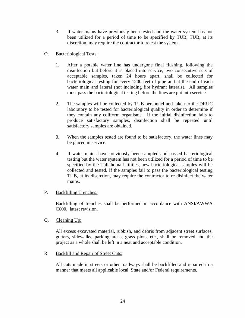
3. If water mains have previously been tested and the water system has not
been utilized for a period of time to be specified by TUB, TUB, at its
discretion, may require the contractor to retest the system.
O. Bacteriological Tests:
1. After a potable water line has undergone final flushing, following the
disinfection but before it is placed into service, two consecutive sets of
acceptable samples, taken 24 hours apart, shall be collected for
bacteriological testing for every 1200 feet of pipe and at the end of each
water main and lateral (not including fire hydrant laterals). All samples
must pass the bacteriological testing before the lines are put into service
2. The samples will be collected by TUB personnel and taken to the DRUC
laboratory to be tested for bacteriological quality in order to determine if
they contain any coliform organisms. If the initial disinfection fails to
produce satisfactory samples, disinfection shall be repeated until
satisfactory samples are obtained.
3. When the samples tested are found to be satisfactory, the water lines may
be placed in service.
4. If water mains have previously been sampled and passed bacteriological
testing but the water system has not been utilized for a period of time to be
specified by the Tullahoma Utilities, new bacteriological samples will be
collected and tested. If the samples fail to pass the bacteriological testing
TUB, at its discretion, may require the contractor to re-disinfect the water
mains.
P. Backfilling Trenches:
Backfilling of trenches shall be performed in accordance with ANSI/AWWA
C600, latest revision.
Q. Cleaning Up:
All excess excavated material, rubbish, and debris from adjacent street surfaces,
gutters, sidewalks, parking areas, grass plots, etc., shall be removed and the
project as a whole shall be left in a neat and acceptable condition.
R. Backfill and Repair of Street Cuts:
All cuts made in streets or other roadways shall be backfilled and repaired in a
manner that meets all applicable local, State and/or Federal requirements.
25
IV. WATER DISTRIBUTION SYSTEM STANDARD DRAWINGS
26
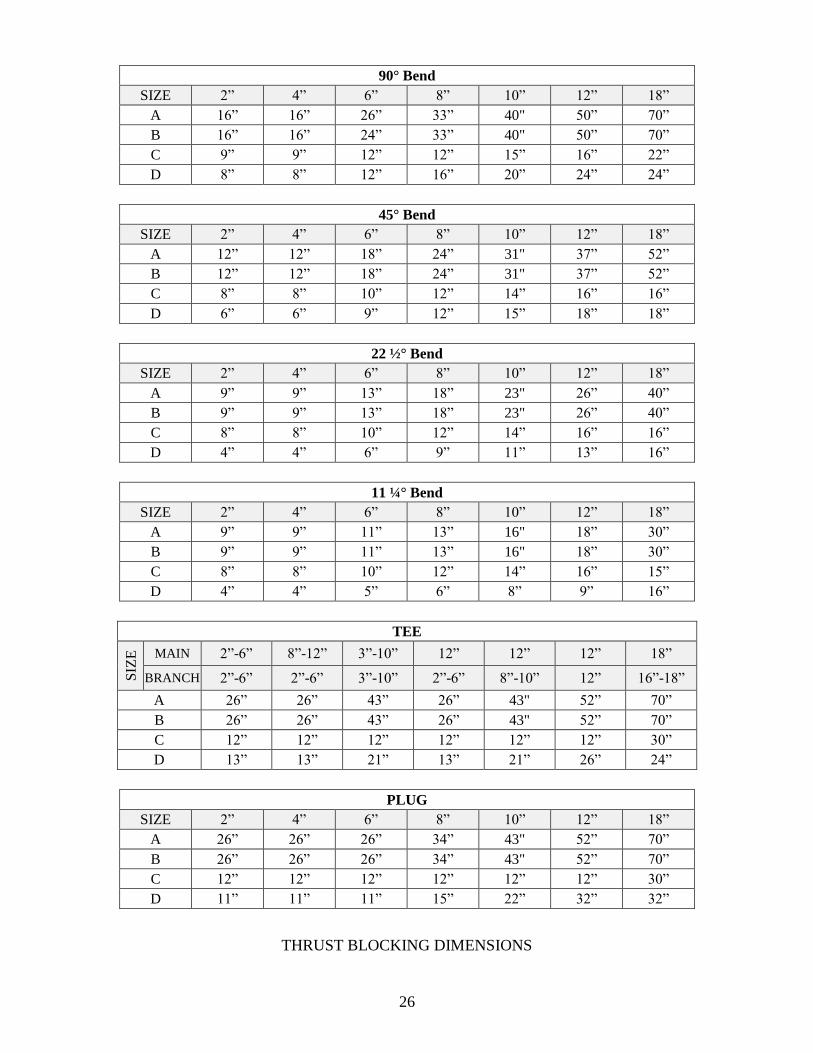
90° Bend
SIZE 2” 4” 6” 8” 10” 12” 18”
A 16” 16” 26” 33” 40" 50” 70”
B 16” 16” 24” 33” 40" 50” 70”
C 9” 9” 12” 12” 15” 16” 22”
D 8” 8” 12” 16” 20” 24” 24”
45° Bend
SIZE 2” 4” 6” 8” 10” 12” 18”
A 12” 12” 18” 24” 31" 37” 52”
B 12” 12” 18” 24” 31" 37” 52”
C 8” 8” 10” 12” 14” 16” 16”
D 6” 6” 9” 12” 15” 18” 18”
22 ½° Bend
SIZE 2” 4” 6” 8” 10” 12” 18”
A 9” 9” 13” 18” 23" 26” 40”
B 9” 9” 13” 18” 23" 26” 40”
C 8” 8” 10” 12” 14” 16” 16”
D 4” 4” 6” 9” 11” 13” 16”
11 ¼° Bend
SIZE 2” 4” 6” 8” 10” 12” 18”
A 9” 9” 11” 13” 16" 18” 30”
B 9” 9” 11” 13” 16" 18” 30”
C 8” 8” 10” 12” 14” 16” 15”
D 4” 4” 5” 6” 8” 9” 16”
TEE
SIZ
E
MAIN 2”-6” 8”-12” 3”-10” 12” 12” 12” 18”
BRANCH 2”-6” 2”-6” 3”-10” 2”-6” 8”-10” 12” 16”-18”
A 26” 26” 43” 26” 43" 52” 70”
B 26” 26” 43” 26” 43" 52” 70”
C 12” 12” 12” 12” 12” 12” 30”
D 13” 13” 21” 13” 21” 26” 24”
THRUST BLOCKING DIMENSIONS
PLUG
SIZE 2” 4” 6” 8” 10” 12” 18”
A 26” 26” 26” 34” 43" 52” 70”
B 26” 26” 26” 34” 43" 52” 70”
C 12” 12” 12” 12” 12” 12” 30”
D 11” 11” 11” 15” 22” 32” 32”
27

28
29

30

31
32