Design-Construction of Precast Segmental Elevated Metro ... · Design-Construction of Precast...
15
Design-Construction of Precast Segmental Elevated Metro Line for Monterrey, Nuevo Le6n, Mexico Paul E. Mendorf, P.E. Senior Bridge Engineer J. Muller International San Diego, California Paul E. Mondorf obtained his M.Sc. engineering degree from the Technical University of Denmark, Copenhagen, where he was also assistant professor for 4 years. Over the major part of his career, Mr. Mondorf has been active in the design and construction of concrete structures around the world, such as concrete platforms for the North Sea, containment vessels for nuclear plants in France and Spain, and a large variety of bridges, including cast-in-place and precast segmental cantilever bridges. Recently, he was field construction engineer for the third Lake Washington Bridge, Washington, resident engineer for the CSX Escambia Bay Crossing, Florida and advisor to the general contractor who built the Metro in Monterrey, Mexico. Currently, he is resident engineer for the construction of the Los Angeles Metro Green Line segmental bridges. 42 In April1991, the first line of a mass transit rail system (Metro) for Monterrey, Nuevo Leon, Mexico, was brought into service. The 18.7 km (11.6 mile) line is an elevated bridge structure stretching over existing streets, consisting of segmental precast concrete spans that val}' in length up to a maximum of 47 m (154 ft). There are 17 elevated stations on the line, combining precast and cast-in-place concrete in the column- beam-slab structures and in the adjacent platforms. More than 6500 precast concrete bridge segments and 2700 other elements were cast in a specially designed, state-of-the-art plant located north of the city. Segments were match-cast on concrete beds long enough for each complete span, then delivered by trucks to the site, erected span-by-span on movable steel trusses and post-tensioned. The precast concrete box girder segments have pretensioned top slabs, 7.40 m (24 ft 3 in.) wide, that support two parallel, standard- gauge tracks. The electrified metro trains have up to four cars and operate at a design speed of 70 km/hr (43 miles/hr). The line was built by a consortium of three Monterrey contractors in just under 40 months from start of design to its opening. M onterrey is a rapidly growing industrial s tate capital of northern Mexico, 240 km (150 miles) south of the United States- Mexican border. Its present population is estimated at 3X million inhabitants. The city is fairly spread out among the foothills of the Sierra-Madre Moun- tains, and most residential areas are one-story family dwellings or gener- ally not more than four- to five-story multi-family houses. The city has a good system of radial and belt roads for rapid vehicular traf- fic. However, the larger part of the population is totally dependent on pub- lic transportation, consisting mostly of buses which increase air and noise pol- lution and inner city congestion. The construction of a mass transit PCI JOURNAL
Transcript of Design-Construction of Precast Segmental Elevated Metro ... · Design-Construction of Precast...

Design-Construction of Precast Segmental Elevated Metro Line for Monterrey, Nuevo Le6n, Mexico
Paul E. Mendorf, P.E. Senior Bridge Engineer J. Muller International San Diego, California
Paul E. Mondorf obtained his M.Sc. engineering degree from the Technical University of Denmark, Copenhagen, where he was also assistant professor for 4 years. Over the major part of his career, Mr. Mondorf has been active in the design and construction of concrete structures around the world , such as concrete platforms for the North Sea, containment vessels for nuclear plants in France and Spain, and a large variety of bridges, including cast-in-place and precast segmental cantilever bridges. Recently, he was field construction engineer for the third Lake Washington Bridge, Washington, resident engineer for the CSX Escambia Bay Crossing, Florida and advisor to the general contractor who built the Metro in Monterrey, Mexico. Currently, he is resident engineer for the construction of the Los Angeles Metro Green Line segmental bridges.
42
In April1991, the first line of a mass transit rail system (Metro) for Monterrey, Nuevo Leon, Mexico, was brought into service. The 18.7 km (11.6 mile) line is an elevated bridge structure stretching over existing streets, consisting of segmental precast concrete spans that val}' in length up to a maximum of 47 m (154 ft). There are 17 elevated stations on the line, combining precast and cast-in-place concrete in the columnbeam-slab structures and in the adjacent platforms. More than 6500 precast concrete bridge segments and 2700 other elements were cast in a specially designed, state-of-the-art plant located north of the city. Segments were match-cast on concrete beds long enough for each complete span, then delivered by trucks to the site, erected span-by-span on movable steel trusses and post-tensioned. The precast concrete box girder segments have pretensioned top slabs, 7.40 m (24 ft 3 in.) wide, that support two parallel, standardgauge tracks. The electrified metro trains have up to four cars and operate at a design speed of 70 km/hr (43 miles/hr). The line was built by a consortium of three Monterrey contractors in just under 40 months from start of design to its opening.
M onterrey is a rapidly growing industrial state capital of northern Mexico, 240 km
(150 miles) south of the United StatesMexican border. Its present population is estimated at 3X million inhabitants. The city is fairly spread out among the foothills of the Sierra-Madre Mountains, and most residential areas are one-story family dwellings or gener-
ally not more than four- to five-story multi-family houses.
The city has a good system of radial and belt roads for rapid vehicular traffic. However, the larger part of the population is totally dependent on public transportation, consisting mostly of buses which increase air and noise pollution and inner city congestion.
The construction of a mass transit
PCI JOURNAL

Fig. 1. A portion of the completed 18.7 km (11.6 mile) elevated Metro line for Monterrey, Mexico. All spans use segmental precast concrete construction .
system was proposed. Underground as well as surface and aerial solutions were examined; however, preference was given to a light rail system, placed on an overhead structure built within the existing street area, a solution which combines efficiency and economy.
In January 1987, the state of Nuevo Leon decided to build a first line, to be 18.7 km ( 11.6 miles) long, and in November of the same year, a public utility called METRORREY was created to transform that decision into reality (see Fig. 1). Construction time
SIMPLY SUPPORTED SPANS
CONTINUOUS SPANS
z 0 Vi ~ ....
~ ~~CAST -IN-PLACE w!
~NEOPRENE
i BEARINGS i i
' 'I' '
1 .. 30m
~NEOPRENE i BEARINGS
i I i
15-36m
m-CAST-IN-PLACE I i
"-POT i j BEARINGS i i i i i c: !:J !
.. I .. 47m
Fig. 2. Schematic arrangement for simply supported and continuous spans.
March-April 1993
c:p .. I
I i
i i
ctJ
.. I ..
was initially set at 24 months. This artic le presents the conceptual
design and structural features of the Metro system, discusses the precasting operations, and describes the erection and post-tensioning techniques used on the segmental spans.
30m
z Q Vl z .... <z ~ ! 5 w!-, I
i i c~
.. I
43

~ N ci
E !!l
I lO
<t. I
7.4m TYPICAL AT TANGENT
i 1.08/. 2.786m
HORIZONTAL 1.08/.
EB. TRACK
<t.
1.828m 2.786m i ~ WB. TRACK
3.00m <l
CATENARY POSTS NOT SHOWN
CAST -IN-PLACE PLINTHS
!
I
i I i ! I I I I ·----,----·
i i i !
i i i i i i J,
I ' I
DRAIN
r-----------~------1-------L----------, I ' I
! II, ! I I I I ! J I ,---~---, ,--1--, I ... ___ 1 r----------------1 1 ~--J
I I ! i ! I I I f I I l I I : I ' I I I I I ~----j I y----~ l, __ .. t---' l ... __ f'-'
i i
Fig. 3. Cross section of typical, single-cell, segmental box girder bridge deck and foundation .
DESIGN FEATURES The Metro line will be served by
electric train, each comprising two, three or four articulated vehicles. Each vehicle is 30 m (98 ft) long on three bogies (trucks). The vehicles have conventional wheels which roll on a normal gauge track, using rails of 57 kg/m (115 lb/yd) welded in lengths up to 2700 m (8860 ft).
44
The double track will be anchored to longitudinal plinths placed directly on the supporting bridge structure. The current, 1500-volt direct current, wi ll be served by overhead catenaries, suspended from posts placed on the bridge deck alongside the track. Furthermore, on either side of the track, the bridge deck will carry sig nal posts, cable conduits, maintenance
catwalks and concrete parapets. The width of the bridge deck is
7.40 m (24.3 ft) on straight portions, increasing to 7. 85 m (25. 8 ft) on sharp curves.
Horizontal curves have a radius of not Jess than 250 m (820 ft) and the corresponding superelevation of the rails are achieved through over-height of the plinths. The longitudinal grade of the line generally does not exceed 2 percent, but in special zones, up to 3.5 percent is accepted. Vertical curves have a minimum radius of 2000 m (6560 ft).
Along the line, stations are placed approximately every 1100 m (3600 ft). The line has 13 cross-overs between tracks and two emergency turn-outs. Maintenance shops are placed at the end of the line, where a descent to ground level is provided.
The train has a design speed of 70 krn/hr (43 miles/hr). The weight of a vehicle is 40 t (44 Tons) dead load and 27 t (30 Tons) live load, corresponding to the weight of about 400 passengers. The structu re is designed for bogie loads of 24 and 20 t (26 and 22 Tons), respectively, spaced approximately 10m (33 ft) center-to-center, with a coefficient of impact of 0.2 . In passenger areas, a uniformly distributed live load of 500 kg/m 2
( 100 I b/ft 2) has been
taken into account. Derailment load has been considered according to the Sacramento Light Rail Project, Design Criteria 1982, Chapter 7.
The bridge structure has been designed according to AASHTO Standard Specifications. Monterrey is considered to be in a non-seismic area.
Soil conditions along the line can be summarized as alluvial deposits overlaying sedimentary rock . The alluvions are of varying compositions and properties, but fine clays and deposits of sand and gravel prevail ; in some areas, strata of caliche or strongly cemented conglomerates occur. The sedimentary rock is generally limestone and shale. The ground water level within the area varies significantly, but typically it is more than 10 m (33 ft) below the surface.
In order to simplify the foundation design, it proved convenient to apply zoning. In about 70 percent of the cases, the columns of the bridge struc-
PCI JOURNAL

TYPICAL SEGMENT
.·.·.·.·>.·:·.·.·>.·.· ·.<·.·.·.·.<·>:·.·.·>.<·.·.
! I
~ : : ·-:-:-".;.;.:-:-:-:-:-:-:-:-:-:-:-:-:-;.
I
3.00m
PIER SEGMENT
.·.·.·. ·.·.·.· .·.·.·.·.·.·
i
:·:::-::.:_::·.::::.:.:·:::
IE l.~Om ;.1
Fig. 4. Details of typical span segments and pier segments.
ture could be supported on footings placed directly on a layer of stiff clay, compact sandy grave l, cemented gravel or shale at depths which could be excavated from the surface. In the remainder of the cases, the columns had to be supported on piles bearing on alluvions or on rock at depths of 15 to 25m (49 to 82ft).
Monterrey has an arid climate characterized by extremely hot summers and short but sometimes very cold winters . The temperatures range from +46° to -10°C (115 ° to l4°F), and sudden changes of about 25°C (45°F) are common.
THE BRIDGE STRUCTURE The basic structure has raft footings
or bored pile foundations, single columns 5 to 15 m (16 to 49 ft) high with massive shafts and flared out capitals, and a bridge deck formed as a single box girder, which carries the
March-April 1993
plinths for the rails. The major part of the structure was
conceived as simply supported spans (see Fig. 2) with span lengths varying from 15 to 36m (49 to 118ft); the average span has a length of 27 m (89 ft). The span lengths were determined mainly by the conditions at street level for the placement of foundations and columns. Moreover, the structure includes four groups of continuous spans, 30-47- 30m (98- 154- 98ft) long, fitted to accommodate the crossings of particularly wide avenues (see Fig. 2).
In the design of the structure, standardization was attempted wherever possible. Columns are all the same type, with only two different sizes of shafts and capitals. They were cast-inplace in steel forms.
The box girder cross section is held constant throughout the bridge (see Fig. 3). It has a depth of 2.13 m (7 ft), inclined webs 0.305 m (1 ft) thick, a 7.40 m (24ft 3 in.) wide top slab can-
tilevered out on both sides of the basic box, and a 2.44 m (8 ft) wide bottom slab . Top and bottom slabs have a thickness of 0.20 m (8 in.). Heavy diaphragms are provided at both ends of simply supported spans and over all intermediate piers of continuous spans.
The box girders for the deck are all segmental precast concrete, requiring (basically) two different types of segments. Typical span segments are 3 m (9.8 ft) long, and pier segments are 1.2 or 1.5 m (3.9 or 4.9 ft) long (see Fig. 4), in slightly different versions for simply supported and continuous spans, respectively.
The box girder is post-tensioned longitudinally by tendons anchored in the diaphragms. Over the major part of their lengths, tendons are outside the concrete, but inside the box girder, they are lodged in polyethylene tubing. The tendons are deviated at specific locations through steel pipes embedded in concrete deviation blocks , cast
45

monolithically with the box segments. The top slabs of the box girders are
pretensioned transversely and the segments are reinforced with mild steel reinforcement using an average amount of 120 kg/m3 (7.5 pet) for typical segments and 160 kg/m3 (10 pet) for pier segments. The concrete design strength is 35 MPa (5000 psi). The box girder was conceived for matchcast dry joints with keys provided on all matching surfaces.
Curvature in plan is achieved by the box girder axis being a chord to the curve from pier to pier but by varying the widths of the cantilevered deck slabs to allow the segment edges to follow the curving track.
The bridge deck rests on bearings, two at either end of each simply supported span. In general, the bearings are laminated neoprene pads on reinforced concrete plinths cast on top of the capitals. For intermediate piers of continuous spans, and for certain simply supported spans with horizontal curves, cross-overs or turn-outs, pot bearings are provided.
The bridge deck is anchored against overturning by heavy, galvanized steel rods, anchored at their upper ends by 50 mm (2 in .) thick steel plates embedded in the pier segments and at their lower ends by steel plates bearing against the concrete in blackouts in the piers (see Fig. 5).
The bridge structure includes 17 Metro stations (see Fig. 6), each one basically a 30 m (98 ft) long central hall built as a combination of precast and cast-in-place concrete columnbeam-slab structure. On both sides of the central hall, there is a 45 m (148 ft) long platform area, built as continuous two- or three-span segmental bridges of the same cross section as the rest of the bridge. However, these segmental spans are equipped with brackets to support precast cross beams which carry the cantilevered passenger platforms (see Fig. 7).
In certain areas , due to restrictions at ground level or for traffic reasons, the single columns were replaced by straddle bents. Each such bent is composed of two columns and, typically, they are located at either side of the street. A transfer post-tensioned concrete girder of double-I cross sec-
46
tion is used to carry the bridge deck (see Fig. 8).
Where the structure crosses the Santa Catarina River (see Fig. 9) , the columns have been skewed to ease the flow of water, thereby requiring a second type of column capital. Except for that feature, those columns are similar to the other ones on land although they have heavier foundations. It may be recalled that in September 1988, after the area had been hit by Hurricane Gilberto, the normally dry Santa Catarina River suffered heavy floods with a flow rate of 12,000 m3/sec (425,000 ft3/sec), resulting in many casualties.
The structure comprises a total of 619 segmental spans requiring 6503 segments, namely, 5265 typical span segments and 1238 pier segments.
VERTICAL SECTION PARALLEL TO BRIDGE AXIS
HORIZONTAL SECTION
I ·-1-.
I I
Table 1 summarizes the key dimensions and major components of Line 1 of the light rail project.
In addition to the features of the viaduct described, Line 1 comprises two localized applications of other structural concepts, introduced as a large scale test of a combination of various systems.
PRECASTING PLANT In order to manufacture the large
number of precast concrete components required by the project, a precasting plant was installed (see Fig. 10) in a 16 ha (39 .5 A) area about 20 km (12 miles) north of Monterrey.
For casting this type of bridge segment, basically two different methods were available: (1) casting segments in
PT TENDONS
HOLD DOWN RODS A 36, Dmax =1 %"
EMBEDDED STEEL PLATE
IN CURVE MAX=2. 73 •
Fig. 5. Bearing and anchorage details at ends of segmental box girders.
PCI JOU RNAL

STATIONS:
f
z 0 iii ~ .... a... I ~ xo LIJ""')
PLATFORM AREA
I
r-.- NEOPRENE r'--POT
I [ __ ]
z 0 iii
1 ..
z I
"' z ~ l o LIJ...,
BRGS. BRGS.
I [ __ ]
22.5m . I. 22.5m
PLATFORM AREA I I
r'--NEOPRENE r--POT r-.--por BRGS. BRGS. BRGS.
I I I [ _ _ ] [_ , [_ .. J -·
1: 15m .1. 15m .1. 15m
z Cf. z ~ I ~ ~ ~ CENTRAL RC BUILDING ~ ~ ~~~ I ~ ~ ~
- -- -T-r--NEOPRENE i
BRGS. . ,_SPLIT COLUMN
[_ .. J t
.I .
!
30m
-
C .... J t
.I.
z Cf. z ~ I ~ ~ ~ CENTRAL RC BUILDING ~ ~ ~~~ I ~~~
-- - -t---r---NEOPRENE i
BRGS. , I-SPLIT COLUMN
[ _ _ ] t !
• I. I
30m
120m
[ .... J t .I.
Fig. 6. Schematic arrangement of Metro stations and platforms.
SEE DETAIL
I I I I -------1
I I I I
Fig. 7. Details of continuous bridge to provide platforms at the 17 Metro stations.
March-April 1993
z 0 iii
PLATFORM AREA I
~~--~~~ LIJ""')
I I r , [_ .. J ...... .,j
22.5m .I. 22.5m .. I
z 0 iii
PLATFORM AREA I I
~~--~ ~ ~ LIJ""')
I I I [ __ ] L , :::: :J -·
15m .1 .. 15m .1. 15m :I
PLATFORM
TRANSVERSE TENDONS
CROSS BEAM
POT BEARING
HOLD DOWN RODS HT STEEL, Dmax =1%"
47

Fig. 8. Portion of completed structure showing use of straddle bents instead of single piers.
Fig. 9. The Metro line crossing of the normally dry Santa Catarina River is on high-level, skewed columns.
Table 1. Summary of key dimensions and major components of Line 1 project.
Length of Line I
Length of segmental bridge
Number of stations
Number of spans
Number of segments: Typical segments Pier segments
Total
[ 11.3 m'/each] [8.4 m'/each]
Number of other precast elements:
Cross beams 11 .9 to 2 m'/each] Platform slabs [2.6 to 3.3 m'/each l Sidings [0.3 m'/each]
Quantity of concrete: Foundations Columns Box girders Station platform areas
Number of segment molds: Molds for typical segments Molds for pier segments Total
18.7 km
17.6 km
17
619
5265 1238 6503
1008 796 940
55,000 10,000 70,000 5,000
26 14 40
m' m' m' m '
Theoretical capacity, segments per day 0.9 (26 + 14/2) 30
Number of erection girder sets:
Typical rates of construction:
Precasting of typical segments Precasting of pier segments Total
Erection, spans per week per girder set
Note: l km = 0.62 m1 les; I m' = 1.31 yd'-
8
20 per day 5 per day
25 per day
2
Fig. 10. Overall view of the large precasting plant located outside of Monterrey.
48 PCI JOURNAL

STRESSING FRAME
ADJUSTMENT~--------~-L---4--~ SCREWS
CONCRETE CASTING BED
Fig. 11. Segments were cast in molds comprising exte rior and interior forms that traveled on rails on the long casti ng benches.
stationary molds, moving them from casting position to the countermold position and from there to storage, or (2) the segments could be cast on long benches, in which case the segments remain stationary while the forms move along the benches from one casting position to another.
Both methods apply match-casting, which means that each segment is cast against the previous one to ensure a perfect fit of each segment against its neighbor when erected. The longbench method was selected for simplicity of execution and for its economy, because a high number of reuses of the benches was anticipated.
The long benches were made of reinforced concrete. Their lengths ranged from 39 to 53 m (128 to 174ft) to allow the casting of all types of spans in full length. Each bench consisted of a 12 m (39 ft) wide slab, 0.35 m (1.1 ft) deep, with a 2.41 m (7.9 ft) wide central part raised 0.50 m (1.6 ft) over the remainder of the slab. The entire bench was cast on soil which had been properly prepared and compacted to prevent differential settlement under the heavy loads of the segments.
The plant had 20 long benches arranged in four lines with four or six benches in each line. The lines were separated about 23 m (75 ft) center-tocenter to allow for crane tracks, temporary storage of cages, installation of conveyor belts, access for concrete
March-April 1993
trucks and passage of travelifts transporting segments to storage. The benches were equipped with water, electricity and steam, and they were served by tower cranes running alongside between two lines of benches. Three steam generators, each with 850,000 kcal!br (3 .37 x 106 Btu/hr) capacity, provided steam for curing the freshly cast elements.
The molds for the segments each consisted of two lateral forms fixed on trolleys, a central core also fixed on a trolley, and one or two bulkheads (see Fig. 11). All trolleys had wheel blocks equipped with adjustment screws. The trolleys moved on rai Is cast into the lower parts of the long bench, whereas
the segments themselves were cast directly on the raised central part of the bench. The lateral forms were fitted tight against the raised part of the bench and kept in place by tie rods passing through that part of the bench. Heavy steel frames for stressing the transverse prestressing strand in the top slab were placed on top of the mold.
The plant had 26 molds for typical segments and 14 for pier segments with 40 percent more stressing frames for each type of segment. Also, several pier segment molds had special extra bulkheads and cores for pier segments of contin uous spans. Each bench could have several forms working on it simultaneously.
Fig. 12. Reinforcing ba r cage for a typical segment.
49

For the preparation of reinforcing bar cages (see Fig. 12), a central yard was laid out, equipped with cutters and benders and stands for typical segment and pier segment cages, respectively. The cages were brought forward by truck from the steel fixing area to the benches.
The concrete materials were supplied from two weighing stations installed in the plant and mixed in trucks. Each station had four truck mixers at its disposal. The concrete was transferred from the trucks to the molds by conveyor belts which were moved from one bench to another (see Fig. 13). There were five conveyor belts for casting segments simultaneously in four or five locations . In the molds, only internal vibration was used.
The plant was equipped with three tower cranes and several mobile cranes. Two travelifts were available to lift segments from the benches (see Fig. 14) and load them on low-boys for their transportation to the storage area. There were also two crawler cranes to handle segments in the remote storage area. The plant was capable of storing up to 2000 segments (see Fig. 15).
The plant also had a concrete repair area for patching segments which came from the production area with minor faults. The area was equipped with a stand (see Fig. 16) for inspecting the undersides of the segments and a stand capable of load testing the top slab of segments.
The plant was designed to produce daily 26 typical span segments and seven pier segments, which meant a production of 360m3 (470 yd3
) of concrete and processing 45 t (50 Tons) of reinforcing bars.
PRECASTING OPERATIONS
The plant layout was based on the production of typical span segments in a 24-hr cycle and pier segments in a 48-hr cycle. For both types of segments, the significant factor was the early concrete strength of 28 MPa (4000 psi) required for the release of the transverse strands. This strength had to be obtained in 16 hrs in order to leave the remaining 8 hrs for the turn-
50
Fig. 13. A segment casting using a conveyor belt to move concrete from truck mixer to mold.
Fig. 14. Travelifts handle and transport completed segments in the plant.
around of the mold, that is, stripping one segment and casting the next segment in the same mold.
To obtain this high early strength with Type I cement, superplasticizers had to be used to increase the workability of the concrete and to reduce the water-cement ratio. Steam curing was applied to accelerate the strength increase.
A typical work cycle on a mold began with a geometry check of the previous segment and breaking of cylinders to ascertain whether the required strength, 28 MPa (4000 psi), had been obtained to allow the cutting of strands. Then, the form was stripped and moved forward to a new position where it was cleaned and oiled. The matching end face of the
previous segment was covered with a bond breaker . The reinforcing bar cage and embedded items were placed by crane between the already adjusted side forms, whereafter the central core was brought in and the bulkhead was fixed to the side forms.
Transverse prestressing strands were strung between the reinforcing bars of the top slab and stressed against the steel frames supported on extensions of the lateral forms. Once the form had been adjusted and checked, it was ready for the next casting. These operations typically lasted 5 to 61> hrs, leaving 1 to 1 Y, hrs for the casting which was usually completed in 1 hr.
All operations on the molds were staggered by groups of four, aiming at having four molds ready for casting
PCI JOURNAL

Fig. 15. Completed segments in storage at the plant.
Fig. 16. Repair stand for correcting minor faults on completed segments.
every 1 Y2 hrs . Typically, the castings started in the late morning and continued for about 12 hrs.
Production of a span started with casting the first typical segment, Tl, which required two bulkheads. Then, the typical segments (Segments T2, T3, T4, etc.) were added on in one direction, all using the same bulkhead. A pier segment was cast in the same direction against the last typical one, using a counter bulkhead. Pier Segment No. 1 was cast against Segment T 1 in the other direction, also requiring a counter bulkhead. In some cases, it was found convenient to cast Pier Segment No. 1 early in the process so that removal of segments could begin and production of the next span could start even before the
March-April 1993
first one had been completed. Segments were steam cured starting
at about 3 hrs after the end of the casting, raising the temperature slowly to a maximum of 65 °C (150°F) . The steam was turned off about 10 hrs after the end of the casting to allow the temperature to drop slowly until the forms were opened.
The crushed rock used for both the coarse and fine aggregate was such that it was not always possible to obtain the required strength of 28 MPa ( 4000 psi) in 16 hrs. Therefore, in order to not slow down production, several extra stressing frames were acquired. If the strength necessary to release the strands was not achieved in time but a strength in the range of 28 to 21 MPa ( 4000 to 3000 psi) was
Table 2. Key dates in design and construction schedule.
Operation Date
Detailed structural design , start January 1988
Acquisition of the ground for the precasting plant July 1988
First segment cast October 1988
Erection of first span March 1989
End - Precasting of segments March 1990
End- Erection of spans August 1990
Inauguration April25 , 1991
found, the frame was left on that segment and the strands were not cut. However, the form was stripped and brought forward , and a spare frame was made available for stressing the next segment.
Precasting proceeded for 15 months. The first 4 months of the precasting operation could be considered a learning period. Molds were still being delivered and installed, equipment was tuned, and crews were being trained, organized and multiplied to bring the plant up to full capacity. Similarly, the last 2 months were a phasing-out period. Molds were taken out of service for overhaul and moth-balling, and the crews were gradually reduced or switched to other activities, such as the production of precast concrete members for the passenger platform areas.
ERECTION The key dates of construction are
summarized in Table 2. The segments were transported on
low-boys (see Fig. 18) from the precasting plant to the erection sites where they were erected by the spanby-span method.
Using this technique, the segments for one span were placed on erection girders, adjusted into position so that matching keys fitted perfectly, and stressed together by post-tensioning tendons. In this manner, the span became self supporting. The weight of the span was then transferred to the permanent bridge bearings, and the trusses were separated from the span and shifted forward to be ready for the
51

TYPICAL SEGMENT COUNTER BULKHEAD
TYPICAL SEGMENT BULKHEAD LONG BENCH
_ INNER FORM CARRIAGE
STRESSING FRAME~:FORM CARRIAGE ~ULKHEAO
I ,_ PIER SEGMENT BULKHEAD
PIER SEGMENT STRESSING FRAME PIER SEGMENT SIDE FORM CARRIAGE PIER SEGMENT COUNTER BULKHEAD
PIER SEGMENT BULKHEAD PIER SEGMENT STRESSING FRAME PIER SEGMENT SIDE FORM CARRIAGE PIER SEGMENT COUNTER BULKHEAD
Fig. 17. Sequence of casting segments for a complete span on the long casting benches.
erection of the next span. The erection girders were modular
steel trusses of triangular cross section, one fitting under each wing of the segments (see Fig. 19). The length of the trusses could be adjusted from 24 to 49 m (79 to 161 ft) to allow
spans of all lengths to be erected. Trusses were supported on steel
brackets which were suspended from the capitals of the bridge piers and clamped around the pier shafts (see Fig. 20). For spans of 36 m (118 ft) or more, intermediate supports were re-
Fig. 18. A completed segment is hauled on a low-boy trailer from plant to bridge site.
52
quired. These were modular steel towers which could be installed directly on the pavement.
Trusses, pier brackets and intermediate towers were made specially to accommodate all span lengths and all pier configurations . For example, square and skew piers, straddle bents at one or both ends of the span, spans in curve and continuous spans in the platform areas of the stations all had to be accommodated.
To be able to shift the trusses forward from one typical span to the next, each truss was equipped with a hook at its front end. At its rear end, the truss had a C-hook, which fitted around the segment wing and was suspended from a trolley on the top deck. Thus, the trusses could be pulled by a winch while the crane lifted the front end and the rear end rolled over the span which had just been erected.
In general , pier brackets were installed on the columns first , ahead of the arrival of the trusses. Erection of
PCI JOURNAL
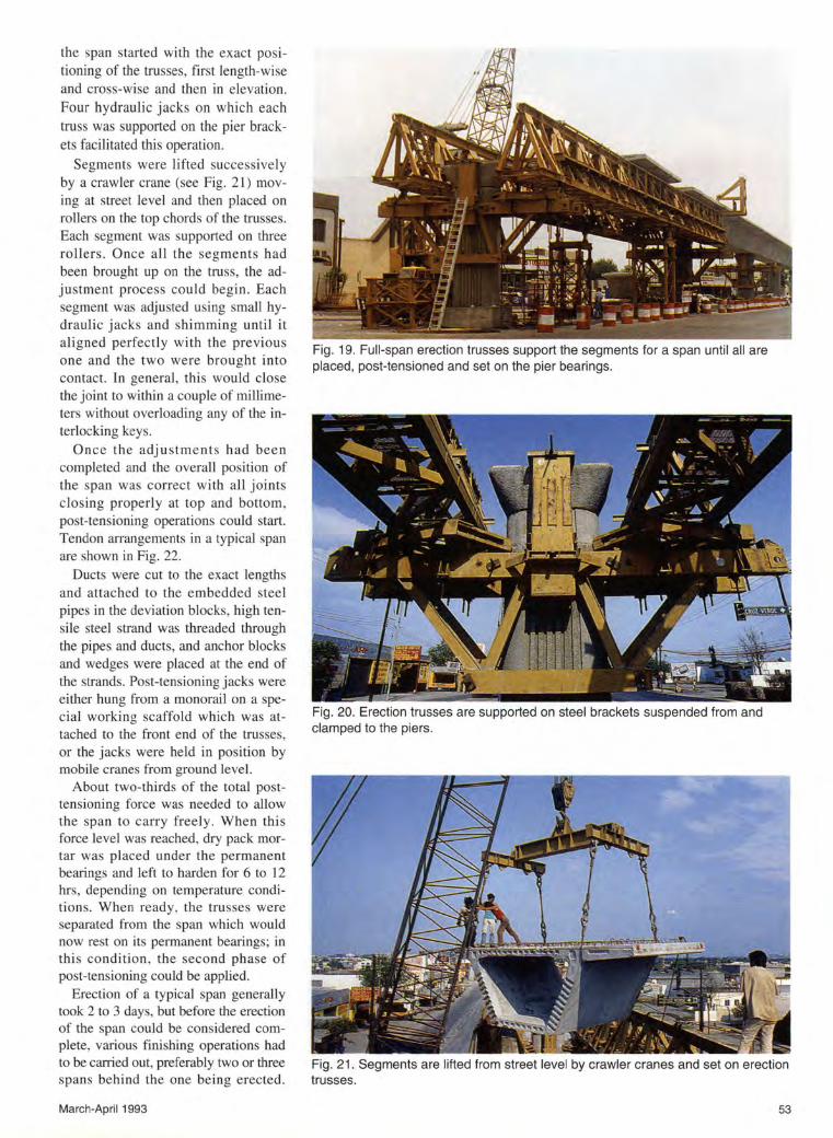
the span started with the exact positioning of the trusses, first length-wise and cross-wise and then in elevation. Four hydraulic jacks on which each truss was supported on the pier brackets facilitated this operation.
Segments were lifted successively by a crawler crane (see Fig. 21) moving at street level and then placed on rollers on the top chords of the trusses. Each segment was supported on three rollers . Once all the segments had been brought up on the truss, the adjustment process could begin. Each segment was adjusted using small hydraulic jacks and shimming until it aligned perfectly with the previous one and the two were brought into contact. In general , thi s would close the joint to within a couple of millimeters without overloading any of the interlocking keys.
Once the adj ustments had bee n completed and the overall position of the span was correct with all joints closing properly at top and bottom, post-tensioning operations could start. Tendon anangements in a typical span are shown in Fig. 22.
Ducts were cut to the exact lengths and attached to the embedded steel pipes in the deviation blocks, high tensile steel strand was threaded through the pipes and ducts, and anchor blocks and wedges were placed at the end of the strands. Post-tensioning jacks were either hung from a monorail on a special working scaffold which was attached to the front end of the trusses, or the jacks were held in position by mobile cranes from ground level.
About two-thirds of the total posttensioning force was needed to allow the span to carry free ly. When this force level was reached, dry pack mortar was placed under the permanent bearings and left to harden for 6 to 12 hrs, depending on temperature conditions. When ready , the trusses were separated from the span which would now rest on its permanent bearings; in this condition, the second phase of post-tensioning could be applied.
Erection of a typical span generally took 2 to 3 days, but before the erection of the span could be considered complete, various finishing operations had to be caiTied out, preferably two or three spans behind the one being erected.
March-April 1993
Fig. 19. Full-span erection trusses support the segments for a span until all are placed, post-tensioned and set on the pier bearings.
Fig. 20. Erection trusses are supported on steel brackets suspended from and clamped to the piers.
Fig. 21 . Segments are lifted from street level by crawler cranes and set on erection trusses.
53

ELEVATION CROSS SECTION
(l SPAN
----- -------------- -------------
PLAN
::::::::::::::::::::: . ::::::::::::::::::::::::::::::: :; :::::::::: :::::::::::::::::::::::::::::::::;::::::::: ::::::::::::::::::::::::::::::::::::::::::: ::::::::::::::::::::::::::::::::::::::::::: :: ~?? : ~ ~ ~ ~ ~}:
---------- ·.·:~: ... ·, · ·· :· · ·:~ ·::
Fig. 22. Arrangement of post-tensioning tendons inside the box segments of half of a typical span.
Fig. 23. A portion of the Metro line crossing the beltway.
54
These operations included grouting of tendons, installation of hold-down rods, cleaning of bearings, and possibly a few concrete repairs, filling of block-outs and other jobs.
The groups of large continuous spans, 30- 47 - 30 m (98- 154- 98ft), were also erected span-by-span, but they included various cast-in-place closure joints to compensate for any geometrical imperfections that might have occurred. Fig. 23 shows a portion of a continuous span crossing the beltway.
The groups of small continuous spans for platform areas of the stations, 15- 15- 15 m (49- 49- 49ft) or 22.5 - 22.5 m (74 - 74 ft), were generally erected in one operation with the erection girders spanning all of the 45 m (148 ft). These spans had closure joints to be cast-in-place over the intermediate piers only. Timing for the erection of these spans was particularly difficult because the central part of the stations had to be built before the adjacent segmental structure could be erected.
To finish the job on schedule, the contractors had eight sets of erection girders, each complete with three pier brackets and generally two intermediate towers - a total of about 1200 t (1300 Tons) of structural steel.
The precast concrete cross beams
PCI JOURNAL

for the platform areas of the stations were erected by mobile cranes operating at ground level (see Figs. 7 and 24). Cross beams were lifted successively and their lower ends were keyed into brackets which protrude from the segments at the level of their lower slabs. At the level of the segment wings, the cross beams were initially attached by bolts and temporary cable slings.
Subsequently, the temporary connection was replaced by permanent post-tensioning tendons anchored in the two cross beams which form a pair. For additional safety, the lower end of each cross beam was secured against the segment web through a heavy steel rod, properly grouted after stressing. Where the precast concrete cross beam rests on the segment bracket, the joint was filled with epoxy, either applied at the moment of erection or injected after erection.
Two sets of hanging scaffolds were used. One set was used for access to the brackets and the lower ends of the cross beams during their erection. Another set was used for access to the anchors of the post-tensioning tendons during their stressing.
Erection of the platform areas was completed by placing precast concrete sidings and slabs, along with the casting in place of joints and end parts. The basic operation of platform area erection was usually done in about 10 days per station.
Fig. 25 shows a completed portion of the Metro line in an urban setting. As can be seen in the photograph, curvature can be built into the structure.
Coordination between plant personnel and erection crew was quite demanding. For the segments, a minimum age of 2 weeks was deemed mandatory before erection . All segments were manufactured to a predetermined location in the structure and the as-built distance between piers was checked before the last typical segment of a span was cast in order to make any necessary adjustments.
The erectors had to face numerous constraints, such as interface with other contractors and between different erection firms, traffic restrictions in town, weather inclemencies, unforeseeable minor misfits, break-
March-April 1993
Fig. 24. In the platform areas, precast concrete cross beams are attached to the box girder segments.
ages and repairs which required decisions at higher levels, and delayed deliveries of special items such as pot bearings.
Such constraints often led to a supplementary shift of erection girders from one location to another. Therefore, it was found advantageous to let the plant always keep an appropriate lead time over the erection, with a considerable number of segments in storage at all times in order to be able to face a variety of potential scenarios.
CONCLUDING REMARKS
In retrospect, the precast structural system and method of construction
have proven to be ideal for this project. The various logistic and construction problems encountered on the job were relatively minor and quickly solved.
The structural solution adopted in Monterrey is cost efficient, not as much through its quantities of construction materials as through its high degree of repetition and its simple and sturdy structures, which proved quick and easy to erect.
The original cost estimate of the project was about 400,000 million pesos, which meant some 200 million U.S. dollars at the time. However, during the planning and design phase, the line was extended, some technical features were modified and (especially) the maintenance shop was enlarged
Fig. 25. A portion of the completed Metro line.
55

and relocated to be able to serve the larger part of the full network. Therefore , the estimate underwent several adjustments . The final cost of Line 1 [comprising 18.7 km (11.6 miles)], not including the cars, was established at about 237 million U.S. dollars. Considering this, it can be stated that there was fairly good agreement between the original budget estimate and the final cost.
The cost of the Line 1 civil works was 117 million U.S. dollars, out of which 84 million were for the precast concrete segmental viaduct alone, excluding shop and stations. This cost breaks down to about $650/m 2
($60/ft2) .
The structural solution described here sati sfied the client' s design requirements and construction schedule. The structural design was carefully developed and the structure erected in just 2~ years.
The solution appears to have met the goals of the owner. The Metro was opened on schedule and, all in all, it has been well received by the community . Six months after the start of revenue operation, daily ridership reached 90,000 on weekdays and 60,000 on Sundays, compared to a maximum capacity of 150,000 to 200,000.
Whether a mass transit system like this should be underground, on the ground or aerial will always be open to discussion. Certainly, each type of system has its lirilltations and advantages. In this particular case, the aerial
56
solution was probably the only one which had any chance of getting built with the available funding and within the specified time period.
In general, the new Metro, the service it provides and the structure as it is placed in its urban surroundings has been met with public satisfaction.
The full Metro network is expected to comprise 72 km (45 miles), to be built within 15 years. Its total cost is hard to predict because itineraries and types of construction have not been finally selected for all parts of the project. Line 2 will be 10 km (6 miles) long and will be partly in tunnel, cut and cover. It has a budget of 425 million U.S. dollars, of which 300 million is for civil work. Work on Line 2 is now in progress.
ACKNOWLEDGMENT The author is grateful to METROR
REY, particularly to Ing. Manuel Gonzalez Fernandez , Director General , Ing. Javier de Ia Garza Vidal, Director de Construccion, Ing. Rolando Valle Favela, Director de Ingenieria, and to CONSTRUMETRO, especially to Ing. Felix Bermudez Benitez, Director General, and Ing. Luis Rene Gonzalez y Gutierrez, Director de Construccion y Planta Prefabricados. To all, the author is indebted for the honor and professional challenge it has meant to participate in this impressive project, and for the perrillssion granted to publish this article.
Credits
Owner: METRORREY, State of Nuevo Le6n, Mexico
General Contractor: CONSTRUMETRO, a consortium of:
• Tiasa (Protexa), Monterrey
• Constructora Maiz Mier, Monterrey
• Constructora Lobeira, Monterrey
Consultants:
• LRTC, DUsseldorf, Germany Feasibility of the project, horizontal and vertical alignment
• J. Muller International, Paris, France Structural design of the segmental viaduct, design of special casting and erection equipment, technical assistance on site
• Construmetro Ingenieria, Monterrey, Mexico Foundation and column design
• Reid Crowther Inc., Vancouver, Canada Design of the trackwork
• Inplat, Mexico Maintenance shop design
Suppliers:
• Algoma Steel , Inc. , Toronto, Canada Rails
• Serto/Ohio Brass, United States Catenary
• Concarril, Mexico Vehicles
• Siemens, AG, Germany Train control, signals , telecommunication systems
PCI JOURNAL