Design, Construction, and Maintenance of Bridge Decks ... glass fiber-reinforced polymer (GFRP) bars...
72
Technical Report Documentation Page 1. Report No. FHWA/TX-05/9-1520-P2 2. Government Accession No. 3. Recipient's Catalog No. 5. Report Date February 2005 4. Title and Subtitle DESIGN, CONSTRUCTION, AND MAINTENANCE OF BRIDGE DECKS UTILIZING GFRP REINFORCEMENT 6. Performing Organization Code 7. Author(s) David Trejo, Francisco Aguiñiga, Ray W. James, and Peter B. Keating 8. Performing Organization Report No. Product 9-1520-P2 10. Work Unit No. (TRAIS) 9. Performing Organization Name and Address Texas Transportation Institute The Texas A&M University System College Station, Texas 77843-3135 11. Contract or Grant No. Project 9-1520 13. Type of Report and Period Covered Product 12. Sponsoring Agency Name and Address Texas Department of Transportation Research and Technology Implementation Office P. O. Box 5080 Austin, Texas 78763-5080 14. Sponsoring Agency Code 15. Supplementary Notes Project performed in cooperation with the Texas Department of Transportation and the Federal Highway Administration. Project Title: FRP Reinforcing Bars in Bridge Decks URL: http://tti.tamu.edu/documents/9-1520-P2.pdf 16. Abstract Fiber-reinforced polymers (FRP) are being increasingly used in the construction industry. One application is to use FRP bars as reinforcement in concrete. Because glass fiber-reinforced polymer (GFRP) bars are now being used, guidance is needed on how to design, construct, and maintain reinforced concrete structures containing this reinforcement. This report provides a discussion of design issues related to GFRP- reinforced bridge decks and is followed by a design example. Recommendations for possible modifications to the 1998 American Association of State Highway Officials (AASHTO) LRFD Bridge Design Specifications are provided. In addition, some guidelines on the construction and maintenance of GFRP- reinforced systems are provided. It should be noted that more research and field work is needed to provide standardize guidelines. This report provides guidance using the information available and the user should use sound engineering judgment in the design, construction, and maintenance of GFRP-reinforced structures. 17. Key Words GFRP, Strength, Design, Construction, Maintenance, Strength Deterioration. 18. Distribution Statement No restrictions. This document is available to the public through NTIS: National Technical Information Service Springfield, Virginia 22161 http://www.ntis.gov 19. Security Classif.(of this report) Unclassified 20. Security Classif.(of this page) Unclassified 21. No. of Pages 72 22. Price Form DOT F 1700.7 (8-72) Reproduction of completed page authorized
Transcript of Design, Construction, and Maintenance of Bridge Decks ... glass fiber-reinforced polymer (GFRP) bars...

Technical Report Documentation Page 1. Report No. FHWA/TX-05/9-1520-P2
2. Government Accession No.
3. Recipient's Catalog No. 5. Report Date February 2005
4. Title and Subtitle DESIGN, CONSTRUCTION, AND MAINTENANCE OF BRIDGE DECKS UTILIZING GFRP REINFORCEMENT
6. Performing Organization Code
7. Author(s) David Trejo, Francisco Aguiñiga, Ray W. James, and Peter B. Keating
8. Performing Organization Report No. Product 9-1520-P2 10. Work Unit No. (TRAIS)
9. Performing Organization Name and Address Texas Transportation Institute The Texas A&M University System College Station, Texas 77843-3135
11. Contract or Grant No. Project 9-1520 13. Type of Report and Period Covered Product
12. Sponsoring Agency Name and Address Texas Department of Transportation Research and Technology Implementation Office P. O. Box 5080 Austin, Texas 78763-5080
14. Sponsoring Agency Code
15. Supplementary Notes Project performed in cooperation with the Texas Department of Transportation and the Federal Highway Administration. Project Title: FRP Reinforcing Bars in Bridge Decks URL: http://tti.tamu.edu/documents/9-1520-P2.pdf 16. Abstract
Fiber-reinforced polymers (FRP) are being increasingly used in the construction industry. One application is to use FRP bars as reinforcement in concrete. Because glass fiber-reinforced polymer (GFRP) bars are now being used, guidance is needed on how to design, construct, and maintain reinforced concrete structures containing this reinforcement. This report provides a discussion of design issues related to GFRP-reinforced bridge decks and is followed by a design example. Recommendations for possible modifications to the 1998 American Association of State Highway Officials (AASHTO) LRFD Bridge Design Specifications are provided. In addition, some guidelines on the construction and maintenance of GFRP-reinforced systems are provided. It should be noted that more research and field work is needed to provide standardize guidelines. This report provides guidance using the information available and the user should use sound engineering judgment in the design, construction, and maintenance of GFRP-reinforced structures. 17. Key Words GFRP, Strength, Design, Construction, Maintenance, Strength Deterioration.
18. Distribution Statement No restrictions. This document is available to the public through NTIS: National Technical Information Service Springfield, Virginia 22161 http://www.ntis.gov
19. Security Classif.(of this report) Unclassified
20. Security Classif.(of this page) Unclassified
21. No. of Pages 72
22. Price
Form DOT F 1700.7 (8-72) Reproduction of completed page authorized


DESIGN, CONSTRUCTION, AND MAINTENANCE OF BRIDGE DECKS UTILIZING GFRP REINFORCEMENT
by
David Trejo, PhD Associate Professor and Associate Researcher
Texas A&M University and Texas Transportation Institute
Francisco Aguiñiga, PhD Assistant Professor
Texas A&M University Kingsville
Ray W. James, PhD Associate Professor and Manager, Highway Structures Program
Texas A&M University and Texas Transportation Institute
and
Peter B. Keating, PhD Associate Professor and Associate Researcher
Texas A&M University and Texas Transportation Institute
Product 9-1520-P2 Project Number 9-1520
Project Title: FRP Reinforcing Bars in Bridge Decks
Performed in Cooperation with the Texas Department of Transportation
and the Federal Highway Administration
February 2005
TEXAS TRANSPORTATION INSTITUTE The Texas A&M University System College Station, Texas 77843-3135


v
DISCLAIMER
The contents of this report reflect the views of the authors, who are responsible for the facts and the accuracy of the data presented herein. The contents do not necessarily reflect the official view or policies of the Federal Highway Administration (FHWA) or the Texas Department of Transportation (TxDOT). This report does not constitute a standard, specification, or regulation. The researcher in charge of the project was Dr. David Trejo.

vi
ACKNOWLEDGMENTS This project was performed in cooperation with the Federal Highway Administration and the Texas Department of Transportation. This report was written by Drs. David Trejo, Francisco Aguiñiga, Ray W. James, and Peter B. Keating. Financial support for the research was provided by the Federal Highway Administration, Texas Department of Transportation, and the Texas Transportation Institute. The authors wish to express their gratitude to: Project Coordinator:
Ronald E. Koester, P.E., TxDOT, Waco District Project Director:
Timothy E. Bradberry, P.E., TxDOT, Bridge Division Project Advisors:
Don Harley, P.E., Federal Highway Administration Mary Lou Ralls, P.E., Retired State Bridge Engineer, TxDOT Joe Chappell, P.E., TxDOT, Amarillo District Mark Bloschock, P.E., TxDOT, Bridge Division Kevin Pruski, P.E., TxDOT, Bridge Division Robert Sarcinella, TxDOT, Construction Division Paul McDad, TxDOT, Construction Division Tom Yarbrough, TxDOT, Research Division

vii
TABLE OF CONTENTS
Page
LIST OF FIGURES .............................................................................................. viii
LIST OF TABLES ................................................................................................ ix
I. INTRODUCTION ................................................................................................ 1
II. ACI 440.1R-03 DESIGN GUIDELINES: REVIEW AND PROPOSED
MODIFICATIONS ............................................................................................... 3
ACI 440.1R-03 Section 7.2 Design Material Properties ................................ 3
ACI 440.1R-03 Section 8.3.1 Cracking.......................................................... 6
ACI 440.1R-03 Section 8.3.2 Deflections ...................................................... 9
ACI 440.1R-03 Section 8.3.3 Calculations of Deflection (Direct Method) ... 10
ACI 440.1R-03 Section 11.1 Development Length of a Straight Bar ............ 13
Minimum Concrete Cover .............................................................................. 15
Introduction to Design Example ..................................................................... 15
Design Example.............................................................................................. 16
III. PROPOSED REVISIONS TO THE AASHTO LRFD
BRIDGE DESIGN SPECIFICATIONS ............................................................... 41
IV. RECOMMENDED CONSTRUCTION GUIDELINES FOR THE USE
OF GFRP REINFORCEMENT............................................................................ 55
V. RECOMMENDED MAINTENANCE GUIDELINES FOR GFRP
REINFORCED CONCRETE STRUCTURES..................................................... 57
VI. SUMMARY .......................................................................................................... 59
REFERENCES...................................................................................................... 61
viii
LIST OF FIGURES
Figure Page
1 Crack Comparison for a 1.21-Inch Concrete Cover ................................................ .9
2 Design Example ..................................................................................................... 17
3 Tying of GFRP Bars .............................................................................................. 56
4 Chair Placement for GFRP Reinforcement ............................................................ 56

ix
LIST OF TABLES
Table Page
1 Tensile Strength Results and Predicted Values......................................................... 5

1
I. INTRODUCTION
Corrosion of steel reinforcement embedded in concrete transportation structures
results in significant costs and negatively impacts the traveling public. Researchers and
engineers have been searching for alternative materials that do not exhibit the typical
expansion of the steel corrosion products that result in cracking and spalling of the
concrete cover. These cracks and spalls reduce the integrity of the reinforced concrete
structure and can significantly reduce the ride quality of the concrete bridge deck.
Corrosion of fiber-reinforced polymers (FRP) does not exhibit expansion of the
corrosion product and has been identified as a potential material for use in reinforced
concrete structures. This report provides guidance on the design, construction, and
maintenance of bridge decks reinforced with glass fiber-reinforced polymer (GFRP)
concrete reinforcement. This report reviews the American Concrete Institute (ACI)
440.1R-03 (2003), Guide for the Design and Construction of Concrete Reinforced with
FRP Bars (herein referred to as the ACI 440.1R-03 design and construction guidelines),
and suggests modifications as needed. The report also provides proposed revisions to
the 1998 American Association of State Highway and Transportation (AASHTO) Load
and Resistance Factor Design (LRFD) Bridge Design Specifications. Recommended
construction and maintenance guidelines for GFRP-reinforced concrete are also
provided.
It should be noted that many issues related to the use of GFRP reinforcement require
further research; the results presented here are from Report 9-1520-3 Characterization of
Design Parameters for Fiber Reinforced Polymer Composite Systems, by Trejo et al.
(2003). It should also be noted that the three materials evaluated in Report 9-1520-3
were from a single lot from each of three manufacturers. It was assumed that the
materials from these single lots and manufacturers represent of the GFRP materials
present in industry. The reader and/or user must use good judgment and engineering
when applying the following recommendations.


3
II. ACI 440.1R-03 DESIGN GUIDELINES: REVIEW AND
PROPOSED MODIFICATIONS
This section reviews the ACI 440.1R-03 design and construction guidelines
(2003) as they relate to the results obtained in the research reported in Report 9-1520-3
(Trejo et al. 2003). The ACI 440.1R-03 design and construction guidelines present
information on the history and use of fiber-reinforced polymer (FRP) reinforcement, a
description of the material properties of FRP, and committee recommendations relative
to the construction of concrete structures reinforced with FRP bars. This document also
includes recommended material requirements, construction practices, and design
recommendations. Only those sections of the ACI 440.1R-03 design and construction
guidelines that the researchers believe could be improved and are related to the use of
glass fiber-reinforced polymer (GFRP) bars in bridges are reviewed.
The first section of the ACI 440.1R-03 design and construction guidelines to be
reviewed is Section 7.2, Design Material Properties, specifically as related to the
environmental reduction factors proposed by the guidelines to be applied to the tensile
strength of FRP bars reinforced with glass fibers. A review of Section 8.3,
Serviceability, follows. The serviceability section review includes cracking (subsection
8.3.1) and deflections (addressed in subsections 8.3.2 and 8.3.2.3). Section 11.1,
regarding the development length of straight bars, is also reviewed. Finally, comments
are provided in regard to minimum concrete cover.
ACI 440.1R-03 SECTION 7.2 DESIGN MATERIAL PROPERTIES
Section 7.2 of the guidelines indicates that the material properties provided by
the manufacturer should be reduced to account for long-term environmental exposure.

4
The guidelines recommend that the tensile strength should be determined by: *fuEfu fCf = (1)
where,
ffu = Design tensile strength of FRP, considering reduction for service
environment (ksi),
CE = Environmental reduction factor,
f*fu = Guaranteed tensile strength of an FRP bar defined as the mean tensile
strength of a sample of test specimens minus three times the standard
deviation (f*fu = fu,ave – 3σ) (ksi),
fu,ave = Average tensile strength of FRP bars.
The environmental reduction factors given in the guidelines for GFRP bars are
0.8 and 0.7 for concrete not exposed to earth and weather and for concrete exposed to
earth and weather, respectively. The guidelines indicate that the environmental
reduction factors are conservative estimates that account for temperature effects, as long
as the material is not used at temperatures higher than the glass transition temperature of
the polymer employed to manufacture the bars.
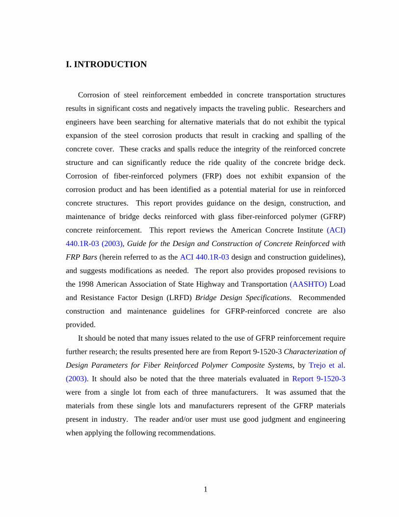
The average tensile strengths of the unexposed specimens of the tension tests in
Report 9-1520-3 (Trejo et al. 2003) are presented in column 2 of Table 1. The
unexposed tensile strengths, standard deviations, and guaranteed tensile strengths are
shown in columns 3 and 4, respectively, of Table 1. Also shown in columns 5 and 6 of
Table 1 are the design tensile strengths computed using Equation 1. The smallest
measured tensile strength from any of the exposure conditions at 50 weeks is shown in
column 7 of Table 1. Column 8 shows the guaranteed tensile strength (f*fu = fu,ave – 3σ)
obtained from the measured exposure data at 50 weeks. Column 9 presents the predicted
average residual tensile strength computed using a value of λ = 0.0057 (best fit to
guaranteed tensile strength) computed using the method described in the tensile strength
degradation analysis section of the moisture absorption test results in Report 9-1520-3
(Trejo et al. 2003), for a five-year exposure period. Column 10 shows the predicted
5
residual tensile strength using a value of λ = 0.006 (curve fit to lowest measured data
points) described in the tensile strength degradation analysis section of the moisture
absorption test results in Report 9-1520-3 (Trejo et al. 2003), for a five-year exposure
period.
According to comparisons made with the research conducted by Sen et al. (2002)
as discussed in Report 9-1520-3 (Trejo et al. 2003) in the tensile strength degradation
analysis section, the results predicted that a value of λ 0.0057 (best fit to guaranteed
tensile strength) can be considered as the upper bound residual tensile strengths. The
predictions are considered as upper bound residual strength values because the bars were
exposed unstressed, and as indicated by Sen et al., the application of a sustained stress to
GFRP bars causes larger strength reductions with time when the bars are unstressed.
Table 1. Tensile Strength Results and Predicted Values.
(1) (2) (3) (4) (5) (6) (7) (8) (9) (10)P 84,588 2,456 77,219 61,775 54,053 68,616 59,995 52,868 53,798
V1 88,507 7,951 64,655 51,724 45,258 70,969 63,559 55,317 56,290V2 74,471 2,598 66,676 53,341 46,673 56,609 54,863 46,544 47,363
Guaranteed 50 weeks f* fu (psi)
Predicted 5 years f u
(psi)
Bar type
Tensile strength (psi) Smallest 50 weeks f u (psi)
Predicted 5 years
f* fu (psi)f u, avg
unexp.S.D.
unexp.f* fu
unexp.f fu
(C E =0.8)f fu
(C E =0.7)
Comparing the values presented in columns 6 and 8 of Table 1 shows that the
values of column 6 are only 11, 40, and 18 percent lower than the values of column 8.
The values of ffu represent the design tensile strength obtained following ACI 440.1R-03,
and include an environmental reduction factor for exterior exposure that is intended to
account for strength reductions suffered by GFRP bars over the life of the structure. The
results shown indicate that the design strength is slightly larger than the guaranteed
tensile strength after only one year of exposure for bar type P. Since the reductions in
strength shown in column 8 were determined for unstressed specimens, it is expected
that the guaranteed tensile strength will be lower in actual service conditions, where the
GFRP bars are stressed.

6
A comparison of columns 6 and 9 of Table 1 show that the five-year predicted
guaranteed tensile strengths are equivalent to 0.98, 1.22, and 1.00 of the design strengths
presented in column 6. This indicates that the GFRP bars evaluated in the research can
have a guaranteed residual tensile strength close to the design strength after only five
years of unstressed exposure. As already noted, GFRP bars are expected to have a lower
residual tensile strength when they are stressed in service conditions.
Glaser et al. (1983) conducted a 10-year study on the life estimation of
S glass/epoxy composites under sustained tensile load. The specimens were kept at a
temperature between 68 °F and 82 °F and a relative humidity between 24 and 37 percent.
The researchers found that the residual tensile strength of the specimens continuously
decreased with time, even beyond five years, at these relatively low humidity levels.
Based on the observations reported in 9-1520-3 (Trejo et al. 2003) and because the
tensile strength of GFRP bars in stressed service conditions is expected to either level off
or continue to degrade after one year of exposure, the results indicate that the
environmental reduction factors given by the ACI 440.1R-03 design and construction
guidelines may not be conservative.
As indicated in the tensile strength degradation analysis section of the moisture
absorption test shown in Report 9-1520-3 (Trejo et al. 2003), it is difficult to make valid
predictions for long periods of time with the limited exposure times studied. It is
therefore necessary to carry out exposure tests over longer periods of time to make
reliable long-term behavior predictions.
The application of the strength reduction factors is presented in a design example
later.
ACI 440.1R-03 SECTION 8.3.1 CRACKING
The ACI 440.1R-03 design and construction guidelines indicate that FRP bars
are corrosion resistant and, as a result, the maximum crack width limitation can be
relaxed when corrosion of the reinforcement is the main reason for crack-width

7
limitations. The guidelines recommend using maximum crack width limits of 0.02 inch
for exterior exposure and 0.028 inch for interior exposure.
The results section of the cracking of the concrete slabs test in Report 9-1520-3
(Trejo et al. 2003) indicated that maximum crack width increases with concrete cover.
However, as indicated by Beeby (1978), although the crack width on the surface of the
concrete is a function of concrete cover, the crack width at the level of the reinforcement
could be approximately the same. Thus, it would be better to specify a maximum
surface crack width limit that is a function of concrete cover if the degradation of the
GFRP bar depends on the crack width at the surface of the bar rather than at the surface
of the concrete. However, until research that relates the degradation of GFRP bars to
crack width at the surface of the concrete and at the surface of the GFRP bar is available,
no recommendations can be made.
The ACI 440.1R-03 design and construction guidelines recommend using
Equation 8-9b (or 8-9c) to estimate the maximum crack width of FRP-reinforced
concrete elements. As described in the results section for the cracking of concrete slabs
test in Report 9-1520-3 (Trejo et al. 2003), the following expression yields a good fit to
the experimental data:
3max 09.0 AdfW cf ⋅⋅= β (2)
where,
Wmax = most probable maximum crack width
β = h2/h1,
h1 = Distance from the centroid of the reinforcement to the neutral axis (inch),
h2 = Distance from the extreme tension fiber to the neutral axis (inch),
ff = Stress in the reinforcement (ksi),
dc = Bottom cover measured from the center of lowest bar (inch),
A = Twice the difference between the total and effective depths multiplied by the
width of the section (effective area of concrete surrounding the main
reinforcement) divided by the number of bars (inch2).
8
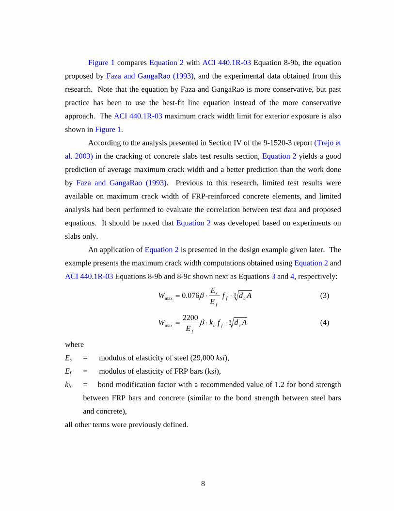
Figure 1 compares Equation 2 with ACI 440.1R-03 Equation 8-9b, the equation
proposed by Faza and GangaRao (1993), and the experimental data obtained from this
research. Note that the equation by Faza and GangaRao is more conservative, but past
practice has been to use the best-fit line equation instead of the more conservative
approach. The ACI 440.1R-03 maximum crack width limit for exterior exposure is also
shown in Figure 1.
According to the analysis presented in Section IV of the 9-1520-3 report (Trejo et
al. 2003) in the cracking of concrete slabs test results section, Equation 2 yields a good
prediction of average maximum crack width and a better prediction than the work done
by Faza and GangaRao (1993). Previous to this research, limited test results were
available on maximum crack width of FRP-reinforced concrete elements, and limited
analysis had been performed to evaluate the correlation between test data and proposed
equations. It should be noted that Equation 2 was developed based on experiments on
slabs only.
An application of Equation 2 is presented in the design example given later. The
example presents the maximum crack width computations obtained using Equation 2 and
ACI 440.1R-03 Equations 8-9b and 8-9c shown next as Equations 3 and 4, respectively:
3max 076.0 Adf
EE
W cff
s ⋅⋅= β (3)
3max
2200 AdfkE
W cfbf
⋅⋅= β (4)
where
Es = modulus of elasticity of steel (29,000 ksi),
Ef = modulus of elasticity of FRP bars (ksi),
kb = bond modification factor with a recommended value of 1.2 for bond strength
between FRP bars and concrete (similar to the bond strength between steel bars
and concrete),
all other terms were previously defined.

9
The results of the design example show that Equations 2 and 4 yield similar maximum
crack widths. In addition, the maximum crack widths obtained with Equations 2 and 4
are larger, and therefore more conservative, than those obtained with Equation 3.
0.00
0.02
0.04
0.06
0.08
0.10
0 5000 10000 15000 20000 25000 30000 35000
FRP bar stress measured at midspan (psi)
Max
imum
cra
ck w
idth
(in.
)
ExperimentACI limitACI Eq. 8-9bFazaLeast SquaresC = 0.09
Figure 1. Crack Comparisons for a 1.21-Inch Concrete Cover.
ACI 440.1R-03 SECTION 8.3.2 DEFLECTIONS
The ACI 440.1R-03 design and construction guidelines require that deflections
be limited in FRP-reinforced concrete flexural members. The guidelines follow the
deflection limitations of the ACI 318 building code (2000), in which the deflections of
reinforced concrete elements under immediate and sustained static loads are limited.
However, the deflection limitations of the ACI 440.1R-03 design and construction
guidelines and the ACI 318 code do not apply to dynamic loads, such as earthquakes,
transient winds, or vibration of machinery.
Faza
ACI Limit
ACI Eq. 8-9b

10
The results of the research reported in Report 9-1520-3 (Trejo et al. 2003) on the
cyclic loading of concrete beam tests indicate that the deflections of beams subjected to
2 million cycles of loading with a GFRP bar stress range of 18.9 ksi increased by 78
percent. This increment was computed from a least-squares best-fit line to the data.
Therefore, the deflection increase due to cyclic loading is significant and should be
accounted for in the ACI 440.1R-03 design and construction guidelines. In the absence
of more test data, the following equation can be used to estimate a lower bound of the
increase in long-term deflections due to cyclic loading:
0858.0)ln(0046.0 += ny (5)
Where,
y = beam deflection in inches,
n = the number of cycles.
The correlation coefficient between beam deflection and the number of cycles is R2 =
0.47. The slope of this equation can be used to compute deflections due to cyclic
loading of GFRP-reinforced concrete members.
An application of Equation 5 to estimate deflections due to cyclic loading is
shown in the example presented later. The design example computes the deflections of a
GFRP-reinforced concrete beam subjected to dead load and the application of 2 million
cycles of an alternating live load. The results show an initial deflection due to dead and
live load of 0.37 inches and a final deflection due to dead and live load of 0.47 inches
after 2 million cycles of the live load. This represents a 27 percent increase in deflection
due to cyclic load application.
ACI 440.1R-03 SECTION 8.3.3 CALCULATION OF DEFLECTION (DIRECT
METHOD)
This section of the ACI 440.1R-03 design and construction guidelines presents a
method to compute long-term deflections of FRP-reinforced concrete elements using
ACI 440.1R-03 Equation 8-14:

11
( ) ( )susishcp Δ=Δ + ξ6.0 (6)
where,
Δ(cp+sh) = Additional deflection due to creep and shrinkage under sustained loads (mm,
inch)
(Δi)sus = Immediate deflection due to sustained loads (service loads) (mm, inch)
ξ = Time-dependent factor for sustained load defined in the ACI 318 building
code (2000)
Equation 6 can predict smaller deflections than measured. Perhaps the biggest
advantage of Equation 6 is its simplicity. However, this equation does not specifically
account for creep of FRP bars. The method described in the creep section of Section IV
of the 9-1520-3 report for the computation of long-term deflection of GFRP-reinforced
concrete elements, which accounts for creep of GFRP bars, is proposed as an alternative
to Equation 6. The following equation can be used to compute the increment in
curvature:
( )eeee
ee
IABEMANB
−
−=Δ 2
'δδκ (7)
and the following equation can be used to compute the long-term deflection:
( )BCACLy κκκ ++= 1096
2
(8)
where,
Ae = area of the age-adjusted transformed section,
Be, = first moment of the age-adjusted transformed section about the top surface,
Ie = second moment of the age-adjusted transformed section about the top
surface, respectively.
κA, κB = curvatures at the supports,
κC = curvature at midspan.
Ae, Be, and Ie are the properties of the transformed area obtained using the age-adjusted
effective modulus, Ee, in the computation of the transformed area of the bonded
reinforcement.

12
Long-term deflection computations obtained with Equations 7 and 8 for a beam
with a 14 foot span are shown in the design example. The six-month dead load
deflections obtained with Equation 6 are 0.2 inches, and the six-month dead load
deflections obtained with Equations 7 and 8 are 0.61 inches. Thus, the six-month
deflection due to dead load computed with the newly proposed method from this
research is equal to three times the deflection obtained with Equation 8-14 from the ACI
440.1R-03 design and construction guidelines.

13
ACI 440.1R-03 SECTION 11.1 DEVELOPMENT LENGTH OF A STRAIGHT
BAR
The development length of a straight bar can be computed with Equation 11-3 of
the ACI 440.1R-03 design and construction guidelines as follows:
f
fubbf
fdl
μ4= (9)
where,
lbf = Basic development length (inch),
db = Bar diameter (inch),
ffu = Design tensile strength of FRP, considering reductions for service
environment (ksi),
μf = Bond strength between FRP bar and concrete (ksi).
The bond test results presented in Section IV of Report 9-1520-3 (Trejo et al.
2003) indicate that the bond strength of GFRP bars exposed to an environment with high
temperature and moisture was lower than the bond strength of specimens exposed
outdoors. In addition, the number of specimens exposed to controlled conditions that
failed by pullout was twice the number of specimens from the outdoor exposure group
that experienced pullout failures. However, this research included only a small number
of samples. The displacement recorded at the loaded end was larger, on average, for the
specimens exposed in temperature- and moisture-controlled conditions than for the
specimens exposed outdoors. These displacements are indications that bond strength
degrades over time. ACI 440.1R-03 Equation 11-3 recognizes that the tensile strength of
GFRP bars degrades with time and yields a smaller development length for a smaller
tensile strength. Nevertheless, when the bond strength degrades, the development length
increases. This fact may make Equation 9 unconservative. The development length of
Equation 9 should depend on the ratio of the rate of tensile strength degradation of
GFRP bars to the rate of bond strength degradation between the GFRP bars and

14
concrete. Additional research is needed to better estimate both the rate of tensile
strength degradation in a given environment and the rate of bond degradation in the
same environment. Perhaps the simplest way to account for the bond strength
degradation would be to apply an environmental reduction factor to the bond strength.
The bond strength of FRP bars in concrete depends on the compressive strength
of concrete, and tests have determined the denominator of Equation 9 to be
approximately 2.85 ksi. The ACI 440.1R-03 design and construction guidelines propose
using Equation 11-7:
2700fub
bf
fdl = (10)
where, ffu is the design tensile strength of GFRP. If the basic development length of an
FRP bar is computed with this equation, the bar should have adequate development
length at the end of its service life, since this equation includes an environmental
reduction factor (CE) in ffu. But, the bond length should be sufficient to develop the full
strength of the bar when the bar is put in service (fu,ave), as well as the strength of the bar
when it is close to the end of its service life (ffu). Therefore, the basic development
length obtained would be insufficient to develop the guaranteed tensile strength (f*fu =
fu,ave – 3 σ = ffu/CE) or the average tensile strength (fu,ave) of the GFRP bar when the
structure is put in service.
Until sufficient data are available to determine the rate of degradation of the
tensile strength and the rate of degradation of the bond strength, the average tensile
strength should be used in the computation of the basic development length for GFRP
bars, without reducing it by three standard deviations and without the application of the
environmental reduction factor as shown in Equation 10. Thus, this research
recommends that the following equation be used to compute the basic development
length and should replace Equation 11-7 in the ACI 440.1R-03 design and construction
guide (2003):

15
2700,aveub
bf
fdl = (11)
where the terms have already been defined.
A design example later shows the basic development lengths computed using
Equations 10 and 11 for No. 6 FRP reinforcement. Equation 10 yields a basic
development length of 17 inches and Equation 11 yields a basic development length of
26.4 inches. Thus, Equation 11 can yield basic development lengths 55 percent larger
than those obtained with Equation 10 (ACI 440.1R-03 equation, 11-7).
MINIMUM CONCRETE COVER
Results of the thermal expansion of the concrete slabs test indicate that using
0.75-inch diameter GFRP bars in 8-inch concrete bridge decks with clear covers of 1, 2,
and 3 inches would not crack under a temperature increase of 54 °F from the concrete
setting temperature for a concrete compressive strength of 5.88 ksi or higher. The fact
that 0.75-inch diameter GFRP bars could be safely used in concrete elements subjected
to temperature increases smaller than 54 °F for 1-, 2-, and 3-inch concrete covers could
be used in the ACI 440.1R-03 design and construction guidelines to determine minimum
concrete cover requirements. The concrete covers of 1, 2, and 3 inches are equivalent to
1.33, 2.66, and 4 bar diameters, respectively. From the results of this research it cannot
be determined whether the minimum concrete cover of 1 bar diameter recommended by
the ACI 440.1R-03 design and construction guidelines has problems with cracking due
to thermal expansion. However, it can be concluded from the results of this research that
a minimum concrete cover of 1.33 bar diameters would likely not cause thermal
expansion and cracking of typical bridge decks under normal environmental conditions.
INTRODUCTION TO DESIGN EXAMPLE
This section presents a design example that includes the recommended
modifications and/or verifications to the ACI 440.1R-03 design and construction
guidelines. A simply supported beam subjected to distributed dead and live loads is

16
designed for strength. The resulting design section is then checked to satisfy deflection,
maximum crack width, and creep rupture stress limits. The basic development length is
also computed. Finally, the beam deflections due to 2 million cycles of live load
applications are estimated.
DESIGN EXAMPLE
Objective
Design a simply supported rectangular concrete beam with a span of 14 ft. The
beam will be in the exterior of a structure. The beam should carry a service live load of
wLL = 1.2 kip/ft and a superimposed dead load of wSDL = 0.6 kip/ft. The deflection of the
beam at six months should not exceed l/240, and the instantaneous live load deflection
should not exceed l/360. GFRP bars reinforce the beam. The average tensile strength of
the GFRP bars is fu,ave = 96 ksi, the standard deviation is (S.D.) = 2.5 ksi, and the
guaranteed tensile strength is f*fu = 88.5 ksi. Other material properties are: Ef = 6,279 ksi
and cf ′ = 4 ksi. Assume the beam has adequate shear strength. Assume the beam will
be cured for 7 days and first loaded at 14 days of age. Compute the basic development
length of the GFRP reinforcement. Estimate the beam midspan deflection after 2 million
cycles of loading due to an alternating live load. Figure 2 shows a design based on the
modified ACI 440.1R-03 design and construction guidelines.

17
Design based on ACI 440.1R-03 design guidelines Design based on results from this research project
1. Estimate the beam size.
Estimate the depth of a simply supported reinforced concrete beam from Table 9.5(a) of the ACI 318 code. Deflections, however, need to be checked.
16lh ≅
( )( )in.ft14 ft 12
h 10.5 in.16
≅ =
Since GFRP bars have lower stiffness than steel bars, greater depth than steel-reinforced concrete may be required for deflection control Try h = 16 inches Try b = 10.5 inches
2. Factored load
Compute the distributed dead load: SWSDLDL www += . ( )( )
( )( )lb lb
DL ft ft2in.ft
10.5 in. 16 in.w 600 150 pcf 775
12= + =
Compute the total factored load LLDLu www 7.14.1 += .
( ) ( ) ftkip
ftkip
ftkip
uw 13.32.17.1775.04.1 =+=
2. Factored load
Compute the distributed dead load: SWSDLDL www += . ( )( )
( )( )lb lb
DL ft ft2in.ft
10.5 in. 16 in.w 600 150 pcf 775
12= + =
Compute the total factored load LLDLu www 7.14.1 += .
( ) ( ) ftkip
ftkip
ftkip
uw 13.32.17.1775.04.1 =+=
Figure 2: Design Example.

18
Design based on ACI 440.1R-03 design guidelines Design based on results from this research project
3. Compute the design strength.
For a beam located in an exterior space an environmental reduction factor (CE) of 0.7 is used. The design rupture strength is:
*fuEfu fCf =
( )( )fuf 0.7 88.5 ksi 62.0 ksi= =
3. Compute the design strength.
For a beam located in an exterior space an environmental reduction factor (CE) of 0.70 is used. The design rupture strength is:
*fuEfu fCf =
( )( )fuf 0.7 88.5 ksi 62.0 ksi= = 4. Determine the area of GFRP bars required for flexural strength. Factored moment demand at midspan:
8
2lwM uu =
( )( )2kipft
u
3.13 14 ftM 76.6 kip ft
8= = ⋅
Balanced reinforcement ratio:
fucuf
cuf
fu
cfb fE
Eff
+=
εε
βρ 1
'
85.0
( ) ( )( )( )( )
6279 0.00340.85 0.8562.0 6279 0.003 62.0fbρ =
+
0.0109fbρ = For a failure controlled by concrete crushing, the reinforcement ratio should be at least 1.4 ρfb. If ρf ≥ 1.4 ρfb, the strength reduction factor is 0.70.
4. Determine the area of GFRP bars required for flexural strength. Factored moment demand at midspan:
8
2lwM uu =
( )( )2kipft
u
3.13 14 ftM 76.6 kip ft
8= = ⋅
Balanced reinforcement ratio:
fucuf
cuf
fu
cfb fE
Eff
+=
εε
βρ 1
'
85.0
( ) ( )( )( )( )
6279 0.00340.85 0.8562.0 6279 0.003 62.0fbρ =
+
0.0109fbρ = For a failure controlled by concrete crushing, the reinforcement ratio should be at least 1.4 ρfb. If ρf ≥ 1.4 ρfb, the strength reduction factor is 0.70.
Figure 2: Design Example. (Continued)
19
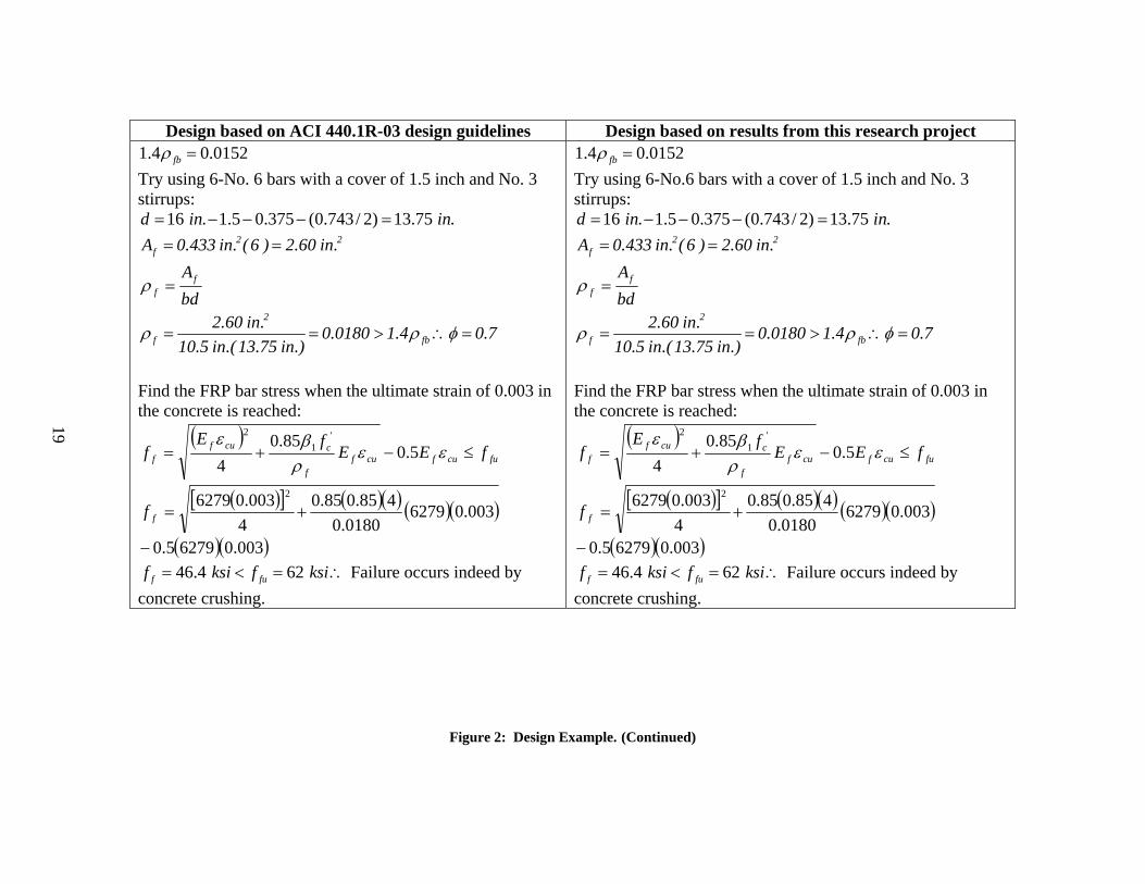
Design based on ACI 440.1R-03 design guidelines Design based on results from this research project 1.4 0.0152fbρ = Try using 6-No. 6 bars with a cover of 1.5 inch and No. 3 stirrups:
16 . 1.5 0.375 (0.743/ 2) 13.75 .d in in= − − − = 2 2
fA 0.433 in. (6 ) 2.60 in.= =
bdAf
f =ρ
2
f fb2.60 in. 0.0180 1.4 0.7
10.5 in.(13.75 in.)ρ ρ φ= = > ∴ =
Find the FRP bar stress when the ultimate strain of 0.003 in the concrete is reached:
( )fucufcuf
f
ccuff fEE
fEf ≤−+= εε
ρβε
5.085.0
4
'1
2
( )[ ] ( )( ) ( )( )003.062790180.0
485.085.04
003.06279 2
+=ff
( )( )003.062795.0− 46.4 62f fuf ksi f ksi= < = ∴ Failure occurs indeed by
concrete crushing.
1.4 0.0152fbρ = Try using 6-No.6 bars with a cover of 1.5 inch and No. 3 stirrups:
16 . 1.5 0.375 (0.743/ 2) 13.75 .d in in= − − − = 2 2
fA 0.433 in. (6 ) 2.60 in.= =
bdAf
f =ρ
2
f fb2.60 in. 0.0180 1.4 0.7
10.5 in.(13.75 in.)ρ ρ φ= = > ∴ =
Find the FRP bar stress when the ultimate strain of 0.003 in the concrete is reached:
( )fucufcuf
f
ccuff fEE
fEf ≤−+= εε
ρβε
5.085.0
4
'1
2
( )[ ] ( )( ) ( )( )003.062790180.0
485.085.04
003.06279 2
+=ff
( )( )003.062795.0− 46.4 62f fuf ksi f ksi= < = ∴ Failure occurs indeed by
concrete crushing.
Figure 2: Design Example. (Continued)

20
Design based on ACI 440.1R-03 design guidelines Design based on results from this research project Nominal Moment capacity:
2'59.01 bd
ff
fMc
ffffn ⎟⎟
⎠
⎞⎜⎜⎝
⎛−=
ρρ
( )( ) ( )( )2(0.0180)(46.4)0.0180 46.4 1 0.59 10 13.754nM ⎡ ⎤= −⎢ ⎥⎣ ⎦
nM 1385 kip in. 115.4 kip ft= ⋅ = ⋅ Provided moment capacity:
un MM ≥φ
( )nM 0.7 115.2 kip ft 80.8 kip ftφ = ⋅ = ⋅ 80.8 76.6n uM kip ft M kip ftφ = ⋅ ≥ = ⋅ ∴The section has
adequate flexural strength. Minimum reinforcement:
dbf
fA w
fu
cf
'
min,
4.5=
The minimum reinforcement requirement does not need to be checked because the section is over-reinforced.
Nominal Moment capacity: 2
'59.01 bdf
ffM
c
ffffn ⎟⎟
⎠
⎞⎜⎜⎝
⎛−=
ρρ
( )( ) ( )( )2(0.0180)(46.4)0.0180 46.4 1 0.59 10 13.754nM ⎡ ⎤= −⎢ ⎥⎣ ⎦
nM 1385 kip in. 115.4 kip ft= ⋅ = ⋅ Provided moment capacity:
un MM ≥φ
( )nM 0.7 115.2 kip ft 80.8 kip ftφ = ⋅ = ⋅ 80.8 76.6n uM kip ft M kip ftφ = ⋅ ≥ = ⋅ ∴The section has
adequate flexural strength. Minimum reinforcement:
dbf
fA w
fu
cf
'
min,
4.5=
The minimum reinforcement requirement does not need to be checked because the section is over-reinforced.
Figure 2: Design Example. (Continued)
21
Design based on ACI 440.1R-03 design guidelines Design based on results from this research project
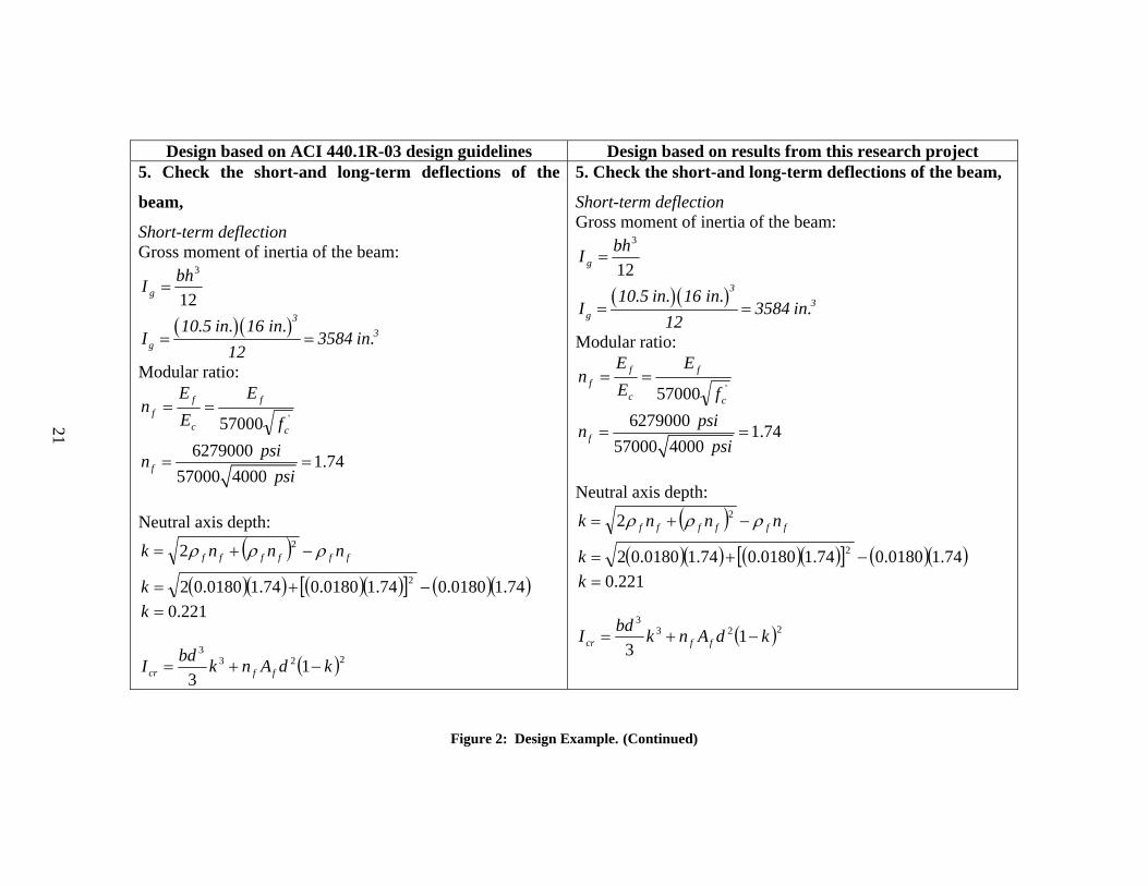
5. Check the short-and long-term deflections of the
beam,
Short-term deflection Gross moment of inertia of the beam:
12
3bhI g =
( )( )33
g
10.5 in. 16 in.I 3584 in.
12= =
Modular ratio:
'57000 c
f
c
ff
f
EEE
n ==
6279000 1.7457000 4000f
psinpsi
= =
Neutral axis depth:
( ) ffffff nnnk ρρρ −+= 22
( )( ) ( )( )[ ] ( )( )74.10180.074.10180.074.10180.02 2 −+=k 221.0=k
( )2233
13
kdAnkbdI ffcr −+=
5. Check the short-and long-term deflections of the beam,
Short-term deflection Gross moment of inertia of the beam:
12
3bhI g =
( )( )33
g
10.5 in. 16 in.I 3584 in.
12= =
Modular ratio:
'57000 c
f
c
ff
f
EEE
n ==
6279000 1.7457000 4000f
psinpsi
= =
Neutral axis depth:
( ) ffffff nnnk ρρρ −+= 22
( )( ) ( )( )[ ] ( )( )74.10180.074.10180.074.10180.02 2 −+=k 221.0=k
( )2233
13
kdAnkbdI ffcr −+=
Figure 2: Design Example. (Continued)

22
Design based on ACI 440.1R-03 design guidelines Design based on results from this research project ( )( ) ( ) ( )( ) ( )223
3
221.0175.1360.274.1221.03
75.1310−+=crI
4crI 613 in.=
Compute the reduction coefficient for deflections using αb = 0.50 for FRP bars having the same bond strength as steel bars:
⎟⎟⎠
⎞⎜⎜⎝
⎛+= 1
s
fbd E
Eαβ
62790.50 1 0.60829000d
ksiksi
β⎛ ⎞
= + =⎜ ⎟⎝ ⎠
Moment due to dead load plus live load:
8
2lwM LLDLLLDL
⋅= +
+
( )( )20.775 1.2 1448.4
8
kip kipft ft
DL LL
ftM kip ft+
+= = ⋅
Cracking moment:
2
5.7 '
hIf
yIf
M gc
t
grcr ==
( )( ) ( ) ( )( ) ( )2233
221.0175.1360.274.1221.03
75.1310−+=crI
4crI 613 in.=
Compute the reduction coefficient for deflections using αb = 0.50 for FRP bars having the same bond strength as steel bars:
⎟⎟⎠
⎞⎜⎜⎝
⎛+= 1
s
fbd E
Eαβ
62790.50 1 0.60829000d
ksiksi
β⎛ ⎞
= + =⎜ ⎟⎝ ⎠
Moment due to dead load plus live load:
8
2lwM LLDLLLDL
⋅= +
+
( )( )20.775 1.2 1448.4
8
kip kipft ft
DL LL
ftM kip ft+
+= = ⋅
Cracking moment:
2
5.7 '
hIf
yIf
M gc
t
grcr ==
Figure 2: Design Example. (Continued)
23
Design based on ACI 440.1R-03 design guidelines Design based on results from this research project
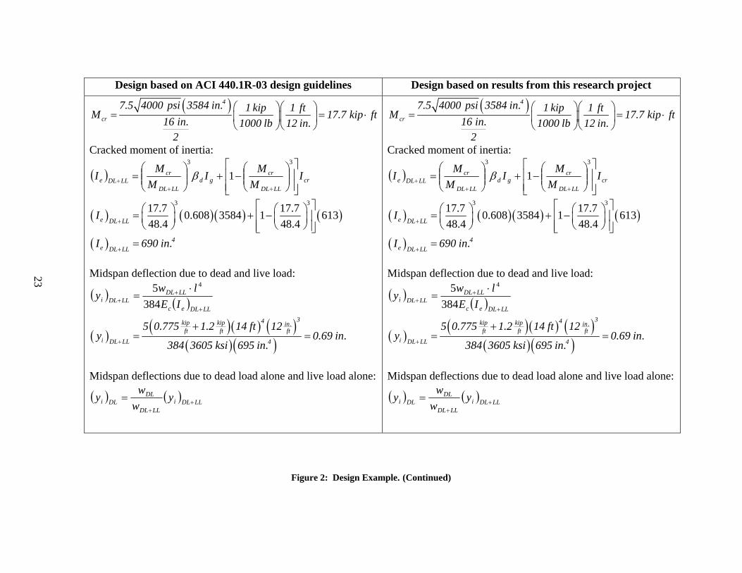
( )4
cr
7.5 4000 psi 3584 in. 1 kip 1 ftM 17.7 kip ft16 in. 1000 lb 12 in.2
⎛ ⎞⎛ ⎞= = ⋅⎜ ⎟⎜ ⎟
⎝ ⎠⎝ ⎠
Cracked moment of inertia:
( ) crLLDL
crgd
LLDL
crLLDLe I
MMI
MMI
⎥⎥⎦
⎤
⎢⎢⎣
⎡⎟⎟⎠
⎞⎜⎜⎝
⎛−+⎟⎟
⎠
⎞⎜⎜⎝
⎛=
+++
33
1β
( ) ( )( ) ( )3 317.7 17.70.608 3584 1 613
48.4 48.4e DL LLI
+
⎡ ⎤⎛ ⎞ ⎛ ⎞= + −⎢ ⎥⎜ ⎟ ⎜ ⎟⎝ ⎠ ⎝ ⎠⎢ ⎥⎣ ⎦
( ) 4e DL LL
I 690 in.+
= Midspan deflection due to dead and live load:
( ) ( ) LLDLec
LLDLLLDLi IE
lwy
+
++
⋅=
3845 4
( ) ( )( ) ( )( )( )
34kip kip in.ft ft ft
i DL LL 4
5 0.775 1.2 14 ft 12y 0.69 in.
384 3605 ksi 695 in.+
+= =
Midspan deflections due to dead load alone and live load alone:
( ) ( ) LLDLiLLDL
DLDLi y
ww
y ++
=
Figure 2: Design Example. (Continued)

24
Design based on ACI 440.1R-03 design guidelines Design based on results from this research project
( ) ( )kipft
i kip kipDLft ft
0.775y 0.69 in. 0.27 in.
0.775 1.2= =
+
( ) ( ) LLDLiLLDL
LLLLi y
wwy +
+
=
( ) ( )kipft
i kip kipLLft ft
1.2y 0.69 in. 0.42 in.
0.775 1.2= =
+
Allowable instantaneous live load deflection:
( )360
ly LLi =
( )( )inft14 ft 12
0.42 in. 0.47 in.360
< = ∴ O.K. Long-term deflection: ξ = 1.25 (ACI 318 for a duration of six months)
ξλ 60.0= ( ) 75.025.160.0 ==λ
Compute six-month deflection and compare to allowable:
( ) ( )DLiLLiLT yyy λ+=
( ) ( )LTy 0.42 in. 0.75 0.27 in. 0.62 in.= + =
( ) ( )kipft
i kip kipDLft ft
0.775y 0.69 in. 0.27 in.
0.775 1.2= =
+
( ) ( ) LLDLiLLDL
LLLLi y
wwy +
+
=
( ) ( )kipft
i kip kipLLft ft
1.2y 0.69 in. 0.42 in.
0.775 1.2= =
+
Allowable instantaneous live load deflection:
( )360
ly LLi =
( )( )inft14 ft 12
0.42 in. 0.47 in.360
< = ∴ O.K.
Long-term deflection due to dead load: Compute initial top fiber strain and curvature at midspan. Area of transformed section in compression:
( )( )( ) 2cA bkd 10.5 in. 0.221 13.75 in. 31.9 in.= = =
First moment of area of transformed section in compression about top surface:
( ) ( ) ( )( ) 223
c
0.221 13.75 in.kdB b 10.5 in. 48.5 in.
2 2⎡ ⎤⎣ ⎦= = =
Figure 2: Design Example. (Continued)

25
Design based on ACI 440.1R-03 design guidelines Design based on results from this research project Allowable long-term deflection:
240lyLT ≤
( )( )in.ft14 ft 12
0.62 in. 0.70 in.240
< = ∴ OK
Moment of inertia of transformed section in compression about top surface:
( ) ( )212
23 kdbkdbIc +=
( ) ( )( ) ( ) ( )( )3 3
c
0.221 13.75 in. 0.221 13.75 in.I 10.5 in. 10.5 in.
12 4⎡ ⎤ ⎡ ⎤⎣ ⎦ ⎣ ⎦= +
4cI 98.3 in.=
( )3
'
1 kcc
cc ddABAA
−−
+=
( )( )( )
3 2' 2 2c 0.221
3
48.5 in. 13.75 in. 31.9 in.A 31.9 in. 1.27 in.
13.75 in. 1−
= + =−
( )3
'
1 kcc
cc ddBIBB−
−+=
( )( )( )
4 3' 3 3c 0.221
3
98.3 in. 13.75 in. 48.5 in.B 48.5 in. 3.86 in.
13.75 in. 1−
= + =−
Moment due to dead load: 2
8DL
DLw lM ⋅
=
Figure 2: Design Example. (Continued)
26
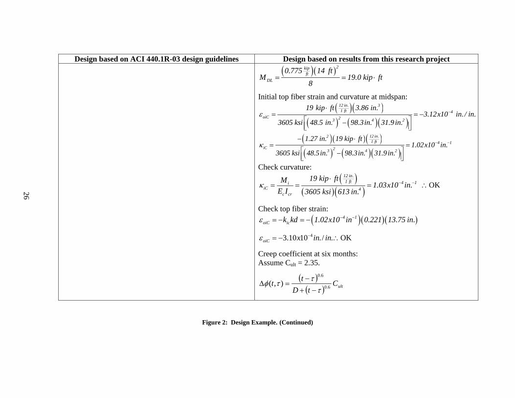
Design based on ACI 440.1R-03 design guidelines Design based on results from this research project ( )( )2kip
ftDL
0.775 14 ftM 19.0 kip ft
8= = ⋅
Initial top fiber strain and curvature at midspan: ( )( )
( ) ( )( )
12 in. 31 ft 4
oiC 23 4 2
19 kip ft 3.86 in.3.12x10 in. / in.
3605 ksi 48.5 in. 98.3in. 31.9 in.ε −
⋅= = −
⎡ ⎤−⎢ ⎥⎣ ⎦
( )( )( )( ) ( )( )
12 in.21 ft 4 1
iC 23 4 2
1.27 in. 19 kip ft1.02x10 in.
3605 ksi 48.5in. 98.3in. 31.9 in.κ − −
− ⋅= =
⎡ ⎤−⎢ ⎥⎣ ⎦
Check curvature: ( )
( )( )12 in.1 ft 4 1i
iC 4c cr
19 kip ftM 1.03x10 in.E I 3605 ksi 613 in.
κ − −⋅
= = = ∴OK
Check top fiber strain: ( )( )( )4 1
oiC ick kd 1.02x10 in 0.221 13.75 in.ε − −= − = −
43.10 10 ./ .oiC x in inε −= − ∴OK
Creep coefficient at six months: Assume Cult = 2.35.
( )( ) ultCtD
tt 6.0
6.0
),(τ
ττφ−+
−=Δ
Figure 2: Design Example. (Continued)

27
Design based on ACI 440.1R-03 design guidelines Design based on results from this research project ( )
( )( ) 60.135.2
141801014180)14,180( 6.0
6.0
=−+
−=Δφ
Choose an aging coefficient χ = 0.8, as recommended by Gilbert and Mickleborough: Shrinkage strain at six months: Assume the beam was cured for 7 days.
( ) ( )ultshtsh tt εε+
=35
Assume (εsh)ult = -730x10-6
( ) ( )( ) ( )6 4
180 7
180 7730 10 6.07 10 ./ .
35 180 7sh x x in inε − −−
−= − = −
+ −
Obtain an equivalent imaginary creep loss of prestressing force at six months. As explained in the creep test results section, the creep strain can be assumed to be independent of stress. Thus, for a beam with a distributed load, the creep strain will be assumed to be constant over the full length of the 14-ft span. The creep strain at six months of 234x10-6 inch/inch from specimen V1-5-b of the creep test will be used.
Figure 2: Design Example. (Continued)

28
Design based on ACI 440.1R-03 design guidelines Design based on results from this research project Thus, the equivalent imaginary creep loss of prestressing
force is: ( )( )6 2in.
c1 f f in.F P E A 234x10 6279 ksi 2.60 in. 3.82 kipΔ ε −= = − = − = −
Age-adjusted effective modulus:
),(1),(
τφχτ
tE
tE ce Δ+
=
( )( )e3605 ksiE ( t , ) 1591 ksi
1 0.8 1.60τ = =
+
Total restraining forces at midspan:
( )[ ] ∑=
+++Δ−=−m
jjcshiCcoiCce FABAEN
1εκεφδ
( )( ) ( )( )2 4 3 4 1c oiC c iCA B 31.9 in. 3.12x10 48.5 in. 1.02x10 in.ε κ − − −+ = − +
23 .100.5 inxBA iCcoiCc−−=+ κε
( ) ( ) ( )( )3 2 4 2c oiC c iC sh cA B A 1.6 5.0x10 in. 6.07 x10 31.9 in.Δφ ε κ ε − −+ + = − + −
( ) 2c oiC c iC sh cA B A 0.0273 in.Δφ ε κ ε+ + = −
( )2N 1579 ksi 0.0273 in. 3.82 kipδ− = − − −
N 39.3 kipδ− =
Figure 2: Design Example. (Continued)

29
Design based on ACI 440.1R-03 design guidelines Design based on results from this research project ( )[ ] ∑
=
+++Δ−=−m
jjjcshicoice dFBIBEM
1εκεφδ
( )( ) ( )( )3 4 4 4 1c oiC c iCB I 48.5 in. 3.12x10 98.3 in. 1.02x10 in.ε κ − − −+ = − +
33 .1011.5 inxIB iCcoiCc−−=+ κε
( ) ( ) ( ) ( )3 3 4 3c oiC c iC sh cB I B 1.6 5.11x10 in. 6.07 x10 48.5 in.Δφ ε κ ε − −+ + = − + −
( ) 3c oiC c iC sh cB I B 0.0376 in.Δφ ε κ ε+ + = −
( )( )( )1 ft12 in.Fd 3.82 kip 13.75 in. 4.38 kip ft= − = − ⋅
( )( )1 ft312 in.M 1579 ksi 0.0376 in. 4.38 kip ftδ− = − − − ⋅
M 0.57 kip ftδ− = ⋅ Properties of age-adjusted transformed section: Area of age-adjusted transformed section:
ffee AnbkdA +=
ffe
e
E 6279 ksin 3.98E 1579 ksi
= = =
( )( )( ) ( )2 2eA 10.5 in. 0.221 13.75 in. 3.98 2.6 in. 42.2 in.= + =
Figure 2: Design Example. (Continued)

30
Design based on ACI 440.1R-03 design guidelines Design based on results from this research project First moment of area of age-adjusted transformed section
about top of surface: ( ) dAnkdbB ffee +=
2
2
( ) ( ) ( ) ( )( )2
2 3e
0.221 13.75 in.B 10.5 in. 3.98 2.6 in. 13.75 in. 191 in.
2⎡ ⎤⎣ ⎦= + =
Moment of inertia of transformed section in compression about top of surface:
( ) ( ) 223
212dAnkdbkdbI ffee ++=
( ) ( )( ) ( ) ( ) ( )3 3
e
0.221 13.75 in. 0.221 13.75 in.I 10.5 in. 10.5 in.
12 4⎡ ⎤ ⎡ ⎤⎣ ⎦ ⎣ ⎦= +
( )( )223.98 2.6 in. 13.75 in.+
4eI 2054 in.=
( )3
'
1 kee
ee ddAB
AA−
−+=
( )( )( )
3 2' 2 2e 0.221
3
191 in. 13.75 in. 42.2 in.A 42.2 in. 11.6 in.
13.75 in. 1−
= + =−
Figure 2: Design Example. (Continued)

31
Design based on ACI 440.1R-03 design guidelines Design based on results from this research project
( )3
'
1 kee
ee ddBI
BB−
−+=
( )( )( )
4 3' 3 3e 0.221
3
2054 in. 13.75 in. 191 in.B 191 in. 146 in.
13.75 in. 1−
= + =−
Time-dependent increments of curvature and top surface strain at midspan:
( )eeee
eeoC AIBE
NIMB−−
=Δ 2
' δδε
( )( )( ) ( )( )( ) ( )( )
12 in. 3 41 ft
oC 23 4 2
0.57 kip ft 146 in. 39.4 kip 2054 in.
1579 ksi 191in. 2054 in. 42.2 in.Δε
− ⋅ − −=
⎡ ⎤−⎢ ⎥⎣ ⎦31001.1 −−=Δ xoCε
( )eeee
eeC AIBE
MANB−
−=Δ 2
'δδκ
( )( ) ( )( )( )( ) ( )( )
12 in.3 21 ft
C 23 2 2
191 in. 39.4 kip 11.6 in. 0.57 kip ft
1579 ksi 191in. 2054 in. 42.2 in.Δκ
− − − ⋅=
⎡ ⎤−⎢ ⎥⎣ ⎦15 .1039.9 −−=Δ inxCκ
./.1031.1 3 ininxoCoiCoC−−=Δ+= εεε
Figure 2: Design Example. (Continued)
32
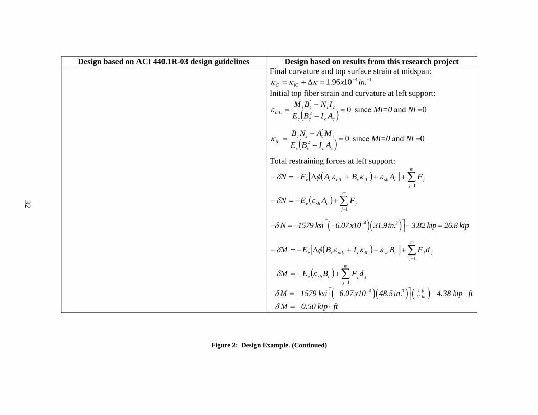
Design based on ACI 440.1R-03 design guidelines Design based on results from this research project Final curvature and top surface strain at midspan:
14 .1096.1 −−=Δ+= inxiCC κκκ Initial top fiber strain and curvature at left support:
( ) 02
'
=−−
=cccc
cicioiL AIBE
INBMε since Mi=0 and Ni =0
( ) 02
'
=−
−=
cccc
iciciL AIBE
MANBκ since Mi=0 and Ni =0
Total restraining forces at left support:
( )[ ] ∑=
+++Δ−=−m
jjcshiLcoiLce FABAEN
1εκεφδ
( ) ∑=
+−=−m
jjcshe FAEN
1εδ
( )( )4 2N 1579 ksi 6.07x10 31.9in. 3.82 kip 26.8 kipδ −⎡ ⎤− = − − − =⎣ ⎦
( )[ ] ∑=
+++Δ−=−m
jjjcshiLcoiLce dFBIBEM
1εκεφδ
( ) ∑=
+−=−m
jjjcshe dFBEM
1εδ
( )( ) ( )1 ft4 312 in.M 1579 ksi 6.07 x10 48.5 in. 4.38 kip ftδ −⎡ ⎤− = − − − ⋅⎣ ⎦
M 0.50 kip ftδ− = − ⋅
Figure 2: Design Example. (Continued)
33
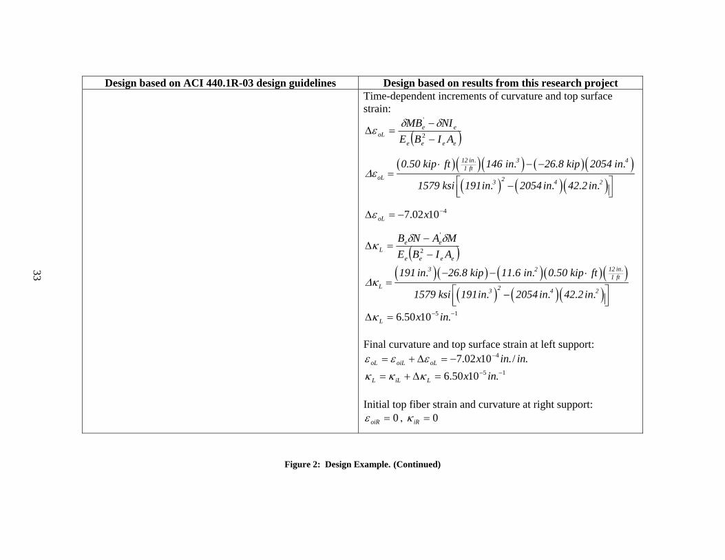
Design based on ACI 440.1R-03 design guidelines Design based on results from this research project Time-dependent increments of curvature and top surface
strain:
( )eeee
eeoL AIBE
NIMB−−
=Δ 2
' δδε
( )( )( ) ( )( )( ) ( )( )
12 in. 3 41 ft
oL 23 4 2
0.50 kip ft 146 in. 26.8 kip 2054 in.
1579 ksi 191in. 2054 in. 42.2 in.Δε
⋅ − −=
⎡ ⎤−⎢ ⎥⎣ ⎦
41002.7 −−=Δ xoLε
( )eeee
eeL AIBE
MANB−
−=Δ 2
'δδκ
( )( ) ( )( )( )( ) ( )( )
12 in.3 21 ft
L 23 4 2
191 in. 26.8 kip 11.6 in. 0.50 kip ft
1579 ksi 191in. 2054 in. 42.2 in.Δκ
− − ⋅=
⎡ ⎤−⎢ ⎥⎣ ⎦
15 .1050.6 −−=Δ inxLκ Final curvature and top surface strain at left support:
./.1002.7 4 ininxoLoiLoL−−=Δ+= εεε
15 .1050.6 −−=Δ+= inxLiLL κκκ Initial top fiber strain and curvature at right support:
0=oiRε , 0=iRκ
Figure 2: Design Example. (Continued)

34
Design based on ACI 440.1R-03 design guidelines Design based on results from this research project Final curvature and top surface strain at left support:
./.1002.7 4 ininxoR−−=ε
15 .1050.6 −−= inxRκ Compute midspan deflection at six months due to dead load:
( ) ( )RCLDLLTLy κκκ ++= 1096
2
( )( )( ) ( )( )
212 in.1 ft 5 1 4 5 1
LT DL
14 fty 6.50x10 in. 10 1.02x10 6.50x10 in.
96− − − − −
⎡ ⎤⎣ ⎦= + +
( )LT DLy 0.61 in.=
Total six-month deflection at midspan:
( ) ( )DLLTLLiLT yyy +=
LTy 0.41 in. 0.61 in. 1.03 in.= + = Allowable long-term deflection:
240lyLT ≤
( )( )in.ft14 ft 12
1.03 in. 0.70 in.240
> = ∴ N.G.
Before redesigning the section, check the maximum crack
width.
Figure 2: Design Example. (Continued)

35
Design based on ACI 440.1R-03 design guidelines Design based on results from this research project 6. Check the maximum crack width. Compute the stress level in the FRP bars under dead load plus live load (service conditions):
⎟⎠⎞
⎜⎝⎛ −
= +
31 kdA
Mff
LLDLf
( )f
2
12 in.48.4 kip ft1 ft
f 17.5 ksi0.2212.60 in. 13.75 in. 1
3
⎛ ⎞⋅ ⎜ ⎟
⎝ ⎠= =⎛ ⎞−⎜ ⎟⎝ ⎠
Find the effective tension area of concrete:
kddkdh
−−
=β
( )( )
16 in. 0.221 13.75 in.1.21
13.75 in. 0.221 13.75 in.β
−= =
−
=cd cover + stirrup size bd21
+
( )c1d 1.5 in. 0.375 0.743 in. 2.25 in.2
= + + =
( )2 h d bA
No.bars−
=
( )( ) 22 16 in. 13.75 in. 10.5 in.A 7.86 in.
6−
= =
6. Check the maximum crack width. Compute the stress level in the FRP bars under dead load plus live load (service conditions):
⎟⎠⎞
⎜⎝⎛ −
= +
31 kdA
Mff
LLDLf
( )f
2
12 in.48.4 kip ft1 ft
f 17.5 ksi0.2212.60 in. 13.75 in. 1
3
⎛ ⎞⋅ ⎜ ⎟
⎝ ⎠= =⎛ ⎞−⎜ ⎟⎝ ⎠
Find the effective tension area of concrete:
kddkdh
−−
=β
( )( )
16 in. 0.221 13.75 in.1.21
13.75 in. 0.221 13.75 in.β
−= =
−
=cd cover + stirrup size bd21
+
( )c1d 1.5 in. 0.375 0.743 in. 2.25 in.2
= + + =
( )2 h d bA
No.bars−
=
( )( ) 22 16 in. 13.75 in. 10.5 in.A 7.86 in.
6−
= =
Figure 2: Design Example. (Continued)

36
Design based on ACI 440.1R-03 design guidelines Design based on results from this research project Compute the maximum crack width using ACI 440.1R-03 Equation 8-9b:
3076.0 AdfEE
w cff
sβ=
( ) ( ) ( )( )2329000w 0.076 1.21 17.5 ksi 2.25 in. 7.86 in.6279
=
w 19 mils 20 mils= < ∴ OK Compute the maximum crack width using ACI 440.1R-03 Equation 8-9c, using the recommended value of kb = 1.2:
32200 AdfkE
w cfbf
β=
( )( )( ) ( )( )232200w 1.21 1.2 17.5 ksi 2.25 in. 7.86 in.6279
=
23 20w mils mils= > ∴ N.G.
Compute the maximum crack width using Equation 81 from this research:
3max 09.0 AdfW cf ⋅⋅= β
( ) ( ) ( )( )23max
29000W 0.09 1.21 17.5 ksi 2.25 in. 7.86 in.6279
=
maxW 23 mils 20 mils= > ∴ N.G. Redesign the beam.
5a. Check the short-and long-term deflections of the beam. The beam is adequate for short-term and long-term deflections.
5a. Check the short-and long-term deflections of the beam. Try h = 19 inches.
bdAf
f =ρ
2
f fb2.60 in. 0.0148 1.4 0.0152 0.7
10.5 in.(16.75 in.)ρ ρ φ= = < = ∴ =
Figure 2: Design Example. (Continued)
37
Design based on ACI 440.1R-03 design guidelines Design based on results from this research project Moment capacity:
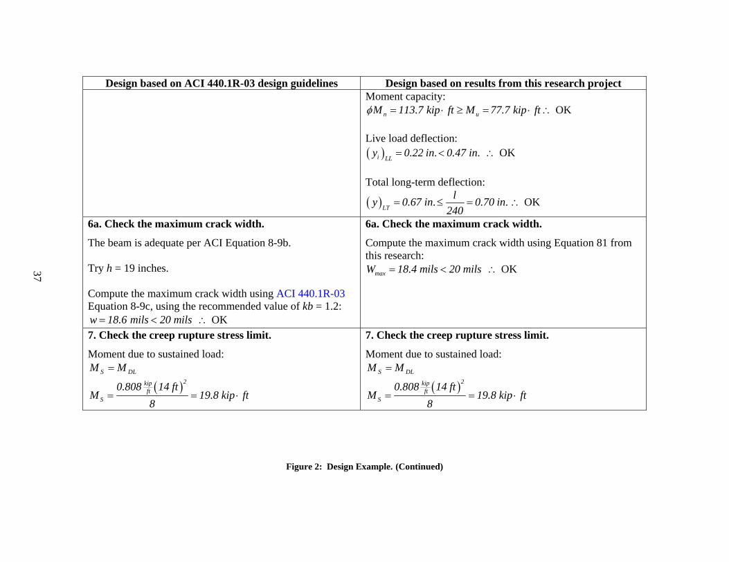
n uM 113.7 kip ft M 77.7 kip ftφ = ⋅ ≥ = ⋅ ∴ OK Live load deflection: ( )i LL
y 0.22 in. 0.47 in.= < ∴ OK Total long-term deflection:
( )LT
ly 0.67 in. 0.70 in.240
= ≤ = ∴ OK
6a. Check the maximum crack width.
The beam is adequate per ACI Equation 8-9b. Try h = 19 inches. Compute the maximum crack width using ACI 440.1R-03 Equation 8-9c, using the recommended value of kb = 1.2: w 18.6 mils 20 mils= < ∴ OK
6a. Check the maximum crack width.
Compute the maximum crack width using Equation 81 from this research:
maxW 18.4 mils 20 mils= < ∴ OK
7. Check the creep rupture stress limit.
Moment due to sustained load: DLS MM =
( )2kipft
S
0.808 14 ftM 19.8 kip ft
8= = ⋅
7. Check the creep rupture stress limit.
Moment due to sustained load: DLS MM =
( )2kipft
S
0.808 14 ftM 19.8 kip ft
8= = ⋅
Figure 2: Design Example. (Continued)

38
Design based on ACI 440.1R-03 design guidelines Design based on results from this research project Sustained stress in the FRP bars:
⎟⎠⎞
⎜⎝⎛ −
=
31
, kdA
Mf
f
SSf
( )f
2
12 in.19.8 kip ft1 ft
f 5.85 ksi0.2032.6 in. 16.75 in. 1
3
⎛ ⎞⋅ ⎜ ⎟
⎝ ⎠= =⎛ ⎞−⎜ ⎟⎝ ⎠
Check the stress limit for GFRP bars: fuSf ff 20.0, ≤
( )5.85 ksi 0.20 62 ksi 12.4 ksi≤ = ∴ O.K.
Sustained stress in the FRP bars:
⎟⎠⎞
⎜⎝⎛ −
=
31
, kdA
Mf
f
SSf
( )f
2
12 in.19.8 kip ft1 ft
f 5.85 ksi0.2032.6 in. 16.75 in. 1
3
⎛ ⎞⋅ ⎜ ⎟
⎝ ⎠= =⎛ ⎞−⎜ ⎟⎝ ⎠
Check the stress limit for GFRP bars: fuSf ff 20.0, ≤
( )5.85 ksi 0.20 62 ksi 12.4 ksi≤ = ∴ O.K. 8. Compute the basic development length.
Use ACI Equation 11-7: ( )( )b fu
bf
d f 0.743 in. 62000 psil 17 in.
2700 2700= = =
8. Compute the basic development length.
Use Equation 90 from this research: ( )( )b u ,ave
bf
0.743 in. 96000 psid fl 26.4 in.
2700 2700= = =
9. Compute additional deflections due to cyclic loading.
ACI 440.1R-03 does not account for deflections due to cyclic loading.
9. Compute additional deflections due to cyclic loading.
Assume the cyclic loading will be due to live load alone. Thus, use the slope of Equation 84 from this research, and use the initial deflection due to dead load and live load.
Figure 2: Design Example. (Continued)

39
Design based on ACI 440.1R-03 design guidelines Design based on results from this research project
Initial deflection due to dead load and live load:
( ) ( ) LLDLec
LLDLLLDLi IE
lwy
+
++
⋅=
3845 4
( ) ( )( ) ( )( )( )
34kip kip in.ft ft ft
i DL LL 4
5 0.808 1.2 14 ft 12y 0.15 in. 0.22 in.
384 3605 ksi 1299 in.+
+= = +
( )i DL LLy 0.37 in.
+=
Lower bound beam defection due to 2 million cycles of application of live load: y 0.0046 in.ln( n ) 0.37 in.= + y 0.0046 in.ln( 2000000 ) 0.37 in. 0.47 in.= + =
Figure 2: Design Example. (Continued)
40
As a result of this review, the researchers proposed the following changes to the
ACI 440.1R-03 design and construction guidelines. A reevaluation of the environmental
reduction factors is proposed, since this research showed that they may not be
conservative. Equation 2, presented earlier, is proposed to replace Equation 8, 9a in the
ACI 440.1R-03 design and construction guide (2003). This research also proposes that
the deflections of GFRP-reinforced concrete elements induced by cyclic loading also be
accounted for in the ACI 440.1R-03 design and construction guidelines. Creep should
be accounted for as shown in Report 9-1520-3 (Trejo et al. 2003). Equation 9 of this
report is proposed to replace Equation 11-7 of the ACI 440.1R-03 design and
construction guidelines. Finally, the minimum cover of 1 bar diameter recommended by
the ACI 440.1R-03 design and construction guidelines cannot be verified for adequacy
using this research. However, this research showed that a cover of 1.33 bar diameters
has been shown by this research to have no cracking problems due to thermal expansion.

41
III. PROPOSED REVISIONS TO THE AASHTO LRFD BRIDGE
DESIGN SPECIFICATIONS
This section presents a review of the 1998 AASHTO LRFD bridge design
specifications (1998) and recommends changes based on the results of this and other
research related to the use of non-prestressed GFRP bars to reinforce concrete structures.
This section presents a brief introduction followed by a description of the AASHTO
sections that may need to be modified to include the design of concrete elements
reinforced with FRP bars. The sections of the AASHTO specifications that do not need
to be modified are not listed in this section.
The 1998 AASHTO LRFD bridge design specifications do not include
recommendations for the design of concrete structures reinforced with GFRP bars.
Because the results obtained by this research and by the studies referenced are limited to
the conditions and exposures evaluated in this research, extreme care should be taken
when designing GFRP-reinforced concrete elements that will be subjected to different
conditions. It should be noted that these recommendations are proposed based on the
research to date and in most cases more work is needed before implementing such
modifications. A review of the applicable sections is presented next. Note that the
section numbers listed below are the section numbers from the 1998 AASHTO LRFD
bridge design specifications.
PROPOSED REVISIONS
1. Add to Section 1.3.3 Ductility
This section of the code requires the bridge to develop significant and visible
inelastic deformations at the strength and extreme event limit states. Since GFRP bars
exhibit linearly elastic behavior up to failure, GFRP-reinforced concrete elements do not
exhibit significant ductility. Naaman and Jeong (1995) indicated that although FRP-
reinforced concrete beams may deform considerably before failure, they elastically store
most of the energy imposed on them during loading. Thus, since inelastic deformations

42
are required by the code, either GFRP bars should not be used or GFRP bars should be
used in combination with other systems or materials to provide ductility. Alternatively,
the code may develop non-ductile behavior requirements for GFRP-reinforced concrete
elements.
2. Add to Section 2.5.2.1.1 Materials
The degradation of GFRP reinforcement should be accounted for in design. The
tensile strength of GFRP bars can degrade in the concrete. The durability of FRP-
reinforced concrete structures can be affected by several environmental factors such as:
acids, alkalis, high temperatures, ultraviolet radiation, organic solvents, and oxygen or
ozone (Bakht et al. 2000). The bond strength between GFRP bars and concrete can
degrade with time in high-temperature moist conditions.
3. Add to Section 3.10.1 General
The fact that FRP-reinforced concrete elements are non-ductile should be
considered when performing a seismic design.
4. Notice for Section 4.6.2 Approximate Methods of Analysis
This section may require modifications because FRP-reinforced concrete
elements with a given amount and distribution of reinforcement and a given geometry
have lower stiffness than steel-reinforced concrete elements having the same geometry
and amount and configuration of reinforcement.
5. Notice for Section 5 Concrete Structures
The ACI 440.1R-03 (2003) design and construction guidelines should be adopted
for this section. However, special care must be taken to ensure that these equations and
factors apply to the conditions at the actual structures’ location because it has been
determined that environmental conditions do affect the performance of GFRP
reinforcing bars. Special consideration should be given to the subsections addressed in
the following proposed revisions.

43
6. Add to Section 5.4 Material Properties
Consideration should be given in this section to the material properties of GFRP
bars such as tensile strength, accounting for environmental reduction factors, as already
discussed in the ACI 440.1R-03 design and construction guidelines, coefficient of
thermal expansion of the FRP bars, creep of FRP bars, deflections due to cyclic loading,
and deterioration of bond strength between GFRP bars and concrete. A description of the
durability and reactivity of fibers and resins to different environmental conditions given
in the Canadian Bridge Design code provisions for fiber-reinforced structures could be
included in this section (Bakht et al. 2000). A summary of the deleterious effects of
several environments on fibers and matrices as described by Bakht et al. (2000) is given
next:
• Water: Polymeric fibers and matrices absorb moisture. Moisture absorption
softens the polymers. There are not sufficient data for the rate of deterioration of
carbon and glass fibers.
• Weak acids: Bridges in industrialized areas may be exposed to weak acids from
acid rain and carbonization, with pH values between 4 and 7. Weak acids can
attack glass fibers and polyester matrices.
• Strong acids: Accidental spillage may cause strong acids to come in contact with
bridge components. Strong acids can attack glass fibers, aramid fibers, and
polyester and epoxy matrices.
• Weak alkalis: Concrete containing pozzolans can have pH values between 7 and
10. Weak alkalis such as these materials can attack glass fibers and polyester
matrices.
• Strong alkalis: Typical Portland cement concretes have pH values greater than 10
and can cause degradation of glass fibers. Strong alkalis can attack glass fibers,
aramid fibers, and polyester matrices.
• High temperatures: Carbon and glass fibers are resistant to high temperatures.
However, high temperatures adversely affect aramid fibers and polymeric
matrices.
44
• Ultraviolet radiation: Carbon and glass fibers are resistant to ultraviolet
radiation. However, ultraviolet radiation adversely affects aramid fibers and
polymeric matrices.
7. Move Section 5.4.4 Prestressing Steel to Section 5.4.5
8. Move Section 5.4.5 Posttensioning Anchorages and Couplers to Section 5.4.6
9. Move Section 5.4.6 Ducts to Section 5.4.7
10. Add Section 5.4.4 FRP Reinforcement
11. Add Section 5.4.4.1 General
The design tensile strength of GFRP bars should be taken from the ACI 440.1R-
03 design and construction guidelines as shown previously in Equation 1: *fuEfu fCf =
12. Add Section 5.4.4.2 Modulus of Elasticity
The modulus of elasticity of FRP bars should be the average value reported from
proper testing or by the manufacturer.
13. Add to Section 5.5.3.2 Reinforcing Bars
The results of the cyclic load tests conducted in this research indicate that the
flexural strength of GFRP-reinforced concrete beams show no significant degradation
after the application of 4 and 5 million cycles of an alternating load with a GFRP bar
stress range of 18.9 ksi. The fatigue capacity of FRP bars to be used in a bridge should
be validated by further tests.

45
14. Add Section 5.5.4.2.4 FRP Construction
The resistance factors recommended by the ACI 440.1R-03 design and
construction guidelines should be used in this section. The resistance factors for flexure
are:
φ = 0.50 for ρf ≤ ρfb
φ = fb
f
ρρ
2 for ρf < ρfb < 1.4ρfb (12)
φ = 0.70 for ρf ≥ 1.4ρfb
The resistance factor for shear should be the same as the factor used in the ACI
318 (2000) building code (φ = 0.85).
15. Add Section 5.7.3.2.5 FRP-Reinforced Concrete Elements
The equations for flexural resistance given in the ACI 440.1R-03 design and
construction guidelines should be used in this section. The reinforcement ratio ( fρ ) and
the balanced reinforcement ratio ( fbρ ) for GFRP-reinforced sections can be computed
with Equations 13 and 14, respectively:
bdAf
f =ρ (13)
fucuf
cuf
fu
cfb fE
Eff
+=
εε
βρ'
185.0 (14)
where,
Af = Area of FRP reinforcement (inch2),
a = Depth of equivalent rectangular stress block (inch),
b = Width of section (inch),
d = Effective depth of the section (inch),
εcu = Ultimate strain in concrete,
β1 = Factor taken as 0.85 for values of f’c up to and including 4 ksi. Above 4 ksi,
the factored is reduced linearly at a rate of 0.05 for each 1 ksi in excess of 4
ksi, but should not be smaller than 0.65,
46
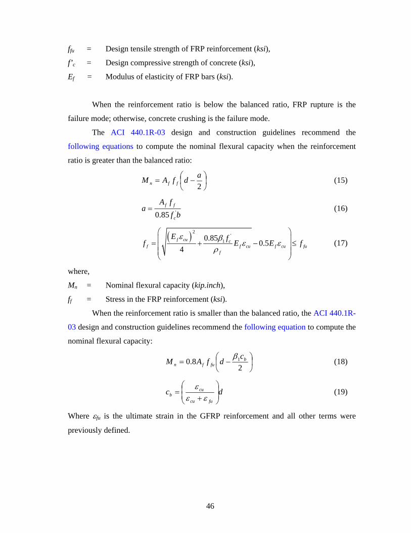
ffu = Design tensile strength of FRP reinforcement (ksi),
f’c = Design compressive strength of concrete (ksi),
Ef = Modulus of elasticity of FRP bars (ksi).
When the reinforcement ratio is below the balanced ratio, FRP rupture is the
failure mode; otherwise, concrete crushing is the failure mode.
The ACI 440.1R-03 design and construction guidelines recommend the
following equations to compute the nominal flexural capacity when the reinforcement
ratio is greater than the balanced ratio:
⎟⎠⎞
⎜⎝⎛ −=
2adfAM ffn (15)
bffA
ac
ff'85.0
= (16)
( ) 2'
10.85 0.54
f cu cf f cu f cu fu
f
E ff E E fε β ε ε
ρ
⎛ ⎞⎜ ⎟= + − ≤⎜ ⎟⎜ ⎟⎝ ⎠
(17)
where,
Mn = Nominal flexural capacity (kip.inch),
ff = Stress in the FRP reinforcement (ksi).
When the reinforcement ratio is smaller than the balanced ratio, the ACI 440.1R-
03 design and construction guidelines recommend the following equation to compute the
nominal flexural capacity:
⎟⎠⎞
⎜⎝⎛ −=
28.0 1 b
fufnc
dfAMβ
(18)
dcfucu
cub ⎟
⎟⎠
⎞⎜⎜⎝
⎛
+=
εεε
(19)
Where εfu is the ultimate strain in the GFRP reinforcement and all other terms were
previously defined.
47
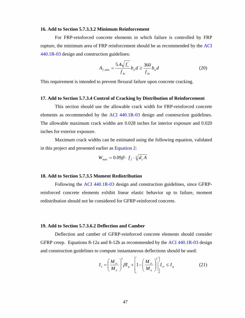
16. Add to Section 5.7.3.3.2 Minimum Reinforcement
For FRP-reinforced concrete elements in which failure is controlled by FRP
rupture, the minimum area of FRP reinforcement should be as recommended by the ACI
440.1R-03 design and construction guidelines:
dbf
dbf
fA w
fuw
fu
cf
3604.5 '
min, ≥= (20)
This requirement is intended to prevent flexural failure upon concrete cracking.
17. Add to Section 5.7.3.4 Control of Cracking by Distribution of Reinforcement
This section should use the allowable crack width for FRP-reinforced concrete
elements as recommended by the ACI 440.1R-03 design and construction guidelines.
The allowable maximum crack widths are 0.028 inches for interior exposure and 0.020
inches for exterior exposure.
Maximum crack widths can be estimated using the following equation, validated
in this project and presented earlier as Equation 2:
3max 09.0 AdfW cf ⋅⋅= β
18. Add to Section 5.7.3.5 Moment Redistribution
Following the ACI 440.1R-03 design and construction guidelines, since GFRP-
reinforced concrete elements exhibit linear elastic behavior up to failure, moment
redistribution should not be considered for GFRP-reinforced concrete.
19. Add to Section 5.7.3.6.2 Deflection and Camber
Deflection and camber of GFRP-reinforced concrete elements should consider
GFRP creep. Equations 8-12a and 8-12b as recommended by the ACI 440.1R-03 design
and construction guidelines to compute instantaneous deflections should be used:
gcra
crg
a
cre II
MMI
MMI ≤
⎥⎥⎦
⎤
⎢⎢⎣
⎡⎟⎟⎠
⎞⎜⎜⎝
⎛−+⎟⎟
⎠
⎞⎜⎜⎝
⎛=
33
1β (21)

48
⎟⎟⎠
⎞⎜⎜⎝
⎛+= 1
s
f
EE
αβ (22)
where,
Icr = cracked moment of inertia of the section (inch4),
Ig = Gross moment of inertia of the section (inch4),
and all other terms have been defined previously.
The long-term deflections can be computed using Equation 8-14, provided by the
ACI 440.1R-03 design and construction guidelines and shown previously as Equation 6:
( ) ( )susishcp Δ=Δ + ξ6.0
Alternatively, the change in curvature due to long-term loading can be computed
using the following equation, shown earlier as Equation 7:
( )eeee
ee
IABEMANB
−
−=Δ 2
'δδκ
and the long-term deflections can be computed by substituting Equation 7 into
Equation 8:
( )BCACLy κκκ ++= 1096
2
Cyclic loading of concrete beam tests shows that deflections due to cyclic
loading can increase by 78 percent due to cyclic loading and should be included in the
computation of deflections due to live load.
The slope of Equation 5 can be used to compute the lower bound deflection
increments due to the application of cyclic load:
0858.0)ln(0046.0 += ny

49
20. Add to Section 5.8.2.5 Minimum Transverse Reinforcement
The requirements for minimum transverse reinforcement provided by the ACI
440.1R-03 design and construction guidelines should be adopted in this section. The
minimum transverse reinforcement for FRP-reinforced concrete sections is:
fv
wfv f
sbA
50min, = (23)
where,
Afv,min = Minimum area of transverse FRP reinforcement (inch2),
bw = Width of section (inch),
s = Spacing of stirrups (inch),
ffv = Stress level in the FRP shear reinforcement at ultimate (ksi).
According to the ACI 440.1R-03 design and construction guidelines, the stress
level in the FRP shear reinforcement at ultimate should be limited to the following value
to avoid failure at the bent portion of the FRP stirrup:
fbffv fEf ≤= 002.0 (24)
where ffb is the strength of a bent portion of an FRP stirrup (ksi).
21. Add to Section 5.8.3.3 Nominal Shear Resistance
The neutral axis depth of cracked FRP-reinforced concrete sections is smaller
than that for steel-reinforced concrete elements due to the lower stiffness of FRP bars
when compared to steel bars (ACI 2000). Thus, the contribution to shear strength by
aggregate interlock, dowel action, and shear of compressed concrete are lower for FRP-
reinforced concrete members than for steel-reinforced concrete members. This section
should adopt the recommendations of the ACI 440.1R-03 design and construction
guidelines for shear design of FRP-reinforced concrete members.
The ACI 440.1R-03 design and construction guide recommendations for the
shear force taken by the concrete should be used:
cc
fffc V
fE
V '1
, 90βρ
= (25)

50
where the terms are as defined before and Vc is the nominal shear force provided by the
concrete for steel-reinforced concrete members as given in the ACI 318 code (2000).
The value of Vc,f should not be larger than Vc.
The required spacing and area of shear reinforcement when stirrups are used
perpendicular to the member are:
( )df
VVs
A
fv
fcufv
⋅
−=
φφ , (26)
where the terms have been defined before and,
Afv = Area of shear reinforcement (inch2),
Vu = Factored shear force at section (kips).
22. Add to Section 5.10.2.1 Standard Hooks
The recommendation of ACI 440.1R-03 design and construction guidelines for a
minimum tail length of 12 bar diameters should be used in this section.
23. Add to Section 5.10.2.3 Minimum Bend Diameters
The minimum ratio of radius of bend to bar diameter of three for FRP stirrups, as
recommended by the ACI 440.1R-03 design and construction guidelines, should be
considered in FRP-reinforced concrete elements.
24. Add to Section 5.10.7 Transverse Reinforcement for Flexural Members
A maximum spacing for transverse reinforcement of d/2 or 24 inches, as
recommended by the ACI 440.1R-03 design and construction guidelines, should be
considered in this section.
25. Add to Section 5.10.8 Shrinkage and Temperature Reinforcement
The ACI 440.1R-03 design and construction guidelines recommended minimum
reinforcement ratio for temperature and shrinkage ρf,ts should be used in this section (but
need not be more than 0.00036):

51
0014.0000,600018.0, ≥=f
s
futsf E
Ef
ρ (27)
26. Notice for Section 5.10.11 Provisions for Seismic Design
Since GFRP reinforcement is non-ductile, provisions should be taken in the
design of GFRP-reinforced concrete elements where ductility is required.
27. Add to Section 5.11.2.1.1 Tension Development Length
This research recommends that the basic development length of GFRP-reinforced
concrete elements be computed with the following equation, shown earlier as Equation
11:
2700
,aveubbf
fdl =
28. Add to Section 5.11.2.1.2 Modification Factors that Increase ld
The ACI 440.1R-03 design and construction guidelines recommend a
modification factor of 1.3 for top bars to obtain the development length of an FRP bar
(ldf).
29. Add to Section 5.11.2.4.1 Basic Hook Development Length
The recommended development length for a bent bar provided by the ACI
440.1R-03 design and construction guidelines should be used in this section. The
development length for hooked bars is determined as follows:
bbhf fu'
c
dl 2000 for f 75,000 psif
= ⋅ ⋅ ≤
fu bbhf fu'
c
f dl for 75,000 psi f 150,000 psi37.5 f
= ⋅ ⋅ < < (28)
bbhf fu'
c
dl 4000 for f 150,000 psif
= ⋅ ⋅ ≥

52
The development length computed with Equation 28 should not be less than 12
db or 9 inches.
30. Add to Section 5.11.5.3.1 Lap Splices in Tension
There is limited research in this area. However, the ACI 440.1R-03 design and
construction guidelines recommend using values of 1.3 ldf for class A and 1.6 ldf for class
C splices (as defined by AASHTO). Since the value of 1.7 ld for class C splice
recommended by AASHTO is more conservative, it is advisable to use that value to
compute the development length of spliced FRP bars.
31. Add to Section 5.12 Durability
This section should give special consideration to the durability of GFRP
reinforcement. Refer to the new proposed section 5.4 Material Properties (recommended
by this research to be added to the AASHTO LRFD specifications) for a brief
description of environmental effects on GFRP bars. A summary of the deleterious effects
of several environments on fibers and matrices as described previously is repeated next:
• Water: Moisture absorption softens the polymers. There are not sufficient data
for the rate of deterioration of carbon and glass fibers.
• Weak acids: Weak acids can attack glass fibers and polyester matrices.
• Strong acids: Strong acids can attack glass fibers, aramid fibers, and polyester
and epoxy matrices.
• Weak alkalis: Weak alkalis can attack glass fibers and polyester matrices.
• Strong alkalis: Strong alkalis can attack glass fibers, aramid fibers, and polyester
matrices.
• High temperatures: Carbon and glass fibers are resistant to high temperatures.
Nevertheless, high temperatures adversely affect aramid fibers and polymeric
matrices.
53
• Ultraviolet radiation: Carbon and glass fibers are resistant to ultraviolet
radiation. However, ultraviolet radiation adversely affects aramid fibers and
polymeric matrices.
32. Add to Section 5.12.3 Concrete Cover
This section of the code specifies a minimum cover for exterior exposure of 2
inches. The recommended covers should consider the fact that a 1-inch cover for a
concrete deck with compressive strength of approximately 5.88 ksi and a 0.75-inch
diameter bar does not cause cracking due to thermal expansion. This implies that,
according to this research, a cover of 1.33 bar diameters is adequate to avoid cracking
due to thermal expansion for typical conditions encountered by bridge superstructures.
The 2-inch cover should be adequate for elements reinforced with 0.75-inch and smaller
diameter bars. The cover depth design of elements exposed to direct solar radiation
reinforced with bar diameters larger than 0.75 inch should be supported by tests.


55
IV. RECOMMENDED CONSTRUCTION GUIDELINES FOR THE
USE OF GFRP REINFORCEMENT
Construction using GFRP bars for reinforcement in concrete applications is
similar to construction using steel reinforcement with some modifications. Unlike
conventional steel reinforcement, GFRP reinforcing bars typically do not exhibit
individually clear markings that identify the manufacturer, bar type, or bar size. This is
lack of information typically a result of the manufacturing process. The ACI 440.1R-03
design and construction guidelines (2003) recommend that each producer label the solid
bars or shipping container/packaging, or both, with a symbol identifying the
manufacturer (XXX), type of fiber and nominal size (G for glass and number for
nominal bar size, e.g., G#4), strength grade of the bar (e.g., F90 to indicate that the
guaranteed tensile strength, *fuf , is greater than 90 ksi), and modulus grade (e.g., E5.5,
indicating that the modulus of elasticity is at least 5,500 ksi). Bar sizes are the same as
those listed in A615/A615M (2004), Standard Specification for Deformed and Plain
Billet-Steel Bars for Concrete Reinforcement. Although bending GFRP bars is possible,
due to the significant reduction in strength capacity caused by bending, most designs
specify straight bars. Straight GFRP bars are typically ordered identifying length,
guaranteed tensile strength, fiber type, diameter, and modulus of elasticity.
Significant differences between uncoated steel and GFRP reinforcing bars arise
in handling and storage. GFRP bars should be handled in such ways as to eliminate or
minimize surface damage, and storage conditions for GFRP bars should be controlled.
The ACI 440.1R-03 design and construction guidelines recommend the following for
GFRP bars:
• handle with work gloves;
• do not store on ground;
• exposure to high temperatures, ultraviolet rays, and chemical substances
should be avoided;
• clean GFRP bar surfaces by wiping the bars with solvents if contaminated;
• if necessary, use a spreader bar for lifting; and

56
• if necessary, cut bars with high-speed grinder or fine-blade saw (bars should
never be sheared).
The ACI design and construction guidelines provide further information and the reader
is directed to this document if further information is needed. These practices should
preserve the integrity of the GFRP bars.
In addition to handling and storage criteria for GFRP bars, guidance on the
placement of GFRP is needed. GFRP bars can be placed in similar manners as that of
steel reinforcing bars with the following additions and/or exceptions useful (ACI
440.1R-03 2003):
• requirements for chair placement should be included in project specifications;
• plastic or non-corrosive chairs are preferred;
• requirements for securing GFRP bars should be included in specifications to
prevent movement of GFRP bars during concrete placement;
• site bending of thermoset GFRP bars is not allowed; and
• lapping of bars is necessary, and information on length of lap should be
included in the specifications.
Figures 3 and 4 show GFRP rebar tying and chair placement and typical spacing for the
Sierrita de las Cruz bridge construction outside of Amarillo, Texas. It can be seen that
the GFRP bars were tied with coated wires (Figure 3) and typical chair spacing was
approximately 3 ft. Actual chair spacing is dependent on bar type, tie requirements, and
other parameters.
Figure 3. Tying of GFRP Bars. Figure 4. Chair Placement for GFRP
Reinforcement.

57
V. RECOMMENDED MAINTENANCE GUIDELINES FOR GFRP
REINFORCED CONCRETE STRUCTURES
Several concrete structures have been constructed with GFRP reinforcement.
Research results presented in Report 9-1520-3 (Trejo et al. 2003) indicate that GFRP bar
strength, cracking of GFRP-reinforced concrete, and fatigue (both static and dynamic)
could be critical issues associated with the use of GFRP bars in reinforced concrete
systems. The authors of this report have clearly presented issues associated with the use
of GFRP bars. In cases where GFRP bars have been used, personnel should evaluate the
structure on a periodic basis to ensure structural integrity. Limited research or field
work has been performed on maintenance and/or repair of GFRP-reinforced concrete
members, and significant additional research is needed. However, the following issues
should be evaluated and addressed as needed:
• cracking of the concrete;
• concrete spalling and delaminations;
• assessment of bar and member strength should be made, if tensile strength
deterioration is expected;
• member deflections.
This is not an all-inclusive list. Other issues could arise, and these issues should be
addressed using sound engineering judgment.
Maintenance of a GFRP-reinforced concrete member should include practices
that reduce exposure of the GFRP reinforcing bars to saturated concrete conditions or to
direct traffic. Maintenance should include sealing cracks and the concrete surface to
prevent water ingress, repairing spalling or voids, and repairing and/or rehabilitating
members as needed. Because previous research and field assessment of GFRP-
reinforced concrete elements is limited, the engineer in charge should make maintenance
and repair decisions as appropriate.

59
VI. SUMMARY
This report provided an overview of the design, construction, and maintenance of
bridge decks utilizing GFRP reinforcement. This overview is based on the observations
and findings from research project 9-1520. It should be noted that these results were
based on results from three different types of GFRP bars; each bar type from one
manufacturing lot. Thus, the general recommendations provided herein are made with
the assumption that the GFRP bars evaluated as part of research project 9-1520 were
representative GFRP bars. If this is the case, the following design statements can be
offered:
• Environmental reduction factors proposed by ACI may not be conservative.
• Cracking and deflection of GFRP-reinforced concrete are likely
underestimated by ACI.
• The development length of straight GFRP bars is likely not conservative.
• Thermal mismatch of concrete and GFRP bars should be evaluated but does
not seem to be as significant as originally believed.
GFRP reinforcing bars require special handling and storage procedures because
surface damage can lead to reduced strengths and accelerated tensile strength
deterioration of these bars. Bars should be stored such that exposure to high
temperatures, ultraviolet rays, and chemical substances is avoided.
Minimal field work and research have been performed and, as a result, only
limited recommendations can be made on the maintenance of GFRP-reinforced concrete
sections. As with most concrete systems, crack, spalls, and delaminations should be
repaired. Because this and other research has shown that GFRP bars deteriorate and can
fail under static and dynamic fatigue conditions, the engineer or responsible party(ies)
must evaluate the structure to determine capacity.

61
REFERENCES
ACI Committee 440.1R-03, Guide for the Design and Construction of Concrete with
FRP Bars, American Concrete Institute, Detroit, MI., 2003.
ACI Committee 318, “Building Code Requirements for Structural Concrete (ACI 318-
99) and Commentary (318R-99),” American Concrete Institute, Farmington
Hills, MI, April 2000, 391 pp.
AASHTO LRFD Bridge Design Specifications, 2nd
Edition. American Association of
State Highway and Transportation Officials, Washington, D.C., 1998.
Bakht, B., Al-Bazi, G., Banthia, N., Cheung, M., Erki, M. Faoro, M., Machida, A.,
Mufti, A. A., Neale, K. W., and Tadros, G., “Canadian Bridge Design Code
Provisions for Fiber-Reinforced Structures,” Journal of Composites for
Construction, A.S.C.E., February 2000, pp. 3–15.
Beeby, A. W., “Corrosion of Reinforcing Steel in Concrete and Its Relation to
Cracking,” The Structural Engineer, V. 56, No. 3, March 1978, pp. 77–81.
Faza, S. S., and GangaRao, H. V. S., “Theoretical and Experimental Correlation of
Behavior of Concrete Beams Reinforced with Fiber Reinforced Plastic Rebars,”
Fiber-Reinforced-Plastic Reinforcement for Concrete Structures, ACI Publication
SP-138A, A. Nanni and C. W. Dolan, Eds., American Concrete Institute,
Farmington Hills, MI, 1993, pp. 599–614.
Gilbert, R. I., and Mickleborough, N. C., Design of Prestressed Concrete, Unwin
Hyman, London, 1990, 504 pp.

62
Glaser, R. E., Moore, R. L., and Chiao, T. T., “Life Estimation of an S-Glass/Epoxy
Composite under Sustained Tensile Loading,” Composites Technology Review,
V. 5 No. 1, A.S.T.M., Philadelphia, PA, Spring 1983, pp. 21–26.
Naaman, A., and Jeong, S., “Structural Ductility of Concrete Beams Prestressed with
FRP Tendons,” Non-Metallic (FRP) Reinforcement for Concrete Structures,
Proceedings of the Second International RILEM Symposium (FRPRCS-2), L.
Taerwe, Ed., E and FN Spon, London, England, 1995, pp. 379−386.
Sen, R., Mullins, G., and Salem, T., “Durability of E-Glass Vinylester Reinforcement in
Alkaline Solution,” ACI Structural Journal, V. 99, No. 3, May-June 2002, pp.
369–375.
Trejo, D., Aguiñiga, F., Yuan, R. L., James, R. W., and Keating, P. B., Characterization
of Design Parameters for Fiber Reinforced Polymer Composite Systems, Report
FHWA/TX-04/1520-3, Texas Transportation Institute, College Station, TX,
September 2003.
The American Society for Testing and Materials (ASTM), Standard Specification for
Deformed and Plain Billet-Steel Bars for Concrete Reinforcement,
A615/A615M, 2004.