DESIGN, CONSTRUCTION AND EVALUATION OF A … construction and evaluation of a 12.045 ghz, 2.0 kw-cw...
53
NASA CR-134761 DESIGN, CONSTRUCTION AND EVALUATION OF A 12.045 GHz, 2.0 KW-CW PERMANENT-MAGNET FOCUSED KLYSTRON AMPLIFIER (NASA-CR-134761) DESIGN, CONSTRUCTION AND N75-16739 EVALUATION OF A 12.045 GHz, 2.0 kW-cw PERMANENT-MAGNET FOCUSED KLYSTRON AMPLIFIER Final Report (Varian Associates) 53 p HC Unclas $4.25 CSCL C9E G3/33 09650 by J. M. Nishida VARIAN ASSOCIATES prepared for NATIONAL AERONAUTICS AND SPACE ADMINISTRATION NASA Lewis Research Center Contract NAS3-14393 https://ntrs.nasa.gov/search.jsp?R=19750008667 2018-06-22T16:51:26+00:00Z
Transcript of DESIGN, CONSTRUCTION AND EVALUATION OF A … construction and evaluation of a 12.045 ghz, 2.0 kw-cw...

NASA CR-134761
DESIGN, CONSTRUCTION AND EVALUATIONOF A 12.045 GHz, 2.0 KW-CWPERMANENT-MAGNET FOCUSED
KLYSTRON AMPLIFIER(NASA-CR-134761) DESIGN, CONSTRUCTION AND N75-16739
EVALUATION OF A 12.045 GHz, 2.0 kW-cw
PERMANENT-MAGNET FOCUSED KLYSTRON AMPLIFIER
Final Report (Varian Associates) 53 p HC Unclas
$4.25 CSCL C9E G3/33 09650
by J. M. Nishida
VARIAN ASSOCIATES
prepared forNATIONAL AERONAUTICS AND SPACE ADMINISTRATION
NASA Lewis Research Center
Contract NAS3-14393
https://ntrs.nasa.gov/search.jsp?R=19750008667 2018-06-22T16:51:26+00:00Z

1. Report No. 2. Government Accession No. 3. Recipient's Catalog No.
NASA CR-1347614. Title and Subtitle 5. Report Date
Design, Construction and Evaluation February 1975of a 12.045 GHz, 2.0 kW-cw Permanent-Magnet 6. Performing Organization Code
Focused Klystron Amplifier7. Author(s) 8. Performing Organization Report No.
9. Performing Organization Name and Address 10. Work Unit No.
Varian Associates611 Hansen Way 11. Contract or Grant No.
NA S3-14393Palo Alto, California 94303 .13. Type of Report and Period Covered
12. Sponsoring Agency Name and Address Contractor Final
National Aeronautics and Space Administration ReportWashington, D.C. 20546 14. Sponsoring Agency Code
15. Supplementary Notes
Project Manager, F. Kavanagh, NASA Lewis Research Center,
Cleveland, Ohio16. Abstract
This report describes an analytical and experimental program to demonstrate
the technical feasibility of a lightweight, high-efficiency, 1 - 2 kW cw, perm-
anent magnet focused klystron operating at 12.0 GHz.
The design is based on use of a samarium-cobalt permanent magnet for
focusing of the electron beam and choice of the most optimum parametersfor maximum efficiency. A filter-loaded output circuit is used for the
required bandwidth.
The design incorporates a collector which is demountable from the tube to
facilitate multistage depressed collector experiments, permitting replace-ment with a NASA-designed axisymmetric, electrostatic collector forlinear beam microwave tubes.
A further requirement is that the focusing field between the last interaction
gap and the collector decay in a prescribed manner referred to as
"adiabatic expansion. "
17. Key Words (Selected by Author(s)) 18. Distribution Statement
samarium-cobalt permanent magnet
axisymmetric electrostatic collector Unclassified - unlimitedadiabatic expansion
19. Security Cloassif. (of this report) 20. Security Classif. (of this peg*) 21. No. of Pages 22. Price*
Unclassified Unclassified 51 $3.00
*For sale by the Clearinghouse for Federal Scientific and Technical Information, Springfield, Virginia 22151.

FOR EWORD
The work described herein was done by Varian Associates, Palo Alto Tube
Division under NASA Contract NAS3-14393 with the author as the principal investigator.
Others who have contributed significantly to the program are Mr. E. L. Lien,
Mr. G. V. Miram and Mr. A. E. Berwick.
Mr. F. Kavanagh of the NASA-Lewis Research Center was the Project Manager.
ill

ABSTRACT
This report describes an analytical and experimental program to demonstratethe technical feasibility of a lightweight, high-efficiency, 1 - 2 kW cw, permanent-magnet focused klystron operating at 12. 0 GHz.
The design is based on use of a samarium-cobalt permanent magnet for focus-ing of the electron beam and choice of the most optimum parameters for maximumefficiency. A filter-loaded output circuit is used for the required bandwidth.
The design incorporates a collector which is demountable from the tube tofacilitate multistage depressed collector experiments, permitting replacement with aNASA-designed axisymmetric, electrostatic collector for linear beam microwavetubes.
A further requirement is that the focusing field between the last interactiongap and the collector decay in a prescribed manner referred to as " adiabatic expansion."
PRECEDING PAGE BLANK NOT FILME
V

TABLE OF CONTENTS
Section Page No.
1. SUMMARY . . . . . . ....... . . . . 1
2. INTRODUCTION .............. 3
3. DESIGN APPROACH AND TRADEOFF CONSIDERATIONS . . 5
3.1 Summary of Tube Specifications . . . . . . . 5
3. 2 Summary of Focusing Magnet Specifications . . . . 6
3.3 Initial Electrical Design . . . . . . . . . . 6
4. ANALYTICAL DESIGN . . . . . . . . . *.... 9
4.1 Review of Analytic Capability . . . . . . . . 9
4.2 Small-Signal Analysis . . . . . . . . . . 10
4.3 Electron Gun and Beam Design . . . . . . . . 10
4. 4 Permanent-Magnet Focusing Design . . . . . . 16
4.4.1 Experimental Results . . . . . . . . . 20
4.5 Collector Design . . . . . . . . . . . 26
5. MECHANICAL DESIGN . . . . . . . . . . . . 29
5.1 Rf Body Construction . . . . . . . . . . . 29
5.2 Rf Windows.............. 34
5.3 Collector . . . . . . . . . . . . . . 34
5.4 Electron Gun Construction. . . . . . . . . 34
5. 5 Permanent Magnet Construction ....... 34
5.6 Filter-Loaded Output Circuit . . . . . . . . 34
6. EXPERIMENTAL RESULTS . . . . . . . . . . . 41
6.1 Cold Test Results ............ 41
6.2 Experimental Tube Results . . . . . . . . . 42
7. CONCLUSIONS ............... 45
REFERENCES . . . . . . . . . . . . . . . . . 47
APPENDIX A - BEAM ANALYZER . . . . . . . . . . . . 49
APPENDIX B - LIST OF SYMBOLS . . . . . ........... . 53
vii
pRECEDING PAGE BLANK NOT FUM

LIST OF ILLUSTRATIONS
Figure Page No.
1. Computer Printout of Gain, Bandwidth and Phase . . . . . 13
2. Computed Small Signal Gain as a Function of Frequency . . . 14
3. Calculated d2 (w)/dw 2 as a Function of Frequency . . . . 15
4. Beam Current Density vs Axial Distance from Cathode . . . 17
5. Proposed Magnetic Circuit Showing the Variation of theAxial Magnetic Field Along the Circuit . . . . . . . . 18
6. Computer Printout of Initial Magnet Design. . . . . . . 19
7. Expanded Detail of Figure 6 . . . . . . . . . . . 21
8. Energy Product vs Load Line . . . . . . . . . . . 22
9. Demagnetization Curves for Varian-ManufacturedSmCo Magnets ............... 23
10. Experimental vs Computed Data Normalized to 100% Bz . . . 24
11. Magnetic Field and Beam Trajectory as a Function ofAxial Distance ............... 25
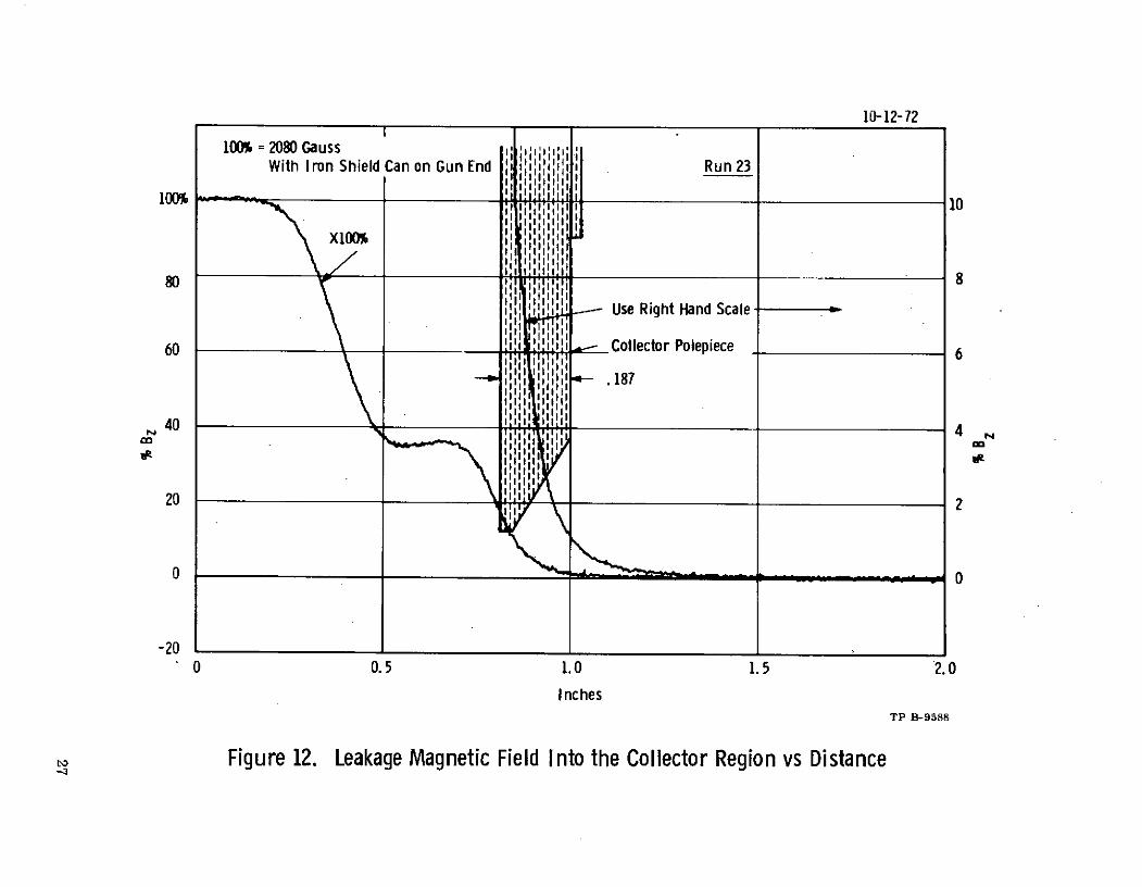
12. Leakage Magnetic Field into the Collector Regionvs Distance ................ 27
13. Magnetic Field in the Cathode Region as a Function ofDistance . . . . . . . . . . . . . . . . . 28
14. Klystron and Focusing Magnet Assembly Layout Drawing. . . 31
15. Klystron and Focusing Magnet Assembly . ...... 33
16. Demountable Electron Gun . ... ........ 35
17. Samarium-Cobalt Magnet . .. . ....... 36
REDWNG PAGE LANK OT F
ix
LIST OF ILLUSTRATIONS (Cont.)
Figure Page No.
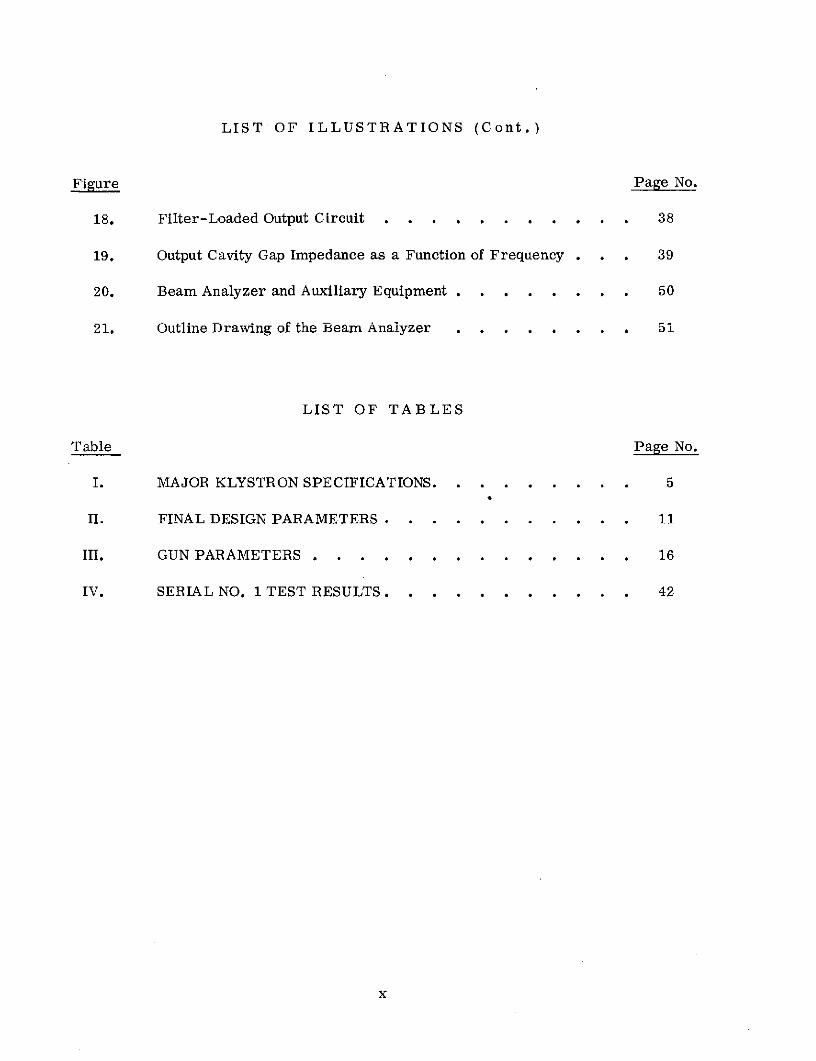
18. Filter-Loaded Output Circuit . . . . . . . . . . . 38
19. Output Cavity Gap Impedance as a Function of Frequency . . . 39
20. Beam Analyzer and Auxiliary Equipment . . . . . . . . 50
21. Outline Drawing of the Beam Analyzer . ...... . 51
LIST OF TABLES
Table Page No.
I. MAJOR KLYSTRON SPECIFICATIONS. . ...... . 5
II. FINAL DESIGN PARAMETERS . . ..... ... . 11
III. GUN PARAMETERS ............. . 16
IV. SERIAL NO. 1 TEST RESULTS. . .... ........ 42
x

1. SUMMARY
A theoretical design for a permanent-magnet focused klystron is described.The objective was to obtain 2. 0 kW cw with 120 MHz bandwidth at 12. 045 GHz and with45% conversion efficiency.
Both large- and small-signal programs were employed to analyze the designand to select design parameters for maximum conversion efficiency.
One klystron was fabricated to verify the analytical design.
The first experimental tube was Brillouin focused with a samarium-cobaltpermanent-magnet focusing structure. A five-cavity design with a filter-loaded out-put cavity was used for the gain bandwidth requirements.
Test results from the one tube fabricated showed the design to have poor beamtransmission due to insufficient magnetic field for rf operation.
The use of an auxiliary solenoid to increase the focusing field improves per-formance, and indicates more field is needed.
The permanent magnet is made up of 52 segments arranged in annular configu-ration, with a radial direction of magnetization.
1

2. INTRODUCTION
This report describes a development and experimental program for a light-
weight, broadband klystron to be used for operation with a NASA-designed multistage
depressed collector. i, 2 One tube and ten demountable guns were to be delivered to
Lewis Research Center.
The first task on the program was the development and analytic optimization of
the design. This was followed by the physical design to achieve the characteristics
selected. The third task was to construct and evaluate the selected design.
One tube was constructed and evaluated.
] pMEDING PAGE BLANK NOT

3. DESIGN APPROACH AND TRADEOFF
CONSIDERATIONS
The basic design approach was to use a conventional five-cavity klystron rf
circuit with drift lengths, drift tube diameters, beam diameters and gap coupling
factors chosen to maximize conversion efficiency. The factors which influenced the
initial choice of parameters are outlined in this section.
3.1 SUMMARY OF TUBE SPECIFICATIONS
The major klystron specifications are summarized in Table I. Those specifi-
cations which most directly affect the choice of design parameters are frequency,
gain, power and efficiency.
TABLE I
MAJOR KLYSTRON SPECIFICATIONS
Electronic Conversion Efficiency 45% min
Center Frequency 12. 045 GHz
Bandwidth 120 MHz
Rf Power Output 1. 0 kW min
Power Gain 40 dB min
Design Life 2 years min
Phase Linearity d2 ¢/dw 2 0.2 /MHz 2
Noise Figure 40 dB max-6
Perveance 0.75 x 10 max
Beam Transmission at Saturation 95% min
Maximum Beam Voltage 16 kV
Demountable Electron Gun
-RECEDTNGc, PAOL BLANK NOT VftB
5
3.2 SUMMARY OF FOCUSING MAGNET SPECIFICATIONS
* Maximum field: 2000 gauss
* Length of focusing field: 7. 62 cm
* Maximum leakage field into collector: +0. 5%
* Field reversal in the collector region: Not allowed
* "Adiabatic Beam Expansion" from the last interaction gapinto the collector
* Demountable collector
* Assembly to be bakeable to 250 C
3.3 INITIAL ELECTRICAL DESIGN
The selected beam power is 4. 444 kW based on a 45% conversion efficiency andan output power of 2 kW. A low beam perveance is desirable to maximize efficiency;however, the length of the rf circuit increases with decreasing perveance, and theweight of the magnet increases as the cube of the length. In addition to these factors,small signal computer analysis shows that at least a 35% increase in the R/Q would berequired, and even this would result in marginal gain-bandwidth.
-6Therefore, the maximum allowable perveance of 0.75 x 10⁻⁶ is the most suit-
able for this tube.
With the parameters chosen so far (i.e., beam power and perveance), thebeam voltage will be 8. 111 kV and the beam current is 0. 548 A.
The normalized tunnel diameter predominantly affects the efficiency and thebeam and gun designs. The minimum practical drift tube diameter is determined bythe beam size, and since the cavity R/Q is also influenced by drift tube diameter, itis doubly important to minimize the diameter of both the beam and drift tube. Con-versely, a lower limit on beam size is set by space-charge effects and by beam opticsand focusing considerations. As the beam size is decreased, the required focusingfield increases, and the magnet weight increases as the square of the focusing field.The required area convergence of the gun decreases with increasing tunnel diameter,while the conversion efficiency decreases rapidly when the normalized tunnel radius,ya, exceeds 0.90 radian.
The required bandwidth of 120 MHz and phase deviation specification dictatethat the second and third buncher cavities be resistively loaded to increase the bunchersection bandwidth. The required bandwidth also makes it necessary to use somethingother than a conventional output cavity. To achieve the necessary output circuit band-width, a filter-loaded output circuit is used.
6

The design approach taken was to make the drift tube diameter and the beamdiameter larger in the buncher section and smaller in the output section. The largertunnel and beam diameter allow the use of a lower convergence gun and a smallermagnet. This has only a minor effect on gain and bandwidth. The smaller tunnel andbeam in the output section are necessary to maintain the conversion efficiency.
The remaining major design parameters are number and Q factors of cavities,interaction gap lengths, and intercavity gap lengths.
7

4. ANALYTICAL DESIGN
The analytical design procedure was based on several Varian computer pro-grams which model electron trajectories and the rf interaction process in a klystron.
These programs were used to refine the initial design; i. e., to ensure that the klystron
would perform with proper gain and bandwidth, as well as to predict the efficiency.Because the programs are basically analytic rather than synthetic in nature, it wasnecessary, in order to synthesize a design, to compute a number of designs in order
to systematically optimize a given parameter.
4.1 REVIEW OF ANALYTIC CAPABILITY
The main analytical tools used in this program were our small-signal andlarge-signal computer programs for klystron amplifiers, with computer programsand beam analyzers used for the electron gun and beam design.
The small-signal computer program is based on space-charge wave theory andis capable of predicting the small-signal gain and phase delay, and the first and second
derivatives of the phase delay, as a function of operating frequency. The small-signalanalyses were used in the selection of the number of cavities and for adjustment of thetuning and loaded Q factors of the resonators. The final adjustment of the tuningpattern, however, was done experimentally.
The large-signal computer program used in the tube analysis is based on aprogram developed at Cornell University, modified to account for the effect of the drifttube on the rf space charge forces. 3 This program has been capable of predicting theefficiency of klystron amplifiers within about 5 percentage points at the 50% efficiencylevel, and within about 10 percentage points at the 70% efficiency level. The large-signal program is used for comparison of the efficiency of different designs and forcalculation of the optimum loading of the output resonator. No specific large-signalcalculations were made for this tube design, but use was made of the general designconcepts for selection of parameters derived in previous company-sponsored studyprograms.
The gun design computer program solves the electron trajectories for arbitrarybeam flow problems including space charge, axially-symmetric magnetic fields, rela-tivistic effects (including the self-magnetic field of the beam) and the effects of thermalvelocities. In addition to the design of electron guns, collector beam spread calcula-tions may also be performed with this program.
Varian's beam tester thoroughly evaluates the performance of actual gun con-figurations. Salient features of this machine include a pinhole and split-collectorarrangement which can be used to scan the beam in two transverse directions as well
PRECEDING pAGE BLAN NOT PXM9

as along the beam axis, a well-shielded solenoid so that measurements can be madewith an applied focusing field, and an oil-free vacuum chamber.
4.2 SMALL-SIGNAL ANALYSIS
The initial small-signal analysis began by using assumed design parametersselected as feasible values from previous work on similar tubes. This was primarilya verification process to show that the basic tube specifications could be met with afive-cavity approach, and will not be discussed in detail. The next step was the actualdesign and cold test of the individual cavities, providing measured cavity character-istics for use in the small-signal computer calculations.
The chosen and measured parameters for the first tube are listed in Table II.These figures were used to compute the small-signal gain, bandwidth and phase re-sponse. The results of the final computations are shown in Figure 1, which is theactual computer terminal printout.
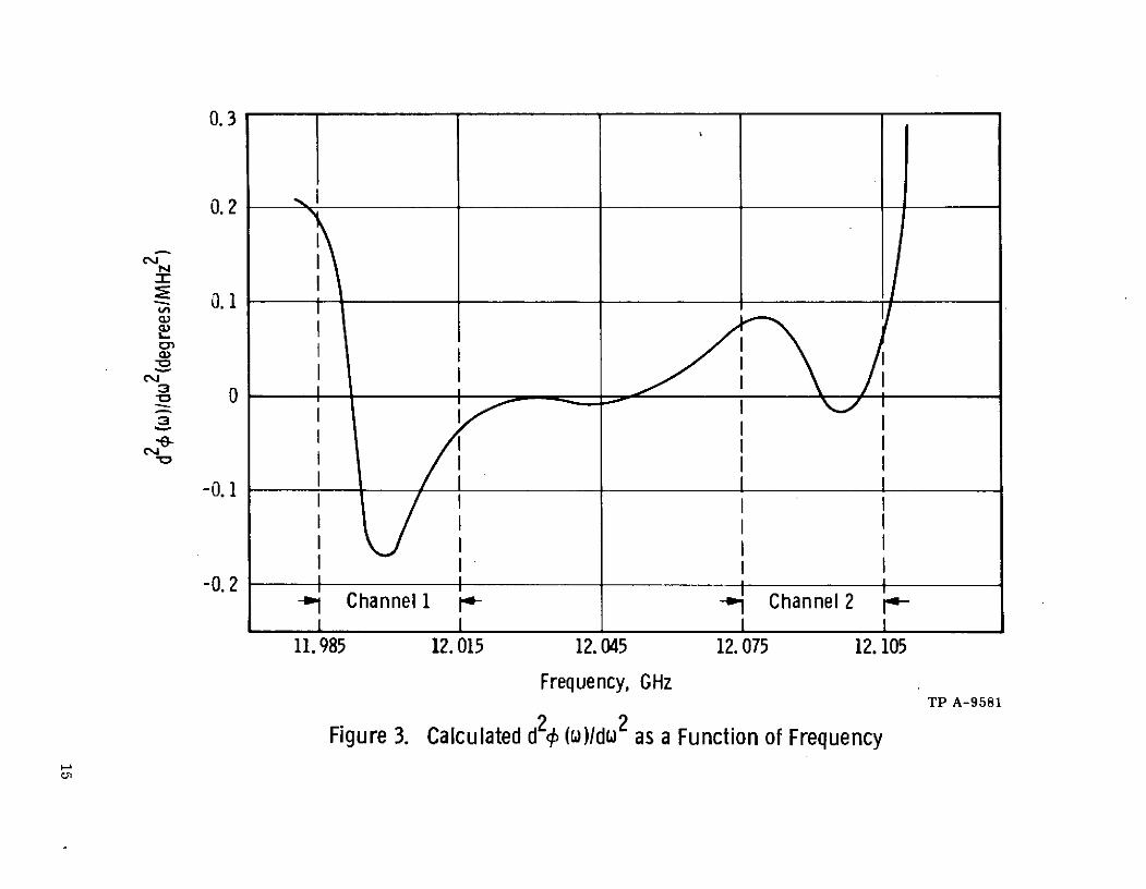
The small-signal gain is 47. 7 dB, as shown in Figure 2. The bandwidth ofChannel 1 is just shy of the required 40 MHz and the bandwidth of Channel 4 is slightlyover 40 MHz. A slight tuning adjustment would give the necessary bandwidth onChannel A. The cavity tuning scheme is given under F (GHz) (Figure 1). Channels Aand B are to be used as guard band and the gain does not drop below 3 dB. Figure 3is the calculated d 2 0 (w)/dw 2 as a function of frequency. The specification of a maxi-mum second-order phase deviation of 0.2 0/MHz2 is not met in Channel 1, but is with-in specification in Channel 2. To reduce the second order phase deviation in Channel 1will require more loading in the cavities; however, this in turn will reduce the gain.
4.3 ELECTRON GUN AND BEAM DESIGN
The electron gun is of the type commonly referred to as Brillouin focused.The object of the design is to obtain a beam which is laminar and with minimumscalloping, and maintained in equilibrium with a magnetic focusing field of theBrillouin value. Since experience has shown that some difficulty may arise in main-taining adequate focusing under rf conditions, the design approach is to have the beamenter the magnetic field at the Brillouin value, then gradually increase the focusingfield to 1. 5 times the Brillouin field at the last interaction gap.
The gun used on the tube is a modification of an existing gun. The modifica-tions are made and the results checked in the beam analyzer. After several trialruns in the beam analyzer, a suitable gun was finalized. Table III shows the majorgun parameters.
10

TABLE II
FINAL DESIGN PARAMETERS
Frequency 12. 045 GHz
Bandwidth 120 MHz
Beam Voltage 8. 111 kV
Beam Current 0. 548 A-6
Beam Perveance 0. 75 x 10-6
Beam Area Convergence 46:1
Cathode Loading 1. 73 A/cm 2
Cathode Diameter 0. 635 cm
Number of Cavities 5
R/Q Input Cavit 124
R/Q Second Cavity 124
R/Q Third Cavity 124
R/Q Fourth Cavity 105
R/Q Output Cavity 110
Normalized Length of Interaction
Gaps
1st Gap 1. 02 radian
2nd Gap 1.02 radian
3rd Gap 1. 02 radian
4th Gap 1.02 radian
Output Gap 0. 69 radian
Normalized Tunnel Radius, ya
Cavity Numbers 1, 2, 3 1. 067 radian
Cavity Numbers 4 and 5 0.90 radian
Tunnel Diameter, Cavity 1, 2, 3 0. 151 cm
Cavity 4 and 5 0. 127 cm
11

TABLE II (Cont.)
Beam-Filling Factor, b/a
Cavity 1 0.62
Cavity 2 0. 49
Cavity 3 0.43
Cavity 4 0.52
Cavity 5 0.55
Drift Lengths
S1, 2 1. 27 cm
f 2,3 1. 27 cm
f 3, 4 1. 00 cm
j 4.5 0. 635 cm
Normalized Drift Length
p f 1,2 1.27 radian
q f 2,3 1. 54 radian
fp 3,4 1. 12 radian
p f 4,5 0.712 radian
Magnetic Focusing Field at theLast Interaction Gap 2000 gauss
12
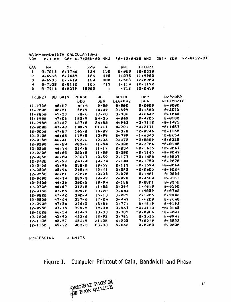
(GAIN-eANDWIDTH CALCULAllUNSVO= 81 KV GO= 6.7500E-05 MHO F0=12*0450 bHZ OEl 200 W/Q0=12*97
CAV M+ M- H/Q Q BOL F ( HZ)1 0.7216 0.7746 124 150 0*000 12*03302 0.6985 0.7669 124 450 1*278 11*99003 0*6935 0.7610 124 300 1.538 12*09004 0.7538 0*8112 105 713 1*114 12*11925 0.7916 0*8379 18000 1 *712 12*0450
F(GHZ) DB GAIN PHASE DP DP/DF D2P D2P/UF2DEG DEG DEG/MHZ DEG DEG/MHZt2
11.9750 40.07 44*4 0000 00000 0*0000 00000011.9800 42*81 5809 14.49 2.899 501883 0*207b1109850 45.33 78*6 19*68 3e936 4*6649 0*186611.9900 47*06 102*9 24.35 4e869 0*4705 0*018811.9950 47*67 127*8 24.82 4.963 -3*7118 -00148512.0000 47*49 148*9 21.11 4*221 -42171 -08168712*0050 47.07 165*8 16*89 3.378 -2*8946 -0.115812-0100 46*68 179.8 13*99 2*799 -16343 -0.065412.0150 46*41 192*1 12.36 2*472 -0*8209 8-0832812.0200 46*24 203*6 115 4 2*308 -0*376 -0*014812.0250 46#.14 2148 11*17 2.234 -091665 -0*006712.0300 46.08 225*8 11000 2.200 -0*1165 -80004712.0350 46.04 236*7 10.89 2.177 -0*1425 -0.005712-0400 45*99 247.4 18074 2.148 -0*1750 -00007012.0450 45*96 258-0 10*57 2*113 -0*1594 -0.006412.0500 45*96 268*4 10.41 2*082 -0*0605 -0.002412.0550 46*01 278*8 10*35 2*070 001401 0.005612*0600 46*14 289.3 10*49 2*098 0*4524 0*018112-0650 46*36 300.2 10.94 2.188 008801 0.035212.0700 46.67 312,0 11082 2*364 104010 0*056012.0750 47*05 325*2 13*22 2.644 1*9059 0.07621200800 47.42 340*4 15.*13 3-025 2*1085 0.084312.0850 47.64 357*6 17*24 3.447 1-6200 0.064812.0900 47.56 376*5 18.86 3*771 0.4819 0.01931200950 47.15 395.8 19*34 3.867 -8 4113 -0.016512.1000 46*54 414.7 18*93 3.785 -0.0026 -0.000112.1050 45.95 433.6 18.92 3.785 2*3535 0.094112-1100 45.57 454*9 2128 4.255 7.0549 0-282212.1150 45.12 483.3 28*33 5.666 0*0000 0.0000
PROCESSING 4 UNITS
Figure 1. Computer Printout of Gain, Bandwidth and Phase
AILX213

50
Channel 1 Channel A annel1 Channe A Channel B Channel 2 -
48 I I
2 dB I
46
44
42
4011. 985 12. 015 12. 045 12. 075 12. 105
Frequency, GHzTP A-9580
Figure 2. Computed Small Signal Gain as a Function of Frequency
0. 3
0. 2
0.1.I
-0. I
oI I
-0. 1
-0. 2 I I I I- Channel 1 ,- -i Channel 2 r*I I I I
11.985 12.015 12.045 12. 075 12. 105
Frequency, GHzTP A-9581
Figure 3. Calculated d2c (M)/dI2 as a Function of Frequency
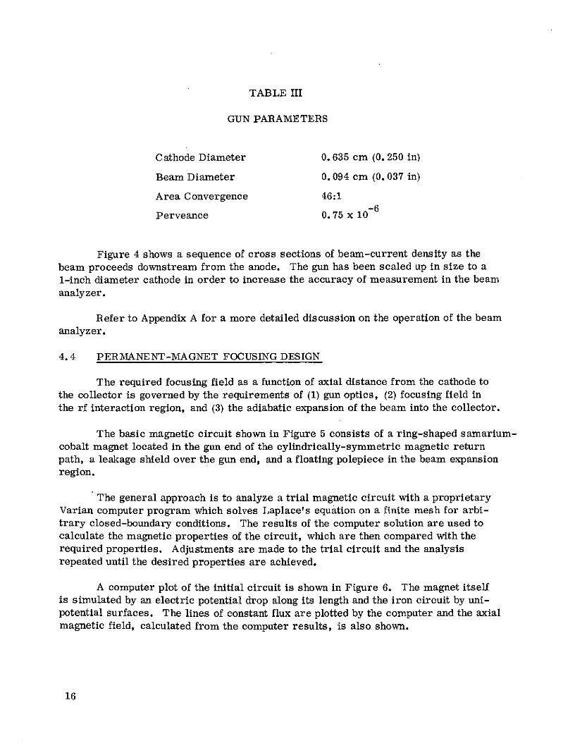
TABLE III
GUN PARAMETERS
Cathode Diameter 0. 635 cm (0. 250 in)
Beam Diameter 0. 094 cm (0. 037 in)
Area Convergence 46:1
Perveance 0. 75 x 10-6
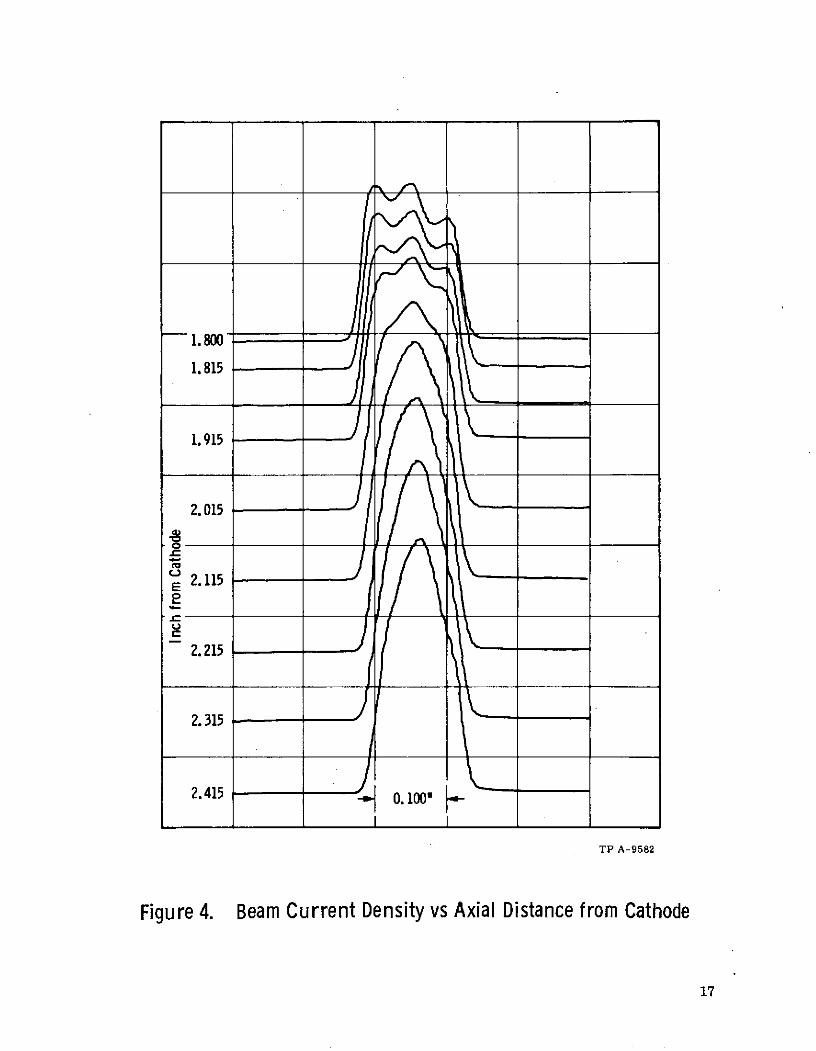
Figure 4 shows a sequence of cross sections of beam-current density as the
beam proceeds downstream from the anode. The gun has been scaled up in size to a
1-inch diameter cathode in order to increase the accuracy of measurement in the beam
analyzer.
Refer to Appendix A for a more detailed discussion on the operation of the beamanalyzer.
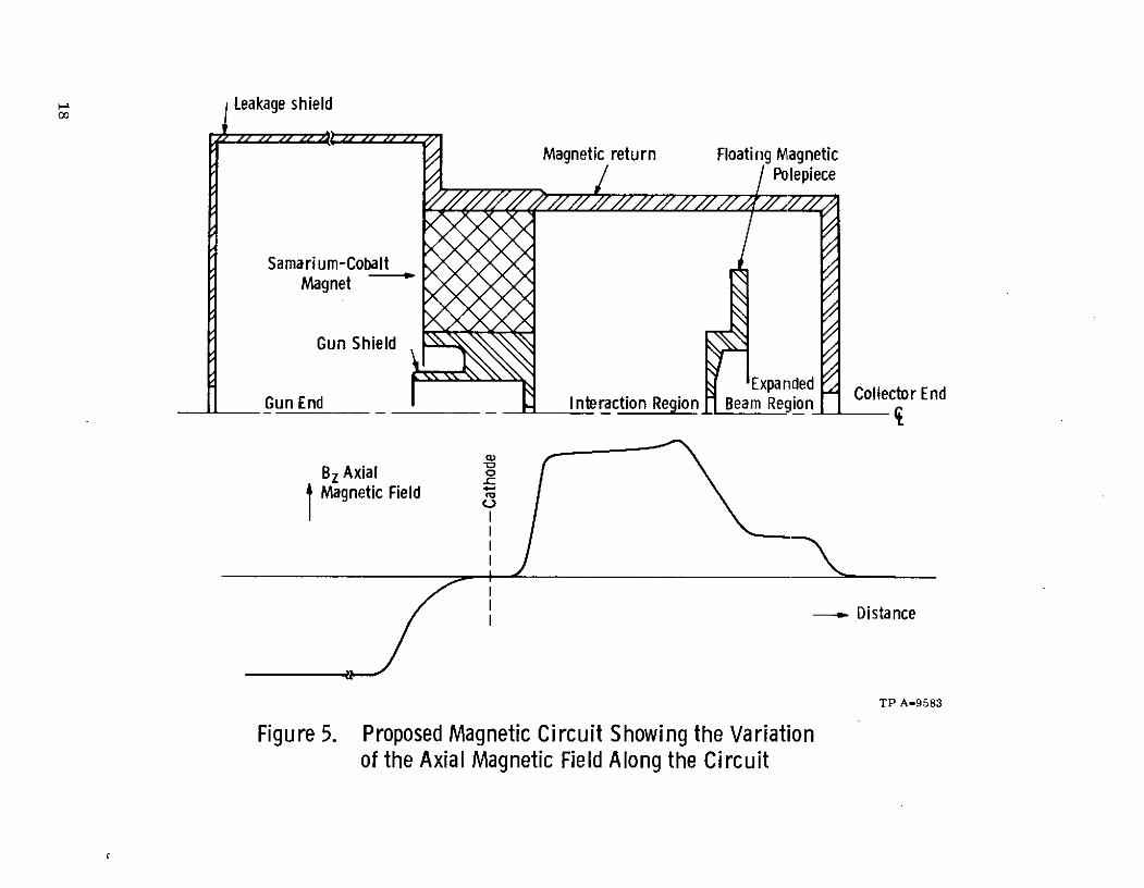
4.4 PERMANENT-MAGNET FOCUSING DESIGN
The required focusing field as a function of axial distance from the cathode to
the collector is governed by the requirements of (1) gun optics, (2) focusing field in
the rf interaction region, and (3) the adiabatic expansion of the beam into the collector.
The basic magnetic circuit shown in Figure 5 consists of a ring-shaped samarium-cobalt magnet located in the gun end of the cylindrically-symmetric magnetic returnpath, a leakage shield over the gun end, and a floating polepiece in the beam expansionregion.
The general approach is to analyze a trial magnetic circuit with a proprietaryVarian computer program which solves Laplace's equation on a finite mesh for arbi-trary closed-boundary conditions. The results of the computer solution are used tocalculate the magnetic properties of the circuit, which are then compared with therequired properties. Adjustments are made to the trial circuit and the analysisrepeated until the desired properties are achieved.
A computer plot of the initial circuit is shown in Figure 6. The magnet itselfis simulated by an electric potential drop along its length and the iron circuit by uni-potential surfaces. The lines of constant flux are plotted by the computer and the axialmagnetic field, calculated from the computer results, is also shown.
16
1. 800
1. 815
1.915
2.015
E 2.115
-
2.215
2. 315
2.415 0.100"
TP A-9582
Figure 4. Beam Current Density vs Axial Distance from Cathode
17
Leakage shield
Magnetic return Floating MagneticPolepiece
Samarium-CobaltMagnet
Gun Shield
Expandedm d Collector EndGun End Interaction Region Beam Region
Bz Axial oI Magnetic Field
- Distance
TP A-9583
Figure 5. Proposed Magnetic Circuit Showing the Variationof the Axial Magnetic Field Along the Circuit

Lm =].6 inchdr =0.05 Hm =1.6inchdz = 0.10 B/H =1.4
4 , , ,----- ----- - -.. V .3 . .. .I -.
4-- ... --. SmCo Magnet :7.
I00 N I
0 -- . .. --
' I F-
i 1I L.
0 1 2 3 4 5 6 7 8Inch
Figure 6. Computer Printout of Initial Magnet Design

The samarium-cobalt magnet has an ID of 7. 11 cm (2.8 in), an OD of 15. 24 cm(6. 0 in), a thickness of 4. 06 cm (1. 6 in), and weighs 4. 68 kg (10. 3 lb). The maximumfield is 2070 gauss. The shape and position of the floating polepiece gives approxi-mately the required field shape for the beam expansion region. The final size andshape of the floating polepiece was determined experimentally on a half-scale model byvarying the configuration, measuring the magnetic field, and then computing the beamtrajectories on the computer program.
Figure 7 is an expanded detail of Figure 6 to show the location of the inter-action gaps.
The operating point of the magnet is on a load line of 1. 4 which is at the pointof maximum energy product. Figure 8 is a plot of energy product vs load line, andshows little variation of the energy product as the load line varies between 1 and 2.
Figure 9 shows the demagnetization curves for the Varian-manufacturedsamarium-cobalt magnets for various stabilization temperatures. The design isbased on a magnet stabilized at 300 0 C.
4. 4. 1 Experimental Results
A one-half scale model of the circuit shown in Figure 6 was con-structed to check the computed design. Figure 10 shows the experimental vs com-puted data normalized to 100% Bz. Close agreement is shown in the rf interactionregion and less field is shown in the beam expansion region. The reason for this isthat the experimental circuit was made with a larger hole in the floating polepieceand exit magnetic shield because more space was needed in this area to fit the tube.The magnetic circuit is sketched in to show its relationship to the field.
The next task was to alter the collector and floating polepieces andcompute the beam trajectory, then repeat the procedure until adiabatic beam expan-sion is achieved. The result is shown in Figure 11. The beam traverses the outputgap with a diameter of 0. 027 inch and gradually expands to 0. 110 inch in a distance of0.9 inch, remains constant for 0. 3 inch, and then gradually expands into the collectorregion.
Using a value of 8. 15 kV for the beam voltage and 2070 gauss for themagnetic field, the cyclotron wavelength is:
VkV 8.15Xc = 264 - 264 - 0.314 inch;B gauss 2070
therefore,
2Xc = 0.728 inch
20

NAS-Leis ag.Fl.Bfli~lti~i~~ 8f~tf~ti~tf~Ai VKM y, -~i~f~~flFf~ iifi~frff Computed field from plot of 5-22-725-22-72 MN :4
5 'T, L, PiP'll W. No ~~~it: f - -1 AA na HAriMAI-l a EE i Sm-co Magnet .;;A E . .VE .
i:: toT A AS
:::::: Axial magnetic L11:l. I I1..*tif .(L. ti. iW -. lt:-I+ t.t~
:::B~a20 gauss14105 AMN 14 Ii30MOO
A : I . :-hy"B "'M::: i I " 1kyjz M it 4,ME s TH ini P n s s toit H MEA; A j]'4 PHHAM4R - TRNWOons,404LIN PC ai y- n-HR -& i H NA ot= 21E -Hi i~i i; 00
~ttir-, .- RE ot i BE Tz HE WYHE up to to NN I,,_- of is No Eyo 1500toH4hi i N- H ! :I D v. A I 1.41
isU o n i OPitII it i~l'F-li EPta at I. . al 1000
MH HH ll H i A:
Z7 T:=Q "I', owl U uism W mou Ughww" W R th INNER ; to voldiito Ajlrt~ili~ijiili:i~
::: ! :I frtNur
Ri*E ! HIM"
a TT :: W M , 1 ZM 1-PHW U W A ,o n sH I oa 4 4 i WAl a on I NYE1MEupi H H I I 1WI
oi1Wu 4. T d P -aM
j tpq P a iiC T RV i *40140411 o STgg a z t ON do a 'T:5Yk no 1 FAp

-8100Bm = 5-00 Hm + 8100
12 (Samarium-Cobalt)Stabilized at 3000 C
10
4
0. 1 1. 0 10. 0 100. 0
Load Line BmIHmTP A-9584
Figure 8. Energy Product vs Load Line
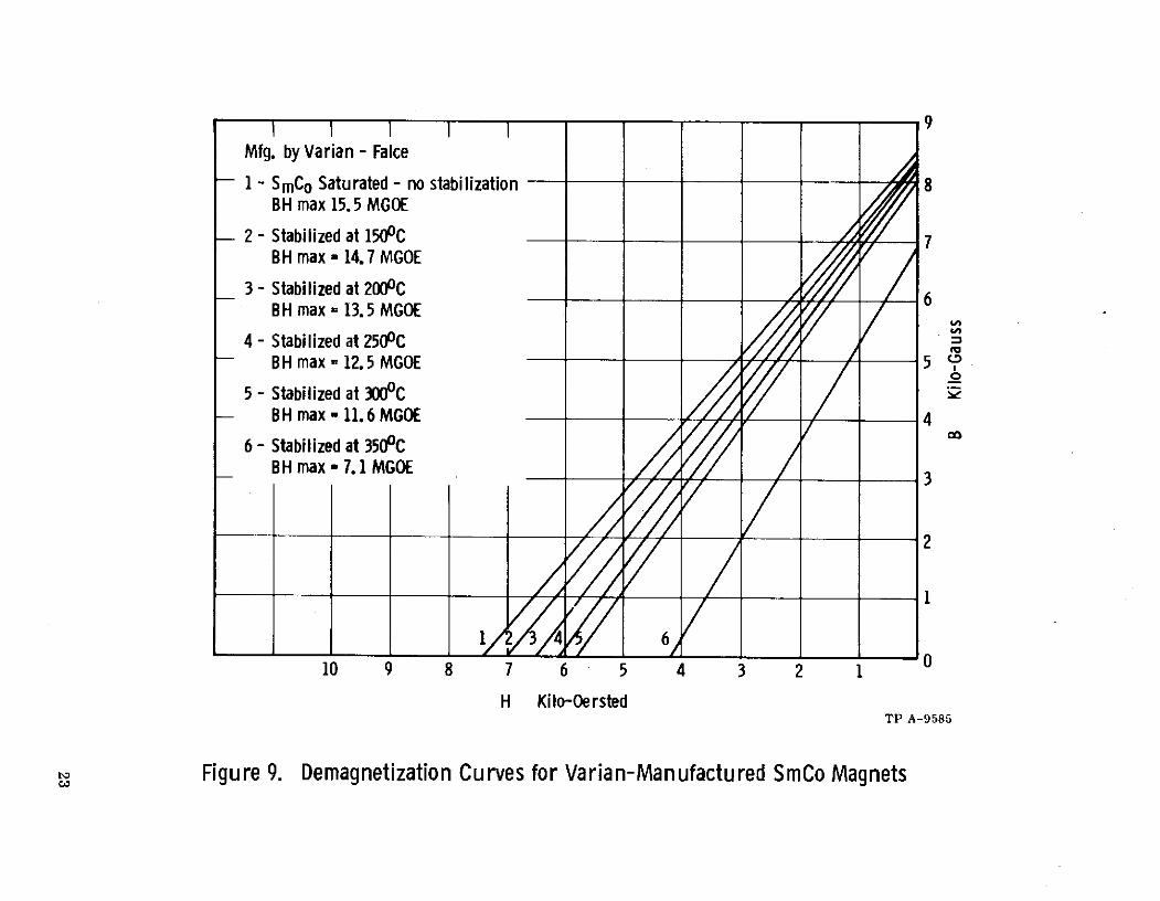
Mfg. by Varian - Falce
1 - SmCo Saturated - no stabilization 8BH max 15.5 MGOE
-2 - Stabilized at 1500C 7BH max - 14.7 MGOE
3 - Stabilized at 2000C 6BH max = 13.5 MGOE
4 - Stabilized at 2500CBH max - 12.5 MGOE 5
5 - Stabilized at 3000CBH max - 11.6 MGOE 4
6- Stabilized at 3500CBH max - 7.1 MGOE 3
14 6
10 9 8 7 6 5 4 3 2 1
H Kilo-OerstedTP A-9585
Figure 9. Demagnetization Curves for Varian-Manufactured SmCo Magnets

__ _ __ _ _ Ii I I Il
T 1001 2070 Gauss _ ;
SmCo Magnet Experimental i 111
CollectorPolepiece/ Computede
FloatiI IngIIIat I1 I 11
Polepiece
60 - -l-l- -l
iLCathode Polepiece.
40
"W11 I'111111a
1 1 I I
0 0.5 1.0 1.5 2.0 2.5
InchesTP A-9586
Figure 10. Experimental vs Computed Data Normalized to 100% Bz

VKX-7794 Magnet Run No. 21I ,i i,., , I ,- / _ _ _I I I I
Without Iron Can over Gun End 1/2 scale magnetcircuit I I
I II IIII I l111 lll111SIIII III
IIIIII BeamI:Collector Diameter
100 i Polepiece 1Diameter 0.20
80 0.14
40 0.08
III
250 dia.
0 0
0 1.0 2.0 3.0 4.0
Inches Full ScaleTP B-9587
Figure 11. Magnetic Field and Beam Trajectory as a Function of Axial Distance
, :, : I I , •IO I I ..._ II
1.0 2.0 3.0 4.0Inche Ful ScaleI
I~T B-9587 I
Figure~~~~~~~~~~~~~ 11 Manei Fil an Be Trjctr aaFucioofAilDsac

The length of the tapered field is 0. 75 inch and meets the require-ment that the tapered field must be greater than 2X c.
The tunnel diameter tapers out to 0. 200 inch before entering thecollector.
The electron beam is required to exit into a magnetically field-freecollector. The maximum collector field at a position two exit hole diameters beyondthe collector polepiece face must be less than 0. 5% of the focusing field.
The collector polepiece configuration and the resulting measuredmagnetic field is shown in Figure 12.
This polepiece configuration produces a maximum collector fieldless than 0. 5% of the focusing field. A large cylindrical shield around the gun end ofthe magnet must be used to prevent stray leakage fields from producing a negativefield in the collector region. If this shield is not used, the collector field may be ashigh as -2%.
The next task was to examine in detail the magnetic field at thecathode. For Brillouin flow, there must be no field at the cathode. The initial designhad a -1% field at the cathode; this was deemed to be excessive for good beam optics.Again by trial, the polepiece configuration around the cathode was modified for mini-mum field at the cathode. The final result is shown in Figure 13 and shows the fieldat the cathode to be -0. 1%. This was judged to be close enough to zero to give propergun performance.
4.5 COLLECTOR DESIGN
The collector is from an existing 10 kW klystron anc easily handles the powerlevel involved. The maximum power density is 3. 15 kW/in
26
10-12-72
100 = 2080 Gauss 3 ,
I IIIWith Iron Shield Can on Gun End Run 23
100 " ... X10 IIIIII II0111111 I
Use Right Hand Scale
60 _l Collector Polepiece 6
40 4
20 2
0 0
-200 0.,5 1.0 1.5 2.0
InchesTP B-9588
Figure 12. Leakage Magnetic Field Into the Collector Region vs Distancet\3 Figure 12. Leakage Magnetic Field Into the Collector Region vs Distance

ND_ Run '"W 9-7-7200100
100% = 2300 Gauss
80 X X 1/10
60
Xl
40
20
'
-200 0.5 1.0 1.5 2.0
I nches TP A-9589
Figure 13. Magnetic Field in the Cathode Region as a Function of Distance

5. MECHANICAL DESIGN
The mechanical design of the VKX-7794 resembles that of many other Varianklystrons at this general frequency range. The major departures from conventionaldesign are brought about by the requirement that this tube must be operable inside a
space-simulating vacuum chamber. A removable collector must be provided whichcan be replaced by a multistage depressed collector for efficiency enhancement studies.
The electron gun is also required to be demountable so that it may be replacedat end of life.
The focusing magnet assembly is also unusual in that it must withstand bakeoutat high temperature so that the system may be evacuated to the pressure levels appro-priate to klystron operation.
Figure 14 shows the layout drawing with the tube mounted in the permanentmagnet focusing assembly. Figure 15 shows a photograph of the tube and magnetassembly.
5.1 RF BODY CONSTRUCTION
The buncher cavities are milled from a solid copper block with thin Monel-backed copper diaphragms brazed into the open ends. The diaphragms are connectedto a tuner mechanism for final trim tuning during hot test.
Water cooling of the body block is accomplished through a series of transversecooling passages drilled through the web between cavities. A heavy copper block isbrazed to the body between the input and output waveguides. If possible, a heat pipeis to be attached to this block to conduct away the heat dissipated in the body. In thelatter case, direct water cooling of the body will not be necessary.
The input coupling is by way of WR -90 waveguide through a pillbox-type cer-amic window, through a tapered transition to half-height waveguide, and through appro-priate waveguide bends terminating at the input coupling iris. The output coupling isby way of WR -90 waveguide through a pillbox-type ceramic window, through a full-height waveguide to the filter loaded output cavity.
The gun and collector polepieces are made of soft iron and brazed to the bodyassembly, and are sized to mate snugly with the magnet polepieces, thereby completingthe magnetic circuit.
29

8 I7 I I a 2 1
OF POOR QUALITS
G G
0-//
-A?- 6Z
0444o t UE. O. U ,
T 14-- -- 12E 0 ,
oFigure 14. Klystron and Focusing Magnet Assembly Layout Drawing
_4PRECEDING PAGE BLANK NOT :10rev , a 4 4
... *c. 7 05527 I

- I~~~~ .~ ~ _ ,~ ; l__, =:-'i.-
~~;: . rl:: ,C - i~ 3 ii- i~,_;:~":~ i~:: :I ~-.. .tE- -- Pi il-
ef~ ~~O-,.. ,~ ;~ ~, ;: ~ ~ i~~ . i !iii8_.~i~-_-i- !r:F:li
I ~I:~ ~~ ,_ :. - !a~-i~ii--i !i:- .~:~ ,zs _ _~.r li -- : :. ZIilt- ; C-~ r-r~ . ~~8 -a:~:.8i: ~-E:I ! .,l-sii-li :
2~igure 15. lysron nd ocusng anet Assembly:
OOR QI]AL PRECEDING PAGE BLANK NOT

5.2 RF WINDOWS
The input and output waveguide windows consist of thin disc ceramics mountedin circular waveguide, which is an existing design used on a 4 kW cw klystron. TheVSWR is less than 1. 1:1 across the operating band.
5.3 COLLECTOR
The collector is of conventional design, taken from a 10 kW klystron. It issupported by a ceramic insulator in order to allow for the measurement of beam trans-
mission. The major feature of the collector design is the heliarc flange by which it ismounted to the collector polepiece. This is designed to allow maximum unimpededaccess to the beam exit tunnel upon removal of the collector.
5.4 ELECTRON GUN CONSTRUCTION
Figure 16 shows the demountable electron gun. The gun ceramic supportcylinder is made large in order to minimize leakage. The cathode employed is adispenser-type cathode, because an oxide-coated cathode could not be expected to pro-vide the cathode current density required in this application. The cathode is supportedby a conical sleeve which is attached to the inside of the focus electrode support sleeve.This assembly is brazed to a heavy support ring attached to the base of the gun ceramicby means of six machine screws.
The original gun vacuum envelope is completed by a secondary feedthroughstructure that is heliarc welded to a sleeve at the base of the gun ceramic and to theheater feedthrough rod. At the time of gun replacement, these heliarc joints are cutand the secondary feedthrough plate discarded. The new gun is then mounted in placeof the old gun, using the machine screws.
5.5 PERMANENT MAGNET CONSTRUCTION
The permanent magnet assembly consists of a total of 52 segments of samarium-cobalt magnets as shown in Figure 17. Each of the two rings shown consists of 26 seg-ments which are magnetized before assembly. The rings are placed on top of eachother, then clamped into the iron cylinder with stainless steel plates.
The floating polepiece is attached to the tube body downstream from the outputcavity.
5.6 FILTER-LOADED OUTPUT CIRCUIT
The filter-loaded output circuit consists of a conventional klystron outputcavity which, in turn, is iris-coupled to the output waveguide.
34

Figure 16. Demountable Electron Gun

0 12 3 4 6 INHES
0 2.5 5.0 7.5 10.0 12.5 15.0 CM
Figure 17. Samarium-Cobalt Magnet

Figure 18 shows the filter-loaded output circuit. Figure 19 shows the realpart of the gap impedance as a function of frequency. The graph shows that the maxi-mum circuit impedance is 16, 000 ohms instead of the desired 18, 400 ohms. This willresult in slight over-coupling to the beam and may reduce the efficiency a slight amount.The bandwidth is 40 MHz for the lower channel and 49 MHz for the upper channel. Therequired bandwidth is 40 MHz for each channel.
37

S3 4 11B 2 1REVISIONS
.019 A ZONE ILTR DESCRIPTION DATE APPROVED
0 200
O.
.90B T -E
S cIRIS -
f&VIT_( T_ I _ CvIT_ TPUT "..,E- Aui..'EQ.Z.cO13, 1I2.k .400 x .900 N(.
S 1 i o QTY I IDENTIFYING NUMBER IDESCRIPTION ICODE IDENT ITEM
LIST OF MATERIALS
-- DIMSISI Ao I I N IACHS iall varlan
AAT RI Dt APPD
S- ofSI, Act I VIt, APP.o1 SIZE CODE IDENT NO-
.NEXT ASSEMBLY E D ON .C....._ IAA El AAZ TO IW I l USD ON S!1 AA
VITIS Q SCL APPLICATION SL SHEET
3440.09-02 8/68 + SUPERSEDES
Figure 18. Filter-Loaded Output Circuit

20
16
- 12
S-2 dB- --
t-a 40 MHz I - 49 MHz I
i 4
011.950 12. 00 12. 105 12. l:0 12. 140
Frequency, GHzTP A-9590
Figure 19. Output Cavity Gap Impedance as a Function of Frequency

6. EXPERIMENTAL RESULTS
6.1 COLD TEST RESULTS
The preliminary cold test work required for selection of cavity dimensionswas done on individually-machined copper test sections. Several existing Varianklystrons at similar operating frequencies use the milled-cavity approach, wherecavities with full-radius sidewalls are milled into a solid copper block. A beam hole
is drilled and the drift tubes are brazed in. This technique has the advantage of beingsimple and precise, and results in a good thermal design.
The tunnel diameter and drift tube gaps were determined in the analytical designphase of the program, and the cold-test design work was aimed at achieving a cavity
size that had the proper resonant frequency, good form factor and maximum R/Q.
Using quartz rod perturbation techniques, the measured R/Q of the first threecavities is 124 ohms and the Q is 2800.
The coupling iris for the input cavity is also machined into the copper bodyblock, with the dimension of the coupling iris determined by the desired external Q of225. Since the presence of the coupling iris also detunes the cavity resonant frequency,an adjustment in cavity length is made to re-establish the desired frequency.
The short drift length desired between the penultimate cavity and the outputcavity places a limitation on the length of the downstream drift tube tip. Since the
cavity and drift tube size used on the first three cavities would cause the drift lengthto be too great for good efficiency performance, the gap in the penultimate cavity wasmoved off center toward the output cavity. This, in turn, lowered the resonant fre-quency of the cavity to a point where the cavity height had to be reduced (to 0. 635 cm)to obtain the desired operating frequency, which in turn lowered the cavity R/Q to 105.
To maximize efficiency, the output cavity has a shorter output gap (0. 7 radian)than the driver cavities. This shorter gap and the presence of the output coupling irislowers the resonant frequency; therefore, the cavity height is reduced to 0. 508 cm tocompensate for this. The gap is centered in the cavity and the R/Q is 105.
A copper diaphragm end-wall trim tuner is used on all cavities to provideapproximately ± 100 MHz tuning with a diaphragm movement of ± 0. 05 cm.
The second and third cavities have a small iris coupled to a circular waveguidethat contains a lossy silicone-carbide loaded ceramic pellet to provide for externalloading. This is necessary to increase the driver section bandwidth to cover the re-quired 120 MHz. The amount of loading is determined from the small signal gain band-width program. The position of the pellets is adjustable so the loading may be changedduring rf testing.
PRECEDING PAGE BLANK NOT M1 41
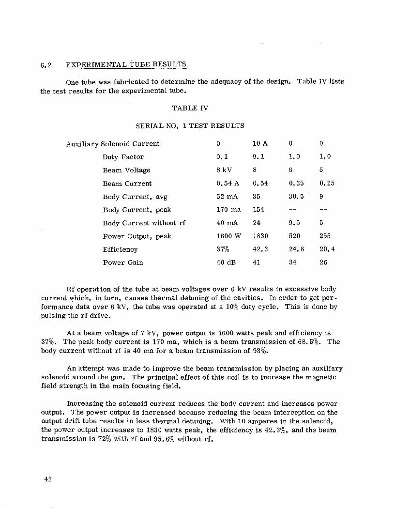
6.2 EXPERIMENTAL TUBE RESULTS
One tube was fabricated to determine the adequacy of the design. Table IV lists
the test results for the experimental tube.
TABLE IV
SERIAL NO. 1 TEST RESULTS
Auxiliary Solenoid Current 0 10 A 0 0
Duty F'actor 0. 1 0. 1 1. 0 1. 0
Beam Voltage 8 kV 8 6 5
Beam Current 0.54 A 0.54 0.35 0.25
Body Current, avg 52 mA 35 30. 5 9
Body Current, peak 170 ma 154 -- --
Body Current without rf 40 mA 24 9.5 5
Power Output, peak 1600 W 1830 520 255
Efficiency 37% 42.3 24.8 20.4
Power Gain 40 dB 41 34 26
Rf operation of the tube at beam voltages over 6 kV results in excessive body
current which, in turn, causes thermal detuning of the cavities. In order to get per-
formance data over 6 kV, the tube was operated at a 10% duty cycle. This is done bypulsing the rf drive.
At a beam voltage of 7 kV, power output is 1600 watts peak and efficiency is37%. The peak body current is 170 ma, which is a beam transmission of 68.5%. Thebody current without rf is 40 ma for a beam transmission of 93%.
An attempt was made to improve the beam transmission by placing an auxiliarysolenoid around the gun. The principal effect of this coil is to increase the magneticfield strength in the main focusing field.
Increasing the solenoid current reduces the body current and increases poweroutput. The power output is increased because reducing the beam interception on theoutput drift tube results in less thermal detuning. With 10 amperes in the solenoid,the power output increases to 1830 watts peak, the efficiency is 42.3%, and the beamtransmission is 72% with rf and 95. 6% without rf.
42

The test results show that a Brillouin-focused beam cannot maintain good beamtransmission under rf conditions. With 10 amperes in the auxiliary solenoid the fieldat the last interaction gap is 1. 8 times the Brillouin field and indications are that morefield is desirable - which is approaching confined-flow operation.
The best cw operation without the auxiliary coil is at a beam voltage of 5 kV;that is, with reasonable beam transmission and without thermal drift. This corre-sponds to a field of 2. 03 times Brillouin at the last interaction gap. This indicatesthat in order to operate satisfactorily at 8 kV the focusing field must be increased byat least 40%. The weight of the samarium-cobalt magnet would increase by a factorof two.
43

7. CONCLUSIONS
An experimental program has been undertaken to demonstrate the feasibilityof techniques for achieving 45% conversion efficiency in a samarium-cobalt permanentmagnet, Brillouin focused, 2 kW cw klystron operating at 12. 045 GHz.
One tube was built to determine the feasibility of the design approach taken.
After determining the value of the focusing field and choosing its shape, acomputer program was used to determine the necessary size and shape of the focusingstructure. Magnetic field measurements made on the computer-designed circuit showgood agreement with the computed design. The limitation of this program is that thepermanent magnet must be cylindrically symmetric.
The poor beam transmission under rf conditions has made it extremely difficultto extract meaningful data. Thermal detuning of the penultimate and output cavitiescauses changes in bandpass characteristics, power output and gain.
Also since a large portion of the beam current does not traverse the outputgap, the cavity parameters are not the same as the design parameters, resulting inpoor rf performance.
The best performance is achieved by using an auxiliary solenoid to increase thefocusing field to near confined-flow condition.
The program has shown that in order to achieve high efficiency and high cwpower at 12. O0 GHz, it is necessary to use confined-flow focusing to contain the beamduring rf operation.
PRGEDG PAG 3LANNOT FM
45

REFERENCES
1. Kavanagh, Francis E., Alexovich, Robert E., and Chomos, Gerald J.: Evalu-
ation of Novel Depressed Collector for Linear-Beam Microwave Tubes. NASA
TM X-2322, 1971.
2. Kosmahl, Henry G., A Novel, Axisymmetric, Electrostatic Collector for
Linear Beam Microwave Tubes. NASA TN D-6093, 1971.
3. Lien, E. L.: Large-Signal Analysis of Klystrons. International Electron
Devices Meeting, Washington, D.C., October 1968.
4. Lien, E. L. : High Efficiency Klystron Amplifiers. Eighth International
Conference on Microwave and Optical Generation and Amplification, Amsterdam,
Sept. 1970, Section II, pp. 21 - 27.
PR ~D I~NGTPGE _IBANK NOT ~F I47
47
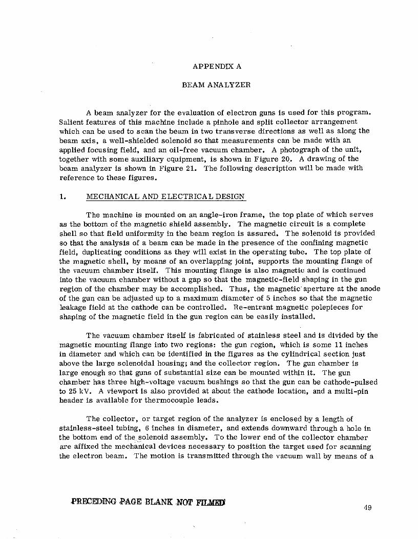
APPENDIX A
BEAM ANALYZER
A beam analyzer for the evaluation of electron guns is used for this program.
Salient features of this machine include a pinhole and split collector arrangement
which can be used to scan the beam in two transverse directions as well as along the
beam axis, a well-shielded solenoid so that measurements can be made with an
applied focusing field, and an oil-free vacuum chamber. A photograph of the unit,
together with some auxiliary equipment, is shown in Figure 20. A drawing of the
beam analyzer is shown in Figure 21. The following description will be made with
reference to these figures.
1. MECHANICAL AND ELECTRICAL DESIGN
The machine is mounted on an angle-iron frame, the top plate of which serves
as the bottom of the magnetic shield assembly. The magnetic circuit is a complete
shell so that field uniformity in the beam region is assured. The solenoid is provided
so that the analysis of a beam can be made in the presence of the confining magnetic
field, duplicating conditions as they will exist in the operating tube. The top plate of
the magnetic shell, by means of an overlapping joint, supports the mounting flange ofthe vacuum chamber itself. This mounting flange is also magnetic and is continued
into the vacuum chamber without a gap so that the magnetic-field shaping in the gun
region of the chamber may be accomplished. Thus, the magnetic aperture at the anode
of the gun can be adjusted up to a maximum diameter of 5 inches so that the magneticleakage field at the cathode can be controlled. Re-entrant magnetic polepieces forshaping of the magnetic field in the gun region can be easily installed.
The vacuum chamber itself is fabricated of stainless steel and is divided by the
magnetic mounting flange into two regions: the gun region, which is some 11 inchesin diameter and which can be identified in the figures as the cylindrical section justabove the large solenoidal housing; and the collector region. The gun chamber is
large enough so that guns of substantial size can be mounted within it. The gunchamber has three high-voltage vacuum bushings so that the gun can be cathode-pulsedto 25 kV. A viewport is also provided at about the cathode location, and a multi-pinheader is available for thermocouple leads.
The collector, or target region of the analyzer is enclosed by a length ofstainless-steel tubing, 6 inches in diameter, and extends downward through a hole inthe bottom end of the solenoid assembly. To the lower end of the collector chamberare affixed the mechanical devices necessary to position the target used for scanningthe electron beam. The motion is transmitted through the vacuum wall by means of a
PRECEDIING PAGE BLANK NOT FILM 49

Ar
44
Figure 20. Beam Analyzer and Auxiliary Equipment
50

SHOUSING EWPORT
// SION LES PTECE 0 I
FARADAY CAGE COLLECTOR
SOLENOID ANDMAGNETIC CIRCUIT- -OLCO SPOTPS
-O PS
PUMP VALVE LEAK VALVE
-5 -M ROR -
TUNG-STEN SCEE --- r-
COOLECONTROL
°ELLOWS
"AXIS SCREWS (31) -
S" ANDY"Y AXIS IORIVESCO FITTINGS (3
ELECTORIGINARON PAG] UNF POOR QUALIESS-STEE1
HOUSIG w I~P-m I I, VIEWPORT
IRON POLE PIECE--
MOLECULAR 33T;EN SCEEN IROSIEVE RlrP i UAW II l~
,FARADAY CAGE COLLECTOR
SOLENOID, ANI 14 ttt~ l ;\~X 4 R'1'
MAGNETIC CIRCIJ TCLETRSUP ORT POST
VIE PORT~d W
STUNGSTEN SCREENRLE"Z* XIS DRIVE
B)ELLOWS
VAXIS SOCREWS 3 --I
COAX FITTINS X"AD Y AI DIE
OOR,
Figure 21. Outline Drawing of the Beam Analyzer
RIGINAU PAGIO-1OF POOR QUALrML 51

bellows which allows some 8 inches of axial motion, and about 1 inch of motion ineither of the two transverse directions. Changes in the transverse position of thecollector assembly can be within 0. 001 inch. A motor drive for both transverse axesis used in combination with a recorder for automatic plotting of the output from thecollector.
Electrical observations of the beam are made with the use of a Faraday-cagecollector assembly. This assembly consists of a shielded split-collector locatedbehind an apertured molybdenum target which intercepts the major portion of the beam.By moving this pinhole collector throughout the beam, the current density distributionin the beam may be established. In addition, the division of current to the two halvesof the split collector is a measure of the transverse velocity distribution in the beam.
For visual observation of the beam, a tungsten mesh target can be rotated intothe beam. The beam image is reflected, by a system of two mirrors, through a view-port located at the bottom end of the chamber. A telescope located at this port makespossible a visual check on the beam size and shape under the influence of changingpotentials and magnetic fields. The same telescope is used for pyrometric measure-ments of the cathode temperature.
The pulses from the modulator used during tests of the gun are synchronizedto zero ac heater current in order to eliminate the effect of the magnetic field producedby the heater. Provisions are made for demagnetization of the solenoid frame tocreate a predictable na gnetic flux density in the gun region.
52

APPENDIX B
LIST OF SYMBOLS
a drift tube inner radius
b beam radius
c free-space velocity of light
E b dc beam voltage
Ef heater voltage
Ib dc beam current
Iby body current
If heater current
Imag focusing solenoid current
Saxial length
M cavity gap coupling coefficient
Pd rf drive power
P output powero
Q quality factor of resonant cavity
Q unloaded Q
Q external Q
QL total loaded Q
R/Q, Rsh cavity interaction gap shunt resistance
u dc beam velocity0
V de beam voltage
VSWR voltage standing wave ratio
Pe propagation factor associated with the dc beam velocitye(9 = /u )e 0
P q plasma propagation factor (3 =co q/u 1/2
y relativistic propagation factor (r = e[1 - (Uo/)2]
conversion efficiency
53

APPENDIX B (Cont.)
rf phase shift
w angular frequency
wq reduced plasma angular frequency
B magnetic field in gauss
54
DISTRIBUTION LIST NASA CR-134761February 1975
NATIONA L AERONAUTICS AND SPACE ADMINISTRATION
HeadquartersWashington, D.C. 20546Attention: SC/Dr. R. B. Marsten
REM/E. C. Buckley
NASA-Lewls Research Center21000 Brookpark Road
Cleveland, Ohio 44135Attention: H. W. Plohr (MIS 54-1)
R. E. Alexovich (MS 54-5)
F. E. Kavanagh (MS 54-5)
Dr. H. G. Kosmahl (MIS 54-5)
Technical Utilization Off. (NIS 3-19)
Contracts Section B
A. J. Doskocil (MS 54-1)Audit Branch (iMS 500-303)
NASA-George C. Marshall Space Flight CenterHuntsville, Alabama 35812Attention: E. C. Hamilton (RASRT-A)
General Electric Company Hughes Aircraft CompanyElectron Dynamics Division
Tube DepartmentMicrowave Tube Operations
Torrance, California 90509Schenectady, NY. 12305
Attention: Mr. D. Hawkins Attention: Mr. NI. KreismanisAttention: MIr. D. Hawkins
MIr. E.. LienJet Propulsion Laboratory
Varian Associates4800 Oak Grove Drive
611 Hansen WayPasadena, California 91103Attention: L. Derr Palo Alto, California 94304
Litton Industries D.F. BarberTube Division Chief Reliability Branch
960 Industrial Road Dept. of the Air Force
Griffiss AFB, New York 13440San Carlos, California 94070Attention: Larry Jones Dr. L. Lesensky
Dr. G. Haas Raytheon CompanyWaltham, Mass. 02154
Office of Naval ResearchDefense Department Dr. E. S. Rittner
Washington, D.C. 20390 Comsat Laboratories
NASA Scientific and Technical Clarksburg, Maryland 20743
Information Facility National Technical Information ServiceAttention: Acquisitions Branch Springfield, Virginia 22151 (40)P. O. Box 33College Park, Maryland 20740 (2)