AMIT SPINNING INDUSTRIES LIMITED - Bombay … SPINNING INDUSTRIES LIMITED Notice.
Design Considerations and Deployment Simulations of
Spinning Space Webs
Mattias Gardsback∗ and Gunnar Tibert†
KTH Mechanics, Royal Institute of Technology, SE-100 44 Stockholm, Sweden.
Dario Izzo‡
Advanced Concepts Team, EUI-ACT, ESTEC, Keplerlaan 1, 2201 AZ Noordwijk, The Netherlands.
ESA Advanced Concepts Team (ACT) has proposed to construct large space antennasand solar power systems by deploying and stabilising a large web in space. The ideaoriginates from the Japanese “Furoshiki Satellite”. Since an overly complicated controlsystem contributed to the partly chaotic deployment, ACT suggests to use centrifugalforces to deploy the space web.
In this study the design and folding pattern of space webs are discussed. An analyticalmodel and a finite element model used to describe the deployment, from the chosen folding,are presented. Free deployment of space webs is studied and a first control strategy thatenables controlled and stable deployment is suggested.
I. Introduction
Power generation (solar panels), propulsion (solar sails) and communication (antennas) are examples ofapplications in space that require large deployable structures. Space webs can be seen as an intermediate stepbetween todays rigid deployable structures and future deployable gossamer structures. The idea originatesfrom the Japanese “Furoshiki Satellite”.1–3 The space web is composed of a large membrane or net held intension by thruster controlled corner satellites or by spinning the whole assembly. An idea put forward byKaya et al.4 is to build up the antenna or solar power elements by robots that crawls on the web like spiders.
The difficulty in deploying a space web in a controlled manner was shown in the partly chaotic deploymentduring the Furoshiki experiment in January 2006.5 Thus, a deployment that is easier to control is desirable.ACT has investigated the possibilities to use centrifugal forces to deploy and stabilise the web in space.6,7
Deployment using centrifugal forces have many advantages, e.g., the control forces can be applied to thecentre hub, all the significant forces are in the plane of rotation, and both fast and slow deployment velocitiesare possible.
Large structures stabilised by centrifugal forces have been considered for space applications since the early1960s when Astro Research Corporation analysed several spin-stabilised structures,8–11 most notable is theHeliogyro solar sail by MacNeal,12 and similar spin-stabilised structures are still being considered for solarsail missions.13,14 In Japan, spinning concepts were considered for solar sails already in the mid 1980s,15 andrecently several concepts have been analysed and tested both on ground and in space.16–19 Nevertheless, theonly successful deployment and control of a large spin-stabilised space structure is the Russian Znamya-2experiment in 1993.20
Numerical studies have been performed on the spin-stabilisation of deployed space webs.7,21 In this studythe focus is on the deployment phase. An analytical model is developed inspired by deployment models ofcircular membranes.20,22 A finite element model is also implemented in LS-DYNA. The two models can beused to test important design parameters and control algorithms.
∗PhD Student, AIAA Student Member.†Research Associate, AIAA Member.‡Mission Analyst, AIAA Member.
1 of 10
American Institute of Aeronautics and Astronautics
(a)
(b)
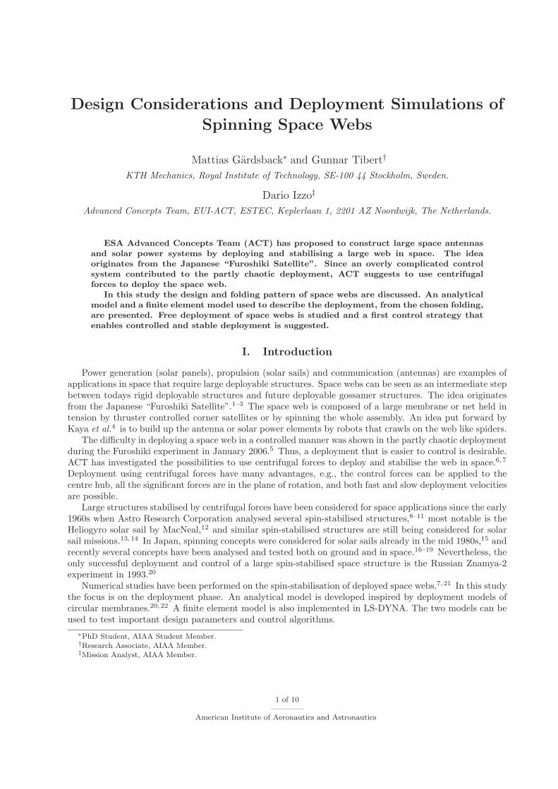
Jh = 12mhr2
0
Jc = 4mcr20
Jw = mwr20
Jh = 12mhr2
0
Jc = 2mcS2
Jw =16mwS2
r0S
S
Figure 1. Moment of inertia for the system: (a) before deployment and (b) after deployment.
II. Centrifugal force deployment
The use of centrifugal forces to deploy large structures in space is appealing for many reasons:
• Spinning satellites are used for many purposes already and small-scale testing can be performed onexisting satellites.
• The centrifugal force is always in the plane of rotation of the spinning satellite. Therefore, as long asthe rotational forces are dominating, the out-of-plane motion will be negligible.
• For centrifugal deployment, the control is relatively simple. Increased control requires more expensiveequipment, which also increases the risk of technical problems and unsuccessful deployment.
• Centrifugal force deployment can be either slow or fast, whichever leads to a controlled deployment.
A minimum of control is desirable, and preferably free deployment where the membrane or web is deployedfrom the initial rotation of the satellite without any control. However, two fundamental physical laws,the conservation of angular momentum and conservation of energy, makes this difficult. The total angularmomentum K must be constant, i.e.
K = J0ω0 = Jfωf (1)
where J is the moment of inertia, ω is the angular velocity of the system and indices 0 and f denotes theinitial and the final states, respectively. At the same time the energy E must be constant:
E =J0ω
20
2=
Jfω2f
2+ Esurplus (2)
Since the moment of inertia, Figure 1, and consequently the angular momentum, increases with the squareof the size of the deployed structure, from the small stowed size r0 to the much greater deployed side lengthS, the angular velocity must decrease at the same rate. For free deployment, this implies low final angularvelocities for very large structures, and that almost all the initial kinetic energy must be removed somehow.Otherwise, the surplus of energy will cause oscillations in the plane of rotation.
Webs also have a tendency to get entangled, but the risk of entanglement decreases substantially if thespace web is not coiled back on the central satellite. Hence, to obtain a successful centrifugal deployment ofa space web, the first task is to find a folding pattern and a robust control law that enable this.
III. Web design
Prior studies4,5 have not looked into the various choices of web geometry and mesh topology. Theprestress distribution in the web is not uniform due to the centrifugal force field and it is required that the
2 of 10
American Institute of Aeronautics and Astronautics
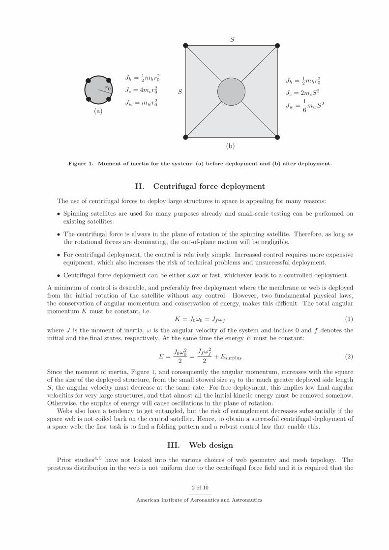
(a) n = 3, µ = 3 (b) n = 3, µ = 4 (c) n = 3, µ = 6
(d) n = 4, µ = 3 (e) n = 4, µ = 4 (f) n = 4, µ = 6
Figure 2. Possible web and mesh configurations for n = 3, 4 and µ = 3, 4, 6.
web is in tension everywhere. The prestress in the web provides the out-of-plane stiffness and that stiffnessmay depend on the choice of mesh topology. The spinning of the web and the low out-of-plane stiffness createundesirable dynamic phenomena, such as travelling waves and excess out-of-plane deformations, which affectthe performance of the web. Due to all these aspects, a thorough analysis is required to obtain an adequatedesign of the web.
Web material
The web should be manufactured from a very light, but strong and stiff material. As the Zylon� fibre hassuperior properties compared to other fibres,23,24 Zylon� is the preferred choice for manufacturing the spaceweb.6 However, like most high performance fibres, Zylon� suffers from strength degradation when exposedto light.23–25
Web geometry and topology
Six possible space web configurations with triangular, quadratic and hexagonal mesh topologies and threeand four corners, Figure 2, have been investigated.6 In terms of manufacturing, the most regular webconfigurations are:
• Triangular web and triangular mesh (TriTri).
• Triangular web and hexagonal mesh (TriHex).
• Quadratic web and quadratic mesh (QuadQuad).
The optimum layout of the web is determined by the following parameters: (i) prestressability (ii) manufac-turability, (iii) mass, (iv) out-of-plane stiffness and (v) eigenfrequencies, but not necessarily in that order.Analysis using the force method26,27 shows that only the quadratic mesh is prestressable by centrifugalforces.6 A quadratic web with a quadratic mesh is better from a manufacturing viewpoint and the out-of-plane stiffness and eigenfrequencies can be adjusted by the angular velocity and corner masses.6 Theremainder of this report will thus only be concerned with the quadratic web with a quadratic mesh.
It should be noted that Schuerch and Hedgepeth9 also chose a quadrangular mesh for their LOFT concept,although previous reports on the LOFT,10,28 used a triangular mesh. The reasons for finally choosing thesquare mesh over the triangular one were:9 (i) the shearing stiffness provided by the diagonal elements wasnot significantly greater than the stiffening effect derived from centrifugal forces; deleterious out-of-planemotions of the surface were reduced by deleting the diagonals, as vibrational energy then goes into theless harmful in-plane mode of deformation, (ii) the square mesh has the ability to undergo large shearingdeformations, without requiring in-plane strains or creases in the material; characteristics important forpackaging purposes.
3 of 10
American Institute of Aeronautics and Astronautics
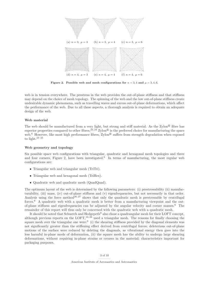
Figure 3. Complete star folding sequence for a quadratic sheet (note that not all lines are fold lines), andhub-wrapping folding of the star arms.
IV. Folding patterns for centrifugal deployment
Fundamental to a successful deployment is an appropriate folding pattern. Several folding patterns forlarge space structures have been proposed for various deployment approaches. A good example is the Miura-Ori29 for the efficient folding of square solar sails. Several studies have dealt with the folding of a circularsolar sail by wrapping it around a cylindrical hub.30–32 However, neither of these hub-wrapping schemes aresuitable for triangular or square sheets.
Schuerch and Hedgepeth9 suggested a folding pattern for the LOFT system where the supporting struc-ture is sheared to be folded into the hub. This pattern produces a star-like shape of the structure beingfolded. Melnikov and Koshelev20 proposed a similar pattern for the folding of spin-deployed circular spacestructures. A similar folding pattern was also used in the experimental and numerical study of solar saildeployment by Matunaga et al.16
The arms of the star can then be folded in various ways.20 Two approaches appear especially interestingdue to their simplicity: (i) folding of the arms in a zig-zag manner towards the hub or (ii) coiling the armsaround the hub as in the hub-wrapping concept.
In this study, the star pattern is preferred since it is relatively easy to control and model. For the samereasons the coiling of the arms around the hub is chosen.
V. Control
The control law should be selected so that the space web ends up in the desired configuration at the endof the deployment, within a required time period and with no undesirable oscillations or entanglement of thesystem. A prerequisite for a stable deployment is that the centrifugal force is much greater than the Coriolisand inertial forces.20
The deployment can be controlled in different ways. The control parameters could be the torque, M , thelength of the star arm, L, the angular velocity of the centre hub, ω, or the force that resists the deploymentof each segment, N .
Several, more or less successful, control strategies have been described in literature. Salama et al.13
linearly increase the angular velocity ω from 0 to ωmax during a time period of ∆t, and then keep it constantat ωmax, to deploy tethers in the first step of unfolding from a star folding. They assume that the structuraldamping is 5%.
Melnikov and Koshelev20 use the torque and the velocity of the cable being fed out as control parametersto deploy the Znamya-2 reflector. They propose increased torque as the angular velocity decreases, accordingto the law:
M = M0
(1 − ω
ω0
)(3)
where M0 is the initial momentum applied to the centre hub and ω0 is the initial angular velocity of the centrehub. Using this strategy, a high initial angular velocity, a low angular velocity in the end, short deploymenttime and a stable and smooth deployment without entanglement and coiling are obtained. Melnikov andKoshelev20 found that a higher value of the quotient M0/ω0 produces a more stable deployment. A refined
4 of 10
American Institute of Aeronautics and Astronautics
LR
r0
mc
O e(0)x
e(0)y
e(1)x
e(1)y
e(2)x
e(2)y ϕ1
ϕ2
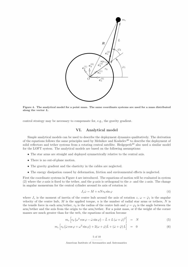
Figure 4. The analytical model for a point mass. The same coordinate systems are used for a mass distributedalong the vector L.
control strategy may be necessary to compensate for, e.g., the gravity gradient.
VI. Analytical model
Simple analytical models can be used to describe the deployment dynamics qualitatively. The derivationof the equations follows the same principles used by Melnikov and Koshelev20 to describe the deployment ofsolid reflectors and tether systems from a rotating central satellite. Hedgepeth22 also used a similar modelfor the LOFT system. The analytical models are based on the following assumptions:
• The star arms are straight and deployed symmetrically relative to the central axis.
• There is no out-of-plane motion.
• The gravity gradient and the elasticity in the cables are neglected.
• The energy dissipation caused by deformation, friction and environmental effects is neglected.
First the coordinate systems in Figure 4 are introduced. The equations of motion will be evaluated in system(2) where the x-axis is fixed to the tether, and the y-axis is orthogonal to the x- and the z-axis. The changein angular momentum for the central cylinder around its axis of rotation is:
Jzω = M + nNr0 sinϕ (4)
where Jz is the moment of inertia of the centre hub around the axis of rotation z, ω = ϕ1 is the angularvelocity of the centre hub, M is the applied torque, n is the number of radial star arms or tethers, N isthe tensile force in each arm/tether, r0 is the radius of the centre hub and ϕ = ϕ2 is the angle between thearm/tether and the axis from the origin to the arm/tether. For a point mass, or if the weight of the cornermasses are much greater than for the web, the equations of motion become
mc
[r0
(ω2 cos ϕ − ω sinϕ
) − L + L (ω + ϕ)2]
= N (5)
mc
[r0
(ω cos ϕ + ω2 sinϕ
)+ 2(ω + ϕ)L + (ω + ϕ) L
]= 0 (6)
5 of 10
American Institute of Aeronautics and Astronautics
where mc is the corner point mass and L is the current length of the tether/arm.Space webs folded into the star pattern can be described similarly. The deployment is performed in two
steps. The dynamics of the first step, the deployment of the star arms, is most important. When the armsare deployed, the corners are approximately in position. The deployment of the rest of the web does notinvolve so large changes in configuration and should not pose any major problems.20
The space web is first folded into n identical arms positioned symmetrically around the central hub. Thearms can be folded on spools at the end of the arms, in a zig-zag pattern, or coiled around the centre hub.The line density ρL of an arm varies linearly, from zero at the tip of the arm. If the arm is initially coiledaround the centre hub, the line density is given by
ρL =2mw
nH2(L − l) (0 ≤ l ≤ L) (7)
where mw is the mass of the web and H is the length of the arm. The resulting equations of motion become
2mw
nH2
[L2
2
(r0
(ω2 cos ϕ − ω sin ϕ
) − L)
+L3
6(ω + ϕ)2
]= N (8a)
r0
(ω cos ϕ + ω2 sinϕ
)+ 2(ω + ϕ)L +
L
3(ω + ϕ) = 0 (8b)
To simulate space webs that are coiled around the centre hub, the following variable substitutions aremade: ω = ω + ϕ, L = L − r0 max
(0, |ϕ| − π
2
), L = ∓r0ϕ, L = ∓r0ϕ and ϕ ± max
(|ϕ|, π2
). Equations for
many other deployment schemes can be derived similarly.6
VII. Finite element model
A finite element model including a centre hub, a space web and corner masses has been implemented.The node and element geometry and connectivity are generated in MATLAB. The equations of motion arethen solved in LS-DYNA33 using the explicit central difference integration method. The main differencescompared to the analytical model is that perturbations can be studied, the cables can store elastic energyand the arms are not necessarily straight during the deployment.
The centre hub is modelled as a rigid body since the modelling of the coiling of the web around the centrehub is crucial. Contrary, in the corners point masses are sufficiently accurate. The cables and tethers aremodelled with a great number of cable elements, i.e. truss elements with a no-compression material.
The contact between the cables and the rigid bodies, at the centre, was modelled using the kinematicconstraint method.34 It is not obvious how to coil the web near the hub and include contact initially.Therefore, initial contact between cable elements in the space web were disregarded, since higher prioritywas given to coil the space web as close to the centre hub as possible.
VIII. Results
Deployment of coiled star folded web
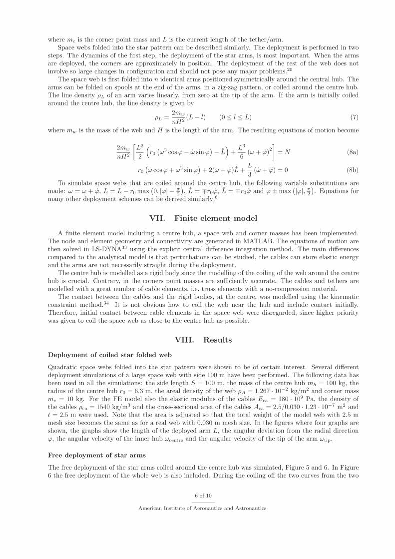
Quadratic space webs folded into the star pattern were shown to be of certain interest. Several differentdeployment simulations of a large space web with side 100 m have been performed. The following data hasbeen used in all the simulations: the side length S = 100 m, the mass of the centre hub mh = 100 kg, theradius of the centre hub r0 = 6.3 m, the areal density of the web ρA = 1.267 · 10−2 kg/m2 and corner massmc = 10 kg. For the FE model also the elastic modulus of the cables Eca = 180 · 109 Pa, the density ofthe cables ρca = 1540 kg/m3 and the cross-sectional area of the cables Aca = 2.5/0.030 · 1.23 · 10−7 m2 andt = 2.5 m were used. Note that the area is adjusted so that the total weight of the model web with 2.5 mmesh size becomes the same as for a real web with 0.030 m mesh size. In the figures where four graphs areshown, the graphs show the length of the deployed arm L, the angular deviation from the radial directionϕ, the angular velocity of the inner hub ωcentre and the angular velocity of the tip of the arm ωtip.
Free deployment of star arms
The free deployment of the star arms coiled around the centre hub was simulated, Figure 5 and 6. In Figure6 the free deployment of the whole web is also included. During the coiling off the two curves from the two
6 of 10
American Institute of Aeronautics and Astronautics
(a) t=0 s (b) t=0.2 (c) t=0.4
(d) t=0.6 (e) t=0.8 (f) t=1.0
Figure 5. Free deployment of space web.
0 0.2 0.4 0.6 0.8 1 1.2
−20
0
20
0 0.2 0.4 0.6 0.8 1 1.2
0
20
40
t
AnalyticalFinite Element (arms)Finite Element (web)
0 0.2 0.4 0.6 0.8 1 1.20
20
40
0 0.2 0.4 0.6 0.8 1 1.2−10
−5
0
5
10
L(m
)ϕ
(rad)
ωcentr
e(r
ad/s)
ωti
p(r
ad/s)
Figure 6. Free deployment of space web.
different deployments almost coincide. The deployment is initiated by an initial rotational velocity of 8πrad/s on the hub and the web. The star arms are coiled off from the hub, but then coiled on the centre hubagain. The agreement between the two models is rather good for the length of the deployed arm, but notfor the rotational velocities because the arms are not straight in the FE model.
Controlled deployment of star arms
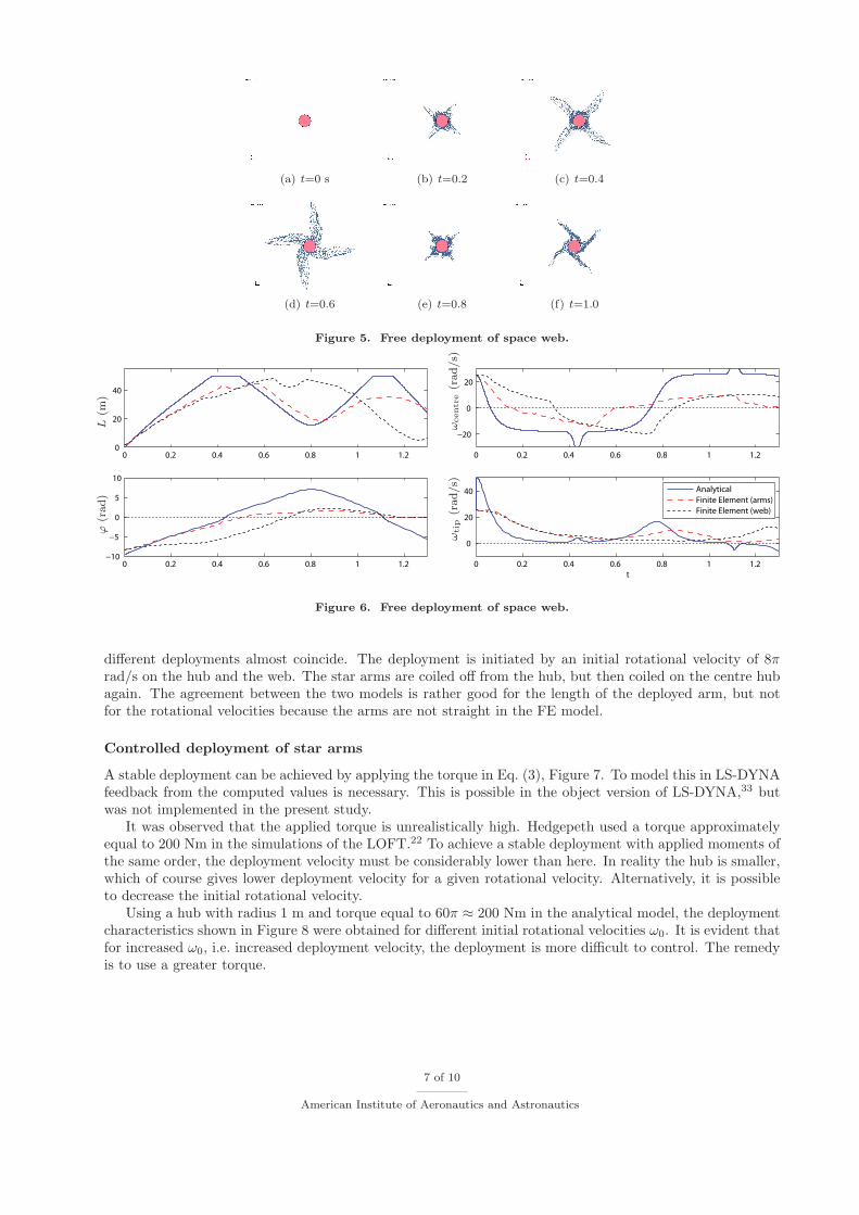
A stable deployment can be achieved by applying the torque in Eq. (3), Figure 7. To model this in LS-DYNAfeedback from the computed values is necessary. This is possible in the object version of LS-DYNA,33 butwas not implemented in the present study.
It was observed that the applied torque is unrealistically high. Hedgepeth used a torque approximatelyequal to 200 Nm in the simulations of the LOFT.22 To achieve a stable deployment with applied moments ofthe same order, the deployment velocity must be considerably lower than here. In reality the hub is smaller,which of course gives lower deployment velocity for a given rotational velocity. Alternatively, it is possibleto decrease the initial rotational velocity.
Using a hub with radius 1 m and torque equal to 60π ≈ 200 Nm in the analytical model, the deploymentcharacteristics shown in Figure 8 were obtained for different initial rotational velocities ω0. It is evident thatfor increased ω0, i.e. increased deployment velocity, the deployment is more difficult to control. The remedyis to use a greater torque.
7 of 10
American Institute of Aeronautics and Astronautics
0 0.5 1 1.5 2 2.5 30
10
20
30
0 0.5 1 1.5 2 2.5 30
10
20
30
40
50
t
0 0.5 1 1.5 2 2.5 30
20
40
0 0.5 1 1.5 2 2.5 3−10
−5
0
L(m
)ϕ
(rad)
ωcentr
e(r
ad/s)
ωti
p(r
ad/s)
Figure 7. Deployment of space web using the control law in Eq. (3) with M0 = ω0 · 105.
50 100 150 200 250 300
−5
0
5
10
50 100 150 200 250
−4
−2
0
2
4
t
0 50 100 150 200 250 3000
20
40
60
0 50 100 150 200 250 300−100
−50
0
50
ω0
=π/2
ω0
=2π
ω0
=8π
L(m
)ϕ
(rad)
ωcentr
e(r
ad/s)
ωti
p(r
ad/s)
Figure 8. Deployment of the star arms. A torque is applied according to the control law in Eq. (3) withM0 = 60π Nm and ω0 = π/2, 2π, 8π rad/s.
Rotational velocity according to Salama et al.
Salama et al.13 propose linearly increasing angular velocity of the inner hub, from 0 at time t = 0 to ωmax
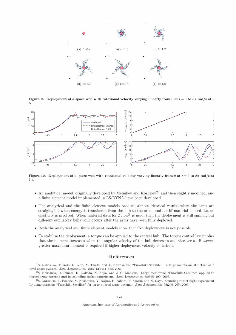
at time t = ∆t, and then keep the angular velocity constant at ωmax. There is no systematic way to choosethese parameters, but use of the values ωmax = 8π rad/s and ∆t = 2 s,13 resulted in the deployment inFigures 9 and 10. The arms are coiled off the centre hub, and not coiled back on the hub again. However,there are undesirable oscillations in the plane of rotation.
This example was also used to validate the analytical model. When a material that is 1000 times stifferthan Zylon� is used, the results from the analytical and finite element models are almost identical.
IX. Conclusions
The main conclusions from the present study are:
• Only a web with a quadratic mesh topology can be adequately prestressed by spinning.
• The star folding pattern makes it possible to deploy the web in two distinctive stages to achieve bettercontrol.
• The star folding pattern is advantageous from a modelling point of view since it can be described withsimple equations.
• For the second deployment stage, coiling the arms around the hub was chosen in favour of a radialzig-zag scheme. The coiling scheme does not require additional tethers to control the deployment rateof the star arms, which is required in the zig-zag scheme.
8 of 10
American Institute of Aeronautics and Astronautics
(a) t=0 s (b) t=1.0 (c) t=1.2
(d) t=1.4 (e) t=1.6 (f) t=1.8
Figure 9. Deployment of a space web with rotational velocity varying linearly from 0 at t = 0 to 8π rad/s at 2s.
0 0.5 1 1.5 2 2.5 30
5
10
15
20
25
0 0.5 1 1.5 2 2.5 30
10
20
30
40
50
t
0 0.5 1 1.5 2 2.5 30
20
40
60
0 0.5 1 1.5 2 2.5 3−10
−5
0
AnalyticalFinite Element (elastic)Finite Element (stiff)
L(m
)ϕ
(rad)
ωcentr
e(r
ad/s)
ωti
p(r
ad/s)
Figure 10. Deployment of a space web with rotational velocity varying linearly from 0 at t = 0 to 8π rad/s at2 s.
• An analytical model, originally developed by Melnikov and Koshelev20 and then slightly modified, anda finite element model implemented in LS-DYNA have been developed.
• The analytical and the finite element models produce almost identical results when the arms arestraight, i.e. when energy is transferred from the hub to the arms, and a stiff material is used, i.e. noelasticity is involved. When material data for Zylon� is used, then the deployment is still similar, butdifferent oscillatory behaviour occurs after the arms have been fully deployed.
• Both the analytical and finite element models show that free deployment is not possible.
• To stabilise the deployment, a torque can be applied to the central hub. The torque control law impliesthat the moment increases when the angular velocity of the hub decreases and vice versa. However,greater maximum moment is required if higher deployment velocity is desired.
References
1S. Nakasuka, T. Aoki, I. Ikeda, Y. Tsuda, and Y. Kawakatsu. “Furoshiki Satellite”—a large membrane structure as anovel space system. Acta Astronautica, 48(5–12):461–468, 2001.
2S. Nakasuka, R. Funase, K. Nakada, N. Kaya, and J. C. Mankins. Large membrane “Furoshiki Satellite” applied tophased array antenna and its sounding rocket experiment. Acta Astronautica, 58:395–400, 2006.
3S. Nakasuka, T. Funane, Y. Nakamura, Y. Nojira, H. Sahara, F. Sasaki, and N. Kaya. Sounding rocket flight experimentfor demonstrating “Furoshiki Satellite” for large phased array antenna. Acta Astronautica, 59:200–205, 2006.
9 of 10
American Institute of Aeronautics and Astronautics
4N. Kaya, M. Iwashita, S. Nakasuka, L. Summerer, and J. Mankins. Crawling robots on large web in rocket experimenton Furoshiki deployment. In Proc. 55th Int. Astronomical Congress, Vancouver, Canada, 4–8 October 2004. IAC-04-R3.
5S. Nakasuka and N. Kaya. Quick release on experiment results of mesh deployment and phased array antenna by S-310-36,September 4 2006. Online Internet: http://www.isas.ac.jp/e/forefront/2006/nakasuka/.
6G. Tibert and M. Gardsback. Space webs, final report. Technical report, ESA, 2006. Ariadna ID: 05/4109, ContractNumber: 19702/06/NL/HE.
7D. McKenzie, M. Cartmell, G. Radice, and M. Vasile. Space webs, final report. Technical report, ESA, 2006. AriadnaID: 05/4109, Contract Number: 4919/05/NL/HE.
8H. U. Schuerch and R. MacNeal. Deployable centrifugally stabilized structures for atmospheric entry from space. NASAContractor Report, NASA CR-69, July 1964.
9H. U. Schuerch and J. M. Hedgepeth. Large low-frequency orbiting radio telescope. NASA Contractor Report, NASACR-1201, October 1968.
10W. M. Robbins, Jr. The feasibility of an orbiting 1500-meter radio telescope. NASA CR-792, Astro Research Corporation,1967.
11A. C. Kyser. Uniform-stress spinning filamentary disk. AIAA Journal, 3(7):1313–1316, 1965.12R. H. MacNeal. The Heliogyro: an interplanetary flying machine. Astro Research Corporation, ARC-R-249, March 1967.13M. Salama, C. White, and R. Leland. Ground demonstration of a spinning solar sail deployment concept. Journal of
Spacecraft and Rockets, 40(1):9–14, 2003.14R. L. Burton, V. L. Coverstone, J. Hargens-Rysanek, K. M. Ertmer, T. Botter, G. Benavides, B. Woo, D. L. Carroll, P. A.
Gierow, G. Farmer, and J. Cardin. UltraSail — ultra-lightweight solar sail concept. In Proc. 41st AIAA/ASME/SAE/ASEEJoint Propulsion Conf., Tucson, AZ, USA, July 10–13 2005. AIAA-2005-4117.
15J. Mitsugi, M. Natori, and K. Miura. Preliminary evaluation of the spinning solar sail. In Proc. 28thAIAA/ASME/ASCE/AHS/ASC Structures, Structural Dynamics, and Materials Conf., Monterey, CA, USA, April 1987.AIAA-1987-742.
16S. Matunaga, H. Yabe, K. Nakaya, M. Iai, K. Omagari, and O. Mori. Membrane deployment for spinning formation-flightsolar sail. In Proc. 14th Workshop on Astrodynamics and Flight Mechanics, Tokyo, July 26–27 2004. Paper A-11.
17O. Mori, Y. Tsuda, Y. Nishimura, and J. Kawaguchi. Deployment dynamics of clover type solar sail. In Proc. 14thWorkshop on Astrodynamics and Flight Mechanics, Tokyo, July 26–27 2004. Paper A-5.
18S. Masumoto, K. Omagari, T. Yamanaka, and S. Matunaga. System configuration of tethered spinning solar sail fororbital experiment: numerical simulation and ground experiment. In Proc. 25th International Symposium on Space Technologyand Science (ISTS), Kanazawa City, Japan, June 4–11 2006. Paper D-21.
19Y. Tsuda, K. Nakaya, O. Mori, and T. Yamamoto. Microsatellite-class solar sail demonstrator — mission design anddevelopment status. In Proc. 25th International Symposium on Space Technology and Science (ISTS), Kanazawa City, Japan,June 4–11 2006. Paper K-37.
20V. M. Melnikov and V. A. Koshelev. Large space structures formed by centrifugal forces, volume 4 of Earth Space InstituteBook Series. Gordon and Breach Science Publishers, India, 1998.
21G. B. Palmerini, S. Sgubini, and M. Sabatini. Space webs based on rotating tethered formations. Valencia, Spain, 2006.57th International Astronautical Congress, 2–6th October.
22J. M. Hedgepeth. Dynamics of a large spin-stiffened deployable paraboloidal antenna. Journal of Spacecraft and Rockets,7(9):1043–1048, 1970.
23L. G. Seely, M. Zimmerman, and J. McLaughlin. The use of Zylon fibers in ULDB tendons. Advances in Space Research,33:1736–1740, 2004.
24J. W. S. Hearle, editor. High-performance fibers. Woodhead publishing, Cambridge, UK, 2001.25K. A. Gittemeier, C. W. Hawk, M. M. Finckenor, and E. Watts. Space environmental effects on coated tether materials.
In Proc. 41st AIAA/ASME/SAE/ASEE Joint Propulsion Conf., Tucson, AZ, USA, 10–13 July 2005. AIAA-2005-4433.26S. Pellegrino. Structural computations with the singular value decomposition of the equilibrium matrix. International
Journal of Solids and Structures, 30(21):3025–3035, 1993.27G. Tibert. Deployable Tensegrity Structures for Space Applications. PhD thesis, Royal Institute of Technology, Stockholm,
Sweden, 2002.28W. M. Robbins, Jr. Spinning paraboloidal tension networks. NASA CR-873, Astro Research Corporation, 1967.29K. Miura. Method of packaging and deployment of large membranes in space. In Proc. 31st Int. Astronautical Congress,
Tokyo, 21–28 September 1980. IAF-80-A31.30S. D. Guest and S. Pellegrino. Inextensional wrapping of flat membranes. In R. Motro and T. Wester, editors, Proc. 1st
Int. Conf. on Structural Morphology, pages 203–215, Montpellier, France, 7–11 September 1992.31H. W. Scheel. Space-saving storage of flexible sheets. United States Patent, US 3,848,821, November 19, 1974.32H. Furuya, Y. Inoue, and T. Masuoka. Concept and deployment characteristics of rotationally skew fold membrane for
spinning solar sail. In Proc. 14th Workshop on Astrodynamics and Flight Mechanics, Tokyo, July 26–27 2004. Paper A-3.33Livermore software technology corporation, Livermore, CA, USA. LS-DYNA Keyword user’s manual, version 970, April
2003.34T.J.R. Hughes, R.L. Taylor, J.L. Sackman, A.C. Curnier, and W. Kanoknukulchai. A finite element method for a class
of contact-impact problems. Comput. Methods Appl. Mech. Engrg., 8:249–276, 1976.
10 of 10
American Institute of Aeronautics and Astronautics


![Deployment Control of Spinning Space Webs and Membranes126605/FULLTEXT03.pdfments and ”Furoshiki”-type approaches. The original Furoshiki concept is taking ... [150], which was](https://static.fdocuments.in/doc/165x107/5f96641de9b6cf41977085d3/deployment-control-of-spinning-space-webs-and-126605fulltext03pdf-ments-and-afuroshikia-type.jpg)