Industrial Fiber Optic Networking Industrial Fiber Optic Networking
Design Choices in Fiber OpticITS Telecommunications Networks
Michael H. ChawnerPresident & CEO
iMPath Networks Inc.65 Auriga DriveNepean, Ontario
K2H 5J9Tel: 1-613-226-4000 ext. 370
Dan Parsons, P. Eng.Product Manager
iMPath Networks Inc.65 Auriga DriveNepean, Ontario
K2H 5J9Tel: 1-613-226-4000 ext. 232
2
TABLE OF CONTENTS
ABSTRACT ......................................................................................................................................................... 3
DEVELOPING A SET OF CRITERIA FOR YOUR ITS COMMUNICATIONS NETWORK ....................... 3
QUALITY OF SERVICE (QOS)................................................................................................................................ 4RELIABILITY AND AVAILABILITY......................................................................................................................... 4MAINTAINABILITY .............................................................................................................................................. 5SCALABILITY ...................................................................................................................................................... 5COST .................................................................................................................................................................. 5STANDARDS COMPLIANCE ................................................................................................................................... 6
NETWORK DESIGN OPTIONS ........................................................................................................................ 7
SEPARATE VIDEO AND DATA/VOICE NETWORKS .................................................................................................. 7Separate CCTV and T1 Network Solutions ...................................................................................................... 7CCTV and SONET........................................................................................................................................ 10
INTEGRATED NETWORK SOLUTIONS .................................................................................................................. 12CCTV with T1 Transport .............................................................................................................................. 12Digital Video over SONET............................................................................................................................ 14The Hybrid CCTV/SONET Network .............................................................................................................. 17
NETWORK DESIGN COMPARISONS........................................................................................................... 19
ANALYSIS OF COST COMPARISONS .................................................................................................................... 20
CONCLUSION .................................................................................................................................................. 25

3
ABSTRACT
Designing a fiber optic communications network for Intelligent Transportation Systems (ITS)can be an overwhelming responsibility for decision-makers without previous experience in thefield of communications network design. There are nonetheless basic guidelines which, iffollowed, can help to ensure that the proper choices are made in assessing and selecting theappropriate network design. The following paper proposes a basic framework with guidelinesthat serve to facilitate fiber optic communications network design for traffic engineers and end-users. The three key elements of this framework can be summarized as follows:
• Developing a set of criteria that must be addressed by the chosen fiber optic communicationsnetwork design; and
• Understanding the basic network design architecture options available;
• Selecting the network architecture that best addresses the established list of criteria.
This paper addresses each of these elements in turn.
DEVELOPING A SET OF CRITERIA FOR YOUR ITS COMMUNICATIONSNETWORK
The first step towards selecting an appropriate network design involves understanding bothcurrent and future demands that will be made of the network. The requirements of a network arefundamentally driven by the ITS Services that will deployed over the infrastructure. Forexample, Variable Message Signs (VMS), Traffic Loop Counters, and Video SurveillanceCameras with Pan, Tilt and Zoom (PTZ) control represent possible ITS Services to be deployedin a network. Although no two ITS projects are likely to have exactly the same requirements,there is a common set of characteristics that one can identify for networks and their services thathelp clarify design goals. These characteristics are listed as follows:
• Quality of Service (QoS)• Reliability and Availability• Maintainability• Scalability and Fiber Efficiency• Cost• Standards Compliance
These characteristics are not independent of one another and trade-offs are invariably madebetween them. For example, a higher QoS typically results in higher costs, thereby making it

4
difficult to achieve a network with a low cost per video channel. As such, it is critical tounderstand which characteristics will take precedence in priority and which trade-offs are mostacceptable.
Quality of Service (QoS)ITS services such as Variable Message Signs (VMS), Traffic Loop Counters and Pan/Tilt/Zoom(PTZ) control of video surveillance cameras are accomplished through communicationsequipment found by the roadside. This equipment typically communicates with the TrafficControl Center through low speed, asynchronous data communications requiring data speeds ofaround 9600 bits per second (bps). Video surveillance equipment, on the other hand, requires amuch larger “pipe” to effectively transfer video signals back to the Traffic Control Center. Thesize of the “pipe”, or the communications bandwidth required per video camera signal, directlyaffects the quality of the video signal seen back at the Control Center. The quality of theseimages can be critical (particularly in times of inclement weather) in emergency situationsrequiring specific action under visibly identifiable circumstances (e.g., instructing the dispatch ofAmbulance services if deemed necessary, etc.). This need is further compounded during harshweather conditions in which visibility is somewhat blurred. Thus, in general, the Quality ofService required will be high for video surveillance. This requires that all communicationsequipment between the camera and the Traffic Control Center conform to an acceptablespecification (e.g., EIA/TIA 250C Medium Haul video quality specification) that will implicitlydictate the quality of the image at the Traffic Control Center. A similar analysis is required forevery piece of terminal equipment in the network representing a specific ITS Service so that theQuality of Service is understood for each service.
Reliability and AvailabilityReliability refers to how often a single piece of equipment fails, whereas availability refers tohow often the overall network solution fails to achieve its intended use. For example, all thecomponents of a fiber optic multiplexer may function well without breaking down (reliability).By designing a redundant fiber optic transmitter into the multiplexer, however, even if theprimary transmitter should fail, the network continues to remain available by virtue of theredundant transmitter, thereby maximizing network availability.
In any given ITS project, reliability and availability are fundamental requirements sinceequipment that is problematic can endanger the public’s safety. The availability of roadsideemergency telephone service, for example, needs to equal that of emergency 9-1-1 telephoneservice. Similarly, a network that is out of operation frequently does not allow personnel back atthe Traffic Control Center to dispatch ambulance services in a timely fashion in the event ofserious accident. A praiseworthy communications network design is ensured by (a) selectingequipment that has a proven track record of reliability in harsh environments; (b) selecting
5
equipment for which the calculated Mean Time Between Failures (MTBF) and Mean Time toRepair (MTTR) meet or exceed that required by network administrators; and (c) designingavailability into the network. The latter can be accomplished, for example, by having redundantcommunication links back to the Traffic Control Center in the event of a primary link failure.
MaintainabilityAn ITS network, by its very nature, is a Wide Area Network (WAN) that typically covers a largearea. Due to its expansive nature coupled with the need to repair problems very quickly, ease ofmaintenance is essential. The most common solution to this problem is computer-based NetworkManagement Systems (NMS) that can remotely monitor and configure the communicationsnetwork equipment from the Traffic Control Center. The effectiveness of an NMS will dependon how far into the network the NMS capabilities extend. Ideally, the NMS should extend itsreach right out to the “edge” of the network. Beyond network management, however, it isimportant to keep the complexity of the design and the amount of equipment required to aminimum, thereby minimizing the effects of equipment failures on the network.
ScalabilityRelative to other industries, ITS today remains in its infancy, though momentum in deployingservices is increasing at a significant rate. As such, a competent ITS communications networkdesign will take into account the need for future growth, or “scalability”, as the number of ITSServices deployed over the available communications infrastructure will undoubtedly increaseover time. Scalability in a communications network design manifests itself in two ways. Firstly,the design should incorporate modular communications equipment that can havecommunications bandwidth added as the need arises. Secondly, regardless of the number offibers available to the designer, the design should attempt to minimize the use of fibers. This isbecause dark fibers (i.e., fibers not used but available) can be used in future expansions forpurposes not yet apparent.
CostCost-effectiveness is a primary consideration of most end-users. As such, it is critical to strikeup a balance between the other criteria and cost, so as not to compromise the network designwhile keeping it affordable. Many network designs largely overlook other criteria in the interestof finding the lowest-cost solution. This results in networks that are often unreliable and verydifficult to scale to accommodate future growth. Equally important is the need to consider thelife-cycle costs of maintaining a network. These costs are directly related to two implementationissues. The first is the quality of the installed equipment. Problematic equipment requiresexpensive maintenance work. Often the equipment must be replaced, reversing any cost savingsrealized in the initial purchase. The second issue that affects maintenance costs is the inclusion of

6
a Network Management System in the initial installation. Network Management Systems musthave the capacity to remotely monitor and configure the deployed communications equipment.This is particularly important in view of the fact that the annual cost of maintaining anunmanaged network will range from 10% to 15% of the deployment cost of the network.
Standards ComplianceTransportation agencies hope that the systems they deploy will be capable of exchanginginformation with networks deployed by others. As such, adherence to industry-recognizedstandards is necessary. The NTCIP, or National Transportation Communications for ITSProtocol, is being developed to ensure that inter-network connectivity is through industrystandard interfaces, even if proprietary communications are used within an ITS network.
In addition to NTCIP, it is important for all equipment to meet prevalent standards for safety andEMI interference (FCC, etc). This will ensure that the equipment is safe for use by networkadministrators and is unlikely to cause failures in other equipment installed alongside it.

7
NETWORK DESIGN OPTIONS
The second component of the network architecture assessment framework involvesunderstanding the technological choices available in implementing a fiber optic network. Forillustrative purposes, we will consider different network design options for implementing anetwork consisting of the following elements:
• 100 video cameras with PTZ (20 cameras feeding into each of 5 remote multiplexers);• 200 traffic loop counters (data);• 50 ramp meters (data);• 25 emergency telephone lines (voice);• 50 Variable Message Signs (VMS) (data);• 5 Highway Advisory Radio (HAR) channels (voice);
Five generic network design options will be considered. These are as follows:1. Separate Video and Voice/Data Networks
• CCTV and T1• CCTV and SONET
2. Integrated Networks for Video, Voice and Data transmission (over a unified path)• CCTV and T1• Digital Video over SONET• Hybrid CCTV/SONET
Separate Video and Data/Voice NetworksA conventional approach to ITS network design is to deploy video on a separate network fromthat used to transport voice and data. Older networks simply used point-to-point videotransmission equipment to carry one channel of video all the way back to the Traffic ControlCenter on one fiber. This was extremely wasteful of the tremendous bandwidth available onfiber and was very difficult to scale. As such, point-to-point video multiplexing equipment thatcombines several signals onto one fiber is used. Data and voice communication is typicallythrough point-to-point T1 channel banks (and/or T1 carried on fault-tolerant SONET[Synchronous Optical NETworks] or SONET-like rings).
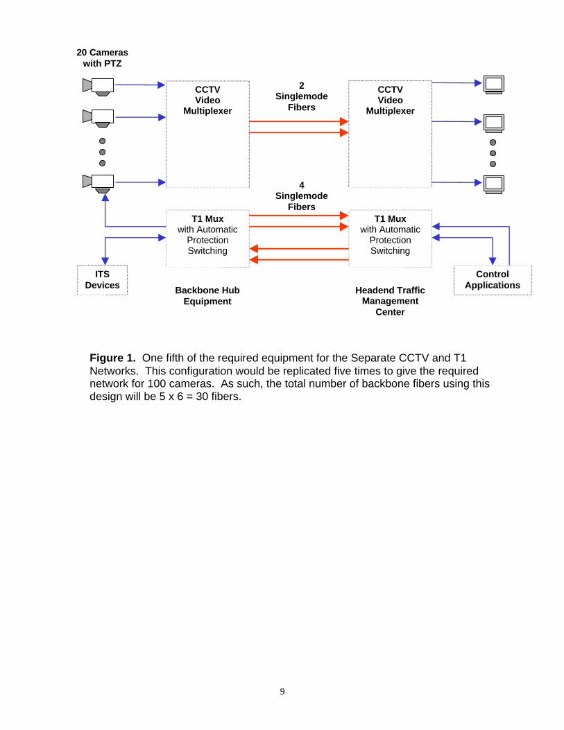
Separate CCTV and T1 Network SolutionsA traditional point-to-point CCTV and T1 approach using multiplexers to concentrate video anddata signals is illustrated in Figure 1. The T1 channel banks are equipped with low speed dataand voice interfaces, and integrate all such low-speed signals into a standard, electrical T1 signalat 1.544 Mbps. The CCTV video communications equipment is distinct from the digital T1
8
equipment and generally uses a network of proprietary analogue Frequency DivisionMultiplexing (FDM) technology over fiber optic cable due to the high bandwidth andtransmission distance requirements. Transmission redundancy is usually built into the videocommunications equipment. T1 channel banks for data and voice are usually not equipped fortransmission redundancy and will generally require external T1 Automatic Protection Switch(APS) equipment. CCTV video multiplexers traditionally provide the best video quality(broadcast quality) for the lowest price.
The multiplexed video signal that arrives at the Traffic Control Center feeds into a demultiplexerto recover the composite signal. The resulting individual video signals are fed into a videomatrix switch for distribution to the appropriate video monitors. As the network grows, the videoswitch becomes a bottleneck since the number of video sources may eventually exceed thecapacity of the switch. For network expansion, more physical fibers are required between theremote video multiplexers and the Traffic Control Center. This can be unbearably expensive insituations where additional fiber plant must be put into the ground. Network expansion costs canbe significantly eased if the video concentration multiplexers are modular and can have a highnumber of video channels integrated as required.
9
20 Cameraswith PTZ
ITSDevices
T1 Muxwith Automatic
ProtectionSwitching
CCTVVideo
Multiplexer
CCTVVideo
Multiplexer
T1 Muxwith Automatic
ProtectionSwitching
ControlApplications
2Singlemode
Fibers
4Singlemode
Fibers
Backbone HubEquipment
Headend TrafficManagement
Center
Figure 1. One fifth of the required equipment for the Separate CCTV and T1Networks. This configuration would be replicated five times to give the requirednetwork for 100 cameras. As such, the total number of backbone fibers using thisdesign will be 5 x 6 = 30 fibers.
10
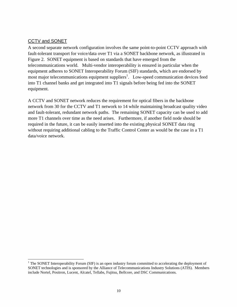
CCTV and SONETA second separate network configuration involves the same point-to-point CCTV approach withfault-tolerant transport for voice/data over T1 via a SONET backbone network, as illustrated inFigure 2. SONET equipment is based on standards that have emerged from thetelecommunications world. Multi-vendor interoperability is ensured in particular when theequipment adheres to SONET Interoperability Forum (SIF) standards, which are endorsed bymost major telecommunications equipment suppliers1. Low-speed communication devices feedinto T1 channel banks and get integrated into T1 signals before being fed into the SONETequipment.
A CCTV and SONET network reduces the requirement for optical fibers in the backbonenetwork from 30 for the CCTV and T1 network to 14 while maintaining broadcast quality videoand fault-tolerant, redundant network paths. The remaining SONET capacity can be used to addmore T1 channels over time as the need arises. Furthermore, if another field node should berequired in the future, it can be easily inserted into the existing physical SONET data ringwithout requiring additional cabling to the Traffic Control Center as would be the case in a T1data/voice network.
1 The SONET Interoperability Forum (SIF) is an open industry forum committed to accelerating the deployment ofSONET technologies and is sponsored by the Alliance of Telecommunications Industry Solutions (ATIS). Membersinclude Nortel, Positron, Lucent, Alcatel, Tellabs, Fujitsu, Bellcore, and DSC Communications.
11
20 Cameraswith PTZ
ITSDevices
T1 Muxwith Automatic
ProtectionSwitching
CCTVVideo
Multiplexer
SONET (SDH)Mux
CCTVVideo
Multiplexer
T1 Muxwith Automatic
ProtectionSwitching
ControlApplications
SONET (SDH)Mux
SONET (SDH)Mux
SONET (SDH)Mux
SONET (SDH)Mux
SONET (SDH)Mux
Traffic Management Facility
2Singlemode
Fibers
Figure 2. One fifth of the required equipment for the Separate CCTV network andentire SONET network is shown above. The video communications network would bereplicated five times to give the network required for 100 cameras. As such, the totalnumber of backbone fibers using this design will be (5 x 2 fibers per CCTV node) + (4fibers for SONET ring) = 14 fibers.
4Singlemode
Fibers
12
Integrated Network SolutionsIntegrated network solutions for video, voice and data are attractive due to the efficient use ofavailable optical fibers in the backbone segment of the network. This is particularlyadvantageous where the number of fibers installed in the ground is limited. In general, althoughusing one path for video, voice and data is ideal, it is important to keep in mind the effects oncost and Quality of Service for each specific configuration.
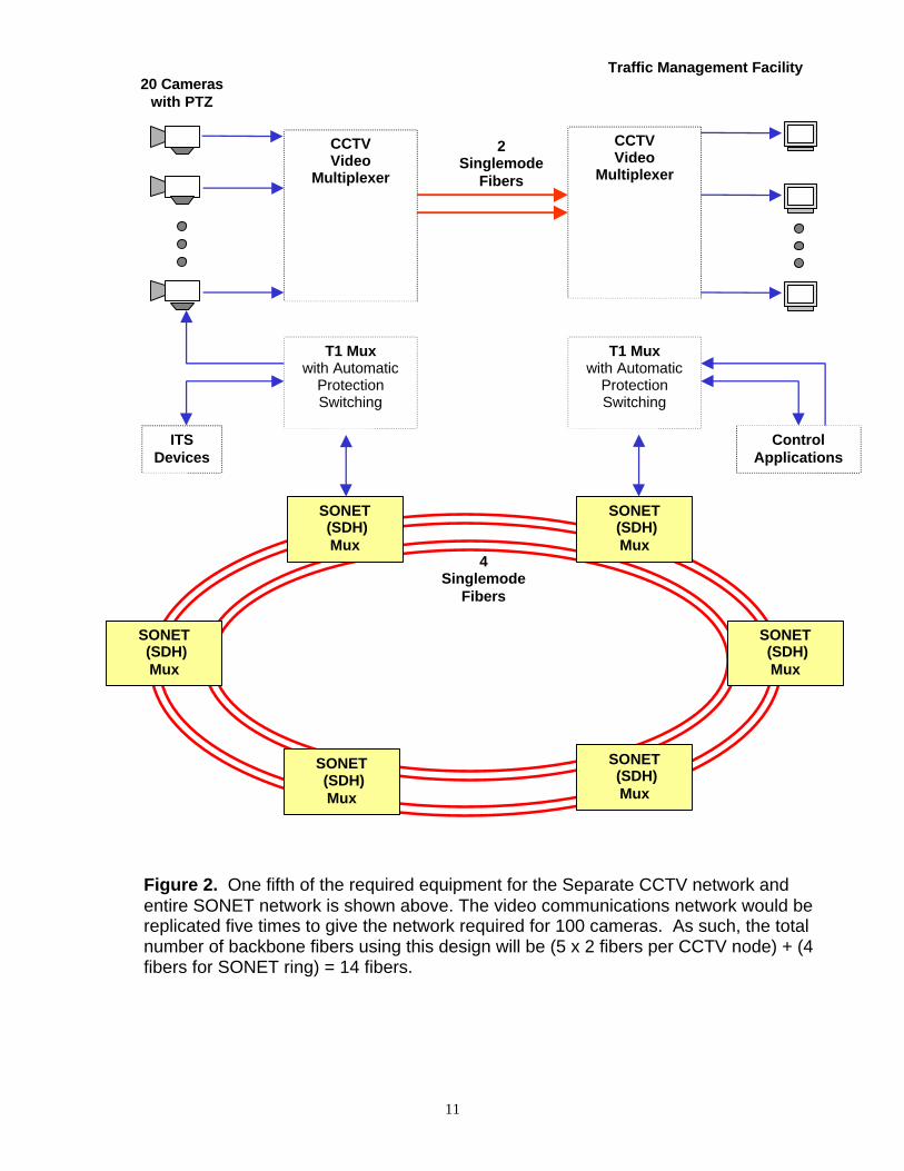
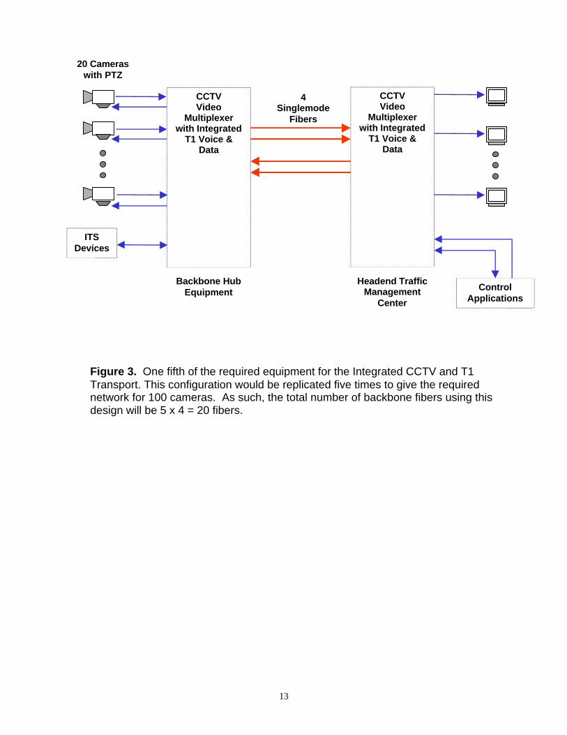
CCTV with T1 TransportA similar network topology to the separate video and data network already discussed is one inwhich the CCTV video signals are combined with an embedded high speed digital link for voiceand data as shown in Figure 3. The key difference in this case is that the fiber optic transmissionlink previously used for video only is now used for the integrated transmission of video, voiceand data. This requires that the communications equipment be capable of bi-directional datatransmission for the T1 voice and data signal. Transmission redundancy for fault-toleranceshould also be built into the video multiplexing equipment, hence eliminating the previous needfor Automatic Protection Switching equipment. Although this network topology is very similarto the separate video and data network, it has the advantage of requiring only 20 optical fibers incontrast to the 30 for the separate CCTV and T1 networks.
13
20 Cameraswith PTZ
ITSDevices
CCTVVideo
Multiplexerwith Integrated
T1 Voice &Data
ControlApplications
4Singlemode
Fibers
Backbone HubEquipment
Headend TrafficManagement
Center
Figure 3. One fifth of the required equipment for the Integrated CCTV and T1Transport. This configuration would be replicated five times to give the requirednetwork for 100 cameras. As such, the total number of backbone fibers using thisdesign will be 5 x 4 = 20 fibers.
CCTVVideo
Multiplexerwith Integrated
T1 Voice &Data
14
Digital Video over SONETA completely digital solution is ultimately desirable due to the fact that the same “pipe” servesall three information formats (video, voice and data) interchangeably. Digital transport of allinformation on the network facilitates interoperability with the deployed networks of otheragencies. Additionally, the Public Switched Telephone Network (PSTN) can be used to relayinformation digitally between Traffic Control Centers or to disseminate video images to thepublic over the Internet (for example).
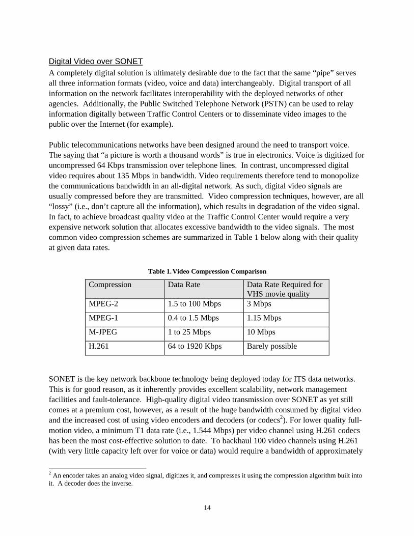
Public telecommunications networks have been designed around the need to transport voice.The saying that “a picture is worth a thousand words” is true in electronics. Voice is digitized foruncompressed 64 Kbps transmission over telephone lines. In contrast, uncompressed digitalvideo requires about 135 Mbps in bandwidth. Video requirements therefore tend to monopolizethe communications bandwidth in an all-digital network. As such, digital video signals areusually compressed before they are transmitted. Video compression techniques, however, are all“lossy” (i.e., don’t capture all the information), which results in degradation of the video signal.In fact, to achieve broadcast quality video at the Traffic Control Center would require a veryexpensive network solution that allocates excessive bandwidth to the video signals. The mostcommon video compression schemes are summarized in Table 1 below along with their qualityat given data rates.
Table 1.Video Compression Comparison
Compression Data Rate Data Rate Required forVHS movie quality
MPEG-2 1.5 to 100 Mbps 3 Mbps
MPEG-1 0.4 to 1.5 Mbps 1.15 Mbps
M-JPEG 1 to 25 Mbps 10 Mbps
H.261 64 to 1920 Kbps Barely possible
SONET is the key network backbone technology being deployed today for ITS data networks.This is for good reason, as it inherently provides excellent scalability, network managementfacilities and fault-tolerance. High-quality digital video transmission over SONET as yet stillcomes at a premium cost, however, as a result of the huge bandwidth consumed by digital videoand the increased cost of using video encoders and decoders (or codecs2). For lower quality full-motion video, a minimum T1 data rate (i.e., 1.544 Mbps) per video channel using H.261 codecshas been the most cost-effective solution to date. To backhaul 100 video channels using H.261(with very little capacity left over for voice or data) would require a bandwidth of approximately
2 An encoder takes an analog video signal, digitizes it, and compresses it using the compression algorithm built intoit. A decoder does the inverse.
15
155 Mbps, or a SONET OC-3 network. Adding voice and/or data to the network would push thebandwidth requirements to the next level of the SONET hierarchy, or OC-12 (at 622.08 Mbps).For Super VHS quality video, MPEG-2 at 6 Mbps per video channel is required. This isequivalent to dedicating four T1 channels per video signal. Hence for 100 video channels, aminimum capacity of 400 T1’s or 618 Mbps is required. This corresponds to a SONET OC-12data rate. Adding any significant amount of voice and/or data requirements would push thebandwidth requirements to the next level of the SONET hierarchy, or OC-48 (with a 2488.32Mbps capacity). As both OC-12 and OC-48 networks are relatively expensive to implement,OC-3 networks are usually implemented and a compromise on video quality is accepted.
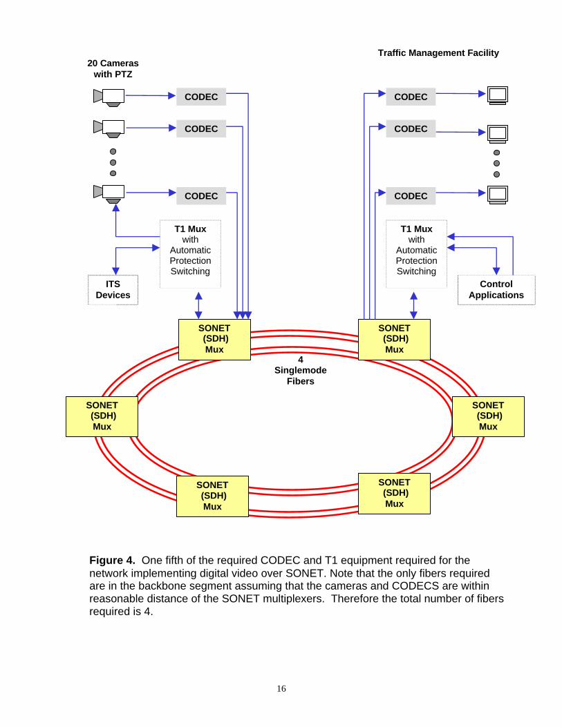
A SONET network as illustrated in Figure 4 provides the most efficient use of existing fiber.Given SONET’s extraordinary capacity, network growth can typically be accomplished onexisting optical fibers with the odd exception being for very large networks. Higher speedSONET equipment (e.g., OC-48) that is interoperable with the existing equipment can bedeployed at a later stage should the current equipment capacity ever be exceeded (provided thevendor’s equipment allows such an upgrade).
16
20 Cameraswith PTZ
ITSDevices
T1 Muxwith
AutomaticProtectionSwitching
SONET (SDH)Mux
ControlApplications
SONET (SDH)Mux
SONET (SDH)Mux
SONET (SDH)Mux
SONET (SDH)Mux
SONET (SDH)Mux
Traffic Management Facility
Figure 4. One fifth of the required CODEC and T1 equipment required for thenetwork implementing digital video over SONET. Note that the only fibers requiredare in the backbone segment assuming that the cameras and CODECS are withinreasonable distance of the SONET multiplexers. Therefore the total number of fibersrequired is 4.
4Singlemode
Fibers
CODEC
CODEC
CODEC
T1 Muxwith
AutomaticProtectionSwitching
CODEC
CODEC
CODEC

17
The Hybrid CCTV/SONET NetworkAn integrated network design alternative which draws on the strengths of each of the previouslydiscussed architectures is represented by the hybrid solution of Figure 5. It employs each of thefollowing elements:
• A SONET data/voice backbone for high fault-tolerance, efficient optical fiber usage,interoperability with other SIF-compliant SONET-based deployments, and gracefulmigration to digital video as video compression technology becomes more cost-effective.The SONET equipment is used primarily for voice and data services.
• CCTV video communications equipment for high quality, full-motion, low-cost video.
• Optical integration of the CCTV Video and SONET signals through Wavelength DivisionMultiplexing (WDM) technology; this state-of-the-art technology allows the integration oftwo distinct optical signals (operating at different wavelengths) for transport over a singleoptical fiber.
The hybrid network offers the flexibility of having both low-cost, broadcast quality video circuitsand digitized video over SONET when required (note that Figure 5 assumes no digital video inorder to achieve the lowest cost solution). This solution prevents the SONET network frombecoming rapidly congested (which might otherwise happen owing to the large bandwidthrequirements of digital video). The SONET network can now be optimally used for ITS andother municipal data and voice requirements.

18
20 Cameraswith PTZ
ITSDevices
T1 Muxwith Automatic
ProtectionSwitching
CCTVVideo
Multiplexer
SONET (SDH)Mux
CCTVVideo
Multiplexer
T1 Muxwith
AutomaticProtectionSwitching
ControlApplications
SONET (SDH)Mux
SONET (SDH)Mux
SONET (SDH)Mux
SONET (SDH)Mux
SONET (SDH)Mux
Traffic Management Facility
2SinglemodeFibers (short
pigtails)
Figure 5. A partial representation of the Hybrid Network architecture (the CCTV andT1 multiplexing equipment would have to be replicated at each SONET node to givethe network required for 100 cameras). Since the CCTV multiplexing equipment isoptically integrated with the SONET signal, the total number of backbone fibersrequired equals the SONET ring backbone = 4 fibers.
4SinglemodeFibers in the
Backbone
WDMWDM
2SinglemodeFibers (short
pigtails)
19
NETWORK DESIGN COMPARISONS
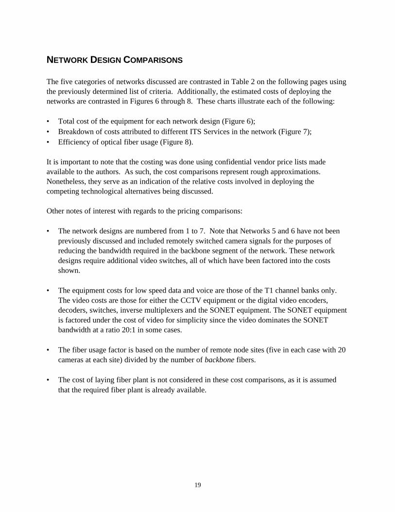
The five categories of networks discussed are contrasted in Table 2 on the following pages usingthe previously determined list of criteria. Additionally, the estimated costs of deploying thenetworks are contrasted in Figures 6 through 8. These charts illustrate each of the following:
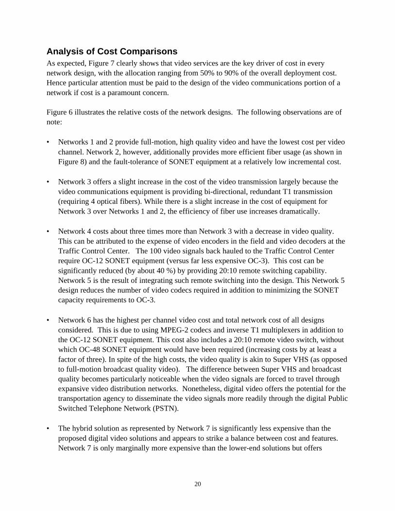
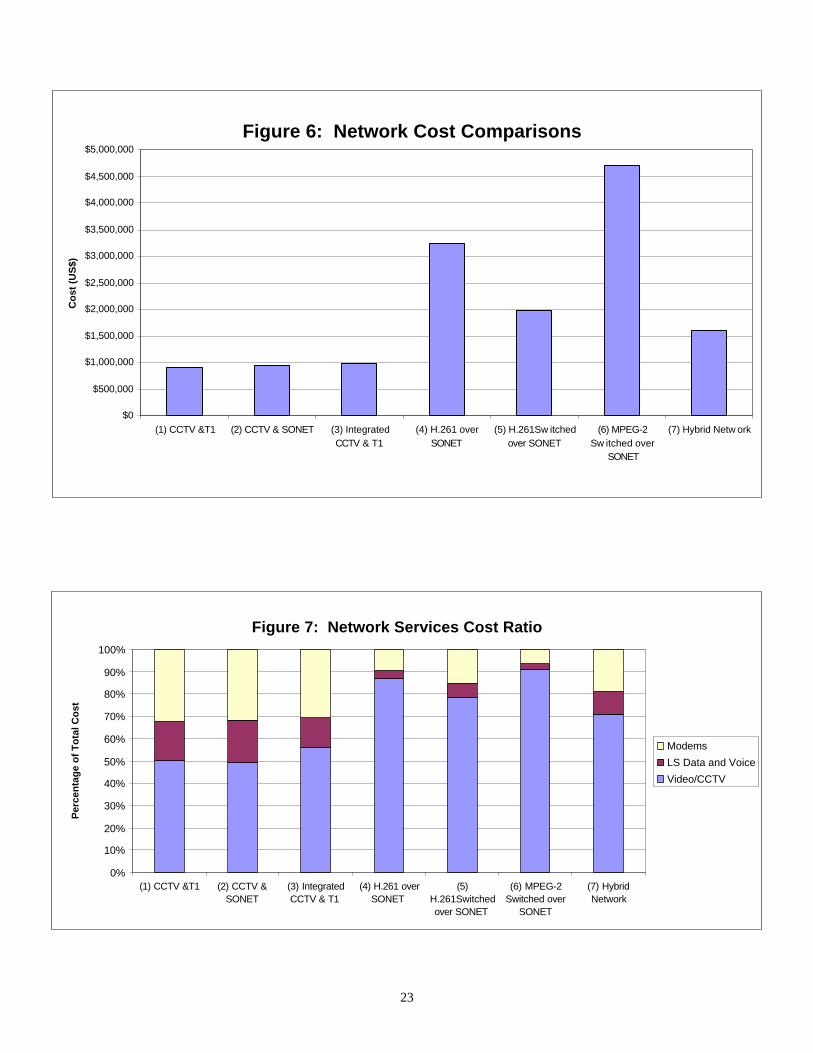
• Total cost of the equipment for each network design (Figure 6);• Breakdown of costs attributed to different ITS Services in the network (Figure 7);• Efficiency of optical fiber usage (Figure 8).
It is important to note that the costing was done using confidential vendor price lists madeavailable to the authors. As such, the cost comparisons represent rough approximations.Nonetheless, they serve as an indication of the relative costs involved in deploying thecompeting technological alternatives being discussed.
Other notes of interest with regards to the pricing comparisons:
• The network designs are numbered from 1 to 7. Note that Networks 5 and 6 have not beenpreviously discussed and included remotely switched camera signals for the purposes ofreducing the bandwidth required in the backbone segment of the network. These networkdesigns require additional video switches, all of which have been factored into the costsshown.
• The equipment costs for low speed data and voice are those of the T1 channel banks only.The video costs are those for either the CCTV equipment or the digital video encoders,decoders, switches, inverse multiplexers and the SONET equipment. The SONET equipmentis factored under the cost of video for simplicity since the video dominates the SONETbandwidth at a ratio 20:1 in some cases.
• The fiber usage factor is based on the number of remote node sites (five in each case with 20cameras at each site) divided by the number of backbone fibers.
• The cost of laying fiber plant is not considered in these cost comparisons, as it is assumedthat the required fiber plant is already available.
20
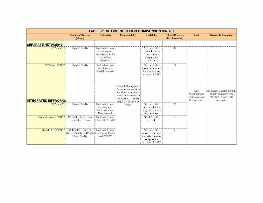
Analysis of Cost ComparisonsAs expected, Figure 7 clearly shows that video services are the key driver of cost in everynetwork design, with the allocation ranging from 50% to 90% of the overall deployment cost.Hence particular attention must be paid to the design of the video communications portion of anetwork if cost is a paramount concern.
Figure 6 illustrates the relative costs of the network designs. The following observations are ofnote:
• Networks 1 and 2 provide full-motion, high quality video and have the lowest cost per videochannel. Network 2, however, additionally provides more efficient fiber usage (as shown inFigure 8) and the fault-tolerance of SONET equipment at a relatively low incremental cost.
• Network 3 offers a slight increase in the cost of the video transmission largely because thevideo communications equipment is providing bi-directional, redundant T1 transmission(requiring 4 optical fibers). While there is a slight increase in the cost of equipment forNetwork 3 over Networks 1 and 2, the efficiency of fiber use increases dramatically.
• Network 4 costs about three times more than Network 3 with a decrease in video quality.This can be attributed to the expense of video encoders in the field and video decoders at theTraffic Control Center. The 100 video signals back hauled to the Traffic Control Centerrequire OC-12 SONET equipment (versus far less expensive OC-3). This cost can besignificantly reduced (by about 40 %) by providing 20:10 remote switching capability.Network 5 is the result of integrating such remote switching into the design. This Network 5design reduces the number of video codecs required in addition to minimizing the SONETcapacity requirements to OC-3.
• Network 6 has the highest per channel video cost and total network cost of all designsconsidered. This is due to using MPEG-2 codecs and inverse T1 multiplexers in addition tothe OC-12 SONET equipment. This cost also includes a 20:10 remote video switch, withoutwhich OC-48 SONET equipment would have been required (increasing costs by at least afactor of three). In spite of the high costs, the video quality is akin to Super VHS (as opposedto full-motion broadcast quality video). The difference between Super VHS and broadcastquality becomes particularly noticeable when the video signals are forced to travel throughexpansive video distribution networks. Nonetheless, digital video offers the potential for thetransportation agency to disseminate the video signals more readily through the digital PublicSwitched Telephone Network (PSTN).
• The hybrid solution as represented by Network 7 is significantly less expensive than theproposed digital video solutions and appears to strike a balance between cost and features.Network 7 is only marginally more expensive than the lower-end solutions but offers

21
SONET backbone, fiber usage efficiency, and the ability to gracefully migrate towards digitalvideo solutions as they become less expensive over time.
23
Figure 6: Network Cost Comparisons
$0
$500,000
$1,000,000
$1,500,000
$2,000,000
$2,500,000
$3,000,000
$3,500,000
$4,000,000
$4,500,000
$5,000,000
(1) CCTV &T1 (2) CCTV & SONET (3) IntegratedCCTV & T1
(4) H.261 overSONET
(5) H.261Sw itchedover SONET
(6) MPEG-2Sw itched over
SONET
(7) Hybrid Netw ork
Co
st (
US
$)
Figure 7: Network Services Cost Ratio
0%
10%
20%
30%
40%
50%
60%
70%
80%
90%
100%
(1) CCTV &T1 (2) CCTV &SONET
(3) IntegratedCCTV & T1
(4) H.261 overSONET
(5)H.261Switchedover SONET
(6) MPEG-2Switched over
SONET
(7) HybridNetwork
Per
cen
tag
e o
f T
ota
l Co
st
Modems
LS Data and Voice
Video/CCTV

24
Figure 8: Fiber Efficiency per Network
0.00
0.20
0.40
0.60
0.80
1.00
1.20
1.40
(1) CCTV &T1 (2) CCTV & SONET (3) Integrated CCTV &T1
(4) H.261 over SONET (5) H.261Sw itchedover SONET
(6) MPEG-2 Sw itchedover SONET
(7) Hybrid Netw ork
Fib
er E
ffic
ien
cy
25
CONCLUSION
Every fiber optic ITS communications network will have its own unique set of requirements. Assuch, the specific criteria to be addressed by the network design must be well understood beforedetermining the most appropriate network design.
The five network design architectures discussed each offer their own respective strengths andweaknesses, with the hybrid network approach (CCTV video multiplexers wavelength divisionmultiplexed with SONET equipment) ostensibly representing the highest value-added solution.The final design choice made by network design consultants and transportation agencies shouldbe based on the network design option that best addresses the criteria established for theparticular project in question. Following the network design assessment framework outlined inthis paper will assist in achieving this goal.