DESIGN BY MATERIAL: FROM MATERIAL TO FORM THROUGH …
10
Cite this article: Ostrosi, E., Bluntzer, J.-B., Baume, H., Stjepandić, J. (2021) ‘Design by Material: From Material to Form Through CAD Modelling’, in Proceedings of the International Conference on Engineering Design (ICED21), Gothenburg, Sweden, 16-20 August 2021. DOI:10.1017/pds.2021.96 ICED21 963 INTERNATIONAL CONFERENCE ON ENGINEERING DESIGN, ICED21 16-20 AUGUST 2021, GOTHENBURG, SWEDEN DESIGN BY MATERIAL: FROM MATERIAL TO FORM THROUGH CAD MODELLING Ostrosi, Egon (1); Bluntzer, Jean-Bernard (2); Baume, Hugues (2); Stjepandić, Josip (3) 1: Université de Bourgogne Franche-Comté, UTBM, Pôle Industrie 4.0, ERCOS/ELLIADD, France; 2: Université de Bourgogne Franche-Comté, UTBM, Pôle Transports et Mobilités, ERCOS/ELLIADD, France; 3: PROSTEP AG, Darmstadt, Germany ABSTRACT For Aristotelian scholars, matter is identified as the subject of change, while form is the boundary of matter. Design is a process of bringing about change. From a design perspective, material is what an entity is made from; form is what makes a thing what it is. Based on the principle, “form is the boundary of matter”, this paper proposes a Design by Material method, thereby addressing the knowledge gap of a systematic method for designing according to material. This method is predicated on the material specification as the first input in the design process. A formal model is built in which the material acts as a trigger and driver for the design process. The method is implemented by integrating computer-aided design (CAD) modelling and its design form. A design application is explained to demonstrate the relevance of the Design by Material method. Keywords: Design for X (DfX), Computer Aided Design (CAD), Product modelling / models, Form, Skeleton Contact: Bluntzer, Jean-Bernard Université de Technologie de Belfort-Montbéliard, France ELLIADD- ERCOS France [email protected]
Transcript of DESIGN BY MATERIAL: FROM MATERIAL TO FORM THROUGH …
Cite this article: Ostrosi, E., Bluntzer, J.-B., Baume, H., Stjepandić, J. (2021) ‘Design by Material: From Material to Form Through CAD Modelling’, in Proceedings of the International Conference on Engineering Design (ICED21), Gothenburg, Sweden, 16-20 August 2021. DOI:10.1017/pds.2021.96
ICED21 963
INTERNATIONAL CONFERENCE ON ENGINEERING DESIGN, ICED21 16-20 AUGUST 2021, GOTHENBURG, SWEDEN
ICED21 1
DESIGN BY MATERIAL: FROM MATERIAL TO FORM THROUGH CAD MODELLING Ostrosi, Egon (1); Bluntzer, Jean-Bernard (2); Baume, Hugues (2); Stjepandić, Josip (3) 1: Université de Bourgogne Franche-Comté, UTBM, Pôle Industrie 4.0, ERCOS/ELLIADD, France; 2: Université de Bourgogne Franche-Comté, UTBM, Pôle Transports et Mobilités, ERCOS/ELLIADD, France; 3: PROSTEP AG, Darmstadt, Germany
ABSTRACT For Aristotelian scholars, matter is identified as the subject of change, while form is the boundary of matter. Design is a process of bringing about change. From a design perspective, material is what an entity is made from; form is what makes a thing what it is. Based on the principle, “form is the boundary of matter”, this paper proposes a Design by Material method, thereby addressing the knowledge gap of a systematic method for designing according to material. This method is predicated on the material specification as the first input in the design process. A formal model is built in which the material acts as a trigger and driver for the design process. The method is implemented by integrating computer-aided design (CAD) modelling and its design form. A design application is explained to demonstrate the relevance of the Design by Material method. Keywords: Design for X (DfX), Computer Aided Design (CAD), Product modelling / models, Form, Skeleton Contact: Bluntzer, Jean-Bernard Université de Technologie de Belfort-Montbéliard, France ELLIADD- ERCOS France [email protected]
964 ICED21
1 INTRODUCTION
Though form is a mainstay of product design, it is still an under-researched area of the design
literature (Kahane, 2015). The traditional design method, based on the principle, “form follows
function,” is the core of established design approaches (Pugh, 1991; Ullman, 1992; Ulrich, 1995;
Eppinger and Ulrich, 2015; Pahl and Beitz, 2013). A deficiency of this approach is that it does not
encompass the other factors which affect form, other than function.
The notion of form was introduced by the Greek philosophers. Matter and form, which together make
up every ordinary object, are considered contrasting notions in Aristotelian philosophy. They are
introduced as distinct causes for the explication of changeable reality. Aristotle identified matter as the
subject of change, while form is the boundary of matter which has undergone a change. By adapting
Aristotelian theories of form to a contemporary design context, this paper offers a new design
paradigm of “Design by Material.”
The question of changing is universal and thus results in generic solutions in different scientific
disciplines. Matter is the source of physical things, and this is an intrinsic principle of change. As
such, matter is a potentiality, potency or capacity. In physics, Nobel Prize winner Heisenberg found
that quantum physics restored the Aristotelian notion of the potency of matter (Heisenberg, 1958). The
extended uses of matter and form in logic and in mathematics are analogous to their applications in the
physical order. In topology, Thom, who received the Fields Medal in 1958, defined form as the
boundary of matter (Thom, 1991). As such, form is the actuality, the boundary of potentiality;
shapeless matter is enveloped by form. Mathematics considers matter and form through the nature of
the continuum, meaning that the underlying substrate of both matter and form is continuous.
From another point of view, matter is that from which a thing is made, and form is what makes a thing
what it is. In embryology, Waddington studied the processes of morphogenesis that transform an
apparently uniform ball of cells into a layered structure of differentiated tissues (Waddington, 1940).
The surprising discovery was made that material substance acts as a trigger for some complex
sequences of events. This provides evidence for the understanding that all natural forms are inherently
also material beings. As a consequence, a specification of matter is contained in an entity’s form
(Peramatzis, 2011).
Industrial products also have a material substance and form. According to Aristotelian thinking, if the
form of an industrial product is the result of a material substance, then it follows that its material
substance has an appetite to possess the form. For any material substance, new form is brought about
from the material by design, often by emergence. Form, which is the act, is the boundary of the
material substance, which is its potency or capacity. Following this logic, Design by Material thus
becomes a new paradigm of design.
Bak-Anderson describes a material-driven design process, in which the material is presented from the
outset and can be seen as the driver of the process (Bak-Andersen, 2018). This material-driven design
process breaks down the knowledge barrier between the designer and the product and reveals the
potential of enabling design for sustainability. The quandary in the relationship between form and
matter in established contemporary design processes is analysed and specifies the cross-disciplinary
field in which material-driven design for sustainability is placed. A further method, Material Driven
Design (MDD), was developed by Karana et al. to facilitate designing for material experiences
(Karana et al., 2015).
As a result of development toward ‘smart’ materials (Sigmund and Torquato, 1999; Addington and
Schodek, 2005; Liu et al., 2013; Bengisu and Ferrara, 2018), materials now enable an expanding range
of aesthetic expressions and user experiences. These materials are fundamentally temporal in their
capacity to assume multiple, discrete states of expression that can be repeatedly and minutely
controlled. Bergström et al. introduce and discuss the concept of becoming materials – as well as the
implications for practice – through a series of examples from our own practice-led research within art,
design, and architecture (Bergström et al., 2010).
Although the material and form become actively involved in the creative challenge for materials to
possess the form, there is not a systematic method to date on how to Design by Material. Based on the
principle, “form is the boundary of matter,” a Design by Materials method is proposed in this paper. It
argues that a material, with its inherent potentiality, triggers and drives the form of the product in a
collaborative way, integrating computer-aided design (CAD) modelling and the designer.
ICED21 965
The remainder of this paper is structured as follows: in Section 2, a formal model is proposed. Section
3 describes an application of the formal model and Section 4 summarizes the conclusions and future
research possibilities.
2 FORMAL MODEL - THE ARCHITECTURE OF THE PROPOSED METHOD
Working with “skeletons,” which are simplified models, brings flexibility in the design process
(Biahmou et al., 2016). Depending on the level of conceptualization, a skeleton is a simplified shape
which is driven by functional requirements (FR) and embeds the working principles of the design
(Suh, 2001). The main objective of the skeleton is to validate the major specifications in the early
phases of the CAD process, without spending time on defining a detailed CAD model which will be
refined afterwards (Bley and Bossmann, 2006). A ‘skeleton’ is a basic concept in CAD modelling of
machines and mechanisms (Held et al., 2016; Ju et al., 2007). A CAD skeleton contains the structure
and the form of the future product (Bluntzer et al., 2016) (Ostrosi et al., 2020).
Many studies have already been carried out using skeleton-based modelling (Cornea et al., 2005,
2007; Levet and Granier, 2007; Li and Lachmayer, 2019; Schubert et al., 2011; Wade and Parent,
2002; Ziegler and Wartzack, 2013). Different types of skeletons and their roles in modelling have been
introduced: part skeleton, assembly skeleton and motion skeleton (Bluntzer et al., 2016).
A material skeleton solution, therefore, represents the architecture of a product by defining the
relationships between its simplified components to satisfy the performances of the material. Therefore,
the material will drive the product’s form. This simplified model is enriched gradually to satisfy the
whole set of functional and material requirements and the constraints imposed on the product.
A skeleton should formally contain the following information: (i) engineering requirements - design
loads, performance requirements, (ii) materials, and (iii) form. On the other hand, the form is defined
formally by (i) interfaces, which relate to the immediate proximity of importing and exporting design
loads; (ii) architecture, which defines the simplified form to channel the loads; (iii) an envelope which
defines where the form of the part can be without interfering with others.
To model the material skeleton and then the form, the functional requirements are split into two types:
(a) material requirements and (b) form requirements. This allows managing inputs for both skeleton
and form.
The specification of materials for a design is a key step in the design process because form (act) is the
boundary of the material substance (the potency or capacity). The mapping from the functional domain
to the physical domain is represented in Equation 1. In Equation 1, the vector on the right of the
equation shows what the functional requirements are in the functional domain. The vector on the left
shows how the functional requirements are satisfied by the physical solutions in the physical domain.
Finally, the matrix 𝐴[𝑎𝑖𝑗] shows the relationship between functional requirements and physical
solutions. An element 𝑎𝑖𝑗 of the design matrix 𝐴 shows the logical relationship between the elements
of the functional requirement vector and the elements of the physical solution vector. Thus, Equation 1
shows that the “Material Specification” and the “CAD Form” of the product are related to the material
requirements (“Specify Material Requirements"). The CAD Architecture, which defines the
relationships among the structural elements of the product, is defined by a “Material Skeleton.” It is
expressed by the functional requirement, “Hold the Body of the Product.” The “CAD Form” should
satisfy the functional requirement, “Support and Channel loads.”
[Material Specification
Material Skeleton
CAD Form
] = [𝑎11
𝑎21 𝑎22
𝑎31 𝑎32 𝑎33
] [
Specify Material Requirements
Hold the Body of the Product
Support and Channel Loads
] (1)
Knowing that a “Material Skeleton” should “Import/Export loads,” “Channel loads” and “Interact”
with the surroundings, the managed dependency between these functional requirements is shown by
Equation 2. An element 𝑐𝑖𝑗 of the matrix 𝐶[𝑐𝑖𝑗] shows the logical relationship between the
decomposed functional requirement “Hold the Body of the Product” and the decomposed “Material
Skeleton” physical solution.
[CAD Interface
CAD Architecture
CAD Envelope ] = [
𝑐11
𝑐21 𝑐22
𝑐31 𝑐32 𝑐33
] [Import/Export Loads
Channel Loads
Interact
] (2)
966 ICED21
Integrating Equation 2 into Equation 1 yields the following:
[ Material Selection
CAD Interface
CAD Architecture
CAD Envelope
CAD Form ]
=
[ 𝑎11
𝑎21 𝑎22
𝑎31 𝑎32 𝑎33
𝑎41 𝑎42 𝑎43 𝑎44
𝑎51 𝑎52 𝑎53 𝑎54 𝑎55]
[ Specify Material Requirements
Import/Export Loads
Channel Loads
Interact
Support and Channel Loads ]
(3)
The matrix 𝐴[𝑎𝑖𝑗] in Equation 3 shows and defines an order relation in the management of CAD
modelling for the Design by Materials method. It demonstrates that design modelling follows the
Aristotelian principle: specification of matter is contained in an entity’s form. The material skeleton is
built based on the specification of materials. The formal model’s content defines the design method
and establishes its basic architecture.
3 APPLICATION
A company intends to develop new product families of chairs to target different sections of the
consumer market. The company would like to find out what aspects of the product family involve
introducing different materials. When the material is changed, the design and CAD model are not well
suited to identify the product family. Adapting the old models to different materials does not provide
satisfactory results.
Applying Equation 1 to the design of chairs results in the following:
[Material Specification
Material Skeleton
CAD Form
] = [𝑎11
𝑎21 𝑎22
𝑎31 𝑎32 𝑎33
] [
Specify Material Requirements of Chair
Hold the Body of Chair
Support and Channel Loads of Chair
] (4)
3.1 Material Specification
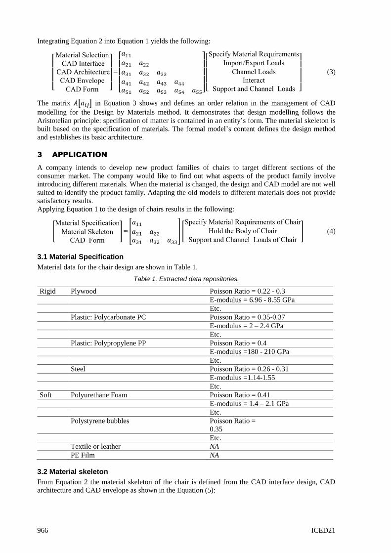
Material data for the chair design are shown in Table 1.
Table 1. Extracted data repositories.
Rigid Plywood Poisson Ratio = 0.22 - 0.3
E-modulus = 6.96 - 8.55 GPa
Etc.
Plastic: Polycarbonate PC Poisson Ratio = 0.35-0.37
E-modulus = 2 – 2.4 GPa
Etc.
Plastic: Polypropylene PP Poisson Ratio = 0.4
E-modulus =180 - 210 GPa
Etc.
Steel Poisson Ratio = 0.26 - 0.31
E-modulus =1.14-1.55
Etc.
Soft Polyurethane Foam Poisson Ratio = 0.41
E-modulus = 1.4 – 2.1 GPa
Etc.
Polystyrene bubbles Poisson Ratio =
0.35
Etc.
Textile or leather NA
PE Film NA
3.2 Material skeleton
From Equation 2 the material skeleton of the chair is defined from the CAD interface design, CAD
architecture and CAD envelope as shown in the Equation (5):
ICED21 967
[CAD Interface
CAD Architecture
CAD Envelope ] = [
𝑐11
𝑐21 𝑐22
𝑐31 𝑐32 𝑐33
] [Import/Export Loads of Chair
Channel Loads of Chair
Interact with Users and Ground
] (5)
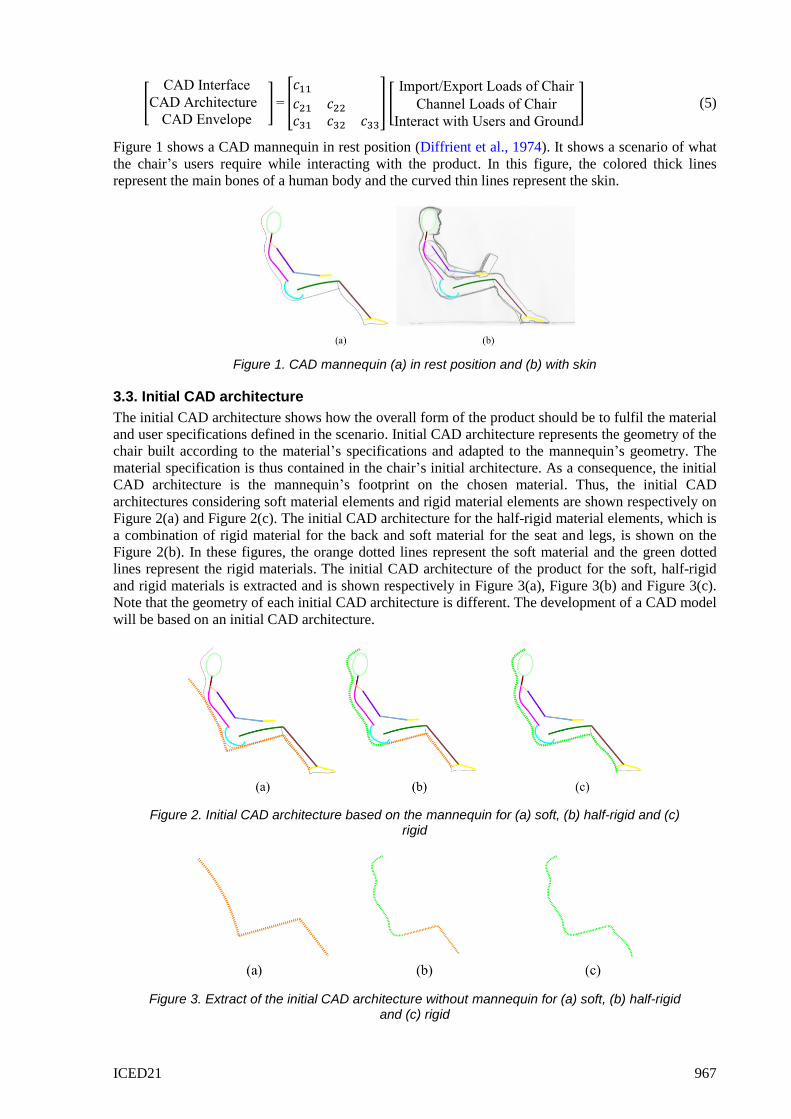
Figure 1 shows a CAD mannequin in rest position (Diffrient et al., 1974). It shows a scenario of what
the chair’s users require while interacting with the product. In this figure, the colored thick lines
represent the main bones of a human body and the curved thin lines represent the skin.
Figure 1. CAD mannequin (a) in rest position and (b) with skin
3.3. Initial CAD architecture
The initial CAD architecture shows how the overall form of the product should be to fulfil the material
and user specifications defined in the scenario. Initial CAD architecture represents the geometry of the
chair built according to the material’s specifications and adapted to the mannequin’s geometry. The
material specification is thus contained in the chair’s initial architecture. As a consequence, the initial
CAD architecture is the mannequin’s footprint on the chosen material. Thus, the initial CAD
architectures considering soft material elements and rigid material elements are shown respectively on
Figure 2(a) and Figure 2(c). The initial CAD architecture for the half-rigid material elements, which is
a combination of rigid material for the back and soft material for the seat and legs, is shown on the
Figure 2(b). In these figures, the orange dotted lines represent the soft material and the green dotted
lines represent the rigid materials. The initial CAD architecture of the product for the soft, half-rigid
and rigid materials is extracted and is shown respectively in Figure 3(a), Figure 3(b) and Figure 3(c).
Note that the geometry of each initial CAD architecture is different. The development of a CAD model
will be based on an initial CAD architecture.
Figure 2. Initial CAD architecture based on the mannequin for (a) soft, (b) half-rigid and (c) rigid
Figure 3. Extract of the initial CAD architecture without mannequin for (a) soft, (b) half-rigid and (c) rigid
968 ICED21
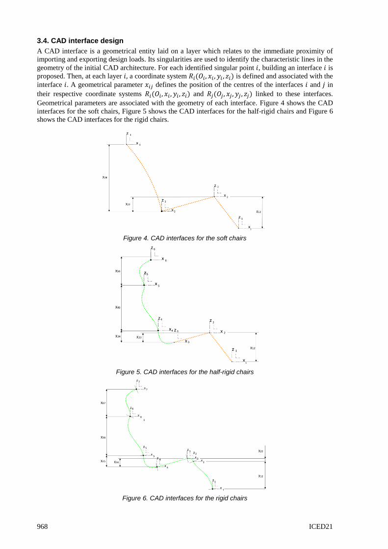
3.4. CAD interface design
A CAD interface is a geometrical entity laid on a layer which relates to the immediate proximity of
importing and exporting design loads. Its singularities are used to identify the characteristic lines in the
geometry of the initial CAD architecture. For each identified singular point 𝑖, building an interface 𝑖 is
proposed. Then, at each layer 𝑖, a coordinate system 𝑅𝑖(𝑂𝑖, 𝑥𝑖 , 𝑦𝑖 , 𝑧𝑖) is defined and associated with the
interface 𝑖. A geometrical parameter 𝑥𝑖𝑗 defines the position of the centres of the interfaces 𝑖 and 𝑗 in
their respective coordinate systems 𝑅𝑖(𝑂𝑖, 𝑥𝑖 , 𝑦𝑖 , 𝑧𝑖) and 𝑅𝑗(𝑂𝑗, 𝑥𝑗, 𝑦𝑗 , 𝑧𝑗) linked to these interfaces.
Geometrical parameters are associated with the geometry of each interface. Figure 4 shows the CAD
interfaces for the soft chairs, Figure 5 shows the CAD interfaces for the half-rigid chairs and Figure 6
shows the CAD interfaces for the rigid chairs.
Figure 4. CAD interfaces for the soft chairs
Figure 5. CAD interfaces for the half-rigid chairs
Figure 6. CAD interfaces for the rigid chairs
ICED21 969
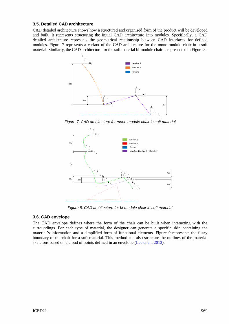
3.5. Detailed CAD architecture
CAD detailed architecture shows how a structured and organised form of the product will be developed
and built. It represents structuring the initial CAD architecture into modules. Specifically, a CAD
detailed architecture represents the geometrical relationship between CAD interfaces for defined
modules. Figure 7 represents a variant of the CAD architecture for the mono-module chair in a soft
material. Similarly, the CAD architecture for the soft material bi-module chair is represented in Figure 8.
Figure 7. CAD architecture for mono module chair in soft material
Figure 8. CAD architecture for bi-module chair in soft material
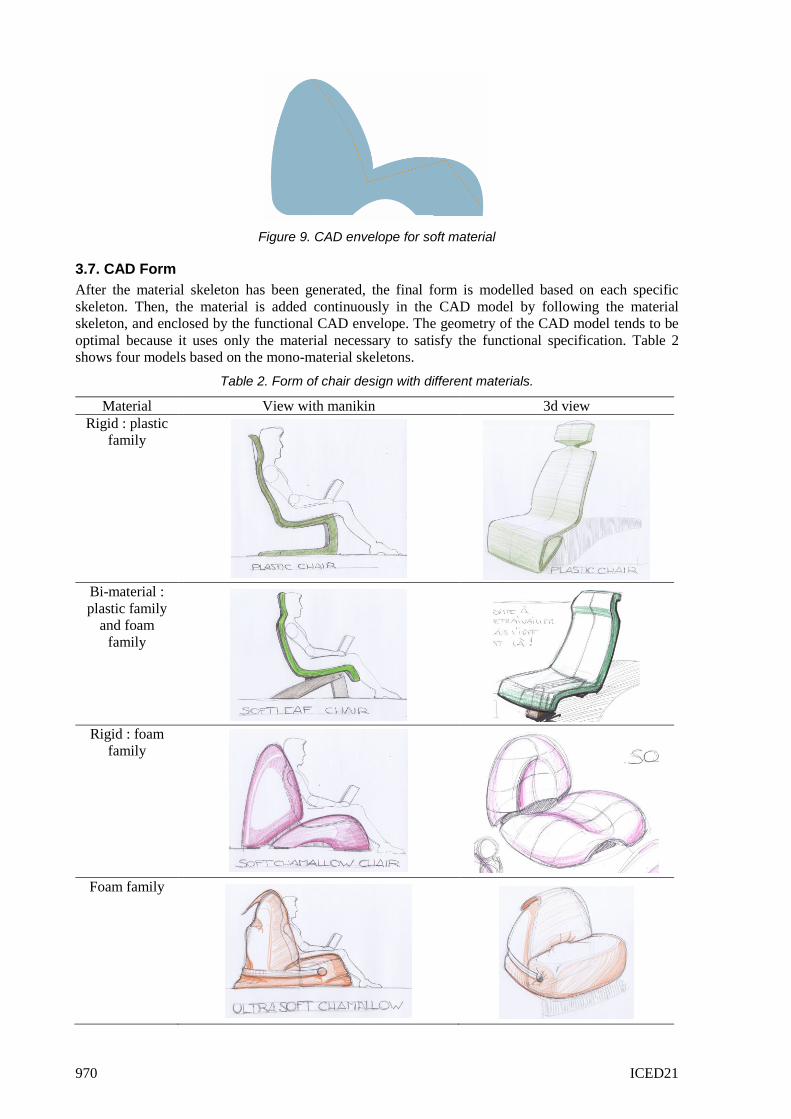
3.6. CAD envelope
The CAD envelope defines where the form of the chair can be built when interacting with the
surroundings. For each type of material, the designer can generate a specific skin containing the
material’s information and a simplified form of functional elements. Figure 9 represents the fuzzy
boundary of the chair for a soft material. This method can also structure the outlines of the material
skeletons based on a cloud of points defined in an envelope (Lee et al., 2013).
970 ICED21
Figure 9. CAD envelope for soft material
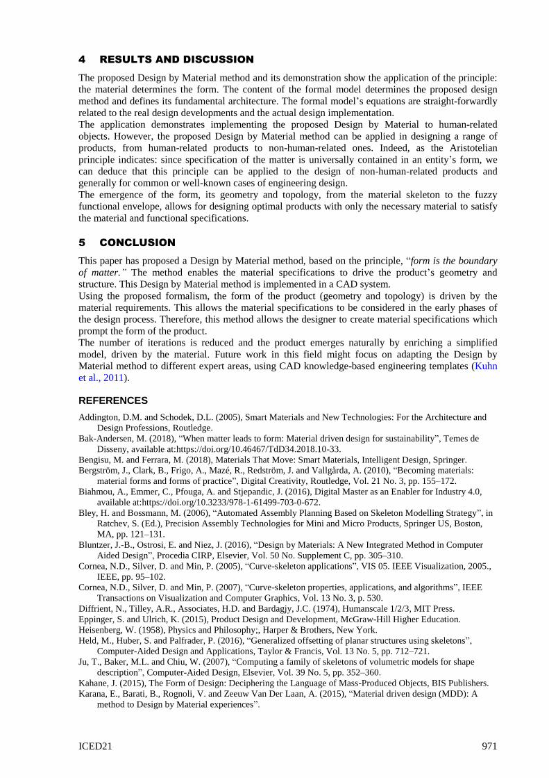
3.7. CAD Form
After the material skeleton has been generated, the final form is modelled based on each specific
skeleton. Then, the material is added continuously in the CAD model by following the material
skeleton, and enclosed by the functional CAD envelope. The geometry of the CAD model tends to be
optimal because it uses only the material necessary to satisfy the functional specification. Table 2
shows four models based on the mono-material skeletons.
Table 2. Form of chair design with different materials.
Material View with manikin 3d view
Rigid : plastic
family
Bi-material :
plastic family
and foam
family
Rigid : foam
family
Foam family
ICED21 971
4 RESULTS AND DISCUSSION
The proposed Design by Material method and its demonstration show the application of the principle:
the material determines the form. The content of the formal model determines the proposed design
method and defines its fundamental architecture. The formal model’s equations are straight-forwardly
related to the real design developments and the actual design implementation.
The application demonstrates implementing the proposed Design by Material to human-related
objects. However, the proposed Design by Material method can be applied in designing a range of
products, from human-related products to non-human-related ones. Indeed, as the Aristotelian
principle indicates: since specification of the matter is universally contained in an entity’s form, we
can deduce that this principle can be applied to the design of non-human-related products and
generally for common or well-known cases of engineering design.
The emergence of the form, its geometry and topology, from the material skeleton to the fuzzy
functional envelope, allows for designing optimal products with only the necessary material to satisfy
the material and functional specifications.
5 CONCLUSION
This paper has proposed a Design by Material method, based on the principle, “form is the boundary
of matter.” The method enables the material specifications to drive the product’s geometry and
structure. This Design by Material method is implemented in a CAD system.
Using the proposed formalism, the form of the product (geometry and topology) is driven by the
material requirements. This allows the material specifications to be considered in the early phases of
the design process. Therefore, this method allows the designer to create material specifications which
prompt the form of the product.
The number of iterations is reduced and the product emerges naturally by enriching a simplified
model, driven by the material. Future work in this field might focus on adapting the Design by
Material method to different expert areas, using CAD knowledge-based engineering templates (Kuhn
et al., 2011).
REFERENCES
Addington, D.M. and Schodek, D.L. (2005), Smart Materials and New Technologies: For the Architecture and
Design Professions, Routledge.
Bak-Andersen, M. (2018), “When matter leads to form: Material driven design for sustainability”, Temes de
Disseny, available at:https://doi.org/10.46467/TdD34.2018.10-33.
Bengisu, M. and Ferrara, M. (2018), Materials That Move: Smart Materials, Intelligent Design, Springer.
Bergström, J., Clark, B., Frigo, A., Mazé, R., Redström, J. and Vallgårda, A. (2010), “Becoming materials:
material forms and forms of practice”, Digital Creativity, Routledge, Vol. 21 No. 3, pp. 155–172.
Biahmou, A., Emmer, C., Pfouga, A. and Stjepandic, J. (2016), Digital Master as an Enabler for Industry 4.0,
available at:https://doi.org/10.3233/978-1-61499-703-0-672.
Bley, H. and Bossmann, M. (2006), “Automated Assembly Planning Based on Skeleton Modelling Strategy”, in
Ratchev, S. (Ed.), Precision Assembly Technologies for Mini and Micro Products, Springer US, Boston,
MA, pp. 121–131.
Bluntzer, J.-B., Ostrosi, E. and Niez, J. (2016), “Design by Materials: A New Integrated Method in Computer
Aided Design”, Procedia CIRP, Elsevier, Vol. 50 No. Supplement C, pp. 305–310.
Cornea, N.D., Silver, D. and Min, P. (2005), “Curve-skeleton applications”, VIS 05. IEEE Visualization, 2005.,
IEEE, pp. 95–102.
Cornea, N.D., Silver, D. and Min, P. (2007), “Curve-skeleton properties, applications, and algorithms”, IEEE
Transactions on Visualization and Computer Graphics, Vol. 13 No. 3, p. 530.
Diffrient, N., Tilley, A.R., Associates, H.D. and Bardagjy, J.C. (1974), Humanscale 1/2/3, MIT Press.
Eppinger, S. and Ulrich, K. (2015), Product Design and Development, McGraw-Hill Higher Education.
Heisenberg, W. (1958), Physics and Philosophy;, Harper & Brothers, New York.
Held, M., Huber, S. and Palfrader, P. (2016), “Generalized offsetting of planar structures using skeletons”,
Computer-Aided Design and Applications, Taylor & Francis, Vol. 13 No. 5, pp. 712–721.
Ju, T., Baker, M.L. and Chiu, W. (2007), “Computing a family of skeletons of volumetric models for shape
description”, Computer-Aided Design, Elsevier, Vol. 39 No. 5, pp. 352–360.
Kahane, J. (2015), The Form of Design: Deciphering the Language of Mass-Produced Objects, BIS Publishers.
Karana, E., Barati, B., Rognoli, V. and Zeeuw Van Der Laan, A. (2015), “Material driven design (MDD): A
method to Design by Material experiences”.
972 ICED21
Kuhn, O., Liese, H. and Stjepandic, J. (2011), “Methodology for knowledge-based engineering template update”,
Building Innovation Pipelines through Computer-Aided Innovation, Springer, pp. 178–191.
Lee, J., Son, H., Kim, C. and Kim, C. (2013), “Skeleton-based 3D reconstruction of as-built pipelines from laser-
scan data”, Automation in Construction, Elsevier, Vol. 35, pp. 199–207.
Levet, F. and Granier, X. (2007), “Improved skeleton extraction and surface generation for sketch-based
modeling”, Proceedings of Graphics Interface 2007, Association for Computing Machinery, New York,
NY, USA, pp. 27–33.
Li, H. and Lachmayer, R. (2019), “Automated exploration of design solution space applying the Generative
Design Method”, DS 94: Proceedings of the Design Society: 22nd International Conference on Engineering
Design (ICED19), presented at the 22nd International Conference on Engineering Design (ICED19),
available at:https://doi.org/10.1017/dsi.2019.114.
Liu, K., Tian, Y. and Jiang, L. (2013), “Bio-inspired superoleophobic and smart materials: design, fabrication,
and application”, Progress in Materials Science, Elsevier, Vol. 58 No. 4, pp. 503–564.
Ostrosi, E., Bluntzer, J.-B. and Stjepandic, J. (2020), “A CAD Material Skeleton-Based Method for Sustainable
Design”, available at:https://doi.org/10.3233/ATDE200133.
Pahl, G. and Beitz, W. (2013), Engineering Design: A Systematic Method, Springer Science & Business Media.
Peramatzis, M. (2011), Priority in Aristotle’s Metaphysics, Oxford University Press, Oxford, New York.
Pugh, S. (1991), Total Design: Integrated Methods for Successful Product Engineering, Addison-Wesley.
Schubert, S., Feldhusen, J. and Nagarajah, A. (2011), “An method for more efficient variant design process”, DS
68-4: Proceedings of the 18th International Conference on Engineering Design (ICED 11), Impacting
Society through Engineering Design, Vol. 4: Product and Systems Design, Lyngby/Copenhagen, Denmark,
15.-19.08.2011.
Sigmund, O. and Torquato, S. (1999), “Design of smart composite materials using topology optimization”,
Smart Materials and Structures, IOP Publishing, Vol. 8 No. 3, p. 365.
Suh, N.P. (2001), Axiomatic Design: Advances and Applications, Oxford University Press, USA.
Thom, R. (1991), “Matière, forme et catastrophes”, Penser Avec Aristote, M. A. Sinaceur., Erès, Toulouse,
pp. 367–398.
Ullman, D.G. (1992), The Mechanical Design Process, Vol. 2, McGraw-Hill New York.
Ulrich, K. (1995), “The role of product architecture in the manufacturing firm”, Research Policy, Elsevier, Vol.
24 No. 3, pp. 419–440.
Waddington, C.H. (1940), Organisers and Genes by C. H. Waddington, The University Press.
Wade, L. and Parent, R.E. (2002), “Automated generation of control skeletons for use in animation”, The Visual
Computer, Vol. 18 No. 2, pp. 97–110.
Ziegler, P. and Wartzack, S. (2013), “Concept for tolerance design in early design stages based on skeleton
models”, DS 75-5: Proceedings of the 19th International Conference on Engineering Design (ICED13)
Design For Harmonies, Vol. 5: Design for X, Design to X, Seoul, Korea 19-22.08.2013.