DESIGN BRIEF MIX-USE DEVELOPMENT ICON 505 PRESTON …
43
CLARIDGE HOMES (PRESTON) INC. DESIGN BRIEF MIX-USE DEVELOPMENT ICON 505 PRESTON STREET OTTAWA, ONTARIO PROJECT: 31637-5.2.2 MARCH 2014 MAY 2013 MAY 2012
Transcript of DESIGN BRIEF MIX-USE DEVELOPMENT ICON 505 PRESTON …

CLARIDGE HOMES (PRESTON) INC.
DESIGN BRIEF MIX-USE DEVELOPMENT ICON 505 PRESTON STREET OTTAWA, ONTARIO
PROJECT: 31637-5.2.2 MARCH 2014 MAY 2013 MAY 2012

I B I G R O U P – P R O J E C T : 3 1 6 3 7 - 5 . 2 . 2
i
TABLE OF CONTENTS
1. INTRODUCTION ...................................................................................................................... 1
1.1 Development Servicing Study Checklist ............................................................................................. 1
1.2 Purpose .................................................................................................................................................. 1
1.3 Subject Site ............................................................................................................................................ 1
1.4 Pre-Consultation ................................................................................................................................... 1
1.5 Geotechnical Investigation ................................................................................................................... 2
2. WATER SUPPLY ..................................................................................................................... 3
2.1 Existing Conditions ............................................................................................................................... 3
2.2 Design Criteria ....................................................................................................................................... 3
2.3 Hydraulic Analysis ................................................................................................................................ 3
2.4 Proposed Water Plan ............................................................................................................................ 4
3. WASTEWATER DISPOSAL .................................................................................................... 5
3.1 Existing Conditions ............................................................................................................................... 5
3.2 Sewer Capacity Analysis ...................................................................................................................... 5
3.3 Proposed Wastewater Plan .................................................................................................................. 5
4. STORMWATER MANAGEMENT ............................................................................................ 6
4.1 Existing Conditions ............................................................................................................................... 6
4.2 Proposed Stormwater Outlet Plan ....................................................................................................... 6
4.3 Design Criteria ....................................................................................................................................... 6
4.3 .1 Maximum Al lowable Release Rate . . . . . . . . . . . . . . . . . . . . . . . . . . . . . . . . . . . . . . . . . . . . . . . . . . . . . . . . . . . . . . . . 6
4.3 .2 Uncontro l led Post -Development Condi t ions . . . . . . . . . . . . . . . . . . . . . . . . . . . . . . . . . . . . . . . . . . . . . . . . . 6
4.4 Water Quantity ....................................................................................................................................... 7
4.4 .1 Area S1 – Uncontro l led Landscaped Sidewalk Areas . . . . . . . . . . . . . . . . . . . . . . . . . . . . . . . . . . . . . 7
4.4 .2 Area R1 –Mechanical Roof . . . . . . . . . . . . . . . . . . . . . . . . . . . . . . . . . . . . . . . . . . . . . . . . . . . . . . . . . . . . . . . . . . . . . . . . . . 7
4.4 .3 Area R2 – Penthouse/Mechanical Roof . . . . . . . . . . . . . . . . . . . . . . . . . . . . . . . . . . . . . . . . . . . . . . . . . . . . . . . . . 7
4.4 .4 Area T1 – Remain ing Roof Top/TERRACE Areas . . . . . . . . . . . . . . . . . . . . . . . . . . . . . . . . . . . . . . . . . . . . 8
4.5 Cistern Storage ...................................................................................................................................... 8
4.6 Stormwater Management Summary .................................................................................................... 8
5. STORMWATER SITE MANAGEMENT ................................................................................... 9
6. APPROVALS AND PERMIT REQUIREMENTS .................................................................... 10
6.1 City of Ottawa ...................................................................................................................................... 10
6.2 Province of Ontario ............................................................................................................................. 10

ii
6.3 Conservation Authority ...................................................................................................................... 10
6.4 Federal Government ........................................................................................................................... 10
7. CONCLUSIONS AND RECOMMENDATIONS ...................................................................... 11
7.1 Conclusions ......................................................................................................................................... 11
7.2 Recommendations .............................................................................................................................. 11
APPENDIX A Servicing Study Guideline Checklist APPENDIX B Topographical Survey by Annis, O’Sullivan, Vollebekk Ltd. APPENDIX C City Design Criteria APPENDIX D Watermain Boundary Condition APPENDIX E Sanitary Sewer Design APPENDIX F Stormwater Management Design APPENDIX G Site Servicing Plan and Grading Drawing

I B I G R O U P – P R O J E C T : 3 1 6 3 7 - 5 . 2 . 2
CLARIDGE HOMES (PRESTON) INC. DESIGN BRIEF
MIX-USE DEVELOPMENT ICON
505 PRESTON STREET OTTAWA, ONTARIO
March 2014 MAY 2013 MAY 2012
1. INTRODUCTION
1.1 Development Servicing Study Checklist
The Servicing Study Guideline Checklist is included in Appendix A for reference. The list identifies where elements in this report can be found. Some elements are not applicable and are identified accordingly. Otherwise, the checklist items are address in this report.
1.2 Purpose
The purpose of this report is to outline the required municipal services, including water supply, stormwater management and wastewater disposal, needed to support the redevelopment of the subject property. The total property is approximately 0.1646 hectares in area and is located at the north-east corner of the Preston Street and Carling Avenue intersection. See Figure 1 for the site location.
As requested by the City of Ottawa this Design Brief is being completed as a requirement and in support of the Site Plan Application for the subject site.
1.3 Subject Site
Claridge Homes (Main Street) Inc. has acquired a 0.1646 ha site at 505 Preston Street in Ottawa, with the intention to develop a mixed use high rise building. Figure 2 shows the proposed site plan.
The site survey and legal plan is included in Appendix B.
In the City’s Official Plan, the subject property is designated “General Urban Area” on Schedule B. In the Comprehensive Zoning By-Law, the site is zoned “AM1 – Arterial Main Street Subzone 1”.
The site is currently not in use. It is our understanding that the site was previously occupied by a gas station, which has since been removed. The site currently exists as a flat gravel lot.
The proposed mix-use high rise building will consist of 45 storeys. The entrance lobby to the residential portion will be accessed via Carling Avenue. The nine-level underground parking garage and loading area are accessed via Norfolk Avenue. A total of 303 parking spaces are proposed. The ground floor also includes approximately 430 m2 commercial/retail space. Floors 2-3 include approximately 1,695 m2 of commercial space. Hence, the total amount of commercial and retail space proposed is approximately 2,125 m2. The remaining area will include approximately 320 residential units for an approximate area of 19,922 m2.
1.4 Pre-Consultation
In March 2012, a pre-consultation meeting was held at the City to discuss the various design constraints and criteria. Appendix C includes correspondence from the City confirming the design criteria for sewer outlets and the water supply analysis.


I B I G R O U P P R O J E C T : 3 1 6 3 7 - 5 . 2 . 2
CLARIDGE HOMES (PRESTON) INC. DESIGN BRIEF
MIX-USE DEVELOPMENT ICON
505 PRESTON STREET OTTAWA, ONTARIO
March 2014 MAY 2013 MAY 2012 Page 2
1.5 Geotechnical Investigation
A geotechnical investigation for the proposed development was prepared by Golder Associates. The report number is 12-1121-0045-2000 dated January, 2014.
The objectives of the investigation are:
Determination of the subsoil and groundwater conditions. Provision of geotechnical recommendations pertaining to the design and development of the
subject site including construction considerations.
Among other items, the report will comment on the following:
Excavation Shoring. Foundation design. Seismic Design. Infrastructure construction. Groundwater control. Contamination/corrosive environment.
I B I G R O U P P R O J E C T : 3 1 6 3 7 - 5 . 2 . 2
CLARIDGE HOMES (PRESTON) INC. DESIGN BRIEF
MIX-USE DEVELOPMENT ICON
505 PRESTON STREET OTTAWA, ONTARIO
March 2014 MAY 2013 MAY 2012 Page 3
2. WATER SUPPLY
2.1 Existing Conditions
A 422 mm diameter ductile iron watermain exists in Preston Street, while 152 mm diameter PVC with a section of 422 mm diameter ductile iron watermains are located in Carling Avenue and Norfolk Avenue.
Fire hydrants are in close proximity to the subject site. The two nearest locations are at the north-west corner of the Norfolk Avenue and Carling Avenue intersection and the south-west corner of the Preston Street and Sidney Street intersection.
2.2 Design Criteria
The following City of Ottawa criteria was used to complete our analysis:
Average Daily Demand Flow Rate (ADD) residential 350 l/c/d Average Daily Demand Flow Rate (ADD) commercial 2500 l/1000m2/d Maximum Day 2.5 X ADD Maximum Hour 2.2 X MDD Fire Flow (as per FUS) 250 l/s
Based on a population of 576 (320 units X 1.8 ppu) and 2125.27 m2 of commercial and retail space, the following are the anticipated water demands:
Average Day Demands 2.4 l/s Maximum Day Demands 6.0 l/s Maximum Hour Demand 13.3 l/s
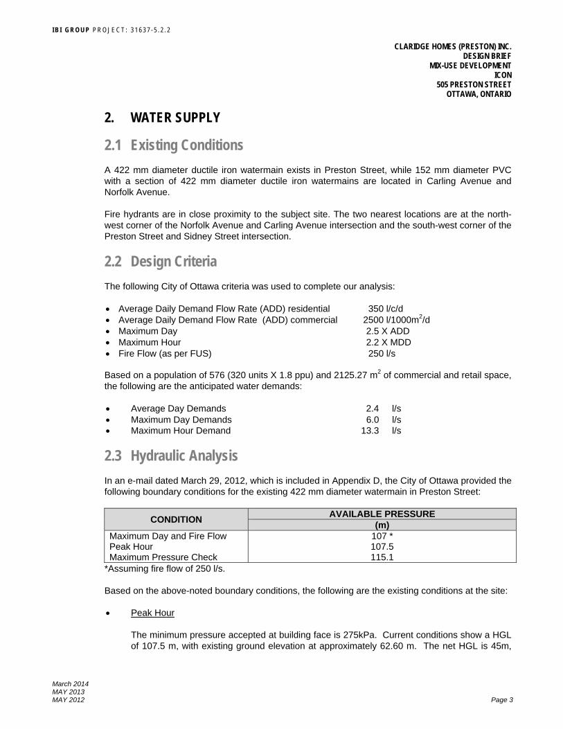
2.3 Hydraulic Analysis
In an e-mail dated March 29, 2012, which is included in Appendix D, the City of Ottawa provided the following boundary conditions for the existing 422 mm diameter watermain in Preston Street:
CONDITION AVAILABLE PRESSURE
(m) Maximum Day and Fire Flow Peak Hour Maximum Pressure Check
107 * 107.5 115.1
*Assuming fire flow of 250 l/s.
Based on the above-noted boundary conditions, the following are the existing conditions at the site:
Peak Hour
The minimum pressure accepted at building face is 275kPa. Current conditions show a HGL of 107.5 m, with existing ground elevation at approximately 62.60 m. The net HGL is 45m,

I B I G R O U P P R O J E C T : 3 1 6 3 7 - 5 . 2 . 2
CLARIDGE HOMES (PRESTON) INC. DESIGN BRIEF
MIX-USE DEVELOPMENT ICON
505 PRESTON STREET OTTAWA, ONTARIO
March 2014 MAY 2013 MAY 2012 Page 4
which yields a peak hour pressure of 441kPa. This pressure exceeds the City’s minimum peak hour criteria.
Fire Flow at Building
The minimum fire flow at Building face is 140 kPa. Current conditions show an HGL of 107.00m for available fire flow, with an existing ground elevation at approximately 62.60 m. The net HGL is 44.5m, which yields a fire flow pressure of 436.1kPa. The resulting pressure exceeds the minimum allowable pressure.
Pressure Reducing Valve
The maximum allowable pressure at the Building face is 552kPa. Current conditions maximum day pressure shows an HGL of 115.1m, with an existing ground elevation of 62.60 m. The net HGL is 52.60m which yields a maximum pressure of 515.5kPa. This pressure is below the maximum allowable; thus, pressure reducing measures are not required.
2.4 Proposed Water Plan
In order to provide the proposed development with a reliable water supply, a new 203 mm diameter water service off the existing 422 mm diameter Norfolk Street watermain is proposed.
In addition, a second 200 mm diameter watermain connection to the 422 mm diameter watermain along Preston Street is proposed in order to ensure adequate fire flow protection via the building’s proposed sprinkler system.
It should be noted that if any existing water services are encountered during construction, the City will be notified and a decision regarding decommissioning of any existing laterals can be discussed.

I B I G R O U P P R O J E C T : 3 1 6 3 7 - 5 . 2 . 2
CLARIDGE HOMES (PRESTON) INC. DESIGN BRIEF
MIX-USE DEVELOPMENT ICON
505 PRESTON STREET OTTAWA, ONTARIO
March 2014 MAY 2013 MAY 2012 Page 5
3. WASTEWATER DISPOSAL
3.1 Existing Conditions
A new 1500 mm diameter concrete combined sewer was constructed as part of the City’s Preston Street Reconstruction project in 2010. These works also included the construction of 2 new combined sewers in Norfolk Avenue, one draining north to a 375 mm diameter combined sewer in Adeline Street and the other draining south to a 1200 mm diameter combined sewer in Carling Avenue.
3.2 Sewer Capacity Analysis
The site is currently a vacant gravel lot. However, the site was once a gas bar which has since been decommissioned and removed. Based on current City criteria for a commercial site, the estimated Pre-development peak wastewater flow from the site is approximately 0.17 l/s.
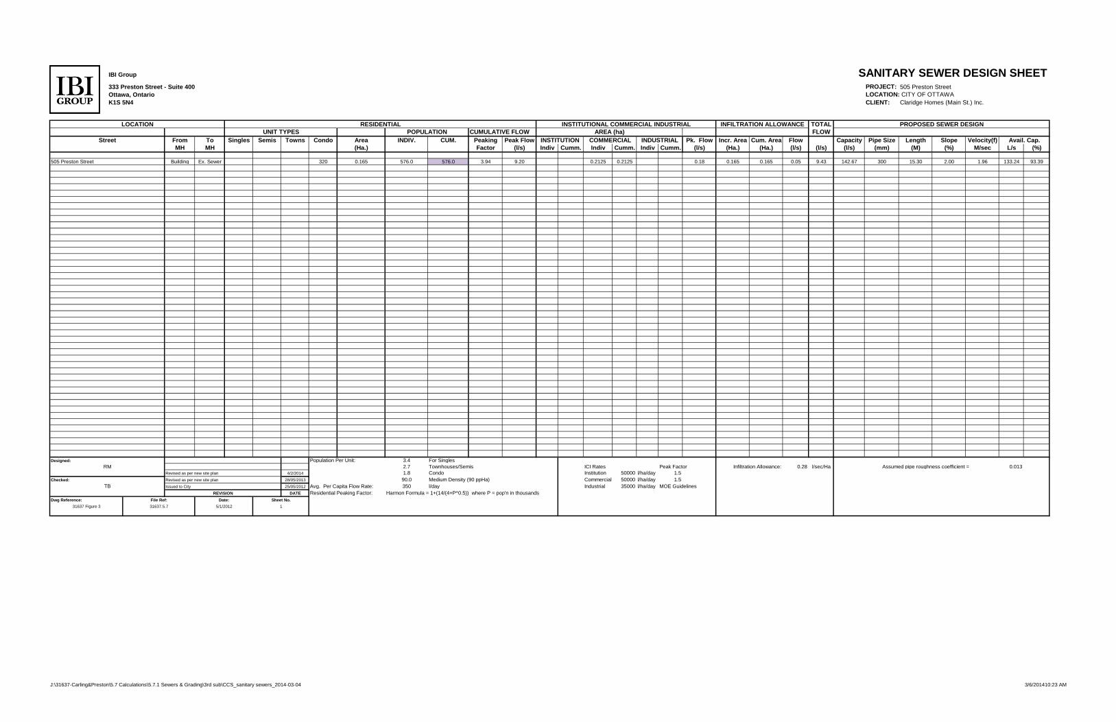
As previously noted, the current proposal will consist of a 45 storey mixed used building with 320 residential units and about 2,125 m2 of commercial/retail space. IBI estimates that the peaked wastewater flow from the proposed development will be 9.43 l/s. This is based on the following criteria:
Total # of units 320 Population density 1.8 ppu Average Residential Flow 350 l/p/d Residential Peaking Factor Harmon Formula [max = 4.0, min. = 2.0] Average Commercial Flow 50,000 l/ha/d Commercial Peaking Factor 1.5
Infiltration Allowance 0.28 l/s/ha
Hence, the theoretical peak sanitary component for the total flow proposed to connect to the existing sewer system is greater than the current flow. However, the City has verbally confirmed that the Preston Street combined sewer could accommodate the projected flows from this development.
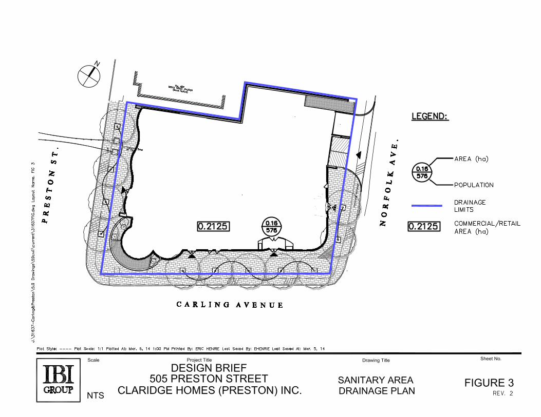
The detailed sewer calculations, together with Figure 3, the Sanitary Drainage Area Plan, are included in Appendix E.
3.3 Proposed Wastewater Plan
A new 300 mm diameter concrete service connection is proposed to be connected to the existing 1500 mm diameter combined sewer in Preston Street. The service will enter the building in the proposed mechanical room. Please refer to the Site Servicing and Grading Plan located in Appendix G.
I B I G R O U P P R O J E C T : 3 1 6 3 7 - 5 . 2 . 2
CLARIDGE HOMES (PRESTON) INC. DESIGN BRIEF
MIX-USE DEVELOPMENT ICON
505 PRESTON STREET OTTAWA, ONTARIO
March 2014 MAY 2013 MAY 2012 Page 6
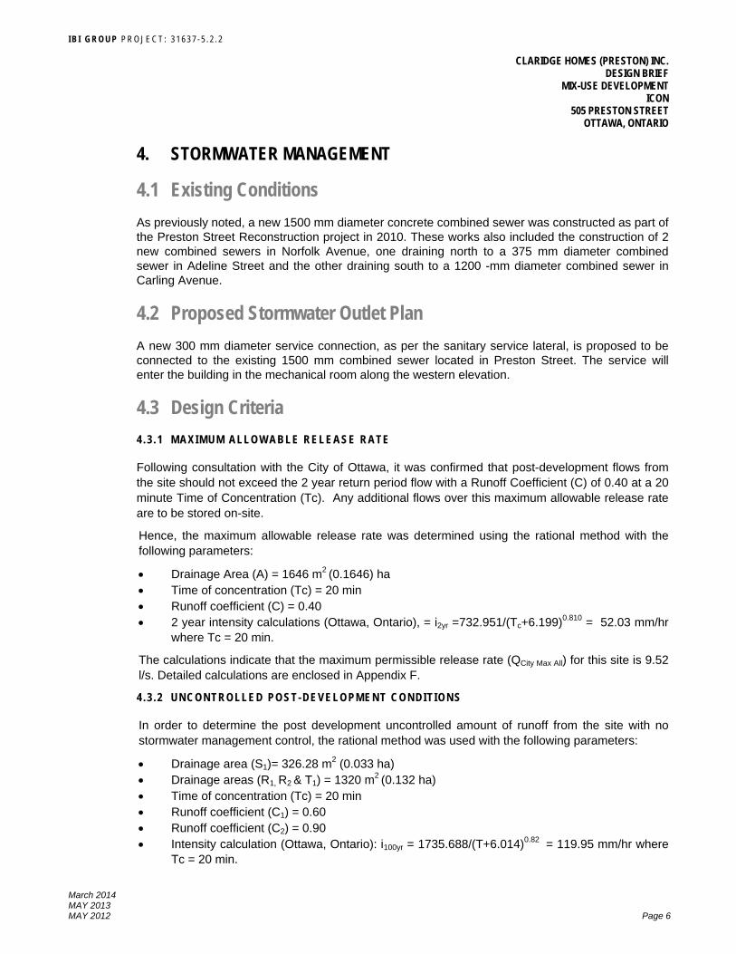
4. STORMWATER MANAGEMENT
4.1 Existing Conditions
As previously noted, a new 1500 mm diameter concrete combined sewer was constructed as part of the Preston Street Reconstruction project in 2010. These works also included the construction of 2 new combined sewers in Norfolk Avenue, one draining north to a 375 mm diameter combined sewer in Adeline Street and the other draining south to a 1200 -mm diameter combined sewer in Carling Avenue.
4.2 Proposed Stormwater Outlet Plan
A new 300 mm diameter service connection, as per the sanitary service lateral, is proposed to be connected to the existing 1500 mm combined sewer located in Preston Street. The service will enter the building in the mechanical room along the western elevation.
4.3 Design Criteria
4 .3 .1 MAXIMUM ALLOWABLE RELEASE RATE
Following consultation with the City of Ottawa, it was confirmed that post-development flows from the site should not exceed the 2 year return period flow with a Runoff Coefficient (C) of 0.40 at a 20 minute Time of Concentration (Tc). Any additional flows over this maximum allowable release rate are to be stored on-site.
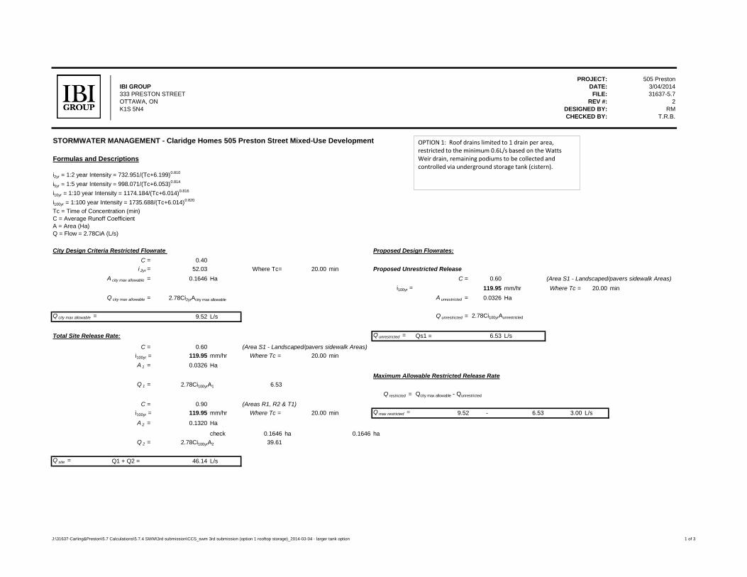
Hence, the maximum allowable release rate was determined using the rational method with the following parameters:
Drainage Area (A) = 1646 m2 (0.1646) ha Time of concentration (Tc) = 20 min Runoff coefficient (C) = 0.40 2 year intensity calculations (Ottawa, Ontario), = i2yr =732.951/(Tc+6.199)0.810 = 52.03 mm/hr
where Tc = 20 min.
The calculations indicate that the maximum permissible release rate (QCity Max All) for this site is 9.52 l/s. Detailed calculations are enclosed in Appendix F.
4 .3 .2 UNCONTROLLED POST-DEVELOPMENT CONDIT IONS
In order to determine the post development uncontrolled amount of runoff from the site with no stormwater management control, the rational method was used with the following parameters:
Drainage area (S1)= 326.28 m2 (0.033 ha) Drainage areas (R1, R2 & T1) = 1320 m2 (0.132 ha) Time of concentration (Tc) = 20 min Runoff coefficient (C1) = 0.60 Runoff coefficient (C2) = 0.90 Intensity calculation (Ottawa, Ontario): i100yr = 1735.688/(T+6.014)0.82 = 119.95 mm/hr where
Tc = 20 min.

I B I G R O U P P R O J E C T : 3 1 6 3 7 - 5 . 2 . 2
CLARIDGE HOMES (PRESTON) INC. DESIGN BRIEF
MIX-USE DEVELOPMENT ICON
505 PRESTON STREET OTTAWA, ONTARIO
March 2014 MAY 2013 MAY 2012 Page 7
The uncontrolled post-development flow rate during the 100 year storm event for the entire site is:
QSite = 46.14 l/s
As the uncontrolled post development flow is greater than the maximum allowable flow, flow attenuation and restriction should be required. The calculations for the rational method can be found in Appendix F
4.4 Water Quantity
The design criteria for this site require that the post-development flow rate be restricted to 9.52 l/s. From the results of the uncontrolled post-development flows for the 100 year storm event, the City of Ottawa’s requirements cannot be met unless some on-site detention is provided.
Following discussions with the Owner and its design team, the site was broken down into 4 Areas, summarized below:
Area S1 represents uncontrolled landscaped sidewalk areas. Areas R1 and R2 represent the two mechanical penthouse roofs. Area T1 represents the uncontrolled terraces and balcony areas.
The locations of the Areas are illustrated in Figure 4. Both the Architect and Mechanical Engineer confirmed that on-site storage is possible via a cistern and ponding on the roofs area of the building.
4 .4 .1 AREA S1 – UNCONTROLLED LANDSCAPED SIDEWALK AREAS
Following discussions with Hariri Pontarini Architects, the runoff generated by Area S1 would be released uncontrolled and captured by the existing combined sewer systems in Norfolk Avenue, Carling Avenue and Preston Street. The Area S1 is 290.47 m2 with an uncontrolled 100 year release rate (Qunc) of 5.81 l/s at a runoff coefficient of 0.60. The location of Area S1 is illustrated in red within Figure 4. Detailed calculations of uncontrolled release rate for Area S1 are presented within Appendix F.
4 .4 .2 AREA R1 –MECHANICAL ROOF
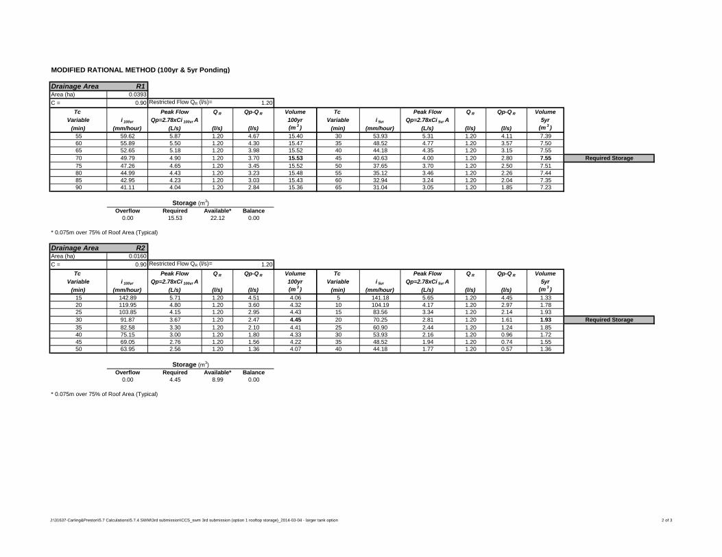
The runoff generated by Area R1 would be released at a controlled rate to the Preston Street combined sewer. The Area is 393.18 m2 with a 100 year restricted rate of 1.2 l/s at a runoff coefficient (c) of 0.90. The location of Area R1 is illustrated on Figure 4 in green. Detailed calculations of the controlled release rate from Area R1 are in Appendix F.
4 .4 .3 AREA R2 – PENTHOUSE/MECHANICAL ROOF
Similarly, the runoff generated by Area R2 would be released at a controlled rate to the Preston Street combined sewer. The Area is 159.82 m2 with a 100 year restricted release rate of 1.2 l/s at a runoff coefficient (c) of 0.90. The location of Area R2 is also illustrated on Figure 4 in blue. Detailed calculations of the controlled release rate from Area R2 is provided in Appendix F.
It should be noted that the average ponding depth for the 2 roof top storage areas noted in the modified rational design sheet in Appendix F are based on the assumption that an average of 0.075 m (3”) is available for 75% of the roof area. A maximum ponding depth of 6” shall be provided by

I B I G R O U P P R O J E C T : 3 1 6 3 7 - 5 . 2 . 2
CLARIDGE HOMES (PRESTON) INC. DESIGN BRIEF
MIX-USE DEVELOPMENT ICON
505 PRESTON STREET OTTAWA, ONTARIO
March 2014 MAY 2013 MAY 2012 Page 8
water relief at scuppers in the parapet. Both the architect and mechanical engineer have confirmed that this is acceptable.
4 .4 .4 AREA T1 – REMAINING ROOF TOP/TERRACE AREAS
The runoff generated by Area T1 would be released uncontrolled to a storage tank (cistern) which, in turn, would gradually release the 100 year contained water at a release rate of 0.60 l/s. The area is 766.72 m2, which includes area from various terraces. The location of Area T1 is illustrated on Figure 4 in yellow.
4.5 Cistern Storage
The runoff generated by Area T1 of 542.33 m2 would be discharged and attenuated into a cistern. Outflow from the cistern would be controlled with an orifice installed in the outlet pipe. The cistern will attenuate the remaining balance of allowable release rate from the site. The balance of the allowable release rate was calculated with the following equation:
Qcistern = ( QCity Max All – QUnrestricted) – ( QAreaR1 + QAreaR2) Qcistern = (9.52 l/s – 6.53 l/s)– (1.2 l/s + 1.2 l/s) = 0.60 l/s
To meet the allowable release rate of 0.60 l/s, the required cistern volume for the 100 year storm event was determined to be 45 m3.
The cistern including orifice will be designed by the Owner’s Mechanical Engineer, Quadrant Engineering Inc. The attenuated flow will be discharged directly into the existing combined sewer system located in Preston Street. Using an overflow pipe, emergency Overflow from the cistern will be directed south to Preston Street.
The stormwater management schematic is enclosed in Appendix F.
4.6 Stormwater Management Summary
The maximum allowable release rate is 9.52 l/s with the 2 year flow at a runoff coefficient of 0.40. Rooftop storage and a cistern would be provided to meet the City of Ottawa requirements.
The flow from Area S1 would discharge into the existing combined sewer system on Norfolk Avenue, Carling Avenue and Preston Street with an unrestricted flow rate of 6.53 l/s.
The flow from Areas R1 and R2 would discharge into the existing combined sewer system on Preston Street with a restricted flow rate of 1.20 l/s each.
The flow from Area T1 would be controlled at a flow rate of 0.60 l/s. During the 100 year storm event, 45 m3 would be stored in the cistern. The attenuated flow will discharge directly into the combined sewer system on Preston Street.

I B I G R O U P P R O J E C T : 3 1 6 3 7 - 5 . 2 . 2
CLARIDGE HOMES (PRESTON) INC. DESIGN BRIEF
MIX-USE DEVELOPMENT ICON
505 PRESTON STREET OTTAWA, ONTARIO
March 2014 MAY 2013 MAY 2012 Page 9
5. STORMWATER SITE MANAGEMENT
During construction, existing conveyance systems can be exposed to significant sediment loadings. Although construction is only a temporary situation, it is proposed to introduce a number of mitigative construction techniques to reduce unnecessary construction sediment loadings. These will include:
In trench groundwater will be pumped into a filter mechanism prior to release to the environment. Pumping in excess of 50,000 l/day will require a Permit To Take Water from the provincial Ministry of Environment. The geotechnical report will review this issue.
Filter cloths will be placed on open structures such as catchbasins and manhole covers, and will remain in place until the project is completed. Regular monitoring will be required to ensure proper function of the cloth including replacement as required.
Existing catchbasins on the streets adjacent to the streets are to be monitored to ensure that their sumps remain clean (cleaned as required).

I B I G R O U P P R O J E C T : 3 1 6 3 7 - 5 . 2 . 2
CLARIDGE HOMES (PRESTON) INC. DESIGN BRIEF
MIX-USE DEVELOPMENT ICON
505 PRESTON STREET OTTAWA, ONTARIO
March 2014 MAY 2013 MAY 2012 Page 10
6. APPROVALS AND PERMIT REQUIREMENTS
6.1 City of Ottawa
The City of Ottawa reviews all development documents including this report. Upon completion, the City will approve the service connections, submit the Stormwater Management MOE application to the province and eventually issue a Commence Work Notification.
6.2 Province of Ontario
Because the sewers services are proposed to be connected to a combined sewer, the Ministry of Environment (MOE) will need to formally approve the sewer connections and proposed stormwater management plan. If needed, the MOE will also issue a Permit To Take Water.
6.3 Conservation Authority
There are no approvals required from any Conservation Authority for this project.
6.4 Federal Government
There are no required permits, authorizations or approvals needed expressly for this development.


APPENDIX A

Genera l Conten t
ITEM DESCRIPTION
LOCATION
Executive Summary (for larger reports only) N/A √ Date and revision number of the report Front Cover √ Location Map and plan showing municipal address, boundary, and
layout of proposed development. Figure 1 and 2
√ Plan showing the site and location of all existing services. Drawing C-100 √ Development statistics, land use, density, adherence to zoning and
official plan, and reference to applicable subwatershed and watershed plans that provide context to which individual developments must adhere.
Section 1.3
√ Summary of Pre-consultation Meeting with City and other approval agencies.
Section 4.3, Appendix C
Reference and confirm conformance to higher level studies and reports (Master Servicing Studies, Environmental Assessments, Community Design Plans), or in the case where it is not in conformance, the proponent must provide justification and develop a defendable design criteria.
N/A
Statement of objectives and servicing criteria Section 2.2, 3.2, 4.3, Appendix C
√ Identification of existing and proposed infrastructure available in the immediate area.
Section 2.1, 3.1, 4.1
Identification of Environmentally Significant Areas, Watercourses and Municipal Drains potentially impacted by the proposed development (Reference can be made to the Natural Heritage Studies, if available).
N/A
Concept level master grading plan to confirm existing and proposed grades in the development. This is required to confirm the feasibility of proposed stormwater management and drainage, soil removal and fill constraints, and potential impacts to neighbouring properties. This is also required to confirm that the proposed grading will not impede existing major system flow paths.
N/A
Identification of potential impacts of proposed piped services on private services (such as wells and septic fields on adjacent lands) and mitigation required to address potential impacts.
N/A
Proposed phasing of the development, if applicable. N/A √ Reference to geotechnical studies and recommendations
concerning servicing. Section 1.5
√ All preliminary and formal site plan submissions should have the following information: • Metric scale • North arrow (including construction North) • Key plan • Name and contact information of applicant and property owner • Property limits including bearings and dimensions • Existing and proposed structures and parking areas • Easements, road widening and rights-of-way • Adjacent street names
Report Drawings

Deve lopment Servic ing Report: Wate r
ITEM DESCRIPTION
LOCATION
Confirm consistency with Master Servicing Study, if available N/A √ Availability of public infrastructure to service proposed development Section 2.1 Identification of system constraints – external water needed N/A √ Identify boundary conditions Appendix D √ Confirmation of adequate domestic supply and pressure Section 2.4 √ Confirmation of adequate fire flow protection and confirmation that
fire flow is calculated as per the Fire Underwriter’s Survey. Output should show available fire flow at locations throughout the development.
Section 2.2
√ Provide a check of high pressures. If pressure is found to be high, an assessment is required to confirm the application of pressure reducing valves.
Section 2.3
Definition of phasing constraints. Hydraulic modeling is required to confirm servicing for all defining phases of the project including the ultimate design.
N/A
Address reliability requirements such as appropriate location of shut-off valves. N/A
Check on the necessity of a pressure zone boundary modification. N/A √ Reference to water supply analysis to show that major infrastructure
is capable of delivering sufficient water for the proposed land use. This includes data that shows that the expected demands under average day, peak hour and fire flow conditions provide water within the required pressure range.
Section 2.3
Description of the proposed water distribution network, including locations of proposed connections to the existing system, provisions for necessary looping, and appurtenances (valves, pressure reducing valves, valve chambers, and fire hydrants) including special metering provisions.
N/A
Description of off-site required feedermains, booster pumping stations, and other water infrastructure that will be ultimately required to service proposed development, including financing, interim facilities and timing of implementation.
N/A
√ Confirmation that water demands are calculated based on the City of Ottawa Design Guidelines. Section 2.2
Provision of a model schematic showing the boundary conditions locations, streets, parcels, and building locations for reference. N/A

Deve lopment Servic ing Report: Was tewate r
ITEM DESCRIPTION
LOCATION
√ Summary of proposed design criteria (Note: Wet-weather flow
criteria should not deviate from the City of Ottawa Sewer Design Guidelines. Monitored flow data from relatively new infrastructure cannot be used to justify capacity requirements for proposed infrastructure).
Section 3.2 and
Appendix C
Confirm consistency with Master Servicing Study and/or justifications for deviations. N/A
Consideration of local conditions that may contribute to extraneous flows that are higher than the recommended flows in the guidelines. This includes groundwater and soil conditions, and age condition of sewers.
N/A
√ Description of existing sanitary sewer available for discharge of wastewater from proposed development. Section 3.1
√ Verify available capacity in downstream sanitary sewer and/or identification of upgrades necessary to service the proposed development. (Reference can be made to previously completed Master Servicing Study if applicable)
Section 3.2
√ Calculations related to dry-weather and wet-weather flow rates from the development in standard MOE sanitary sewer design table (Appendix “C”) format.
Appendix E
√ Description of proposed sewer network including sewers, pumping stations and forcemains. Section 3.3
Discussion of previously identified environmental constraints and impact on servicing (environmental constraints are related to limitations imposed on the development in order to preserve the physical condition of watercourses, vegetation, soil cover, as well as protecting against water quantity and quality).
N/A
Pumping stations: impacts of proposed development on existing pumping stations or requirements for new pumping station to service development.
N/A
Forcemain capacity in terms of operational redundancy, surge pressure and maximum flow velocity. N/A
Identification and implementation of the emergency overflow from sanitary pumping stations in relation to the hydraulic grade line to protect against basement flooding.
N/A
√ Special considerations such as contamination, corrosive environment, check soils, etc. Section 1.5

Deve lopment Servic ing Report: S tormwate r Checklis t
ITEM DESCRIPTION
LOCATION
√ Description of drainage outlets and downstream constraints
including legality of outlets (i.e. municipal drain, right-of-way, watercourse, or private property)
N/A
√ Analysis of available capacity in existing public infrastructure. Appendix C A drawing showing the subject lands, its surroundings, the receiving
watercourse, existing drainage patterns, and proposed drainage pattern.
N/A
Water quantity control objective (e.g. controlling post-development peak flows to pre-development level for storm events ranging from the 2 or 5 year event (dependent on the receiving sewer design) to 100 year return period); if other objectives are being applied, a rationale must be included with reference to hydrologic analyses of the potentially affected subwatersheds, taking into account long-term cumulative effects.
Section 4.4
Water quality control objective (basic, normal or enhanced level of protection based on the sensitivities of the receiving watercourse) and storage requirements.
N/A
Description of the stormwater management concept with facility locations and descriptions with references and supporting information.
Section 4
Set-back from private sewage disposal systems. N/A Watercourse and hazard lands setbacks. N/A Record of pre-consultation with the Ontario Ministry of Environment
and the Conservation Authority that has jurisdiction on the affected watershed.
N/A
Confirm consistency with sub-watershed and Master Servicing Study, if applicable study exists. N/A
√ Storage requirements (complete with calculations) and conveyance capacity for minor events (1:5 year return period) and major events (1:100 year return period).
Section 4.4, Appendix F
Identification of watercourses within the proposed development and how watercourses will be protected, or, if necessary, altered by the proposed development with applicable approvals.
N/A
√ Calculate pre and post development peak flow rates including a description of existing site conditions and proposed impervious areas and drainage catchments in comparison to existing conditions.
Section 4.3. 4.4
Any proposed diversion of drainage catchment areas from one outlet to another. N/A
Proposed minor and major systems including locations and sizes of stormwater trunk sewers, and stormwater management facilities. N/A
If quantity control is not proposed, demonstration that downstream system has adequate capacity for the post-development flows up to and including the 100-year return period storm event.
N/A
Identification of potential impacts to receiving watercourses N/A Identification of municipal drains and related approval requirements. N/A √ Descriptions of how the conveyance and storage capacity will be
achieved for the development. Section 4.4
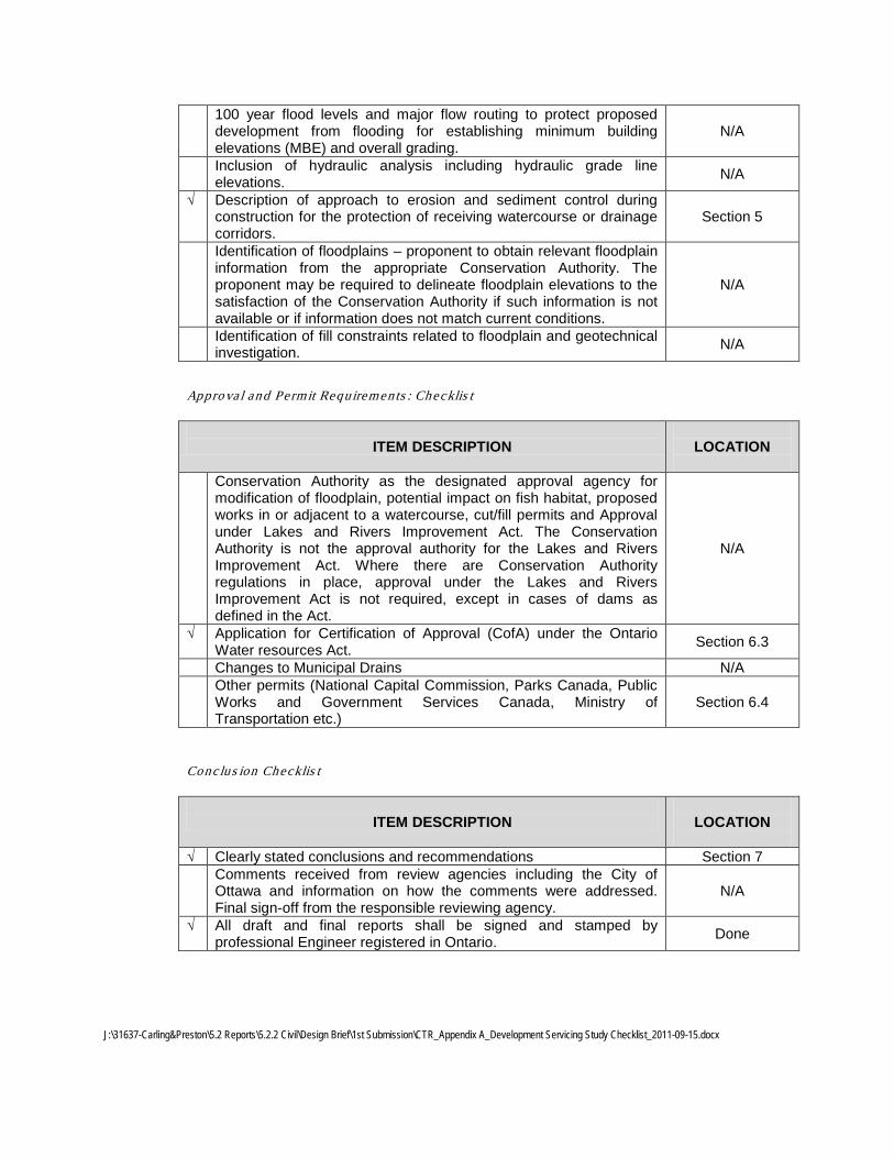
100 year flood levels and major flow routing to protect proposed development from flooding for establishing minimum building elevations (MBE) and overall grading.
N/A
Inclusion of hydraulic analysis including hydraulic grade line elevations. N/A
√ Description of approach to erosion and sediment control during construction for the protection of receiving watercourse or drainage corridors.
Section 5
Identification of floodplains – proponent to obtain relevant floodplain information from the appropriate Conservation Authority. The proponent may be required to delineate floodplain elevations to the satisfaction of the Conservation Authority if such information is not available or if information does not match current conditions.
N/A
Identification of fill constraints related to floodplain and geotechnical investigation. N/A
Appro va l and Permit Requirements : Checklis t
ITEM DESCRIPTION
LOCATION
Conservation Authority as the designated approval agency for
modification of floodplain, potential impact on fish habitat, proposed works in or adjacent to a watercourse, cut/fill permits and Approval under Lakes and Rivers Improvement Act. The Conservation Authority is not the approval authority for the Lakes and Rivers Improvement Act. Where there are Conservation Authority regulations in place, approval under the Lakes and Rivers Improvement Act is not required, except in cases of dams as defined in the Act.
N/A
√ Application for Certification of Approval (CofA) under the Ontario Water resources Act. Section 6.3
Changes to Municipal Drains N/A Other permits (National Capital Commission, Parks Canada, Public
Works and Government Services Canada, Ministry of Transportation etc.)
Section 6.4
Conc lus ion Checklis t
ITEM DESCRIPTION
LOCATION
√ Clearly stated conclusions and recommendations Section 7 Comments received from review agencies including the City of
Ottawa and information on how the comments were addressed. Final sign-off from the responsible reviewing agency.
N/A
√ All draft and final reports shall be signed and stamped by professional Engineer registered in Ontario. Done
J:\31637-Carling&Preston\5.2 Reports\5.2.2 Civil\Design Brief\1st Submission\CTR_Appendix A_Development Servicing Study Checklist_2011-09-15.docx

APPENDIX B


APPENDIX C


APPENDIX D


APPENDIX E
IBI Group SANITARY SEWER DESIGN SHEET333 Preston Street - Suite 400 PROJECT: The Meadows of Half Moon Bay Phases 1A, 1B & 2A505 Preston StreetOttawa, Ontario LOCATION: CITY OF OTTAWAK1S 5N4 CLIENT: Claridge Homes (Main St.) Inc.
TOTALCUMULATIVE FLOW FLOW
From To Singles Semis Towns Condo Area INDIV. CUM. Peaking Peak Flow Pk. Flow Incr. Area Cum. Area Flow Capacity Pipe Size Length Slope Velocity(f)MH MH (Ha.) Factor (l/s) Indiv Cumm. Indiv Cumm. Indiv Cumm. (l/s) (Ha.) (Ha.) (l/s) (l/s) (l/s) (mm) (M) (%) M/sec L/s (%)
505 Preston Street Building Ex. Sewer 320 0.165 576.0 576.0 3.94 9.20 0.2125 0.2125 0.18 0.165 0.165 0.05 9.43 142.67 300 15.30 2.00 1.96 133.24 93.39
Population Per Unit: 3.4 For Singles2.7 Townhouses/Semis ICI Rates Peak Factor Infiltration Allowance: 0.28 l/sec/Ha Assumed pipe roughness coefficient = 0.013
4/2/2014 1.8 Condo Institution 50000 l/ha/day 1.528/05/2013 90.0 Medium Density (90 ppHa) Commercial 50000 l/ha/day 1.525/05/2012 Avg. Per Capita Flow Rate: 350 l/day Industrial 35000 l/ha/day MOE Guidelines
DATE Residential Peaking Factor: Harmon Formula = 1+(14/(4+P^0.5)) where P = pop'n in thousands
1
Checked:
5/1/201231637.5.731637 Figure 3Date: Sheet No.
REVISIONTB
Dwg Reference: File Ref:
Issued to City
Avail. Cap.
INSTITUTIONAL COMMERCIAL INDUSTRIAL INFILTRATION ALLOWANCELOCATIONAREA (ha)
INSTITUTION COMMERCIAL INDUSTRIAL
PROPOSED SEWER DESIGNUNIT TYPES
Street
RESIDENTIAL
Revised as per new site plan
POPULATION
Designed:RM
Revised as per new site plan
J:\31637-Carling&Preston\5.7 Calculations\5.7.1 Sewers & Grading\3rd sub\CCS_sanitary sewers_2014-03-04 3/6/201410:23 AM

APPENDIX F

PROJECT: 505 PrestonIBI GROUP DATE: 3/04/2014333 PRESTON STREET FILE: 31637-5.7OTTAWA, ON REV #: 2K1S 5N4 DESIGNED BY: RM
CHECKED BY: T.R.B.
STORMWATER MANAGEMENT - Claridge Homes 505 Preston Street Mixed-Use Development
Formulas and Descriptions
i2yr = 1:2 year Intensity = 732.951/(Tc+6.199)0.810
i5yr = 1:5 year Intensity = 998.071/(Tc+6.053)0.814
i10yr = 1:10 year Intensity = 1174.184/(Tc+6.014)0.816
i100yr = 1:100 year Intensity = 1735.688/(Tc+6.014)0.820
Tc = Time of Concentration (min)C = Average Runoff CoefficientA = Area (Ha)Q = Flow = 2.78CiA (L/s)
City Design Criteria Restricted Flowrate Proposed Design Flowrates:
C = 0.40i 2yr = 52.03 Where Tc= 20.00 min Proposed Unrestricted Release
A city max allowable = 0.1646 Ha C = 0.60 (Area S1 - Landscaped/pavers sidewalk Areas)
i100yr = 119.95 mm/hr Where Tc = 20.00 minQ city max allowable = A unrestricted = 0.0326 Ha
Q city max allowable = 9.52 L/s Q unrestricted = 2.78Ci100yrAunrestricted
Total Site Release Rate: Q unrestricted = Qs1 = 6.53 L/s
C = 0.60 (Area S1 - Landscaped/pavers sidewalk Areas)
119.95 mm/hr Where Tc = 20.00 minA 1 = 0.0326 Ha
Maximum Allowable Restricted Release Rate
Q 1 = 6.53Q restricted = Qcity max allowable - Qunrestricted
C = 0.90 (Areas R1, R2 & T1)
119.95 mm/hr Where Tc = 20.00 min Q max restricted = 9.52 - 6.53 3.00 L/sA 2 = 0.1320 Ha
check 0.1646 ha 0.1646 haQ 2 = 39.61
Q site = Q1 + Q2 = 46.14 L/s
2.78Ci2yrAcity max allowable
i100yr =
2.78Ci100yrA2
i100yr =
2.78Ci100yrA1
OPTION 1: Roof drains limited to 1 drain per area, restricted to the minimum 0.6L/s based on the Watts Weir drain, remaining podiums to be collected and controlled via underground storage tank (cistern).
J:\31637-Carling&Preston\5.7 Calculations\5.7.4 SWM\3rd submission\CCS_swm 3rd submission (option 1 rooftop storage)_2014-03-04 - larger tank option 1 of 3
MODIFIED RATIONAL METHOD (100yr & 5yr Ponding)
Drainage Area R1Area (ha) 0.0393C = 0.90 Restricted Flow QR (l/s)= 1.20
Tc Peak Flow Q R Qp-Q R Volume Tc Peak Flow Q R Qp-Q R Volume
Variable i 100yr Qp=2.78xCi 100yr A 100yr Variable i 5yr Qp=2.78xCi 5yr A 5yr
(min) (mm/hour) (L/s) (l/s) (l/s) (m3) (min) (mm/hour) (L/s) (l/s) (l/s) (m
3)
55 59.62 5.87 1.20 4.67 15.40 30 53.93 5.31 1.20 4.11 7.3960 55.89 5.50 1.20 4.30 15.47 35 48.52 4.77 1.20 3.57 7.5065 52.65 5.18 1.20 3.98 15.52 40 44.18 4.35 1.20 3.15 7.5570 49.79 4.90 1.20 3.70 15.53 45 40.63 4.00 1.20 2.80 7.5575 47.26 4.65 1.20 3.45 15.52 50 37.65 3.70 1.20 2.50 7.5180 44.99 4.43 1.20 3.23 15.48 55 35.12 3.46 1.20 2.26 7.4485 42.95 4.23 1.20 3.03 15.43 60 32.94 3.24 1.20 2.04 7.3590 41.11 4.04 1.20 2.84 15.36 65 31.04 3.05 1.20 1.85 7.23
Overflow Required Available* Balance0.00 15.53 22.12 0.00
* 0.075m over 75% of Roof Area (Typical)
Drainage Area R2Area (ha) 0.0160C = 0.90 Restricted Flow QR (l/s)= 1.20
Tc Peak Flow Q R Qp-Q R Volume Tc Peak Flow Q R Qp-Q R Volume
Variable i 100yr Qp=2.78xCi 100yr A 100yr Variable i 5yr Qp=2.78xCi 5yr A 5yr
(min) (mm/hour) (L/s) (l/s) (l/s) (m3) (min) (mm/hour) (L/s) (l/s) (l/s) (m
3)
15 142.89 5.71 1.20 4.51 4.06 5 141.18 5.65 1.20 4.45 1.3320 119.95 4.80 1.20 3.60 4.32 10 104.19 4.17 1.20 2.97 1.7825 103.85 4.15 1.20 2.95 4.43 15 83.56 3.34 1.20 2.14 1.9330 91.87 3.67 1.20 2.47 4.45 20 70.25 2.81 1.20 1.61 1.9335 82.58 3.30 1.20 2.10 4.41 25 60.90 2.44 1.20 1.24 1.8540 75.15 3.00 1.20 1.80 4.33 30 53.93 2.16 1.20 0.96 1.7245 69.05 2.76 1.20 1.56 4.22 35 48.52 1.94 1.20 0.74 1.5550 63.95 2.56 1.20 1.36 4.07 40 44.18 1.77 1.20 0.57 1.36
Overflow Required Available* Balance0.00 4.45 8.99 0.00
* 0.075m over 75% of Roof Area (Typical)
Storage (m3)
Storage (m3)
Required Storage
Required Storage
J:\31637-Carling&Preston\5.7 Calculations\5.7.4 SWM\3rd submission\CCS_swm 3rd submission (option 1 rooftop storage)_2014-03-04 - larger tank option 2 of 3

Drainage Area T1Area (ha) 0.0767C = 0.90 Restricted Flow QR (l/s)= 0.60
Tc Peak Flow Q R Qp-Q R Volume Tc Peak Flow Q R Qp-Q R Volume
Variable i 100yr Qp=2.78xCi 100yr A 100yr Variable i 5yr Qp=2.78xCi 5yr A 5yr
(min) (mm/hour) (L/s) (l/s) (l/s) (m3) (min) (mm/hour) (L/s) (l/s) (l/s) (m
3)
285 16.56 3.18 0.60 2.58 44.14 165 15.18 2.91 0.60 2.32 22.94290 16.33 3.13 0.60 2.54 44.15 170 14.83 2.85 0.60 2.25 22.95295 16.11 3.09 0.60 2.49 44.15 175 14.50 2.78 0.60 2.19 22.95300 15.89 3.05 0.60 2.45 44.16 180 14.18 2.72 0.60 2.12 22.95305 15.68 3.01 0.60 2.41 44.15 185 13.88 2.66 0.60 2.07 22.94310 15.48 2.97 0.60 2.37 44.15 190 13.59 2.61 0.60 2.01 22.93315 15.28 2.93 0.60 2.34 44.15 195 13.31 2.55 0.60 1.96 22.91320 15.09 2.89 0.60 2.30 44.14 200 13.05 2.50 0.60 1.91 22.89
Overflow Required Available Balance0.00 44.16 45.00 0.00 To be captured via in-building storage tank
Required Storage
Storage (m3)
J:\31637-Carling&Preston\5.7 Calculations\5.7.4 SWM\3rd submission\CCS_swm 3rd submission (option 1 rooftop storage)_2014-03-04 - larger tank option 3 of 3


STORM SEWERS
IBI Group STORM SEWER DESIGN SHEET333 Preston Street - Suite 400 PROJECT: 505 PrstonOttawa, Ontario LOCATION: City of OttawaK1S 5N4 CLIENT: Clardige Homes ( Preston Street) Inc.
STREET DRAINAGE FROM TO C= C= C= C= C= C= C= INDIV. ACCUM. INLET TIME TOTAL I PEAK CAP. LENGTH PIPE SLOPE VEL.AREA ID MH MH 0.20 0.45 0.49 0.60 0.64 0.80 0.90 2.78AC 2.78AC (min.) IN PIPE (min.) (mm/Hr) FLOW (L/s) (L/s) (M) (mm) (%) (M/s) (L/s) (%)
505 Preston Street Building Ex. Sewer 0.033 0.1320 0.38 0.38 20.00 0.13 20.13 70.25 27.02 142.67 15.30 300 2.00 1.955 115.65 81.06%
Designed:Q = 2.78AIC, where: Mannings Coefficient (n) = 0.013Q = Peak Flow in Litres per Second (l/s)
Checked: A = Area in Hectares (ha.)I = Rainfall Intensity in Millimeters per Hour (mm/hr) [I=998.071/(TC+6.053)0.814]
Dwg. Reference:
AVAIL. CAP. (1)
Revision Date
revised as per new site plan 41793.00
LOCATION AREA (Ha) RATIONAL DESIGN FLOW SEWER DATA
RM
31637 Figure 4 31637- 5.7 25/05/2012 1 of 1
TB revised as per new site plan 28/05/2013
File Ref: Date: Sheet No:

APPENDIX G