Design Basis for Water Impounding Concrete Bulkhead, … · Bulkhead Design Basis 3 May 18, 2015...
38
1313 Sherman Street, Room 215, Denver, CO 80203 P 303.866.3567 F 303.832.8106 http://mining.state.co.us John W. Hickenlooper, Governor | Mike King, Executive Director | Virginia Brannon, Director DATE: May 18, 2015 (Portions Updated September 17, 2015) BY: Allen Sorenson and Kirstin Brown RE: Design Basis for Water Impounding Concrete Bulkhead, Red and Bonita Mine, San Juan County Colorado Background The Red and Bonita mine adit is located ten miles north of the Town of Silverton on the east side of the valley of Cement Creek. The Red and Bonita adit drains the mine workings and surrounding rock with a discharge at the portal measured at 336 gallons per minute (gpm) in May 2009. Subsequent flow measurements from the adit are 180 gpm in April 2010, 314 gpm in May 2012, 202 gpm in October 2012, and 197 gpm in May 2013. In July of 2015, the discharge was consistently in excess of 500 gpm. On August 13, 2015 the discharge was measured at 400 gpm. The source of the water draining from the Red and Bonita adit is likely from a relatively permeable rock fracture zone or zones intersected by the adit more than 1000 feet east of the portal. Red and Bonita drainage is one of the primary sources of heavy metal loading to Cement Creek and the Animas River. The Red and Bonita discharge pH measured in 2009-2011 is slightly acidic and the dissolved metals carried by the discharge are derived by acid rock drainage (ARD) mechanisms through the oxidation of sulfide minerals. After the collapsed portal was reopened by the U.S. Environmental Protection Agency (EPA) in 2011, the pH of the adit discharge became more acidic, exhibiting a pH of between four and five standard units during the summer of 2012. It has also been observed that the pH of the adit discharge drops when metal oxy-hydroxide sediments and precipitates are stirred-up by activities within the mine. Otherwise, the pH of the mine water has ranged from a low of 5.31 to a high of 6.06 standard units over the course of nine sampling event from September of 2010 to May of 2013. Water impounding concrete bulkheads installed at strategic locations in draining and discharging underground mine workings have the potential to flood the workings and create a mine pool that will eventually establish a ground water system with water table and flow paths similar to the pre-mining system. Saturation of sulfide minerals in the flooded workings and country rock will create relatively anoxic conditions and limit the generation of ARD. Bulkhead installation will 1313 Sherman Street, Room 215 Denver, CO 80203
-
Upload
vuongduong -
Category
Documents
-
view
217 -
download
0
Transcript of Design Basis for Water Impounding Concrete Bulkhead, … · Bulkhead Design Basis 3 May 18, 2015...

1313 Sherman Street, Room 215, Denver, CO 80203 P 303.866.3567 F 303.832.8106 http://mining.state.co.us
John W. Hickenlooper, Governor | Mike King, Executive Director | Virginia Brannon, Director
DATE: May 18, 2015 (Portions Updated September 17, 2015)
BY: Allen Sorenson and Kirstin Brown
RE: Design Basis for Water Impounding Concrete Bulkhead,
Red and Bonita Mine, San Juan County Colorado
Background
The Red and Bonita mine adit is located ten miles north of the Town of Silverton on the east side
of the valley of Cement Creek. The Red and Bonita adit drains the mine workings and
surrounding rock with a discharge at the portal measured at 336 gallons per minute (gpm) in May
2009. Subsequent flow measurements from the adit are 180 gpm in April 2010, 314 gpm in May
2012, 202 gpm in October 2012, and 197 gpm in May 2013. In July of 2015, the discharge was
consistently in excess of 500 gpm. On August 13, 2015 the discharge was measured at 400 gpm.
The source of the water draining from the Red and Bonita adit is likely from a relatively
permeable rock fracture zone or zones intersected by the adit more than 1000 feet east of the
portal. Red and Bonita drainage is one of the primary sources of heavy metal loading to Cement
Creek and the Animas River.
The Red and Bonita discharge pH measured in 2009-2011 is slightly acidic and the dissolved
metals carried by the discharge are derived by acid rock drainage (ARD) mechanisms through
the oxidation of sulfide minerals. After the collapsed portal was reopened by the U.S.
Environmental Protection Agency (EPA) in 2011, the pH of the adit discharge became more
acidic, exhibiting a pH of between four and five standard units during the summer of 2012. It
has also been observed that the pH of the adit discharge drops when metal oxy-hydroxide
sediments and precipitates are stirred-up by activities within the mine. Otherwise, the pH of the
mine water has ranged from a low of 5.31 to a high of 6.06 standard units over the course of nine
sampling event from September of 2010 to May of 2013.
Water impounding concrete bulkheads installed at strategic locations in draining and discharging
underground mine workings have the potential to flood the workings and create a mine pool that
will eventually establish a ground water system with water table and flow paths similar to the
pre-mining system. Saturation of sulfide minerals in the flooded workings and country rock will
create relatively anoxic conditions and limit the generation of ARD. Bulkhead installation will
1313 Sherman Street, Room 215
Denver, CO 80203

Bulkhead Design Basis 2 May 18, 2015
Red and Bonita Mine
eliminate rapid and continuous collection and discharge of ground water though open mine
workings and minimize direct discharge of ARD from mine portals. Bulkheads serve to smooth
mine discharge hydrographs by returning ground water flow paths to low velocity, low gradient
fracture flow or porous media pathways. Bulkheads further serve to prevent periodic surge
releases, or blowout type releases of ground water backed up behind collapses and ice dams that
are characteristic of abandoned and unmaintained draining mines. Bulkhead installation in
mines that are determined to be good candidates has the potential to significantly reduce metal
loading to receiving streams.
During 2013 and 2014, the EPA and the Colorado Inactive Mine Reclamation Program (CIRMP)
conducted investigations of the feasibility to install a water impounding concrete bulkhead in the
Red and Bonita adit. As a result of those investigations, EPA will be installing a bulkhead into
the adit in 2015, and has tasked CIMRP to assist in the design of the bulkhead. The objective of
the bulkhead is reduction in metal loading to Cement Creek and the Upper Animas River caused
by dissolved metals in the Red and Bonita mine drainage.
Mine Drainage into Cement Creek
Multiple bulkheads have previously been installed in mine workings in the vicinity of the Red
and Bonita mine. Notably, since bulkheads were installed in the American Tunnel in the 1990s
and early 2000s, the American Tunnel being located approximately one-half mile south and 330
feet lower in elevation than the Red and Bonita workings, the flow at the Red and Bonita portal
has increased from a negligible discharge to the present levels that are frequently in excess of
300 gpm. A review of mine drainage and previous mine drainage management activities is
contained in this section.
The American Tunnel portal is east of Cement Creek at the town site of Gladstone (Figures 1a, b,
and c). This tunnel started as the Gold King Tunnel in 1900, and was intended to undercut the
Gold King mine vein system, but raises from the tunnel up to the Gold King were never
constructed. In 1959, the tunnel was renamed the American Tunnel and driven to a total length
of two miles to undercut the Sunnyside Mine and serve as the mine’s primary haulage way. By
February of 1961, the American Tunnel was gravity draining the Sunnyside Mine, which had
flooded to an elevation of 11,500 feet, approximately fifty feet below the F-level of the mine,
during the preceding twenty-plus years of inactivity (Simon Hydro-Search, 1993).
Prior to August of 1996, the primary source of mine drainage to Cement Creek was from the
American Tunnel. The portal elevation of the American Tunnel is 10,617 feet. Measurement of
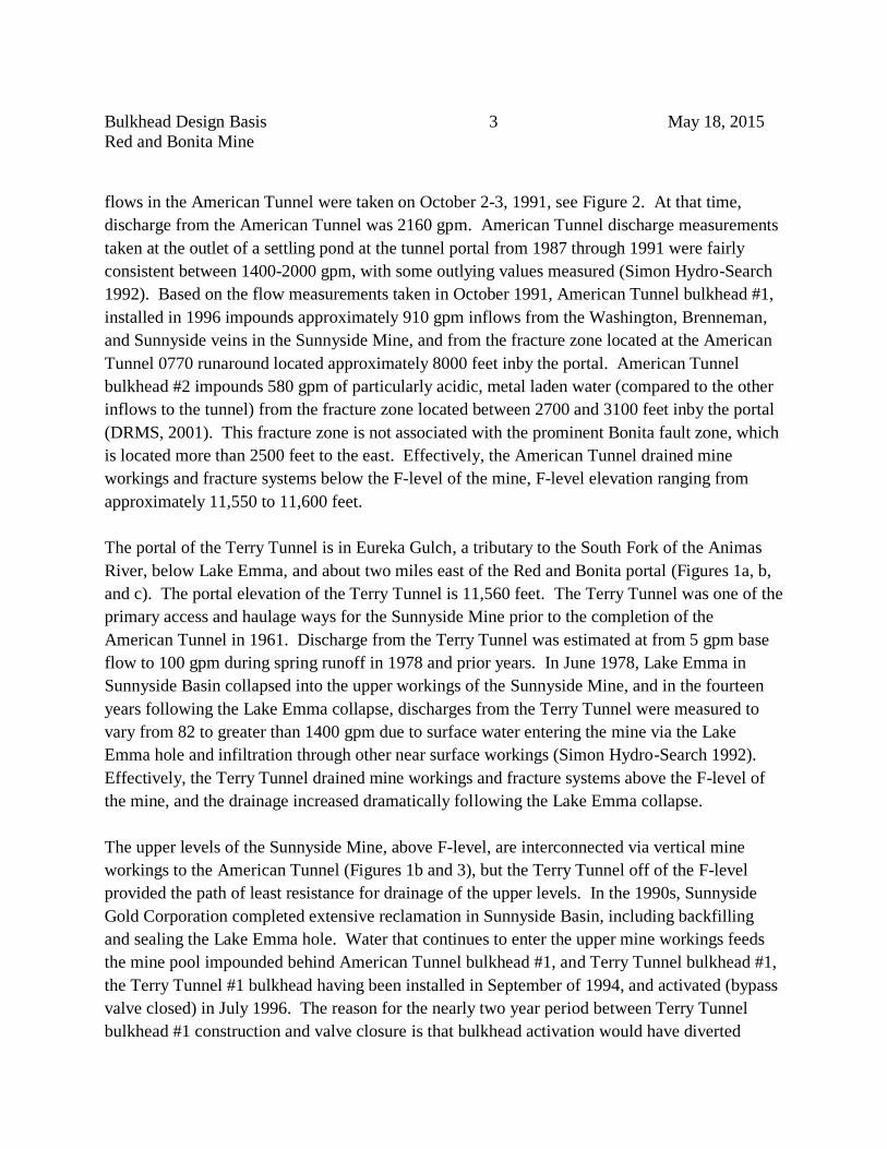
Bulkhead Design Basis 3 May 18, 2015
Red and Bonita Mine
flows in the American Tunnel were taken on October 2-3, 1991, see Figure 2. At that time,
discharge from the American Tunnel was 2160 gpm. American Tunnel discharge measurements
taken at the outlet of a settling pond at the tunnel portal from 1987 through 1991 were fairly
consistent between 1400-2000 gpm, with some outlying values measured (Simon Hydro-Search
1992). Based on the flow measurements taken in October 1991, American Tunnel bulkhead #1,
installed in 1996 impounds approximately 910 gpm inflows from the Washington, Brenneman,
and Sunnyside veins in the Sunnyside Mine, and from the fracture zone located at the American
Tunnel 0770 runaround located approximately 8000 feet inby the portal. American Tunnel
bulkhead #2 impounds 580 gpm of particularly acidic, metal laden water (compared to the other
inflows to the tunnel) from the fracture zone located between 2700 and 3100 feet inby the portal
(DRMS, 2001). This fracture zone is not associated with the prominent Bonita fault zone, which
is located more than 2500 feet to the east. Effectively, the American Tunnel drained mine
workings and fracture systems below the F-level of the mine, F-level elevation ranging from
approximately 11,550 to 11,600 feet.
The portal of the Terry Tunnel is in Eureka Gulch, a tributary to the South Fork of the Animas
River, below Lake Emma, and about two miles east of the Red and Bonita portal (Figures 1a, b,
and c). The portal elevation of the Terry Tunnel is 11,560 feet. The Terry Tunnel was one of the
primary access and haulage ways for the Sunnyside Mine prior to the completion of the
American Tunnel in 1961. Discharge from the Terry Tunnel was estimated at from 5 gpm base
flow to 100 gpm during spring runoff in 1978 and prior years. In June 1978, Lake Emma in
Sunnyside Basin collapsed into the upper workings of the Sunnyside Mine, and in the fourteen
years following the Lake Emma collapse, discharges from the Terry Tunnel were measured to
vary from 82 to greater than 1400 gpm due to surface water entering the mine via the Lake
Emma hole and infiltration through other near surface workings (Simon Hydro-Search 1992).
Effectively, the Terry Tunnel drained mine workings and fracture systems above the F-level of
the mine, and the drainage increased dramatically following the Lake Emma collapse.
The upper levels of the Sunnyside Mine, above F-level, are interconnected via vertical mine
workings to the American Tunnel (Figures 1b and 3), but the Terry Tunnel off of the F-level
provided the path of least resistance for drainage of the upper levels. In the 1990s, Sunnyside
Gold Corporation completed extensive reclamation in Sunnyside Basin, including backfilling
and sealing the Lake Emma hole. Water that continues to enter the upper mine workings feeds
the mine pool impounded behind American Tunnel bulkhead #1, and Terry Tunnel bulkhead #1,
the Terry Tunnel #1 bulkhead having been installed in September of 1994, and activated (bypass
valve closed) in July 1996. The reason for the nearly two year period between Terry Tunnel
bulkhead #1 construction and valve closure is that bulkhead activation would have diverted

Bulkhead Design Basis 4 May 18, 2015
Red and Bonita Mine
drainage from the Terry Tunnel to the American Tunnel, and the water treatment plant at the
American Tunnel portal did not have the capacity to treat that additional water during peak flow
periods. Therefore, Terry Tunnel bulkhead #1 bypass valve remained open until American
Tunnel #1 bulkhead was fully permitted and construction was completed, which occurred in July
of 1996. During the period between Terry Tunnel #1 construction and activation, outflows from
the Terry Tunnel were treated in accordance with requirements of the Colorado Discharge Permit
System at the Terry Tunnel water treatment plant. Terry Tunnel bulkhead #1 is located
approximately 3800 feet inby the tunnel portal.
The following table provides information on the nine bulkheads that were constructed by
Sunnyside Gold Corporation to impound the Sunnyside mine pool (Figure 4):
Bulkhead
Name
Construction
Date
Valve
Closed
Bulkhead
Elevation
Water
Pressure
Notes
F-Level
Secondary
1-28-1994
n/a
11,592 ft.
36 psi
(calculated)
Prevents direct discharge
to Mogul Mine
F-Level
Primary
3-8-1994
n/a
11,588 ft.
36 psi
(calculated)
Twinned with
F-level secondary
B-Level
Secondary
4-29-1994
n/a
12,148 ft.
Zero, Above
Mine Pool
Would prevent direct
discharge to Mogul
B-Level
Primary
5-24-1994
n/a
12,148 ft.
Zero, Above
Mine Pool
Twinned with
B-Level Secondary
Terry Tunnel
#1
9-1-1994
7-1996
11,555 ft.
40 psi
8-24-2000
3800 Feet Inby
the Tunnel Portal
American
Tunnel #1
7-7-1995
9-9-96
10,660 ft.
438 psi
5-14-2001
Initial Valve Closure 7-
29-96, Later Reopened
Terry Tunnel
#2
9-28-2000
10-5-00
11,521 ft.
Not
Measured
Stopped Discharge from
Near Surface Fractures
American
Tunnel #2
8-24-2001
8-31-01
10,612 ft.
175 psi
8-15-2002
Design Pressure, Ground
Surface in N. Fk. 277 psi
American
Tunnel #3
11-12-2002
12-3-02
10,595 ft.
Not
Measured
Reduced Discharge from
Near Surface Fractures
Table 1: Sunnyside Mine Bulkheads
American Tunnel bulkhead #1 is located 7950 feet inby the portal, at an elevation of 10,660 feet,
and is 2130 feet below the overlying ground surface (Figure 5). The following data relates to the
development of the mine pool behind American Tunnel bulkhead #1 (DRMS, 2002):
Date Pressure at Bulkhead (psi) Notes

Bulkhead Design Basis 5 May 18, 2015
Red and Bonita Mine
Date Pressure at Bulkhead (psi) Notes
9/9/1996 151 Valve Permanently Closed
Red and Bonita Mine Portal Elevation 10, 957 feet
9/3/1997 312 Top of Mine Pool 11,380 feet
Mogul Mine Portal Elevation 11,400 feet; Gold King Level #7 Portal Elevation 11,440 feet
8/28/1998 359 Top of Mine Pool 11,488 feet
9/24/1999 415 Top of Mine Pool 11,618 feet
10/10/2000 440
12/4/2000 438 Top of Mine Pool 11,671 feet
3/27/2001 438
5/14/2001 438 Final Pressure Reading
Table 2: Filling of Sunnyside Mine Pool Relative to Adit Elevations
These data indicate that the Sunnyside Mine pool equilibrated at elevation 11,671 feet, which is
116 feet above the elevation of Terry Tunnel bulkhead #1, and 714 feet above the elevation of
the proposed Red and Bonita bulkhead. The mine pool elevation is also 171 feet higher than the
observed water level in the mine in 1959, prior to completion of the American Tunnel, and
drainage of the mine through the completed tunnel (Simon Hydro-Search, 1992). The higher
equilibrium elevation of the mine pool in 2001, compared to 1959, is likely the influence of
increased inflows of surface water into the mine through the Lake Emma area in Sunnyside
Basin.
Other draining mines of significance along Cement Creek are the Mogul Mine and the Gold
King level #7 (Figures 1a, b, and c). The following table details discharge flow rates from the
mine portals before and after the closure of valves on Sunnyside Mine bulkheads (DRMS, 2003
and ARSG, 2013):
DATE
Mogul Mine
Discharge
(gpm)
DATE
Gold King Level
#7 Discharge
(gpm)
DATE
Red and Bonita
Discharge
(gpm)
7/30/1992 2.22
9/23/1992 2.36
8/2/1993 13.20 8/19/1993 2.50
9/17/1993 6.60 9/30/1993 2.56
11/3/1993 2.00
6/28/1994 11.70 7/25/1994 7.50
9/9/1994 5.54 9/29/1994 No flow
8/23/1995 18.00
9/20/1995 18.00 10/30/1995 0.40

Bulkhead Design Basis 6 May 18, 2015
Red and Bonita Mine
DATE
Mogul Mine
Discharge
(gpm)
DATE
Gold King Level
#7 Discharge
(gpm)
DATE
Red and Bonita
Discharge
(gpm)
7/16/1996 6.60 6/25/1996 26.00
7/29/1996
Valves on American Tunnel bulkhead #1 and Terry Tunnel Bulkhead #1 closed.
American Tunnel valve subsequently opened and closed several times, with
permanent valve closure on 9/9/1996.
9/23/1996 9.81 9/12/1996 0.50
7/7/1997 18.30 7/2/1997 41.00 6/26/1997 17.00
9/10/1997 16.60 9/19/1997 4.47 9/10/1997 DRY
7/7/1998 69.00 6/29/1998 31.20 6/29/1998 1.00
9/11/1998 16.61 9/11/1998 3.00 9/30/1998 DRY
7/9/1999 35.00 7/1/1999 37.00 7/1/1999 DRY
9/3/1999 141.00 9/10/1999 15.00 9/10/1999 DRY
10/1/1999 142.00
11/8/1999 100.00
8/4/2000 129.00 6/29/2000 59.00 7/18/2000 DRY
9/12/2000 139.00 9/13/2000 72.00 9/18/2000 DRY
10/5/2000 Terry Tunnel bulkhead #2 bypass pipe grouted
7/9/2001 249.00 7/9/2001 38.02 6/25/2001 DRY
8/30/2001 159.18 8/30/2001 29.23 9/17/2001 DRY
8/31/2001 American Tunnel bulkhead #2 valve closed
11/1/2001 211.00
5/15/2002 113.00
6/11/2002 147.47 6/7/2002 36.00 6/20/2002 3.00
7/19/2002 149.00
9/5/2002 157.00 9/12/2002 40.00 9/5/2002 10.00
12/3/2002 American Tunnel bulkhead #3 bypass pipe grouted
9/2004 9/2004 72
5/20/2009 116 5/20/2009 190
11/18/09 55 9/22/2009 252
6/30/2010 62 6/2/2010 250
11/4/2011 46 11/3/2010 212
6/15/2011 95 6/14/2011 147
10/19/11 43 10/18/2011 141
Table 3: Mine Discharge Flow Measurements Before and After Bulkheads in American and
Terry Tunnels
In contrast to the Mogul and Gold King discharge data in the foregoing table, with the exception
of a 17 gallon per minute discharge measured June 26, 1997, and a 1 gallon per minute discharge

Bulkhead Design Basis 7 May 18, 2015
Red and Bonita Mine
on June 29, 1998, the Red and Bonita mine portal was observed to be dry until 2002. Measured
discharges from the Red and Bonita in 2002 were 3 gpm on June 20th
, and 10 gpm on September
5th
. By September of 2004, discharge from the Red and Bonita mine portal was observed to have
significantly increased and was measured at 72 gpm (ARSG, 2010).
American Tunnel bulkhead #2 bypass pipe valve closure occurred on August 31, 2001. The
bulkhead was installed 2000 feet inby the portal at an elevation of 10,612 feet. On August 15,
2002, the final equilibrium pressure reading of 175 psi was collected at the bulkhead, equating to
a water table elevation of 11,015 feet (DRMS, 2002b). This elevation is 58 feet higher than the
elevation of the proposed Red and Bonita bulkhead, but several hundred feet below the Mogul
and Gold King level #7 portals. American Tunnel bulkhead #2 was designed and located in
order to impound the inflows to the tunnel from the fracture zone at 2700 to 3100 feet inby and
seepage from a fault at 2030 feet inby the portal. The fracture zone and associated water inflow
intersected the American Tunnel 640 feet directly below the North Fork of Cement Creek. The
design intent of the bulkhead was to force water into the fracture zone. Therefore, the bulkhead
was designed to resist a maximum water head of 640 feet (DRMS, 2001). As will be discussed
below, the timing of discharge from the Red and Bonita, the proximity of the Red and Bonita to
American Tunnel bulkhead #2, the geologic structure and topography between the mines, all
indicate that the Red and Bonita drainage is derived from water backed up behind American
Tunnel bulkhead #2, and not from the Sunnyside mine pool impounded by American Tunnel
bulkhead #1.
Following restoration of the collapsed Red and Bonita portal in 2011, EPA and their contractors
prepared the mine for mapping and hydrologic investigations. In August 2013, CIMRP mapped
the mine (Figure 6). Approximately 2000 linear feet of mine workings were mapped. Mapping
was terminated at the east end of each of the main headings where the adit was flooded to the
roof. The source of the water discharging from the Red and Bonita was not located, and must be
a water producing fracture zone or zones penetrated by the workings to the east of the extent of
the mapping that was completed. Based on the size of the mine waste dump, it is estimated that
as much as 1560 linear feet of adit (3560 linear feet total mine workings) was driven into the
flooded zone that is now inaccessible (DRMS, 2007). In contrast to the extent of workings
estimated from the size of the mine dumps, Ransome, 1901, states that about 3000 feet of work
had been done from the Red and Bonita adit. Figure 7 illustrates the spatial relation of the
American Tunnel bulkhead #2, the fractured rock zone that intersects the American Tunnel
where the tunnel passes under the North Fork of Cement Creek, and the farthest possible eastern
extent of the Red and Bonita mine workings. The actual eastern extent of Red and Bonita is
probably well west of the point shown on Figure 7 because: 1) there are likely multiple headings

Bulkhead Design Basis 8 May 18, 2015
Red and Bonita Mine
within the mine, not just a single thread as the point shown on Figure 7 assumes, and 2) the
actual footage of workings likely falls between 3000 (Ransome, 1901), and 3560 (DRMS, 2007),
but the maximum (3560 feet) was used in the preparation of Figure 7.
The Red and Bonita adit had been driven, relatively minor stoping had occurred, and the mine
had been abandoned by between 1897 and 1907 (Ransome, 1901; NPS, 2010). The portal has
been caved and the mine inaccessible since that period of operations until the EPA rehabilitated
the portal in 2011. There are diversions and other works within the Red and Bonita that
demonstrate that the early miners had to manage water inflows to the workings, and the
vegetation kill-zone in the valley below the Red and Bonita mine dump indicates that the mine
had discharged historically, although the vegetation also appears to have been smothered by
tailings from the Red and Bonita mill. However, CIMRP has found no information sources to
indicate drainage from Red and Bonita was occurring in the 1950s, prior to drainage of the
Sunnyside Mine via the extension of the American Tunnel discussed previously. It is likely that
the initial driving of the American Tunnel (then called the Gold King Tunnel) around 1900, had
cut the water bearing fracture zone 2700 to 3100 feet inby, which drained the Red and Bonita
curtailing its discharge. The initial driving of the tunnel around 1900 reportedly terminated
approximately one mile from the portal. Once American Tunnel #2 bulkhead was constructed
and the valve closed, the fracture zone re-saturated and drainage from the Red and Bonita
recommenced.
The following table presents mine discharge flow rates on Cement Creek from the most recently
published source (EPA, 2012).
Mine
Elevation
(feet
AMSL)
Bulkhead
Install
Flow Rate (gpm)
July
2005
September
2005
October
2006
Average
2010
Average
2011
July
2012
Mogul 11,376 2003 21 27 11 54 56 128
Gold King 7 Level 11,386 None 42 135 314 206 140 128
Red & Bonita 10,893 None 210 224 233 216 319 314
American Tunnel 10,540
1996
2001
2002
95 90 84 101 101 193
Table 4: Mine Drainage Data 2005-2012, note that elevations in this table are from the source
document, and differ from portal elevations cited elsewhere in this memo
The data and discussion provided in this section lead to the following conclusions:

Bulkhead Design Basis 9 May 18, 2015
Red and Bonita Mine
1. There were three basic sources of water feeding the drainage from the American Tunnel
prior to bulkhead installation. These sources are 1) the veins and fractures associated
with the Sunnyside Mine, which are inby the bulkhead #1 location, 2) water bearing
fractures and faults located between bulkheads #1 and #2, and 3) seepage, primarily
diffuse, outby bulkhead #2, and partially controlled by bulkhead #3.
2. Increased flows from the Mogul Mine and Gold King level #7 since the installation of
bulkheads in the American Tunnel is caused primarily by the elevation of the water table
related to the mine pool impounded by American Tunnel bulkhead #1. Although
discharge from Gold King level #7 continued to increase following installation of
American Tunnel #2, the increased discharge cannot be related to bulkhead #2, since the
pressure head on bulkhead #2 equilibrated below the elevation of Gold King level #7.
3. Increased flow from the Red and Bonita Mine since the installation of bulkheads in the
American Tunnel is caused primarily by the elevation of the water table related to
saturation of fractures behind American Tunnel bulkhead #2.
These conclusions bear on the determination of the probable hydraulic head that will develop
behind the proposed Red and Bonita bulkhead, as described in the next section.
Bulkhead Design Basis
Einarson and Abel (1990) present a step-by-step procedure for design of underground water
impounding bulkheads. Their procedure uses American Concrete Institute’s “Building Code
Requirements for Reinforced Concrete (ACI 318-89)” because the bulkheads are analogous to
reinforced deep-beam concrete structures and because of the inherent conservatism of the code.
Lang (1999) describes hydraulic jacking considerations and water hammer under seismic loading
for water impounding concrete bulkheads installed in mine tunnels. In April 2015, EPA issued a
Request for Proposals (RFP) to construct a water impounding concrete bulkhead in the Red and
Bonita adit. The RFP included construction requirements and specifications for the bulkhead
installation and appurtenances. The design of the Red and Bonita bulkhead generally follows the
Einarson and Abel template and the design considerations described by Lang. The design basis
for the proposed Red and Bonita bulkhead is described in this memorandum and detailed in the
design spreadsheets included in Appendix A. The bulkhead construction requirements and
specifications document is included as Appendix B.
As discussed previously, American Tunnel bulkhead #2 was designed and constructed to resist a
maximum water head of 640 feet, equating to a water table at 11, 252 feet elevation. Figures 10

Bulkhead Design Basis 10 May 18, 2015
Red and Bonita Mine
and 11 illustrate the physical setting from which this design criterion was derived. The water
table above bulkhead #2 actually equilibrated at 11,015 feet elevation when the water intersected
an outlet to surface via the Red and Bonita mine, elevation 10,957 feet. Blocking the outlet to
surface with a bulkhead in the Red and Bonita would potentially cause fractured rock to fill with
ground water to the 11,252 foot water table elevation that was the design basis for American
Tunnel bulkhead #2. This would create a pressure head of 295 feet (128 psi) at the Red and
Bonita bulkhead. If the water table were to climb to elevations greater than 11,252 feet behind
the Red and Bonita bulkhead, the next obvious pathway for ground water to surface would be at
the Gold King level #7, 11,440, which would create a pressure head of 483 feet (209 psi) at the
Red and Bonita bulkhead. The potential for the pressure head at the Red and Bonita bulkhead to
rise higher than the Gold King level #7 (11,440 feet) is possible should a bulkhead be installed
within the Gold King mine workings. No recommendation or decision has been made to place a
bulkhead in the Gold King mine at this time.
If the relief point for water pressure behind the Red and Bonita bulkhead is North Fork of
Cement Creek 640 vertical feet above the American Tunnel, as illustrated on Figure 11, then the
pressure at the bulkhead would be likely to climb to greater than 128 psi. This is because a
ground water gradient must establish to drive the release of ground water to the North Fork
Creek bottom. As discussed previously, the hydraulic head that is held by American Tunnel
Bulkhead #2 equilibrated at an elevation 58 feet higher than the Red and Bonita adit, providing a
driving gradient for the release of ground water into the adit. If the same gradient were to
develop to drive ground water release to the North Fork, the hydraulic head held by the Red and
Bonita bulkhead would be 295 feet plus 58 feet, or 353 feet (153 psi). Similarly, if the relief
point for water pressure behind the Red and Bonita bulkhead is the Gold King level #7 mine
workings 483 vertical feet above the Red and Bonita adit, then the pressure at the bulkhead
would be likely to climb to greater than 209 psi. The hydraulic head held by the Red and Bonita
bulkhead under this scenario would be 483 feet plus 58 feet, or 541 feet (235 psi).Therefore, the
probable pressure head for the Red and Bonita bulkhead is considered to be between 353 and 541
feet. The lower head (353 feet or 153 psi) is more likely given that the fracture zone that is
believed to be the source of the Red and Bonita discharge, and the North Fork of Cement Creek
intersect at an elevation that is below the lowest Gold King workings. The potential for ground
water backed up by the Red and Bonita bulkhead to emerge at other locations, particularly mine
workings to the north of the Red and Bonita, is discussed in a subsequent section of this memo.
It is notable that if the head held by the Red and Bonita bulkhead climbs above 295 feet (128
psi), the pressure that the American Tunnel bulkhead #2 was designed to carry (277 psi), may be
exceeded. The American Tunnel bulkhead #2 was designed and constructed in such a way that

Bulkhead Design Basis 11 May 18, 2015
Red and Bonita Mine
there are substantial factors of safety in place. The relatively modest over pressurization of the
American Tunnel bulkhead #2 that can be anticipated would not be problematic. A more
detailed evaluation of the pressure American Tunnel bulkhead #2 can carry is the topic of a
separate and forthcoming memo.
Hydraulic Fracturing and Hydraulic Jacking Considerations
The portal of the Red and Bonita adit is faced-up in ferricrete, and the adit is then driven through
Burns Member rhyodacite of Silverton Volcanics Formation. In order for the bulkhead in the
Red and Bonita adit to be effective, it must be installed at a location where water pressure behind
the bulkhead will not hydraulically fracture (hydrofrac) the surrounding rock. Resistance to
hydrofracing is provided by the weight of the rock above the bulkhead to the ground surface. In
1993, Sunnyside Gold Corporation conducted density testing on rock sampled from the same
Burns Member formation in the vicinity of the Red and Bonita Mine (DRMS, 1993). The test
results are included in Figure 12. From these results, a rock density of 165 pounds per cubic foot
was selected to evaluate hydrofracing potential for the Red and Bonita bulkhead.
The bulkhead will be installed from approximately 260 feet to 275 feet from the adit portal.
From topographic map elevations it is estimated that ground surface is 196 feet vertically above
the roof of the adit at the planned bulkhead location. The ground surface elevation above the
bulkhead has been accurately surveyed; the survey results are currently under evaluation. The
required thickness of rock above the bulkhead to prevent hydrofracing was calculated for three
hydrostatic pressure scenarios. 1) A column of water from the bulkhead elevation (10,957 feet)
to Lake Emma outlet ditch elevation (12,210 feet), or 1253 feet of head. 2) A column of water
from the bulkhead elevation to the equilibrium elevation of the Sunnyside Mine pool impounded
by American Tunnel bulkhead #1 (11,671 feet), or 714 feet of head. 3) A column of water from
the bulkhead elevation to an elevation above the Gold King level #7 mine workings, which is
conservatively within the range of probable hydraulic head that will develop with the
bulkheading the Red and Bonita described above, 11,457 feet, or 500 feet of head. The results
are presented in the following table.
Pressure Head Water Pressure Required Rock Thickness
1253 feet (Lake Emma) 543 psi 237 feet
714 feet (Sunnyside Mine Pool) 309 psi 135 feet
500 feet (Conservative Probable Head) 217 psi 95 feet
1037 feet (Hydrofracing Point) 449 psi 196 feet
Table 5: Hydrofracing Pressure Tabulation

Bulkhead Design Basis 12 May 18, 2015
Red and Bonita Mine
The results in the foregoing table demonstrate that there is ample overhead rock thickness at the
proposed Red and Bonita bulkhead location to prevent hydrofracing for the probable hydrostatic
head that will develop. The table includes the derived water pressure (449 psi) at which
hydrofracing would initiate for the 196 foot height of rock above the bulkhead location. This
initiating pressure calculation will be redone when the surveyed ground surface elevation above
the bulkhead location has been established.
Hydraulic jacking develops when hydraulic pressure within a rock joint exceeds the confining or
overlying rock pressure to the extent sufficient to dilate the joint and significantly increase
hydraulic conductivity through the dilated joints. The so-called Norwegian Tunnel Criterion
(Lang, 1999) was used to evaluate hydraulic jacking potential at the Red and Bonita bulkhead
location. The thickness and therefore the weight of overlying rock to resist jacking in the
Norwegian Tunnel Criterion is measured perpendicular to the slope above the tunnel, which is 37
degrees at the Red and Bonita location. The thickness of rock measured perpendicular to the
mountain slope down to the proposed Red and Bonita bulkhead location is 157 feet, based on
current best available information. The results of the hydraulic jacking evaluation are presented
in the following table.
Pressure Head Water Pressure Required Rock Thickness
1253 feet (Lake Emma) 543 psi 653 feet
714 feet (Sunnyside Mine Pool) 309 psi 372 feet
500 feet (Probable Head) 217 psi 260 feet
300 feet (Jacking Point) 130 psi 157 feet
Table 6: Hydraulic Jacking Pressure Tabulation
The foregoing analysis indicates that hydraulic jacking may initiate at the Red and Bonita
bulkhead if and when the water pressure behind the bulkhead reaches 130 psi. Since this is
within the probable range of pressures that may be anticipated, it is possible that some degree of
hydraulic jacking will occur. Hydraulic jacking will not compromise the integrity of the
proposed bulkhead, but would potentially increase the hydraulic conductivity of the jointed rock
fabric around the bulkhead. However, in a single level horizontally driven mine with drainage,
like the Red and Bonita, installation of a bulkhead will cause a pressure head at the bulkhead that
will correlate closely with the piezometric level prior to mining. Therefore, if pressures
sufficient to dilate joints and increase rock mass hydraulic conductivity develop, then the joint
will have been similarly dilated prior to mining. Once rock joints are hydraulically jacked, there
is a permanent increase in hydraulic conductivity, i.e., complete return to the pre-jacked

Bulkhead Design Basis 13 May 18, 2015
Red and Bonita Mine
conductivity does not occur if and once the hydraulic jacking pressure is removed. In 2014, EPA
and CIMRP conducted packer testing to evaluate the integrity and permeability of the rock at the
proposed Red and Bonita bulkhead location. A report describing the packer testing and results is
included as Appendix C. The packer testing results demonstrate very low permeability rock,
with a secondary permeability index of 1.54 x 10⁻¹⁴
or less at the proposed bulkhead location,
indicating that hydraulic jacking to a degree that would cause problematic leakage around the
bulkhead is unlikely.
Bulkhead Length and Reinforcing
There are two bulkhead design spreadsheets included in Appendix A to this memorandum. One
spreadsheet provides bulkhead design details for a structure that would perform adequately under
a pressure head of 500 feet (217 psi), with a bulkhead length of six feet, properly reinforced. As
described previously, 500 feet of head is at the upper end of the range anticipated for the
proposed Red and Bonita bulkhead. The other spreadsheet provides bulkhead design details for
a structure that would perform adequately under a pressure head of 1253 feet (543 psi), with a
bulkhead length of fifteen feet, properly reinforced. This is the pressure head that would occur if
the Sunnyside mine pool were to climb to the Lake Emma outlet elevation, and if the head
associated with that mine pool were to be imposed on the Red and Bonita bulkhead. While this
scenario is considered a highly unlikely, EPA and CIMRP have determined that it is prudent to
construct the Red and Bonita bulkhead to this conservative standard. This decision is supported
by the relatively modest cost difference between constructing a six foot long versus a fifteen foot
long bulkhead at a location that is less than 300 feet from the adit portal.
Reference to the spreadsheets in Appendix A provides the design criteria and calculations
yielding the design for the fifteen foot long reinforced concrete bulkhead to be installed in the
Red and Bonita adit. The derivation of the earthquake load factor input to the design is as
follows.
The water impounding reinforced concrete bulkhead installed in the Mogul Mine was designed
for the 0.094 g horizontal acceleration calculated to derive from the maximum credible 6.5
magnitude earthquake along the Ridgeway Fault, 24 miles to the north-northwest (Abel, 2003).
This ground acceleration is considered conservative for the Red and Bonita bulkhead since it is
located a mile farther from the Ridgeway Fault than the Mogul bulkhead, and because the Red
and Bonita adit axis is nearly perpendicular to the line-of-site toward the Ridgeway Fault, which
will reduce the earthquake caused ground acceleration that may act on the bulkhead. Even
though the acceleration from the maximum credible earthquake on the Ridgeway Fault has been

Bulkhead Design Basis 14 May 18, 2015
Red and Bonita Mine
used in the design of other bulkheads in the vicinity of the Red and Bonita, and is considered
fully adequate for design purposes, EPA and CIMRP have chosen to use the more conservative
ground acceleration of 0.185 g for design of the Red and Bonita bulkhead. This is the peak
ground acceleration for the Red and Bonita bulkhead location from USGS Seismic Hazard Maps
and Data for an earthquake with a two percent probability of occurrence in 50-years, information
available at http://earthquake.usgs.gov/hazards/products.
A summary of the design for the Red and Bonita bulkhead follows. This design uses the
methodologies detailed in Einarson and Abel (1990) and Lang (1999) for maximum hydrostatic
head at the bulkhead of 1253 feet and an earthquake acceleration of 0.185 g.
bulkhead dimensions are 6’ x 8’ x 15’ long
bulkhead volume is 27 cubic yards
low pressure grouting is necessary around the upper contact of the concrete with the roof
of the adit
flexural reinforcing at the bulkhead outby end is #9 bars on 9 inch centers, both ways
temperature shrinkage rebar at the bulkhead inby end is #6 bars on 12 inch centers, both ways
eight inch stainless steel bypass and three-fourth inch monitoring piping will be installed
Concrete will use sulfate resistant Type V cement, 559 lbs. per cubic yard of concrete and 240 lbs. fly ash, water/cement ratio of 0.52 by weight, and will include Xypex®
admixture for waterproofing
The bulkhead concrete forms (Appendix B) have been designed to carry the loads illustrated in
Figure 13, and in fact did carry the loads when the bulkhead concrete was poured in August
2015.
Pressure Tracking following closure of Red and Bonita Bulkhead Valve
When the bypass valve is closed on the Red and Bonita bulkhead, the open mine workings will
be flooded and pressure head will begin to build within one day, more-or-less, calculated as
follows.
Inputs and Assumptions:
1. 2000 linear feet of open underground workings mapped (Figure 6). Unmapped workings
to the east are fully flooded.
2. 1725 linear feet of open underground workings inby the bulkhead, with typical 5 ft. wide
by 7 ft. high dimension. Total volume of open underground workings 60,375 cubic feet.

Bulkhead Design Basis 15 May 18, 2015
Red and Bonita Mine
For calculation, assume 75,000 cubic feet of open workings to flood in order to account
for stopes.
Mine Discharge
(Gallons per Minute)
Mine Discharge
(Cubic Feet per Minute)
Time to Flood Open Workings
(Hours)
150 20 62.5
300 40 31
450 60 21
Table 7: Time to Flood Mine Following Bypass Valve Closure
Upon closure of the bypass valve, the bulkhead must be inspected daily. When freezing
temperatures may be anticipated, an air tight brattice must be secured at the portal following
daily inspections. The following observations are critical to evaluation of bulkhead performance.
1. Leakage at the rock/concrete contact. Observation of leakage will trigger opening of the
bypass valve and additional contact grouting.
2. Pressure behind bulkhead to be read on the pressure gauge and the vibrating wire
piezometer. Pressure readings will be used to guide the regional monitoring program
described below.
3. Daily inspections may be discontinued once pressure increases have leveled off to less
than 5 psi per day for a minimum of three days.
As described previously, pressure relief points and potential locations for ground water discharge
related to the impoundment of the Red and Bonita drainage include the North Fork of Cement
Creek around 11,250 feet elevation and the Gold King level #7 portal at 11,440 feet elevation. In
addition, the Red and Bonita bulkhead could result in increased discharge from the American
Tunnel and increases or renewed diffuse discharge through springs and into the bed of Cement
Creek. Also, increased or new flow from the Mogul Mine (11,400 feet), the Adams Mine
(11,160 feet), and Adit 268-21 (11,170 feet) may result. Of these, the Adams Mine and Adit
268-21 have yet to be discussed in this memo, and are described below.
The portal of Adit 268-21 is located 500 feet northeast of the Red and Bonita portal and is 213
feet higher in elevation than the Red and Bonita (Figure 14). CIMRP installed a masonry block
wall safety closure, with drain pipe into Adit 268-21 in the 1980s. The adit was designated
feature 21 under CIMRP project number 268, hence the name. At the time of the safety closure
project, the extent of the adit was estimated to be more than 100 feet, but the adit was not entered
or mapped. The northernmost extent of the Red and Bonita mine workings are on the 764 drift
(Figure 6). It is possible that Adit 268-21 was driven to test the same vein followed by the 764
drift, but at a higher elevation. Assuming that the vein is vertical and continues to trend north-

Bulkhead Design Basis 16 May 18, 2015
Red and Bonita Mine
south, as in the 764 drift, Adit 268-21 would intersect the vein approximately 375 feet from the
portal. Because there is some potential that Adit 268-21 and the Red and Bonita intersect the
same vein, Adit 268-21 must be monitored for incipient drainage when 213 feet of head (92 psi)
develops behind the Red and Bonita bulkhead.
The portal of the Adams Mine is located 1200 feet north/northeast of the Red and Bonita portal
and is 203 feet higher in elevation than the Red and Bonita (Figure 14). CIMRP mapped the
Adams Mine in 1995 (Figure 15). The northernmost extent of the Red and Bonita mine
workings are on the 764 drift (Figure 6). The north terminus of the 764 drift is a distance of 360
feet horizontally, and 203 feet vertically, from the southernmost workings of the Adams Mine
(Figure 14). It is possible that the Adams vein and the vein followed by the 764 drift are the
same structure, or related structures. Due to the potential that the Adams Mine and the Red and
Bonita intersect the same vein, the Adams portal must be monitored for incipient drainage when
203 feet of head (88 psi) develops behind the Red and Bonita bulkhead.
The following table relates pressure behind the Red and Bonita bulkhead to mine portals and the
North Fork of Cement Creek to be monitored following closure of the bulkhead bypass valve.
Mine Portal of Creek Name Red and Bonita Bulkhead Pressure
American Tunnel 0 (zero) psi
Adams Mine 88 psi
Adit 268-21 92 psi
North Fork of Cement Creek 127 psi
Mogul Mine 192 psi
Gold King Level #7 209 psi
Table 8: Critical Monitoring Locations Related to Red and Bonita Bulkhead Pressure Readings
References:
Abel Jr., J.F., 1998, “Bulkhead Design for Acid Mine Drainage,” in Proceedings Western U.S.
Mining-Impacted Watersheds, Joint Conference on Remediation and Ecological
Risk Assessment Technologies, 36 Pages, Denver, Colorado, U.S.A.
Abel Jr., J.F., 2003, “Bulkhead Design, Mogul Mine, No. 1 Level,” prepared for Silver Wing
Co., July 14, 2003.
American Concrete Institute, 1989, “Building Code Requirements for Reinforced Concrete (ACI
318-89).”

Bulkhead Design Basis 17 May 18, 2015
Red and Bonita Mine
Animas River Stakeholders Group (ARSG), 2010, “Gladstone Area Mine Event Timeline,” Draft
Document dated November 23, 2010
Animas River Stakeholders Group (ARSG), 2013, “Combined Water Quality Data Spreadsheet,”
May 7, 2013, downloaded May 17, 2015 from
http://www.animasriverstakeholdersgroup.org/
Bredehoeft, J.D., Wolff, R.G., Keys, W.S., and Shuter, E., 1976, “Hydraulic Fracturing to
Determine the Regional In Situ Stress Field, Piceance Basin, Colorado,”
Geological Society of America Bulletin Volume 87, Pages 250-258.
Burbank, W.S., and Luedke, R.G., 1969, “Geology and Ore Deposits of the Eureka and
Adjoining Districts, San Juan Mountains, Colorado,” United States Geological
Survey (USGS), Professional Paper 535.
Colorado Division of Reclamation, Mining & Safety (DRMS), 1993, “Technical Revision (TR-
14) Submittal,” by Sunnyside Gold Corp., in DRMS Permit File M-1977-378,
March 18, 1993.
Colorado Division of Reclamation, Mining & Safety (DRMS), 2001, “Design of American
Tunnel Bulkheads #2 and #3,” by John F. Abel, Jr. for Sunnyside Gold Corp., in
DRMS Permit File M-1977-378, January 15, 2001.
Colorado Division of Reclamation, Mining & Safety (DRMS), 2002, “MLR – Annual Report,”
by Sunnyside Gold Corp., in DRMS Permit File M-1977-378, June 4, 2002.
Colorado Division of Reclamation, Mining & Safety (DRMS), 2002b, “Construction
Certification Report, American Tunnel Bulkhead #2,” by Sunnyside Gold Corp.,
in DRMS Permit File M-1977-378, August 20, 2002.
Colorado Division of Reclamation, Mining & Safety (DRMS), 2003. “MLR – Annual Report,”
by Sunnyside Gold Corp., in DRMS Permit File M-1977-378, June 6, 2003.
Colorado Division of Reclamation, Mining & Safety (DRMS), 2007. “Report of Structural
Geologic Investigation – Red and Bonita Mine,” August, 2007.
Colorado Division of Reclamation, Mining & Safety (DRMS), 2009. “Project Summary, Gold
King Bond Forfeiture,” in DRMS Permit File M-1986-013.
Environmental Protection Agency (EPA), 2012. “Water Quality Report - Four Mines within
Cement Creek Watershed.”

Bulkhead Design Basis 18 May 18, 2015
Red and Bonita Mine
Einarson, D.S., and Abel Jr., J.F., 1990, “Tunnel Bulkheads for Acid Mine Drainage,” in
Proceedings International Symposium on Unique Underground Structures, Vol. 2,
Pages 71-1 to 71-20, Denver, Colorado, U.S.A.
Garrett, W.S., and Campbell-Pitt, L.T., 1961, “Design and Construction of Underground
Bulkheads and Water Barriers,” Seventh Commonwealth Mining and Metallurgy
Congress, Vol. 3, Pages 1283 to 1301.
Lang, Brennan, 1999, “Permanent Sealing of Tunnels to Retain Tailings or Acid Rock
Drainage,” in Mine, Water, and Environment, 1999 IMWA Congress, Sevilla,
Spain.
National Park Service, 2010, “Historic Mining Resources of San Juan County, Colorado,”
National Registry of Historic Places, Multiple Property Documentation Form.
Ransome, 1901, “A Report on the Economic Geology of the Silverton Quadrangle, Colorado,”
United States Geological Survey (USGS), Bulletin 182, Series A, Economic
Geology 12.
Simon Hydro-Search, 1992, “Preliminary Characterization of the Hydrology and Water
Chemistry of the Sunnyside Mine and Vicinity,” Prepared for: San Juan County
Mining Venture, February 11, 1992.
Simon Hydro-Search, 1993, “Evaluation of Hydraulic and Hydrochemical Aspects of Proposed
Bulkheads Sunnyside Mine,” Prepared for: Sunnyside Gold Corporation, March
12, 1993
Wang, C-K, and Salmon, C.G., Reinforced Concrete Design, 4th
Edition, Harper and Row, Publ.,
Inc.

Figure 1a: Draining Mines in Cement Creek and Eureka Gulch

Figure 1b. From Burbank and Luedke, 1969.
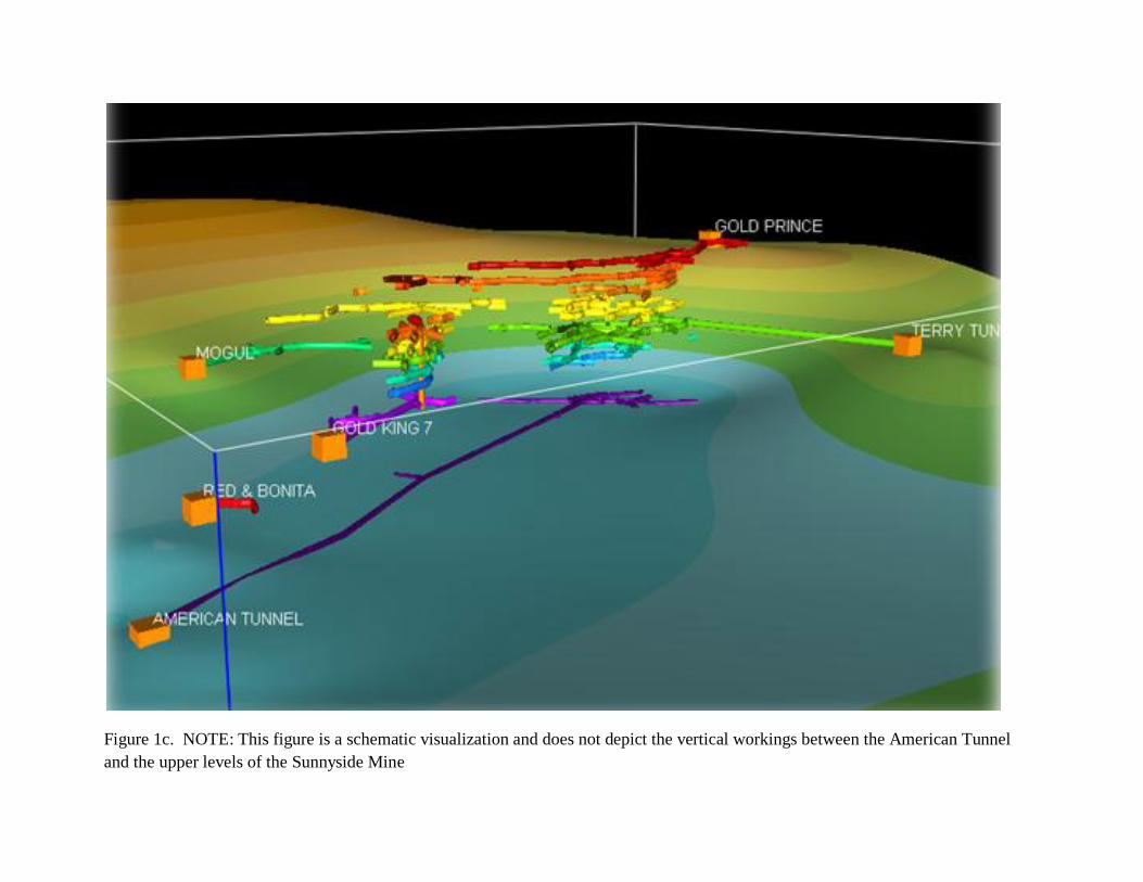
Figure 1c. NOTE: This figure is a schematic visualization and does not depict the vertical workings between the American Tunnel
and the upper levels of the Sunnyside Mine

Figure 2: Flow, pH, and Metals Load in the American Tunnel on October 2-3, 1991 (from
DRMS, 2001)

Figure 3: Schematic Cross Section Illustrating the Completion of the American Tunnel to Serve as Main Access and Haulage Way for
the Sunnyside Mine (Modified from Simon Hydro-Search, 1992)

Figure 4: Schematic of Mine Levels with Bulkhead Locations (Vertical Workings not shown). The Gold Prince and Mogul Bulkheads
are not included in Table 1, and the Terry Tunnel #2 Bulkhead is not shown in this Figure 4.

Figure 5. Modified from Burbank and Luedke, 1969.
1 mile 0
= BULKHEAD (approximate locations)

Figure 6: Red and Bonita Underground Workings Map

Figure 7: Spatial Relation of American Tunnel Bulkhead #2 and Water Producing Fracture Zone with Red and Bonita Mine Workings

Figure 8: Geologic Map Illustrating Mineralized Fissures, Faults, and Veins in the vicinity where the North Fork of Cement Creek
passes over the American Tunnel some 630 feet below. Note North-South and Northeast Trending Structures with Surface Expression
Directly over the Mapped and Potential Projected Red and Bonita Mine Workings. From Burbank and Luedke, 1969.

Figure 9: Simplified Structural Geology Map showing Northeast/Southwest Structure of Eureka Graben, Arcuate Bonita Fault from
the Collapse of the Silverton Caldera, and North/South Fractures that cut the American Tunnel West of the Gold King Mine (from
Simon Hydro-Search, 1992)

Figure 10: Plan View of American Tunnel from Portal to Station 34+00, showing the Location where North Fork of Cement Creek
crosses over the Tunnel. From DRMS, 2001.

Figure 11: Cross Section of the American Tunnel from Portal to Station 31+00. From DRMS, 2001.

Figure 12: Compressive Strength and Density Values for Volcanic Rocks near Red and Bonita
Mine (from DRMS, 1993)

Figure 13: Pressure Load Diagram for Bulkhead Concrete Forms

Figure 14: Location of Red and Bonita Mapped Workings, Adams Mine Workings, and Adit 268-21 Portal

Figure 15: Adams Mine Map

Appendix A
Red and Bonita Bulkhead
Design Calculation Spreadsheets

Appendix B
Red and Bonita Bulkhead
Construction Requirements and Specification

Appendix C
Red and Bonita Bulkhead
2014 Packer Test Results