DESIGN ASPECTS OFA BURIED OIL PIPELINE ON THE …research.iarc.uaf.edu/NICOP/DVD/ICOP 1998...
11
Introduction The Badami oil pipeline is being constructed by BP Exploration Alaska, and will run from Badami to a tie-in with the Endicott pipeline, a distance of about 40 km parallel to the Northern coastline of Alaska. The oil will then be transported to Prudhoe Bay in the existing Endicott line, for transfer to southern markets via the Trans Alaska pipeline. Early design concepts called for a fully buried line, and some of the design issues with such a pipeline are discussed in this paper. Later, much of the pipeline was changed to an elevated mode for reasons of process constraints and oil rheology. However, future projects that consider a buried pipeline option will be confronted with many of the same aspects discussed in the following. The Badami project will transport about 5000 m 3 /day (33,000 bbl/day) of crude oil from the Badami field in a westerly direction to the Endicott pipeline. The route is underlain by thick, continuous cold permafrost, with mean ground temperatures of -10 to -7¡C. The surface 2 to 4 m of soils are ice rich silts and silty sands, under- lain by denser, thaw stable gravels. The surface silts can be extremely ice rich in many areas, and any thawing of in situ soils or re-worked backfill soils would be accom- panied by large settlements. No significant slopes or slope stability issues are present along the route. The route crosses 3 major and several minor rivers. The smaller of the these rivers have only minor deep seasonal thawed zones associated with their active flood planes. The exception to this is the Sag River, which has a significant talik (unfrozen zone) to a depth of 12 m or more in places. As the oil flows down the pipeline, it gains or loses heat to the surrounding environment depending on the thermal properties of the oil and the surrounding soil. The temperature to which the pipeline loses or gains heat in the ground varies throughout the year due to large seasonal temperature fluctuations at the pipeline burial depth. With typical project oil flow rates, the late August temperatures at the outlet point of the pipeline is pre- dicted to be -0.6¡C. The late February profile which is the coldest profile predicted for the analysis, predicts an outlet temperature of -12¡C. Abstract The Badami oil pipeline originally involved a cool buried oil line along its 40 km length. Axial stresses can result from ice wedge cracking. A solution for stresses induced by ice wedge cracking is developed, and results indicate strains are within allowable limits for the pipe section. The backfill over a cool buried pipe will thaw each summer, resulting in potentially high thaw settlements in the surface icy soils. Thaw settlement tests on excavated frozen soil allowed the development of a "Ditch Settlement Index" (DSI). Amounts of granular backfill to balance anticipated trench backfill settlement could then be estimated Concerns for frost heave, and blockage of ground water flow due to chilled pipe operation in an unfrozen river bed were addressed. Frost heave tests indicated that such soils would not be susceptible to significant heave. Further, the convective action of flowing groundwater would cause the frost bulb to seasonally shrink, reducing the impediment to ground water movement. John Greenslade, J.F. (Derick) Nixon 359 DESIGN ASPECTS OF A BURIED OIL PIPELINE ON THE ALASKAN NORTH SLOPE John Greenslade 1 , J.F. (Derick) Nixon 2 1.Colt Engineering Ltd Calgary, Alberta 2. Nixon Geotech Ltd Box 9, Site 9, RR6 Calgary, Alberta T2M 4L5 e-Mail: [email protected]
Transcript of DESIGN ASPECTS OFA BURIED OIL PIPELINE ON THE …research.iarc.uaf.edu/NICOP/DVD/ICOP 1998...

Introduction
The Badami oil pipeline is being constructed by BPExploration Alaska, and will run from Badami to a tie-in with the Endicott pipeline, a distance of about 40km parallel to the Northern coastline of Alaska. The oilwill then be transported to Prudhoe Bay in the existingEndicott line, for transfer to southern markets via theTrans Alaska pipeline. Early design concepts called fora fully buried line, and some of the design issues withsuch a pipeline are discussed in this paper. Later, muchof the pipeline was changed to an elevated mode forreasons of process constraints and oil rheology.However, future projects that consider a buried pipelineoption will be confronted with many of the sameaspects discussed in the following.
The Badami project will transport about 5000 m3/day(33,000 bbl/day) of crude oil from the Badami field in awesterly direction to the Endicott pipeline. The route isunderlain by thick, continuous cold permafrost, withmean ground temperatures of -10 to -7¡C. The surface 2to 4 m of soils are ice rich silts and silty sands, under-lain by denser, thaw stable gravels. The surface silts canbe extremely ice rich in many areas, and any thawing of
in situ soils or re-worked backfill soils would be accom-panied by large settlements. No significant slopes orslope stability issues are present along the route.
The route crosses 3 major and several minor rivers.The smaller of the these rivers have only minor deepseasonal thawed zones associated with their activeflood planes. The exception to this is the Sag River,which has a significant talik (unfrozen zone) to a depthof 12 m or more in places.
As the oil flows down the pipeline, it gains or losesheat to the surrounding environment depending on thethermal properties of the oil and the surrounding soil.The temperature to which the pipeline loses or gainsheat in the ground varies throughout the year due tolarge seasonal temperature fluctuations at the pipelineburial depth.
With typical project oil flow rates, the late Augusttemperatures at the outlet point of the pipeline is pre-dicted to be -0.6¡C. The late February profile which isthe coldest profile predicted for the analysis, predicts anoutlet temperature of -12¡C.
Abstract
The Badami oil pipeline originally involved a cool buried oil line along its 40 km length. Axial stresses canresult from ice wedge cracking. A solution for stresses induced by ice wedge cracking is developed, and resultsindicate strains are within allowable limits for the pipe section.
The backfill over a cool buried pipe will thaw each summer, resulting in potentially high thaw settlements inthe surface icy soils. Thaw settlement tests on excavated frozen soil allowed the development of a "DitchSettlement Index" (DSI). Amounts of granular backfill to balance anticipated trench backfill settlement couldthen be estimated
Concerns for frost heave, and blockage of ground water flow due to chilled pipe operation in an unfrozenriver bed were addressed. Frost heave tests indicated that such soils would not be susceptible to significantheave. Further, the convective action of flowing groundwater would cause the frost bulb to seasonally shrink,reducing the impediment to ground water movement.
John Greenslade, J.F. (Derick) Nixon 359
DESIGN ASPECTS OF A BURIED OIL PIPELINEON THE ALASKAN NORTH SLOPE
John Greenslade1, J.F. (Derick) Nixon2
1.Colt Engineering LtdCalgary, Alberta
2. Nixon Geotech LtdBox 9, Site 9, RR6
Calgary, Alberta T2M 4L5e-Mail: [email protected]

No thawing was anticipated to take place beneath thepipeline under normal operating conditions. Occasionalexcursions of the oil inlet temperature above the soilmelting point (0¡C) could be tolerated during upsetconditions, without undue melting or settlement in theunderlying icy soils.
In summary, the construction and operation of aburied oil pipeline from Badami to Prudhoe appearsfeasible from a geotechnical and geothermal perspec-tive, assuming the crude oil properties allow processingand pumping at colder temperatures. The followingsections illustrate some of the design issues that wereaddressed during the development of the buriedpipeline concept.
Ice wedge cracking
Ice wedge polygons form in permafrost with coldground temperatures due to thermal contraction in thenear surface soils, after a sudden cooling trend. Thecoefficient of thermal expansion ( and contraction) forfrozen soil is quite large, in the range of 50 to 200 x 10-6 ¡C-1 for silts (Mackay, 1975), and as high as400 x 10-6 for clays (Grechishchev, 1972). As a result,large tensile stresses can be induced in the ground nearsurface. If the tensile stresses exceed the tensile strengthof the frozen soil, a narrow crack can open suddenly inthe soil to depths of 2-4 m. Various reports (Mackay,1975 at Garry Island, NWT) indicate that the cracks can
be up to 8 mm wide, but more usually 2 to 5 mm wide(Knight, 1971 at Barrow, Alaska) at the permafrost table0.6 m down. Fukuda (1981) reported average crackwidths of 4 mm at Tuktoyaktuk, NWT. Cracks typicallyopen about once per year, on a polygonal spacing in therange of 20 - 60 m. The crack later fills with waterwhich freezes, and after many years this gives rise tothe well known wedge shaped ice feature, that can beup to 1.0 m or more across at the top of the wedge.
Because the crack occurs quickly, stresses can beapplied to a buried pipe through the tangentialadfreeze bond formed between the pipe and the frozensoil at burial depth (Figure 2). An analysis can be devel-oped to calculate the peak tensile stress induced in theburied pipe, and the resulting stress depends largely onthe adfreeze bond strength developed between the pipeand the frozen ground. Pipe diameter, wall thickness,type of external coating, pipe/soil temperature andbackfill type are other significant factors in the assess-ment of these stresses. Once these parameters are estab-lished by testing and/or literature review, calculationsof the likely magnitude of tensile stresses due to icewedge cracking can be carried out. The effects of icewedge cracking on a buried pipe are not considered tobe cumulative from year to year, due to annual warm-ing in the surface soil layers, and creep relaxation ofinduced shear stresses with time.
The 7th International Permafrost Conference360
Figure 1. Badami pipeline route location.

PIPE - SOIL ADFREEZE STRENGTH
A series of laboratory tests were carried out by ShawPipe Protection in Calgary to measure the shearadfreeze bond strength between frozen sand/graveland a coated pipe at -12¡C. A cylindrical volume ofsand about 11 cm long parallel to the pipe, and about 30 cm diameter was frozen for 1.5 days. A length of 10cm diameter pipe was embedded in the sand prior tofreezing. The pipe was then loaded extremely rapidlycausing failure of the frozen bond between sand andcoating. Peak stress was reached typically in about 2seconds, appropriate for field rates of ice wedge crac-king. Three different coatings were tested, for a total of9 tests.
The YJII coating provided the lowest peak shearstrength, with a range of 483-621 kPa. The FBE coatinggave a somewhat higher range of 580-780 kPa. Finally,the HPCC coating gave a wider range of 435-704 kPa.The average value for each coating varied from 566 to704 kPa. A larger pipeline diameter would tend to giveslightly lower unit adfreeze stresses, according to pile
design theory, so therefore the values for the smallerpipe tested would tend to be conservative (high). Yieldduring the testing took place at the exterior coating-frozen soil contact, and no damage to the pipe-coatingbond was noted.
The above testing indicates that a peak shear stress of690 kPa would be a reasonable value for design. Theinitial slope of the stress-strain curve was not mea-sured, but is less important in the analysis for effects ofice wedge cracking. Initial estimates of the pre-yieldslope of the load-displacement used published valuesfor the dynamic Young's modulus (13.8 x 10⁶ kPa) toestimate the initial modulus.
ANALYSIS FOR ICE WEDGE CRACKING
Analysis for stresses induced in a buried cold ambientpipeline were carried out using a closed form (exact)solution developed here. The Nixon Geotech PIPSOLpipe structural program (Nixon, 1994) has been appliedto the same problem, both to check the closed formsolution, and to provide results for more complex situa-
John Greenslade, J.F. (Derick) Nixon 361
Figure 2. Geometry of buried pipe crossing ice wedge.
tions involving a non-linear pipe, and the effects ofinternal pressure.
The pipe used in all cases was a 0.508 m diameter, 11.1 mm wall, Grade 448 MPa (X-65) steel. The soil isassumed to be frozen sand, which has a peak shearstrength in the range of 690 kPa in contact with thepipe.
The ice wedge crack problem can be simulated byeither (a) applying a displacement to the exposed endof the pipe equal to the crack half-width, as done in theclosed form solution, or (b) applying a displacement tothe end of the axial soil springs attached to the pipe, asdone in the PIPSOL simulations. Either load mechanismapplies the same relative pipe-soil displacement, andshould result in the same stresses and displacements inthe pipe. As illustrated on Figure 2, the problem is sym-metrical about the wedge center-line, and only one halfof the crack width need to be applied to the exposedend of the pipe.
The closed form solution is limited to a linear pipe,and a soil that has an elastic-perfectly plastic shearstress-displacement relationship. The advantage of the
closed form approach is implementation on a spread-sheet, and dozens of cases can be studied in a shorttime.
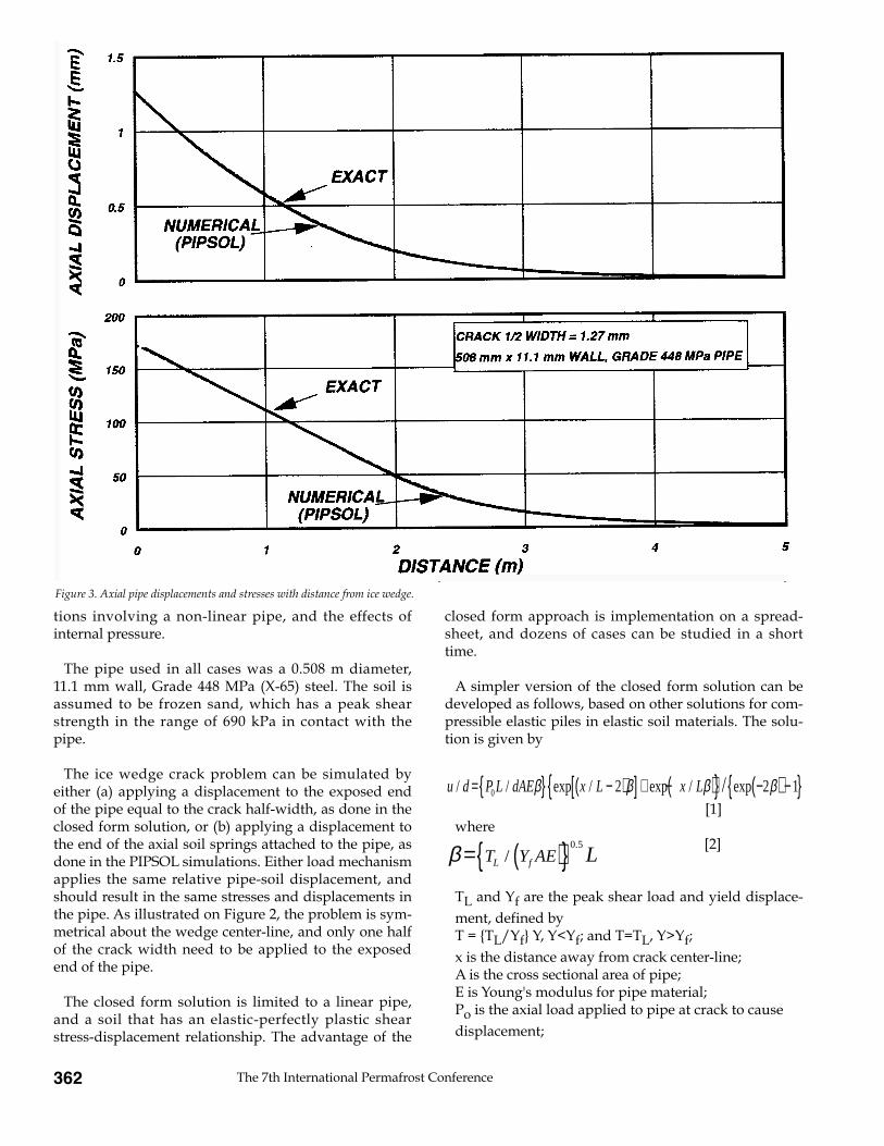
A simpler version of the closed form solution can bedeveloped as follows, based on other solutions for com-pressible elastic piles in elastic soil materials. The solu-tion is given by
[1]where
[2]
TL and Yf are the peak shear load and yield displace-ment, defined by T = {TL/Yf} Y, Y<Yf; and T=TL, Y>Yf;x is the distance away from crack center-line;A is the cross sectional area of pipe;E is Young's modulus for pipe material;Po is the axial load applied to pipe at crack to cause displacement;
The 7th International Permafrost Conference362
Figure 3. Axial pipe displacements and stresses with distance from ice wedge.
u d P L dAE x L x L/ / exp / exp / exp={ } −( )[ ] + −( ){ } −( ) −{ }0 2 2 1β β β β/
β = ( ){ }T Y AEL f L/.0 5

L is the total length of pipe considered (sufficientlylong that ice wedge shear stresses fall to zero alongpipe exterior);and d is the pipe diameter.
This solution can be extended to the more generalcase of an elastic-plastic soil, and a more complex exactsolution can be developed (Murff, 1975). This morecomplex solution has been solved using a spreadsheetsolution.
In order to check the solution against a numerical PIP-SOL simulation, a crack half-width of 2.5 mm wasselected. Due to the symmetry of the problem, onlyone-half of the total crack width needs to be applied asthe relative pipe-soil axial displacement. The compari-son between the closed form and numerical PIPSOLresults for axial pipe stresses and displacements areshown on Figure 3. The agreement is very good, indi-cating the accuracy of both approaches, at least for alinear pipe. The solution also indicates that the relativedisplacements between the pipe and soil dissipate overa relatively short distance from the ice wedge cracklocation. Within about 3 m of the crack, the pipe hasadapted to the new free field axial displacements. Thepeak axial pipe stress for this case is about 170 MPa, orabout one third of the pipe yield stress.
The PIPSOL program was then used for a series ofcases to try to establish the important variables affec-ting pipe strains. Figure 4 shows the effect of internalpipe pressure on the peak axial strain developed at acrack. The crack half-width was varied from 0 to 5 mm.The case with internal pressure provides the greaterpipe strains at the crack location, as internal pressureresults in an initial tensile stress in the axial directiondue to the Poisson effect. Clearly, using a zero tempera-ture differential (difference between pipe operatingtemperature and pipe backfilling temperature) will pro-vide the worst case. For a total crack width of around 10 mm, the peak axial strain in the pipe for this basecase is about 0.2%. The corresponding axial stresses aregiven on Figure 5. For crack half-widths above about2.5 mm, the pipe will be strained inelastically, and theaxial tensile stresses will exceed the limit of proportionality.
Higher peak shear strength results in higher strains inthe pipe. The peak tensile strain appears to be relatedapproximately to the square root of the peak shearstress at the pipe-soil contact. Finally, the yield displace-ment in the soil load-displacement function appears tohave little effect on the peak axial tensile strain in thepipe, provided that the applied crack width is greaterthan the yield displacement.
John Greenslade, J.F. (Derick) Nixon 363
Figure 4. Effects of internal pressure and crack width on axial strains.

Ditch backfill and settlement
Replacement of native, icy soils in the pipeline trenchwould result in a significant settlement trough develo-ping along the top of the buried pipe. Although thiscould be offset by periodic maintenance in the first fewyears after construction, these effects can be limitedfrom the outset. This can be done by partial replace-ment of the native backfill in the trench by thaw stablebackfill. Mounding of the remaining icy trench spoilover top of the trench will limit the amount of settle-ment immediately over the ditchline, yet preserves thenatural insulating qualities of the fine-grained andorganic soils on the ground surface. This would assistin maintaining cooler ground surface temperatures,limit water flow into the ditch, and help in re-vegetation.
In order to estimate the quantity of thaw stable, gran-ular fill along the pipeline, a new test was devised toprovide input on the anticipated amount of settlementin the ditch backfill. At the time, it was planned to exca-vate the pipeline trench with a wheeled ditcher duringthe winter, producing a relatively homogeneous mix-ture of frozen chips of soil and ice. Following replace-
ment and subsequent thaw over the pipeline, thefrozen, unsaturated backfill mixture would thaw, settleand saturate over time. The net settlement from thefrozen, porous condition to the final thawed and con-solidated saturated condition could not be estimatedfrom any existing thaw strain correlations for naturalsoils.
A total of 47 samples were collected during auguringof the frozen soils in the top 1.5 m of the soil profile inthe spring 1995 geotechnical field program. Each bulk,augured sample was sufficient to fill a 20 liter plasticpail, and this was shipped to Prudhoe Bay for testing.The samples were tamped gently in the frozen condi-tion, and then allowed to thaw in an uncontrolled man-ner in a warm building. After completion of thaw, theoverall thaw strain was denoted as "DSI", or ditch set-tlement index.
Figure 6 shows the distribution of the results with dis-tance along the pipeline route. No particular trend withdistance was noted. The average for all tests was 56%,with a standard deviation of 12.9%. No strong correla-tion with geological landform was observed, althoughfluvial deposits tended to strain less (50%) than surfacedeposits (56%), or icy thaw lake deposits (62%). These
The 7th International Permafrost Conference364
Figure 5. Effect of peak shear stress on maximum axial tensile strain.

values were then used to calculate the volume thatwould be required to make up the volume loss associa-ted with thawing of the ditch backfill in the trench, andmounded up over the trench. As shown simplisticallyon Figure 7, some assumption must be made about theside slopes and shape of the backfill mound, so that thecorrect amount of granular fill can be placed in theditch over the pipe. Typically, about 0.6 - 0.7 m of gran-ular fill was required in the trench over the pipe. In thefirst year or so after construction, some re-working andrestoration of the backfill mound would be requiredalong much of the routing, as it is not possible toreplace all the backfill mound directly over the excava-ted trench.
The use of select coarse-grained backfill in the lowerpart of the pipe trench will reduce the amount of thawsettlement in the trench backfill, and help control theformation of a surface trough along the top of the pipe.However, the presence of coarse, permeable sand back-fill around the pipe might also result in an increasedpotential for subsurface ground water flow along thepipe trench. Low permeability ditch plugs were to beused to limit ground water flow in the trench parallel tothe pipeline, in order to limit additional heat input tothe soils around the pipe from flowing groundwater.
Granular backfill over the pipe would also assist in limiting the possibility of upheaval buckling at lowangle overbends (see Nixon and Burgess, 1998).
Frost heave at Sag River crossing
The potential for frost heave beneath the buriedBadami chilled oil pipeline was assessed. Some of thegravels beneath the active channel at the Sag River arethawed, and a bulb of frozen soil will therefore formaround the pipe beneath the river bed. These gravelsare clean, and relatively deficient in fine sized soil parti-cles, and are therefore not expected to exhibit signifi-cant frost susceptibility.
Samples were collected by D. Miller and Associates ofAnchorage and tested in Calgary. In addition, watercontents, grain size and laboratory permeability testswere carried out on the 2 bulk samples, in order to clas-sify and further determine properties of the actual sam-ples tested.
The lab frost heave test was carried in a 10 cm diame-ter cell maintained by the first author. Unique featuresof the cell include a constant temperature (-1¡C) circu-lating jacket around the cell, that allows tests to be car-
John Greenslade, J.F. (Derick) Nixon 365
Figure 6. DSI (Ditch Settlement Index) with distance along route.

ried out in a warm room. Based on the Konrad-Morgenstern (1983) frost heave approach, the rate ofheave can be calculated from 1.09 times the SP parame-ter multiplied by the temperature gradient at the free-zing front. Using this definition, the SP (SegregationPotential) parameter can be extracted (Figure 8). The SPvalues are very low, in the range of 0.1 to 5 mm2/day.¡C, when compared with typical values forsilts and clays, which are in the range of 80-250 mm2/day.¡C. This indicates the low frost sus-ceptibility of these materials.
The percentage fines (#200 sieve) is 1.5% and 1.9% forSamples 1 and 2. These values are entirely consistentwith the low frost susceptibility confirmed for the frostheave tests samples. Saturated water contents of 12-13%by dry weight were observed for the samples at the endof the tests. Permeability tests gave an average per-meability of 2.2 x 10⁻² cm/sec after correction to fieldtemperatures.
Based on pipe structural analysis, the allowable frostheave for the Badami pipeline is about 0.3 m for anappropriate combination of loadings. Frost heave pre-dictions based on the heave test results and geothermalpredictions for frost bulb growth (Figure 10), wouldgive rise to a pipe heave of 0.025 m or less. In view ofthe very small anticipated frost heave in relation to theallowable value, there was no indication that pipe dis-placements resulting from frost heave at the Sag River(or other crossings on this project) would pose anydesign concern for the pipeline.
Interruption to groundwater flow
A concern for subsurface blockage of ground waterflow existed at the Sag River crossing, due to the pres-ence of a significant thawed zone, (talik) within thezone of soil freezing beneath the pipe. If significantground water flow occurred particularly through thewinter, there is a potential for icings in the region of theburied pipe crossing. In order to more correctly predictthese effects, and their possible impacts on ground
The 7th International Permafrost Conference366
Figure 7. Anticipated settlement and restoration of trench backfill.

water flow and frost bulb growth, a more detailed andcomplex geothermal analysis of the crossing was made.If significant ground water velocities are present (i.e.greater than about 3x10⁻⁵ cm/sec), then the size of thefrost bulb will be reduced, as will the potential forblockage of ground water flow.
The Nixon Geotech THERM2 model with a convectiveground water flow option was used to predict thegrowth of the frost bulb around the buried pipe (Nixon,1983). As outlined above, the average permeability ofthe fine gravel samples obtained from the Sag river bedwas about 2.2 x 10⁻² cm/sec. The river bed gradients inthis area were estimated to be in the range of 0.005 orso. The product of these two numbers provides an esti-mated, typical initial ground water flow velocity ofaround 1x10⁻⁴ cm/sec. This is in the range of flowvelocities where convective heat transfer effects becomesignificant.
Figure 9 shows the predicted shape of the frost bulb inlate summer and winter, with no convective effects of
flowing ground water. The figure also shows the frostbulbs for the same times, with the effects of convectiveheat flow incorporated. The frost bulb is changed less inlate winter, but shrinks to almost nothing in late sum-mer. This is partly due to the warmer pipe temperaturesat this time of the year. Finally, Figure 10 shows the sea-sonal effects of frost bulb growth above and below thepipe. The frost bulb for the case with convectionappears to have reached equilibrium after 2-3 years,extending about 1.5 m below pipe base.
Therefore, in areas where a large unfrozen zone exists,the size of the frost bulb should be limited by the flo-wing groundwater itself. In areas where ground waterflows are low or zero, then the frost bulb will be larger.On the other hand, concerns for ground water relatedissues such as icing formation and blockage of subsur-face flow will be lower for these cases of lower groundwater flow.
John Greenslade, J.F. (Derick) Nixon 367
Figure 8. Segregation potential vs stress for sag river samples # 1 & 2.

The 7th International Permafrost Conference368
Figure 9. Maximum and minimum size of frost bulb for grounwater velocity = 0. 1 X 10⁻⁴ cm/sec.
Figure 10. Frost depth above and below pipe in artic river.

Acknowledgments
The authors thank BPXA in Anchorage for permissionto publish this study. Extensive assistance of many col-leagues at BPXA and Colt Engineering in Calgary is sin-cerely appreciated. Shaw Pipe in Calgary carried outthe pipe soil interface shear strength tests. Intellectualsupport and field data by Duane Miller and Associatesin Anchorage proved invaluable, in particular duringdevelopment of the DSI parameter.
John Greenslade, J.F. (Derick) Nixon 369
References
Fukuda, M. (1981). Field observations of ice wedge crackingin the permafrost area near Tuktoyuktuk, NWT, Canada.Joint studies on Physical and Biological Environments.Reprint from Institute of Low Temperature Science,Hokkaido University, Japan.
Grechishchev, S. (1972). Basic laws of thermorheology andtemperature cracking of frozen ground. Proceedings of the2nd International Permafrost Conference, USSRContribution. pp. 228-233.
Knight, G. (1971). Ice wedge cracking and related effects onburied pipelines in permafrost. In Burdick, J. (ed.),Proceedings of a Symposium on Cold RegionsEngineering, University of Alaska College, pp. 384-395.
Konrad, J-M and Morgenstern, N. (1983). SegregationPotential. Proceedings of the 4th International PermafrostConference, Fairbanks, Alaska. Washington, D.C.,National Academy of Sciences, pp. 660-665.
Mackay, J. (1975). The closing of ice wedge cracks in per-mafrost, Garry Island. Canadian Journal of Earth Sciences, 12,1668-1674.
Miller, D. and Associates (1994). Geotechnical Investigation:Badami soils investigation, North Slope, Alaska. Draft,Nov 3. Report to BP Exploration (Alaska) Inc.
Murff, J. (1975). Response of axially loaded piles. ASCEJournal of Geotechnical Engineering 101, GT3, 356-359.
Nixon, J. (1983). Practical applications of a versatile geother-mal simulator. Transactions ASME-JERT, 105, 442-447.
Nixon, J. (1994). Role of heave pressure dependency and soilcreep in stress analysis for pipeline frost heave. InProceedings, 7th International Cold Regions SpecialtyConference, Edmonton. pp.397-412.
Nixon, J. and Burgess, M. (1998). Norman Wells pipeline set-tlement and uplift movements. Canadian GeotechnicalJournal (in press).