Design Architecture of Attitude Determination and Control...
23
Design Architecture of Attitude Determination and Control System of ICUBE 9th Annual Spring CubeSat Developers' Workshop, USA Author : Naqvi Najam Abbas Co-Author: Dr. Li YanJun Affiliation: Space Academy, Department of Astronautics Northwestern Polytechnical University Xi’an, CHINA
-
Upload
doankhuong -
Category
Documents
-
view
223 -
download
1
Transcript of Design Architecture of Attitude Determination and Control...

Design Architecture of Attitude
Determination and Control System of ICUBE
9th Annual Spring CubeSat Developers'
Workshop, USA
Author : Naqvi Najam Abbas
Co-Author: Dr. Li YanJun
Affiliation: Space Academy, Department of Astronautics
Northwestern Polytechnical University
Xi’an, CHINA

Personal Profile
• Author: Naqvi Najam Abbas ([email protected])
• Qualifications: PhD Scholar ( 2009-To date, NPU, China)
Specialized MS in GNSS and Related Applications, Italy
MS Electrical Engineering, NUST,PK
BS Electrical Engineering, UET, PK
• Professional Experience: Research Assistant NPU, China
Assistant Professor, IST, PK
Scope
ADCS Flow Diagram
Attitude Sensors and Representation
Design Architecture
Attitude Determination (AD)
Orbit Design – AD – AC SIMULATION
IST- CUBESAT- ICUBE
AD Algorithms –Actuators - Disturbances
Conclusion - Recommendations - References

Institute of Space Technology, Islamabad, Pakistan
• Institute of Space Technology (IST)[1], Islamabad, Pakistan is a Public sector University offering BS and MS degrees in Aerospace, Electrical and Materials Engineering
• IST initiated the CUBESAT project in 2009 with the aim to train its undergraduate and graduate students for the satellite technology and to develop and acquire the hands-on experience for the development, integration and launch of CubeSat.
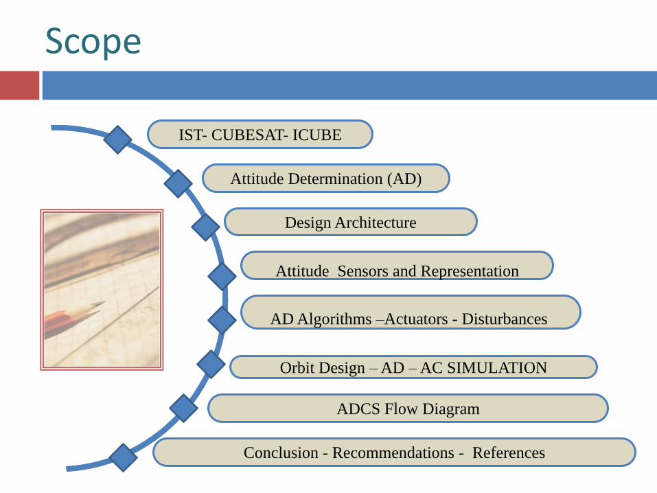
CUBESAT- ICUBE-1
• ICUBE-1 is the first experimental CUBESAT of this series that is planned to be launched in 2013 in LEO orbit at the height of 650 KM with an inclination of 98.8 degrees in the Sun synchronous orbit for a period of one and a half year.
• The 1U CubeSat structure of dimension 10cm cube with a maximum mass of 1 kg is used for the ICUBE-1.
• An imaging payload consisting of a small, low resolution CMOS camera will be used for capturing photographs.
• Commercial off-the Shelf (COTS) components and modules already flown in space will be used for this first satellite. The detailed subsystem overview and system engineering analysis is given at [2].

ATTITUDE DETERMINATION
The Attitude of a spacecraft is its orientation in space with respect to a given coordinate system. Attitude determination and control system (ADCS) involves defining of coordinate system, selecting attitude representation parameters, designing orbit propagator, selection of attitude determination sensors and algorithms, mathematical modeling of kinematics, dynamics, disturbance torques and sensors, and finally the selection of control schemes and actuators along with the appropriate control and stabilization schemes[3].

Attitude Determination Overview
Control Law
Desired Attitude
Real Time
Attitude
Determination
Real Time Attitude
Estimation
None (Passive)
Linear
Limit Cycle
Non-Linear
Deterministic
Filters
Spacecraft Computer
Attitude
Actuators
Control Commands
Spacecraft
Dynamics
Internal
Disturbance
Torques
External
Disturbance
Torques
Attitude
Sensors
Definitive
Attitude
Determination
Solar Arrays
Flexible Components
Rotating Mechanisms
Fuel Slosh
People
Aerodynamics
Magnetic
Gravity Gradient
Solar Radiation
Thrusters
Magnetic Torque Rod
Momentum and
Reaction wheel
Movable Components
Attitude
Measurement Filter
Bias Determination
Earth, Sun, Stars
Magnetometer
Gyroscopes
Payload Sensors

DESIGN ARCHITECTURE
Mission: Student Satellite
Size : NanoSatellite - 1U-10 cm cube
Mass : Less than 1Kg
Orbit : LEO Sun Synchronous Orbit
Height: 650 km
Sensor : Magnetometer
Actuator : Magneto-Torquer rods / Coils
Mission Endurance: 12 -18 Months
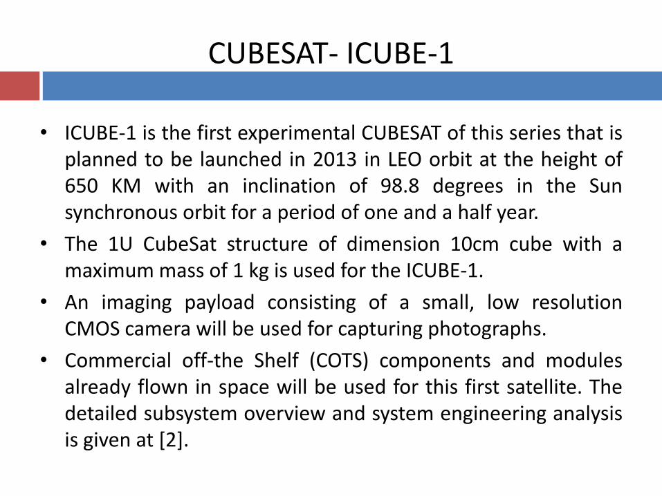
AD SENSORS CHOICE
Sensor Accuracy
(Degrees) Pros Cons
Sun Sensor 0.1 Reliable, Simple, Cheap No measurement in
eclipse
Horizon
Scanner 0.03 Expensive
Orbit dependent,
Poor in yaw
Magnetometer 1 Cheap– Continuous Coverage Low Altitude only
Star Tracker 0.001 Very Accurate Expensive-Heavy-
Complex
Gyroscope 0.01 per hour High Band Width Expensive-Drifts
with time

AD REPRESENTATION PARAMETER CHOICE
Representation Par. Characteristics Applications
Rotation matrix
(Direction cosine
matrix)
9
Inherently Nonsingular
Intuitive Representation
Difficult to maintain orthogonality
Expensive to store
Six redundant Parameters
Analytical studies and transformation
of vectors
Euler angles
3
Minimal set
Clear physical interpretation.
Trigonometric functions in rotation matrix and kinematic
relation
No convenient product rule
Singular for certain rotations
Theoretical physics,
Spinning Spacecraft
Attitude Maneuvers.
Used in analytical studies.
Axis-azimuth
3
Minimal set
Clear physical interpretation.
Often computed directly from observations.
No convenient product rule.
Computation of rotation matrix difficult.
Singular for certain rotations.
Trigonometric functions in kinematic relation.
Primarily Spinning Spacecraft.
Rodriguez
(Gibbs vector)
3
Minimal set
Singular for rotations near θ = ± π.
Simple kinematic relation
Analytic Studies.
Quaternions (Euler
symmetric parameters
4
Easy orthogonality of rotation matrix.
Not singular at any rotation.
Linear simple kinematic equations.
No clear physical interpretation.
One redundant parameter.
Preferred Attitude representation
for attitude control systems
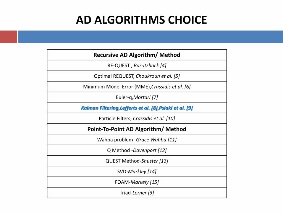
AD ALGORITHMS CHOICE
Recursive AD Algorithm/ Method
RE-QUEST , Bar-Itzhack [4]
Optimal REQUEST, Choukroun et al. [5]
Minimum Model Error (MME),Crassidis et al. [6]
Euler-q,Mortari [7]
Kalman Filtering,Lefferts et al. [8],Psiaki et al. [9]
Particle Filters, Crassidis et al. [10]
Point-To-Point AD Algorithm/ Method
Wahba problem -Grace Wahba [11]
Q Method -Davenport [12]
QUEST Method-Shuster [13]
SVD-Markley [14]
FOAM-Markely [15]
Triad-Lerner [3]

DISTURBANCE TORQUES IMPLEMENTED
Type/Sources of Torques Remarks
Gravity-Gradient Varies inversely with distance from the Earth
Centre
Solar Radiation Pressure Effects geostationary spacecrafts
Earth’s Magnetic Field Used for passive Attitude Control of small
spacecrafts
Aerodynamic Forces Effective for altitudes up to 800 km (LEO)
Flexible Structures Effective for big flexible structures
Internal Magnetic Torques Due to residual permanent magnetism, Closed
loop currents in instrumentation and eddy
currents.
Earth's albedo - reflected
radiations - micrometeorite
impacts -cosmic dust
Less significant sources of torques for small
LEO missions
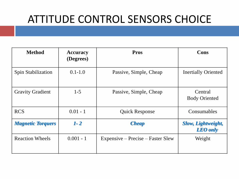
ATTITUDE CONTROL SENSORS CHOICE
Method Accuracy
(Degrees)
Pros Cons
Spin Stabilization 0.1-1.0 Passive, Simple, Cheap Inertially Oriented
Gravity Gradient 1-5 Passive, Simple, Cheap Central
Body Oriented
RCS 0.01 - 1 Quick Response Consumables
Magnetic Torquers 1- 2 Cheap Slow, Lightweight,
LEO only
Reaction Wheels 0.001 - 1 Expensive – Precise – Faster Slew Weight

Orbit Design and Propagator
0 50 100 150 200 250 300 350 400 450 5000
50
100
150
200
250
300
350
400
Time (sec)
Angl
e(de
g)
Mean anomaly
RAAN
Inclination
Arg of perigee
MATLAB – STK Comparison ( Keplarians-Position-Velocity)
0 50 100 150 200 250 300 350 400-8000
-6000
-4000
-2000
0
2000
4000
6000
8000
Time(sec)
Posi
tion(
km)
Position vector in ECI frame
x (km)
y (km)
z (km)
0 50 100 150 200 250 300 350 400-8
-6
-4
-2
0
2
4
6
8
Time(sec)
Vel
ocity
(km
/s)
Velocity vector in ECI frame
x (km/s)
y (km/s)
z (km/s)

ICUBE-1 SIMULINK MODEL

AD SIMULATION Extended Kalman Filter

ATTITUDE CONROL SCHEME Simulink Model
Roll and Yaw control using PD Controller
Pitch control using PD Controller
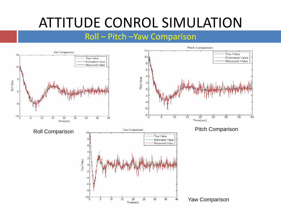
ATTITUDE CONROL SIMULATION Roll – Pitch –Yaw Comparison
Roll Comparison
Yaw Comparison
Pitch Comparison
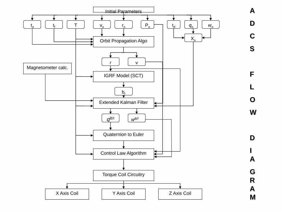
Initial Parameters
to T tf vo ro Po td qo wo
Xo Orbit Propagation Algo
r v
IGRF Model (SCT)
br
Extended Kalman Filter
Magnetometer calc.
qB/I wB/I
Quaternion to Euler
Control Law Algorithm
Torque Coil Circuitry
X Axis Coil Y Axis Coil
Z Axis Coil
A
D
C
S
F
L
O
W
D
I
A
G
R
A
M
CONCLUSION AND RECOMMENDATIONS
• ADCS of ICUBE-1 is designed and simulated
• Magnetometer is used as sensor and Magnetic coils are used as actuators
• EKF is used as Attitude Determination algorithm while PD Controller is used for Attitude Control
• ADCS along with Orbit propagator is simulated in MATLAB/Simulink
• This ADCS Design Architecture is one option for ICUBE-1, other options are also under research and most feasible one will be used for the final design

References
[1] www.ist.edu.pk
[2] Rehan Mahmood, Khurram Khurshid, Qamar ul Islam, “Institute of Space Technology CubeSat: ICUBE-1 Subsystem Analysis and
Design”, 32nd IEEE Aerospace Conference, USA , 2011.
[3] Wertz, J.R., ed., “Spacecraft Attitude Determination and Control,” D. Reidel Publishing Company, Library in Astrophysics and
Space Sciences, 1978.
[4] Bar-Itzhack, I.Y., "REQUEST- A Recursive QUEST Algorithm for Sequential Attitude Determination," J. Guidance, Control,
and Dynamics, vol. 19, No. 5, pp. 1034-1038, Sept.- Oct., 1996.
[5] D. Choukroun, I. Y. Bar-Itzhack and Y. Oshman, “Optimal- REQUEST Algorithm for Attitude Determination,” Journal ofGuidance,
Control, And Dynamics, Vol. 27, No. 3, May–June 2004.
[6] Crassidis, J. L., & Markley, F. L., “Minimum Model Error Approach for Attitude Estimation,” Journal of Guidance, Control, and
Dynamics, vol. 20, No.6, 1241-1247, 1997.
[7] Mortari, D. “Euler-q Algorithm for Attitude Determination from Vector Observations,” Journal of Guidance, Control, and
Dynamics, vol. 21, pp. 328-334, 1998.
[8] Lefferts, Markley and Shuster, “Kalman Filtering For Spacecraft Attitude Estimation,” AIAA, 20th Aerospace Science Meeting,
Orlando Florida, January, 11 -14, 1982.

References
[9] Martel F., Pal P. K. and Psiaki M. L., "Three- Axis Attitude Determination via Kalman Filtering of Magnetometer Data,"
Journal of Guidance, Control and Dynamics, vol. 13, No. 3, pp.506-514, 1989.
[10] Crassidis, Markley and Cheng, “Survey of Nonlinear Attitude Estimation Methods,” Journal of Guidance, Control and Dynamics, Vol
30,No.1,2007
[11] Wahba, G., "A Least Squares Estimate of Spacecraft Attitude, "SUM Review, vol. 7, No. 3, p. 409. July 1965.
[12] Davenport, P., "A Vector Approach to the Algebra of Rotations with Applications,"NASA Technical Note TN D-4696, August 968.
[13] Shuster, M.D. and Oh, S.D., "Three-Axis Attitude Determination from Vector Observations." J. of Guidance and Control, vol. 4, No. 1,
pp. 70-77. Jan.-Feb. 1981.
[14] Markley, F. L., "Attitude Determination Using Vector Observations and Singular Value Decomposition", Journal of the Astronautical
Sciences, No. 36, pp. 245-258, July-Sep. 1988.
[15] Markley, F. L., "Attitude Determination Using Vector Observations: A Fast Optimal Matrix Algorithm,” Journal of the Astronautical
Sciences, vol. 41, No. 2, pp. 261-280, 1993

Thank You


![CDMD CubeSat Deformable Mirror Demonstration (CDMD)mstl.atl.calpoly.edu/~bklofas/Presentations/DevelopersWorkshop2013/... · [7] Bifano, et al. “Microelectromechanical Deformable](https://static.fdocuments.in/doc/165x107/5b91d10809d3f274268c8b88/cdmd-cubesat-deformable-mirror-demonstration-cdmdmstlatl-bklofaspresentationsdevelopersworkshop2013.jpg)