DESIGN AND SIMULATION OF DC-DC CONVERTER WITH HIGH … · dc-dc converter with high voltage gain...
10
http://www.iaeme.com/IJMET/index.asp 565 [email protected] International Journal of Mechanical Engineering and Technology (IJMET) Volume 8, Issue 8, August 2017, pp. 565–574, Article ID: IJMET_08_08_062 Available online at http://www.iaeme.com/IJMET/issues.asp?JType=IJMET&VType=8&IType=8 ISSN Print: 0976-6340 and ISSN Online: 0976-6359 © IAEME Publication Scopus Indexed DESIGN AND SIMULATION OF DC-DC CONVERTER WITH HIGH VOLTAGE GAIN FOR FUEL CELL BASED VEHICLES J S V Siva Kumar and P Venkata sateesh Department of Electrical and Electronics Engineering, GMR Institute of Technology Rajam, AP. India. ABSTRACT The cost of petroleum based fuels are increasing because of its usage.so there is a need to alternate these fuels. Fuel cell vehicles are best solution for this. A single fuel cell gives a voltage nearly 1 to 1.5V. For getting more DC voltage we are connecting the fuel cells are in series. After that the dc voltage can be boosted to high voltage by using boost converter. In this paper we are concentrating on simulation of fuel cell and dc to dc boost converter. By using this converter we are getting a dc output voltage of 500V. This is more than enough to run an electrical vehicle. The simulation results of fuel cell and boost converter are verified in PSIM 9.0.4 software. Keywords: fuel cell, high gain, voltage doubler, current fed, high frequency transformer, boost inductor and leakage inductance. Cite this Article: J S V Siva Kumar and P Venkata sateesh, design and simulation of dc-dc converter with high voltage gain for fuel cell based vehicles, International Journal of Mechanical Engineering and Technology 8(8), 2017,pp. 565–574. http://www.iaeme.com/IJMET/issues.asp?JType=IJMET&VType=8&IType=8 1. INTRODUCTION In the recent years, the energy consumption from the renewable energy sources increases when compared with the conventional energy sources in order to reduce the greenhouse gases which causes global warming, acid rains, air, water, soil pollutions and ozone layer depletion. According world environmental summit reports the conventional energy sources mainly fossil fuels are may be completely vanished by the year 2050. So we have to reserve these conventional energy sources for the next generation and give more importance to the renewable energy sources to replace their applications. The renewable energy sources are mainly solar energy system, wind energy system, biogas energy, geothermal energy, tidal energy, fuel energy system and others. Among which fuel cell technology is the best suitable for stationary and on board automobile applications because of more efficiency, reliable and less weight. Architecture of an electrical vehicle powered with fuel cell shown in Figure 1. The output voltage of single cell is very low which is not enough to run the electric motor
Transcript of DESIGN AND SIMULATION OF DC-DC CONVERTER WITH HIGH … · dc-dc converter with high voltage gain...

http://www.iaeme.com/IJMET/index.asp 565 [email protected]
International Journal of Mechanical Engineering and Technology (IJMET) Volume 8, Issue 8, August 2017, pp. 565–574, Article ID: IJMET_08_08_062
Available online at http://www.iaeme.com/IJMET/issues.asp?JType=IJMET&VType=8&IType=8
ISSN Print: 0976-6340 and ISSN Online: 0976-6359
© IAEME Publication Scopus Indexed
DESIGN AND SIMULATION OF DC-DC
CONVERTER WITH HIGH VOLTAGE GAIN
FOR FUEL CELL BASED VEHICLES
J S V Siva Kumar and P Venkata sateesh
Department of Electrical and Electronics Engineering,
GMR Institute of Technology Rajam, AP. India.
ABSTRACT
The cost of petroleum based fuels are increasing because of its usage.so there is a
need to alternate these fuels. Fuel cell vehicles are best solution for this. A single fuel
cell gives a voltage nearly 1 to 1.5V. For getting more DC voltage we are connecting
the fuel cells are in series. After that the dc voltage can be boosted to high voltage by
using boost converter. In this paper we are concentrating on simulation of fuel cell
and dc to dc boost converter. By using this converter we are getting a dc output
voltage of 500V. This is more than enough to run an electrical vehicle. The simulation
results of fuel cell and boost converter are verified in PSIM 9.0.4 software.
Keywords: fuel cell, high gain, voltage doubler, current fed, high frequency
transformer, boost inductor and leakage inductance.
Cite this Article: J S V Siva Kumar and P Venkata sateesh, design and simulation of
dc-dc converter with high voltage gain for fuel cell based vehicles, International
Journal of Mechanical Engineering and Technology 8(8), 2017,pp. 565–574.
http://www.iaeme.com/IJMET/issues.asp?JType=IJMET&VType=8&IType=8
1. INTRODUCTION
In the recent years, the energy consumption from the renewable energy sources increases
when compared with the conventional energy sources in order to reduce the greenhouse gases
which causes global warming, acid rains, air, water, soil pollutions and ozone layer depletion.
According world environmental summit reports the conventional energy sources mainly fossil
fuels are may be completely vanished by the year 2050. So we have to reserve these
conventional energy sources for the next generation and give more importance to the
renewable energy sources to replace their applications. The renewable energy sources are
mainly solar energy system, wind energy system, biogas energy, geothermal energy, tidal
energy, fuel energy system and others. Among which fuel cell technology is the best suitable
for stationary and on board automobile applications because of more efficiency, reliable and
less weight. Architecture of an electrical vehicle powered with fuel cell shown in Figure 1.
The output voltage of single cell is very low which is not enough to run the electric motor
Design and simulation of dc-dc converter with high voltage gain for fuel cell based vehicles
http://www.iaeme.com/IJMET/index.asp 566 [email protected]
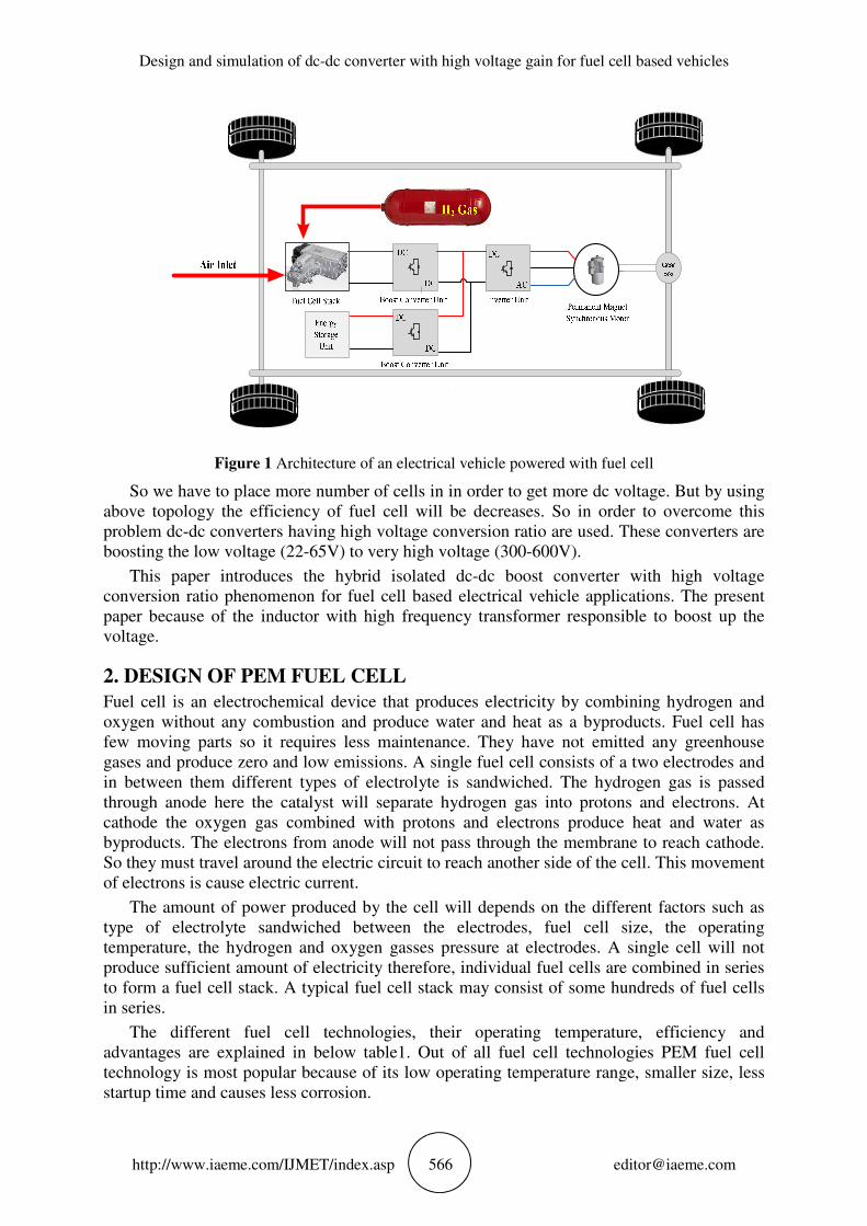
Figure 1 Architecture of an electrical vehicle powered with fuel cell
So we have to place more number of cells in in order to get more dc voltage. But by using
above topology the efficiency of fuel cell will be decreases. So in order to overcome this
problem dc-dc converters having high voltage conversion ratio are used. These converters are
boosting the low voltage (22-65V) to very high voltage (300-600V).
This paper introduces the hybrid isolated dc-dc boost converter with high voltage
conversion ratio phenomenon for fuel cell based electrical vehicle applications. The present
paper because of the inductor with high frequency transformer responsible to boost up the
voltage.
2. DESIGN OF PEM FUEL CELL
Fuel cell is an electrochemical device that produces electricity by combining hydrogen and
oxygen without any combustion and produce water and heat as a byproducts. Fuel cell has
few moving parts so it requires less maintenance. They have not emitted any greenhouse
gases and produce zero and low emissions. A single fuel cell consists of a two electrodes and
in between them different types of electrolyte is sandwiched. The hydrogen gas is passed
through anode here the catalyst will separate hydrogen gas into protons and electrons. At
cathode the oxygen gas combined with protons and electrons produce heat and water as
byproducts. The electrons from anode will not pass through the membrane to reach cathode.
So they must travel around the electric circuit to reach another side of the cell. This movement
of electrons is cause electric current.
The amount of power produced by the cell will depends on the different factors such as
type of electrolyte sandwiched between the electrodes, fuel cell size, the operating
temperature, the hydrogen and oxygen gasses pressure at electrodes. A single cell will not
produce sufficient amount of electricity therefore, individual fuel cells are combined in series
to form a fuel cell stack. A typical fuel cell stack may consist of some hundreds of fuel cells
in series.
The different fuel cell technologies, their operating temperature, efficiency and
advantages are explained in below table1. Out of all fuel cell technologies PEM fuel cell
technology is most popular because of its low operating temperature range, smaller size, less
startup time and causes less corrosion.

J S V Siva Kumar and P Venkata sateesh
http://www.iaeme.com/IJMET/index.asp 567 [email protected]
Fuel cell type Type of electrolyte used Operating temperature
(0C)
System output
range efficiency
Polymer electrolyte
membrane (PEM)
Solid polymer poly
perfluorosulfonic acid 60-140
0C <1KW-250KW 54-59%
Alkaline(AFC)
40% of aqueous
potassium
hydroxide(KOH)
80-110 0C 10KW-100KW 59%
Phosphoric acid (PAFC) Liquid Phosphoric acid 160-190 0C
50KW-1MW >45%
Molten carbonate(MCFC)
Liquid solution of
lithium, sodium&
potassium carbonates
620-670 0C <1KW-1MW 45%
Table 1 different type of fuel cell technologies
The reactions of Polymer electrolyte membrane fuel cells (PEM) takes place at anode and
cathode are shown in be figure 2.
The output voltage of the fuel cell stack is given by the mathematical equation
2 2
2
0 0
.V N [ (ln )] ln(H I ) R
2
H O
FC FC ele FC
H O
P PRTE G I
F P= + − × −
(1)
The partial pressure of the hydrogen gas can be expressed as
2 2 2(P ) (q q 2 )in out
H H H r Fc
an
d RTK I
dt V= − −
(2)
By applying Laplace transform to the above equation we get
2
2
2
2
1( 2k I )
1
in
H r FC
H
H
H
qK
PSτ
−
=+
(3)
2
2
2
2
1( k I )
1
in
O r FC
O
O
O
qK
PSτ
−
=+
(4)
Figure 2 reactions take place at electrodes of PEM fuel cell

Design and simulation of dc-dc converter with high voltage gain for fuel cell based vehicles
http://www.iaeme.com/IJMET/index.asp 568 [email protected]
2
2
2
1(2 k I )
1
r FC
H O
H O
H O
KP
Sτ=
+ (5)
The fuel cell voltage is calculated as
cell act ohmicV E E E= + + (6)
The Nernst’s voltage equation is given as
2 2
2
0 0[ ln( )]2
H o
H O
P PRTE N E
F P= +
(7)
Where E0 is standard no load voltage is given by
3
0 1.229 0.85*10 (T 299.15)opE−
= − − (8)
Activation and ohmic losses can be expressed as following equations
ln(H*I )act FCE G= − (9)
5 50.01605 3.5 10 8 10ele op FCE T I
− −= − × + × (10)
Based on the load demand the fuel cell consumes hydrogen gas. The reformer supply
hydrogen gas to the fuel cell. The mathematical equation of the reformer is given as
2
2
1 2 1 2( )s 1
H
methanol
q CV
q sτ τ τ τ=
+ + + (11)
The amount of hydrogen available from the reformer can be used to control the methane
flow rate by using a PI controller can be expressed as
2
3 03
3
( )( )2
inFC
methanol H
k N Iq k q
s FUτ= + − (12)
Figure 3 Partial pressures of the gases Figure 4 Activation and ohmic losses of the fuel cell

J S V Siva Kumar and P Venkata sateesh
http://www.iaeme.com/IJMET/index.asp 569 [email protected]
Figure 4 simulation model of the PEM fuel cell.
Symbol Variable Value
N Number of cell in fuel cell stack 10
F Faraday’s constant 96484600 C/mol
R Universal gas constant 8314.47J/kmol2K
Kp=N/4F Constant 71.0883 10−× kmol/s
-1A
KH2 Valve molar constant for hydrogen 54.22 10−× kmol/s
-1atm
KO2 Valve molar constant for oxygen 52.11 10−× kmol/s
-1 atm
KH2O Valve molar constant for water 67.716 10 −× kmol/s
-1 atm
2 2 2, ,H O H Oτ τ τ
Response time for hydrogen, oxygen, water
flow 3.37,18,418,6.74sec
U Utilization factor 0.8
τ1, τ2 Reformer time constant 2 sec
CV Conversion factor 2
B Activation Voltage constant 0.04777
C Activation Voltage constant 0.0136
K3 PI gain constants 10
Table 2 Values used for design of PEM fuel cell
Design and simulation of dc-dc converter with high voltage gain for fuel cell based vehicles
http://www.iaeme.com/IJMET/index.asp 570 [email protected]
3. DESIGN OF HYBRID BOOST CONVERTER
3.1 Analysis of hybrid topology
When compared to non-renewable energy source based vehicles such as internal combustion
engines renewable energy based vehicles will give good vehicle performance lower fuel cost
and less pollution.in fuel cell vehicles the hydrogen gas is stored on board of vehicles. It
reacts with oxygen undergoes oxidation and give electricity, heat and water. The main
drawback of fuel cell vehicles is slow response to load variations due to their electrochemical,
thermal characteristics. Therefore, it needs energy storage that can deliver quick power such
as battery or capacitor bank.
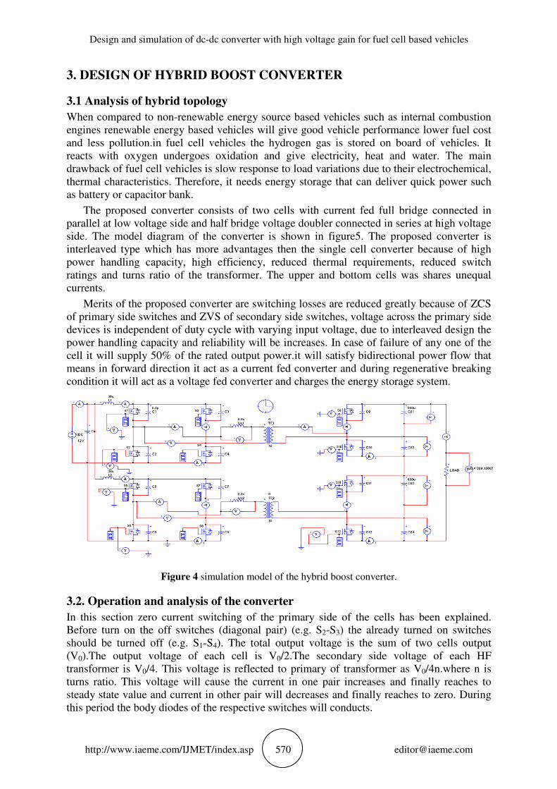
The proposed converter consists of two cells with current fed full bridge connected in
parallel at low voltage side and half bridge voltage doubler connected in series at high voltage
side. The model diagram of the converter is shown in figure5. The proposed converter is
interleaved type which has more advantages then the single cell converter because of high
power handling capacity, high efficiency, reduced thermal requirements, reduced switch
ratings and turns ratio of the transformer. The upper and bottom cells was shares unequal
currents.
Merits of the proposed converter are switching losses are reduced greatly because of ZCS
of primary side switches and ZVS of secondary side switches, voltage across the primary side
devices is independent of duty cycle with varying input voltage, due to interleaved design the
power handling capacity and reliability will be increases. In case of failure of any one of the
cell it will supply 50% of the rated output power.it will satisfy bidirectional power flow that
means in forward direction it act as a current fed converter and during regenerative breaking
condition it will act as a voltage fed converter and charges the energy storage system.
Figure 4 simulation model of the hybrid boost converter.
3.2. Operation and analysis of the converter
In this section zero current switching of the primary side of the cells has been explained.
Before turn on the off switches (diagonal pair) (e.g. S2-S3) the already turned on switches
should be turned off (e.g. S1-S4). The total output voltage is the sum of two cells output
(V0).The output voltage of each cell is V0/2.The secondary side voltage of each HF
transformer is V0/4. This voltage is reflected to primary of transformer as V0/4n.where n is
turns ratio. This voltage will cause the current in one pair increases and finally reaches to
steady state value and current in other pair will decreases and finally reaches to zero. During
this period the body diodes of the respective switches will conducts.

J S V Siva Kumar and P Venkata sateesh
http://www.iaeme.com/IJMET/index.asp 571 [email protected]
The following assumptions are made in order to analysis the study state operation and
analysis of the proposed converter.1. The input boost inductor is assumed as large to make
constant current through it. 2. The output capacitors are assumed as large to make constant
voltage across it 3. By taking all the switches are assumed as ideal.4. Magnetizing inductance
of the transformer is assumed as very large.
In the proposed converter diagonal switch pairs of cell1 (S1-S4) and (S2-S3) are should be
operated with identical gate signals having phase shift of 1800.similarly diagonal switch pairs
of cell2 (S5-S8) and (S6-S7) are should be operated with identical gate signals having phase
shift of 1800.the phase shift between gating signals of (S1-S4) in cell1 and (S5-S8) in cell2 is
900. Similarly the phase shift between gating signals of (S2-S3) in cell1 and (S6-S7) in cell2 is
900. Maintain duty ratio of all the switches should be more than 50%. The gate signals of the
primary and secondary side switches are shown in figure 6.
3.2. Design of the proposed converter
The design of proposed converter is discussed in this section. The following parameters are
required to be designed for converter.
parameter symbol value
Input voltage Vin 12V
Output voltage Vout 300V
Switching frequency fsw 100KHz
Input boost inductors L1,L2 36uH
Snubber capacitors C1-C12 0.5pF
Turns ratio of transformer 1:k 1:2.5
Input capacitor Cin 4.7mF
Output filter capacitors C01- C04 680uF
Leakage inductance of T/F Llk 1.6uF
Duty ratio d% 0.8
Current ripple I∆ 1A
Table 3 Values used for design of boost converter.
A) Determine Boost Inductor Value:
While choosing the inductor, first the most basic parameter is the saturation current of the
inductor. In the event that the saturation current of the inductor is not as much as the converter
required peak current, at that point the converter won't ready to supply the fundamental output
power.
.(d 0.5)
.f
in
s
VL
I
−=
∆
%
(13)
By using above parameters, the inductor value can be calculated according to the
equation.
B) Voltage Gain:
According to volt-sec balance on inductor,
0
in
VM =
V (14)
Design and simulation of dc-dc converter with high voltage gain for fuel cell based vehicles
http://www.iaeme.com/IJMET/index.asp 572 [email protected]
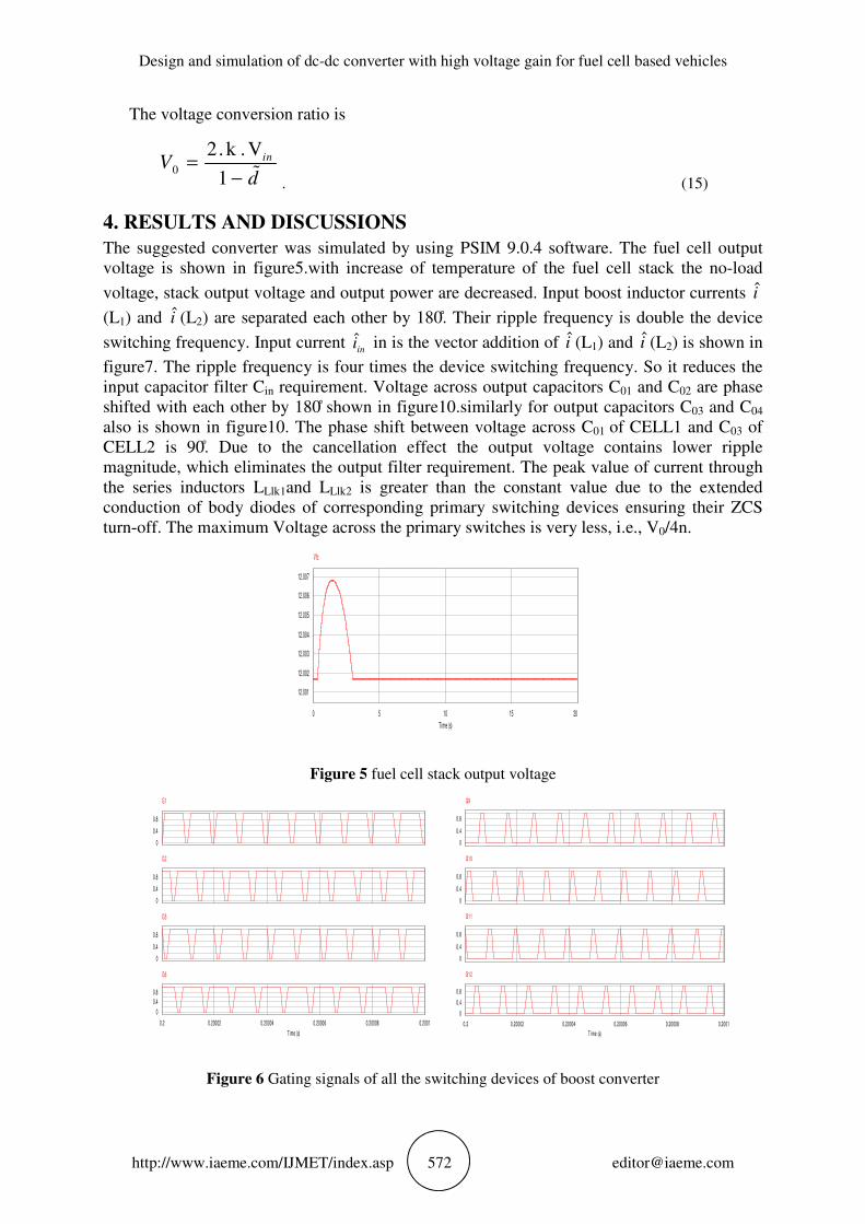
The voltage conversion ratio is
0
2.k .V
1
inVd
=− %
. (15)
4. RESULTS AND DISCUSSIONS
The suggested converter was simulated by using PSIM 9.0.4 software. The fuel cell output
voltage is shown in figure5.with increase of temperature of the fuel cell stack the no-load
voltage, stack output voltage and output power are decreased. Input boost inductor currents i
(L1) and i (L2) are separated each other by 180 . Their ripple frequency is double the device
switching frequency. Input current ˆin
i in is the vector addition of i (L1) and i (L2) is shown in
figure7. The ripple frequency is four times the device switching frequency. So it reduces the
input capacitor filter Cin requirement. Voltage across output capacitors C01 and C02 are phase
shifted with each other by 180 shown in figure10.similarly for output capacitors C03 and C04
also is shown in figure10. The phase shift between voltage across C01 of CELL1 and C03 of
CELL2 is 90 . Due to the cancellation effect the output voltage contains lower ripple
magnitude, which eliminates the output filter requirement. The peak value of current through
the series inductors LLlk1and LLlk2 is greater than the constant value due to the extended
conduction of body diodes of corresponding primary switching devices ensuring their ZCS
turn-off. The maximum Voltage across the primary switches is very less, i.e., V0/4n.
Figure 5 fuel cell stack output voltage
Figure 6 Gating signals of all the switching devices of boost converter
0 5 10 15 20
Time (s)
12.001
12.002
12.003
12.004
12.005
12.006
12.007
Vfc
0
0.4
0.8
G1
0
0.4
0.8
G2
0
0.4
0.8
G5
0.2 0.20002 0.20004 0.20006 0.20008 0.2001
Time (s)
0
0.4
0.8
G6
0
0.4
0.8
G9
0
0.4
0.8
G10
0
0.4
0.8
G11
0.2 0.20002 0.20004 0.20006 0.20008 0.2001
Time (s)
0
0.4
0.8
G12

J S V Siva Kumar and P Venkata sateesh
http://www.iaeme.com/IJMET/index.asp 573 [email protected]
Figure 7 Simulation waveform of input boost inductor currents I(L1 ).
Figure 8 Simulation waveform of voltage Figure 9 Output voltage of boost converter
waveforms VAB and VCD
Figure 10 Voltages across output capacitors Figure 11 voltage waveforms of V (LLlk1), V (LLlk2)
Vco1, Vco1, Vco1 and Vco3.
5. CONCLUSION
The suggested converter is isolated based converter. The proposed converter operates ZCS
turn-off of primary side devices and ZVS turn-on of secondary side devices. Due to which the
switching losses of the converter is very low. Operating frequency of the converter is very
high so that size of the converter is reduces. With interleaved design power handling capacity
increases. The major advantage with this converter, the voltage across the power switches is
0.2 0.20002 0.20004 0.20006 0.20008 0.2001 0.20012
Time (s)
37
37.5
38
38.5
39
IL1
0 0.1 0.2 0.3 0.4 0.5
T ime (s)
0
-100
100
200
300
400
VO
78.2
78.21
78.22
78.23
78.24
VC01 VC02
0.19999 0.2 0.20001 0.20002
Time (s)
77.61
77.62
77.63
77.64
77.65
VC03 VC04
0
-20
20
VLK1
0.20002 0.20004 0.20006 0.20008
Time (s)
0
-20
-40
20
40
VLK2

Design and simulation of dc-dc converter with high voltage gain for fuel cell based vehicles
http://www.iaeme.com/IJMET/index.asp 574 [email protected]
very low. This converter is best for fuel cell based electric vehicle. The performance of the
presented converter will be studied with respect to closed loop control in future.
REFERENCES
[1] U. R. Prasanna, A. K. Rathore, and S. K. Mazumder, Novel zero-current-switching
current-fed half-bridge isolated DC/DC converter for fuel-cell-based applications, IEEE
Trans. Ind. Appl., vol. 49, no. 4, pp. 1658–1668, 2013.
[2] M. Uzunoglu, M. S. Alam, and S. Member, Dynamic Modeling , Design , and Simulation
of a Combined PEM Fuel Cell and Ultracapacitor System for Stand-Alone Residential
Applications, vol. 21, no. 3, pp. 767–775, 2006.
[3] P. Xuewei, S. Member, A. K. Rathore, and S. Member, Novel Interleaved Bidirectional
Snubberless Voltage Doubler for Fuel-Cell Vehicles, vol. 28, no. 12, pp. 5535–5546,
2013.
[4] A. A. Salam, A. Mohamed, and M. A. Hannan, Modeling and Simulation of a PEM Fuel
Cell System Under Various Temperature Conditions, pp. 204–209, 2008.
[5] P. Xuewei and A. K. Rathore, Novel bidirectional snubberless naturally commutated soft-
switching current-fed full-bridge isolated DC/DC converter for fuel cell vehicles, IEEE
Trans. Ind. Electron., vol. 61, no. 5, pp. 2307–2315, 2014.
[6] P. Xuewei and A. K. Rathore, Novel interleaved bidirectional snubberless naturally
clamped zero current commutated soft-switching current-fed full-bridge voltage doubler
for fuel cell vehicles, 2013 IEEE Energy Convers. Congr. Expo. ECCE 2013, pp. 3615–
3622, 2013.
[7] A. Rathore and R. Oruganti, Analysis and Design of Active Clamped ZVS Current-Fed
DC-DC Converter for Fuel-Cell to Utility-Interface Application, no. August, pp. 8–11,
2007.
[8] Sajeev, Shemi P A, Bidirectional Full-Bridge Dc-Dc Converter with Flyback Snubber for
Photovoltaic Applications Indulekha, International Electrical Engineering And
Technology, Volume 5, Issue 12, December (2014), Pp. 233-239
[9] R. Kavitha and V. Rajini, Design and Implementation of a High Gain DC-DC Converter
with Built-in Transformer Voltage Multiplier Cells. International Journal of Electrical
Engineering & Technology, 8(2), 2017, pp. 71–80.
[10] Fernando Santos, Humberto Jorge and Sérgio Cruz, Design of A Multifunctional Flyback
Dc–Dc Converter with Current Control. International Journal of Electrical Engineering &
Technology, 7(3), 2016, pp. 57–72.
[11] Kirti G. More and Ramling D. Patane, Non-Isolated Soft Switching DC-DC Converter and
Load at Full Range of ZVS. International Journal of Electrical Engineering &
Technology, 7(5), 2016, pp. 62–69.