Design and Production Directives for the Construction of ... · ...Page 1 of 40 2011 -08 -26 BMW...
40
...Page 1 of 40 2011-08-26 BMW Group Design and Production Directives for the Construction of Floor Conveyor Equipment
Transcript of Design and Production Directives for the Construction of ... · ...Page 1 of 40 2011 -08 -26 BMW...

...Page 1 of 40
2011-08-26 BMW Group
Design and Production Directives for the
Construction of Floor Conveyor Equipment
...Page 2 of 40
2011-08-26 BMW Group
If you have any queries regarding these Design and
Production Directives, please contact:
Alexander Laue Telephone: +49 (0) 89/382 – 60872 Email: [email protected]
Status: August 2011 All rights reserved. Not to be reproduced wholly or in part.
Supplier home page: https://b2b.bmw.com follow => Departments => Logistics => Packaging => Standards / miscellaneus

...Page 3 of 40
2011-08-26 BMW Group
Contents
Page 1 General directives 4 2 General requirements for floor conveyor equipment (FFG) 5 2.1 EPP standard 5 2.2 ESD protection for packaging 5 3 Materials 6 3.1 Steel grades 6 3.2 Plastics 6 3.3 Disposal of plastics 6 4 Steel tube and section 7 5 Connecting elements 7 6 Base structures 8 6.1 Stacking feet – wire-mesh box pallets 8 6.2 Stacking feet – stacking pins 8 7 Welded joints 11 8 Welding requirements 11 8.1 Weld seams 11 8.2 General quality requirements for welded structures 11 8.3 Drawing of weld seam length for sheet metal 12 9 Floor conveyor equipment lettering/type plate 13 10 Floor conveyor equipment corrosion-proofing/painting 15 11 Design requirements for base 16 11.1.1 Base for 1230 x 830 mm – part list 17 11.1.2 Base for 1230 x 830 mm – drawing 18 11.2.1 Base for >1230 x 830 mm – part list 19 11.2.2 Base for >1230 x 830 mm – drawing 20 12 Stacking frame 21 13 Quality assurance 22 13.1 Inspection during series production 22 14 Use of most recent information 23 14.1 Clarification 23 14.2 Persons to contact 23 14.3 Drawings 23 15 Specific requirements for press shop/body-in-white area 24
16 Standards referred to 29 16.1 DIN standard – general tolerances 31 16.11 General length and angle dimensions 31 16.12 Welded structures: length and angle dimensions 31 16.2 EPP standard 32 16.3 ESD protection 34 16.4 Painting floor conveyors 35 16.5 Hex nuts with locking devices 39

...Page 4 of 40
2011-08-26 BMW Group
1. General directives for floor
conveyor equipment
The quality of our containers and floor conveyor equipment guarantees the quality of parts during the handling process.
To ensure that these high standards are maintained, these
production directives are mandatory.
They form part of a complete quality standard for the design and
production of floor conveyor equipment that is reproducible at any time and complies with DIN ISO 9001.
They establish standards for the materials and also the production
methods and techniques to be used.
The supplier must guarantee that the materials, tubes and sections
listed here have been used in accordance with the DIN and BMW standards quoted here, and that the production methods and techniques described here were employed.
Submission of an offer by the supplier, which must be free of charge,
acknowledges the contents of these Design and Production Directives and undertakes to comply with them.
Deviations from the contents of these directives, and any special
arrangements that are agreed upon, must always be formulated in writing before samples of the floor conveyor equipment are produced or series production commences.
In addition, the General Contractual Terms of BMW AG, with which
the supplier is familiar, remain valid in all respects.

...Page 5 of 40
2011-08-26 BMW Group
2.General requirements for floor
conveyor equipment
All cut edges must be deburred; hollow sections must be deburred internally and externally in all cases. In the case of closed stackable floor conveyor containers the steel outer walls must be moved in by at least 5 mm from the outside of the uprights in order to prevent wear/abrasion during handling. Metal elements that are fully or partly enclosed within plastic, such as PVC hoses, molded film or toothed strip, must be painted first. Panels, pockets for accompanying documents or separately marked, exposed surfaces for documents accompanying the goods must be at least of A5 format and at least 10 mm from the outer surfaces. Such panels or surfaces must be provided with an EVA mesh grill (e.g. Type 0815/60 as supplied by the Norddeutsche Seekabelwerke company), which must be either attached in a weatherproof manner with adhesive or secured with blind rivets. In the case of floor conveyor containers with stacking pins, the upper end section of the uprights is to be reinforced, have a minimum width of 30 mm and be welded on both sides.
2.1 EPP standard BMW’s EPP standard as defined in 16.2 is to be complied with.
2.2 ESD protection for
packaging Packaging materials providing the necessary ESD protection are to be used in accordance with BMW Group Standard 95009 –1/-2.
A copy of this standard will be supplied on request.

...Page 6 of 40
2011-08-26 BMW Group
3. Materials
3.1 Steel grades Fully killed steel of grade S 235 JR G2 according to EN 10 027 and ECISS IC 10 is to be used (former designation of steel: R ST 37-2).
3.2 Plastics ABS Acrylonitrile butadiene styrene PC Polycarbonate PE Polyethylene PU Polyurethane PVC Polyvinyl chloride
PP Polypropylene
PU, PC and PVC are to be used only in special circumstances, for example soft PVC as a jacket for round tube.
DIN 16 940 Permissible dimensions – deviations for soft PVC
hoses
Protefan/Blasoplast Spezial Trade designation of material
supplied by the F. Blasberg company = 55% PVC / 36% plasticizer / 1% pigment, for the plastic coating of metal sections
3.3 Disposal of
plastics 1. The supplier undertakes to take back its plastic products and
subject them to an approved recycling process.
2. Plastic materials must be marked with pictorial symbols and
identification codes as laid down in DIN 6120.

...Page 7 of 40
2011-08-26 BMW Group
4. Steel tube and section
The steel tubes and sections used must comply with: DIN 2394 Welded precision steel tube rolled to dimension DIN 2395 Welded precision steel tube of rectangular or square cross-
section
DIN 1028 Hot-rolled steel angle with uniform side length and rounded edges DIN 1017 Hot-rolled steel strip DIN 1026 Hot-rolled U-section steel with rounded edges DIN 1541 Cold-rolled sheet
5. Connecting elements Only galvanized or nickel-plated bolts, screws and locknuts or those of higher
quality are to be used for threaded connections (customary commercial forms: blue galvanized/yellow galvanized).
Only bolts and screws of strength category 8/K are to be used. BMW N 113 39.0
Hex nuts with locking device; BMW standard based on DIN 6924
DIN 7337
Blind rivet with galvanized steel pin
(head sizes: small 11mm – large 14mm)
Spring lock: Cadmium-plated or higher quality
Examples of recommended manufacturers: - Femma - Hahn - Viebahn
Version with weld tag or thread.

...Page 8 of 40
2011-08-26 BMW Group
6. Base structures
6.1 Stacking feet – wire-mesh box pallets
- (Box pallet with stacking feet, DIN 15 555), drawing No. 3102537 used for base section 820 mm wide (see Page 9)
- (Stacking pins) used for square tube, 40 x 3 mm
6.2 Stacking feet – stacking pins
- (Stacking pins) drawing No. 3100418 used for square tube, 50 x 4 mm (see Page 10)
- (Stacking pins) drawing No. 3100119
used for square tube, 60 x 3.5 mm

...Page 9 of 40
2011-08-26 BMW Group
6.1 Stacking feet – box pallets

...Page 10 of 40
2011-08-26 BMW Group
6.2 Stacking feet – stacking pins
...Page 11 of 40
2011-08-26 BMW Group
7. Welded joints
Requirements: DIN 18 800 Part 7 Shorter welding test certificate Persons carrying out welding work must hold the shorter welding test certificate.
Welding methods: MIG metal arc – inert-gas welding
MAG metal arc – active gas welding
8. Welding requirements
8.1 Weld seams DIN EN 25 817 assessment group C (C = medium) All weld seams must comply with this standard unless other
requirements are imposed.
8.2 General quality
requirements for welded structures
Vertical tubes are to be welded at top and bottom and provided with a water drain at the lowest point.
Exception: End frame for press shop (see Page 39).
Sheet metal panels must always be welded on.
Corners must be through-welded to min. 15 x 15 mm.
On straight sections the weld seams must be approx. 15 – 20 mm
long; at least 30% of the total length must be welded, with the weld seams distributed symmetrically over the full length (see Chapter 8.3).
At sheet metal panels (including bases), overlap with the supporting
sections must not exceed 5 mm (see Chapter 8.3).
Lids or covers that extend beyond the outer contour of the floor
conveyor container must cover the vertical sheet metal panels.

...Page 12 of 40
2011-08-26 BMW Group
8.3 Drawing of weld seam length for sheet metal

...Page 13 of 40
2011-08-26 BMW Group
9. Floor conveyor equipment
lettering/type plate
All floor conveyor equipment (German abbreviation: FFG) is to be marked with the FFG Ident. No., the component name, the BMW emblem and an indication of BMW ownership. Lettering on the FFGs should be of the maximum possible size for better legibility.
The conversion status of floor conveyor equipment must also be
shown so that it can be identified. This form of identification (painting) must be applied to the diagonally opposed outer faces of the uprights (minimum height of painted identification 200 mm from top). The conversion status is to be indicated by the following colors:
Conversion status A (1st modification): Signal blue, RAL 5005 Conversion status B (2nd modification): Ivory, RAL 1014 Conversion status C (3rd modification): Pure orange, RAL 2004
This identification is repeated on the floor conveyor container as “Stand (status) X” after the Ident. No.
Identification paint/ink: black/white In the case of special floor conveyor containers with rigid paneling, the FFG Ident. No. is to be applied by flexographic printing on all four sides, if possible using a color in strong contrast to the surface color.
If two or more containers are identical (left-hand drive/right-hand drive, containers of similar appearance for different suppliers etc.), these must at least be marked diagonally over the corner of each upright.
All floor conveyor equipment must carry the manufacturer’s mark. Regulation ZH 1/428 issued by the Süddeutsche Metall- and
Berufgenossenschaft (South German Metal Trades and Industrial Accident Insurers) calls for floor conveyor equipment to be additionally marked to show the permissible payload and supported load separately. This regulation is complied with by the standardized BMW type plate as follows:

...Page 14 of 40
2011-08-26 BMW Group
Design requirements The following information is to be stamped on the type plate (see
drawing in Annex):
BMW emblem with inscription “Eigentum BMW AG” for German plants; for foreign plants: “Property BMW” plus the appropriate legal form) Exception: For containers used both within Germany and abroad, the lettering must be neutral (“Eigentum BMW/Property BMW”), for instance as on 310 1860 containers.
FFG No. of the container (large)
Permissible payload
Permissible supported load
Tare weight
Year of manufacture
FFG manufacture/place of manufacture
Position: If possible on the front of the left or right uprights, but not on the outside of the container; 200mm from the top of the base frame, otherwise as individually appropriate
Attachment: by 3 blind rivets with 4.5mm dia. holes (aluminum river sleeve, galvanized steel rivet pin) with mushroom head, shank diameter = 4mm Clamping length as required (depending on thickness of material at attachment point); rivet head diameter: 10mm
Type plate dimensions: 175 mm x 28 mm x 0.5 mm
Material: stainless steel
Pattern: corners of type plate rounded off

...Page 15 of 40
2011-08-26 BMW Group
Eigentum
BMW
2310 4444Nutzlast [40] kg
Auflast [3000] kg
Tara [180] kg
Baujahr [1999] Geb
har
dt
Pal
ette
n
93413 C
ham
2mm
4,5 mm
96 mm
175 mm
28 m
m
Eigentum
BMW
2310 4444Nutzlast [40] kg
Auflast [3000] kg
Tara [180] kg
Baujahr [1999] Geb
har
dt
Pal
ette
n
93413 C
ham
2mm
4,5 mm
96 mm
175 mm
28 m
m
Schematic design drawing of type plate, with dimensions
10. Floor conveyor equipment corrosion-proofing/painting
Painting of floor conveyor equipment Floor conveyor s are to be painted in accordance with BMW Group Standard GS 97001 (see Chapter 16.4); the minimum coating thickness must be 60 μ. Container colors: Universal containers: RAL 4008 signal violet Special containers: RAL 6027 light green

...Page 16 of 40
2011-08-26 BMW Group
11. Design requirements for base
In all cases, lower struts (connecting the two stacking feet) must be
attached at a length of ≥1250 mm as shown in the drawing (11.2).
Lower struts are to be provided at the material removal side and one
narrower side (end).
Stacking shoes (insertion aids) are to be attached diagonally at a
minimum spacing of 620 mm.
Stacking feet should be welded all round on the outside. Please refer to the design drawings for details of the design directives to
be complied with.
Design drawings for the following base assemblies:

...Page 17 of 40
2011-08-26 BMW Group
11.1.1 Base for 1230 x 830 mm – part list Weld seams without specific details: welded all round to DIN EN 25817-C general tolerances
for welded structures; lengths and angle dimensions: DIN EN ISO 13920–A All cut edges must be deburred.

...Page 18 of 40
2011-08-26 BMW Group
11.1.2 Base for 1230 x 830 mm – drawing

...Page 19 of 40
2011-08-26 BMW Group
11.2.1 Base for > 1230 x 830 mm – part list
Space beneath base between feet, free-standing container: 100 mm; when stacked: min. 65 mm. Length of foot min. 200 mm, width of foot min. 70 mm, all lower and outer edges rounded off, no projecting weld seams. Base of containers suitable for high-bay stores closed from the outside for min. 200 mm on each longer side. Weld seams without specific details: all round, to DIN EN 25817-C standard. General tolerances for welded structures, lengths and angles: DIN EN ISO 13920–A All cut edges must be deburred.

...Page 20 of 40
2011-08-26 BMW Group
11.2.2 Base for > 1230 x 830 mm – drawing

...Page 21 of 40
2011-08-26 BMW Group
12. Stacking frame
When stacked, the maximum stacking clearance (difference
between stacking and stacking foot angles)must be 20 mm.
Insertion depth when stacked min. 30 mm. Metal bars at the end of the stacking angles must be welded
inside and out.
The stacking frame for the 1240 x 835 mm base must be
designed to accept all base/foot designs with corner-to-corner dimensions of 1200 x 800 mm.
If the stacking angle is > 50 mm, a horizontal water drain hole with
a minimum diameter of 10 mm is to be provided centrally.

...Page 22 of 40
2011-08-26 BMW Group
13. Quality assurance
The supplier is responsible for the quality of all the containers it
produces.
13.1 Inspection during
series production Outturn samples
A production outturn sample is to be submitted before series
production starts. The auxiliary equipment, gauges and fixtures intended for series production are to be used to make this sample. The relevant department of BMW AG will state the place at which acceptance of the series-production outturn sample is to take place. The series-production outturn sample must be identified as such.
Acceptance for series production Before series production containers are delivered, either
BMW AG employees or independent testers commissioned by BMW AG (e.g. SGS-Controll Co. or TÜV) will carry out a quality and function test.. For this reason, the relevant planner at BMW AG is to be notified at least two weeks in advance of the intended date of delivery and a date for the acceptance inspection agreed.
If quality or functional defects are detected during this inspection,
they must be rectified free of charge by the supplier, who must take the agreed delivery schedule into consideration.

...Page 23 of 40
2011-08-26 BMW Group
14. Use of most recent information
The supplier must make sure that the sample container is manufactured in all cases in accordance with the most recent valid issues of the relevant BMW standards, DIN standards and the current production component specification.
The supplier is responsible for acquiring the DIN standards
mentioned in this directive.
Source: Beuth Verlag GmbH,
Burggrafenstrasse 6, 10787 Berlin, Germany
BMW’s internal standards are included in the Annex. 14.1 Clarification Before submitting an offer the supplier must clarify with the
responsible departments all technical queries that could arise as a result of differences in the interpretation or application of drawings, standards or the sample container.
Deviations from the specified standards or drawings are not
permitted without prior consultation with and written confirmation from the responsible BMW AG departments.
14.2 Persons to contact If any queries arise, please contact the planners in the relevant
departments.
14.3 Drawings If the supplier produces drawings, they must take the general
directives and BMW N 11332.0 T1 into account and be provided with a BMW text panel.

...Page 24 of 40
2011-08-26 BMW Group
15. Specific requirements for press shop/body-in-white area
BMW AG
Press shop/body-in-white areas Logistic planning and control Technical supply conditions
Construction of containers for the press shop/body-in-white areas

...Page 25 of 40
2011-08-26 BMW Group
Basic information on the construction of special containers
The special containers used by BMW AG for the transportation and delivery of components normally consist of a standard outer frame and an insert matched to the component being carried.
The standard frame consists of a base frame tat can be made in various
sizes, and two end frames or individual uprights. The base has a wire-mesh surface and may be equipped with width extensions.
Fig. 1: Special container construction
The standard frame (rack) elements are stocked on behalf of BMW AG by the Gillhuber company in Garching-Hochbrück (Gutenbergstrasse 29, 85748 Garching, Germany) and can be collected from there by agreement with the responsible BMW department.

...Page 26 of 40
2011-08-26 BMW Group
Rack components
The table below lists the rack components in regular use and their dimensions. Rack components are pre-painted.
Non-standard sizes may only be used after confirmed approval has been
obtained from the Press Division.
Table 1: Standard rack component dimensions
Customary base frame sizes (in mm) 1000 x 1200 2000 x 1200 2200 x 1200 2400 x 1200 2500 x 1200 3000 x 1200 3200 x 1200 3500 x 1200 3700 x 1200 3800 x 1200 4000 x 1200
Customary end frame sizes (in mm), 500 x 1200 1200 mm wide 750 x 1200 1000 x 1200 1250 x 1200 1500 x 1200 1750 x 1200
1000 mm wide 500 x 1200 750 x 1200 1000 x 1200
Customary width extension sizes (in mm)
50 x Base frame length
100 x Base frame length 150 x Base frame length 200 x Base frame length 250 x Base frame length 300 x Base frame length
Customary sizes of uprights (in mm) 500
750
1000
1250
1500
1750
Customary wire-mesh base assemblies Depending on base frame dimensions

...Page 27 of 40
2011-08-26 BMW Group
Lettering All containers are to be marked with a container serial number, component designation, model designation and Ident. No. on the outside of the end frame cross-member.
Lettering templates for container marking will be supplied by BMW AG free of charge; the paint color for the lettering is black.
Fig. 2: Markings on special containers
...Page 28 of 40
2011-08-26 BMW Group
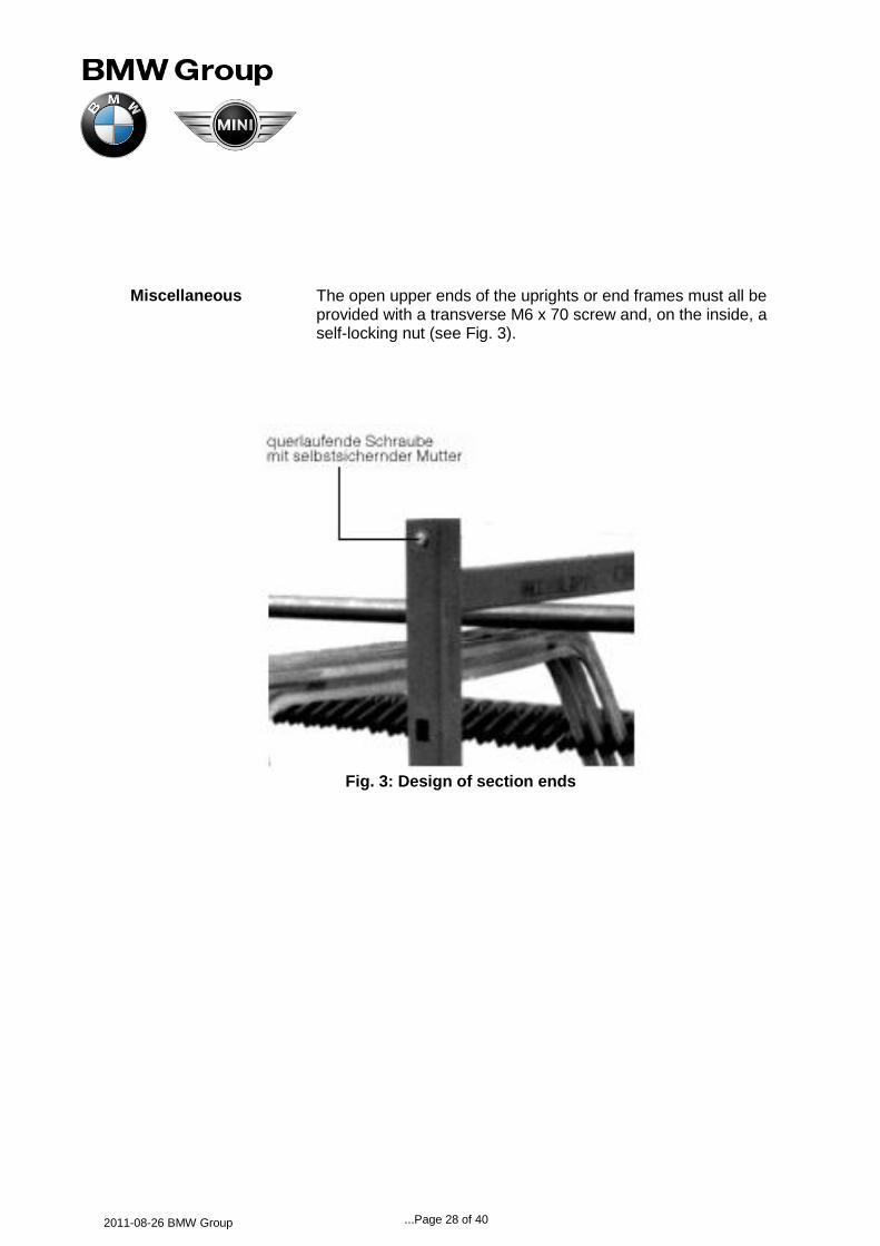
Miscellaneous The open upper ends of the uprights or end frames must all be provided with a transverse M6 x 70 screw and, on the inside, a self-locking nut (see Fig. 3).
Fig. 3: Design of section ends

...Page 29 of 40
2011-08-26 BMW Group
16. Standards referred to
DIN ISO 9 001 Quality assurance systems; Model for presentation of quality
assurance in Design/Development, Production, Assembly and After Sales Service
DIN EN 10 025 Hot-rolled non-alloyed steel products
DIN 16 940 Permissible dimensions – deviations for PVC hoses
DIN2394-1 Welded precision steel tube rolled to dimension; dimensions
DIN 2394-2 Welded precision steel tube rolled to dimension; technical delivery conditions
DIN-2395 Welded precision steel tube rolled to dimension; rectangular or square cross-section
DIN 1028 Hot-rolled steel angle with rounded edges and sides of equal length
DIN 1029 Hot-rolled steel angle with rounded edges and sides of unequal length
DIN 1017 Hot-rolled steel strip
DIN 1026 Hot-rolled U-section steel channels with rounded edges
DIN 1541 Cold-rolled sheet metal
DIN 6924 Hex nuts with locking device
DIN 7337 Blind rivets with galvanized steel pin
DIN 15 155 Stacking feet for wire-mesh box pallets
DIN 18 800 Part 7 Shorter welding certificate
DIN EN ISO 13 920 General tolerances for welded structures

...Page 30 of 40
2011-08-26 BMW Group
DIN EN 25 817 Arc welded joints in steel
DIN ISO 2768 General tolerances Length and angle tolerances if not stated individually
BMW N 113 39.0 Hex nut with locking device (DIN 6924)
BMW GS 97001 Painting floor conveyor equipment
BMW N 113 32.0 T1 Technical drawings
BMW GS 95009 –1 / 2
ESD standard
Supplier of DIN standards:
Beuth Verlag GmbH, Burggrafenstrasse 6, 10787 Berlin, Germany

...Page 31 of 40
2011-08-26 BMW Group
16.1 DIN standard – general tolerances
16.11 Lengths and
angles, general General tolerances according to DIN ISO 2768 – m: Length and angle tolerances
16.12 Welded structures:
lengths and angles DIN EN ISO 13 920-A (A =tolerance class)
Length limits

...Page 32 of 40
2011-08-26 BMW Group
16.2 EPP standard
Ident. No. label
Material: PP (polypropylene, suitable for recycling)
Number of labels/foam trays: 2
Position, layout, type of text, content: see Annex, Examples 1 and 2
Minimum text area size: 200 mm x 40 mm
Colors: Text: black; background: white
Recommended: corners rounded off for greater durability
Position the label such that it remains visible even if the hinged doors of external container 3101860 are closed, in other words at least 150 mm away from each edge on the longer side of the foam tray (see drawing). Check the necessity of also applying a label of maximum size along the transverse sides of each foam tray (marking on all four sides).
Minimum wall and base thicknesses, height of stacking edge: see Annex, Example 2
Handle recess size: 80 mm x 10 mm x 10 mm slightly cut away, centrally located on both sides
Chamfers and rounded-off edges to suit BMW requirements
Stacking edge on two opposed sides, in each case on the shorter side in the tray removal direction; see Annex, Example 2
For the 310 1860 external container, all the permissible EPP foam trays are shown as a table in the Annex; see Annex, Example 3
CA models: see Annex, Example 2 3D CAD models of the EPP trays in format CATIA V5, STEP and IGES have been finalized as 3D CAD models (geometric versions)
to be taken over for specific EPP containers. The CATIA V5 data set contains a parametrically built-up model with the complete table. 3D CA models are available in STEP and IGES formats for all external dimensions and for 5 heights as examples (stacking factor 2, 6, 10, 14 and 18). The data can be located on the Internet at: http://zulieferer.bmw.de/tec/coc/tm/cad/container/intro.html
Konstruktive Ausführung

...Page 33 of 40
2011-08-26 BMW Group
Characteristic material values – EPP
Color of material: black (exceptions are possible)
Minimum tensile strength acc. to DIN 53571: 880 kPa
Minimum density: 60 g/l (tolerance: +/- 10%)
For component that must comply with BMW’s ESD protection requirements, the surface resistance according to DIN EN 61340-5-1/2 is to be complied with throughout the EPP foam tray material
Annex Example 1: Original format and specimen text for lettering panel (with ESD protection symbol)
Example 2: Layout of inscription label on foam tray:
front view of EPP foam tray with stacking edge on two sides:

...Page 34 of 40
2011-08-26 BMW Group
Example 3: Standard table of dimensions – EPP foam tray for 310 1860
Note:
A lid or cover for the uppermost layer of the EPP foam tray, for example a 310 4802 intermediate-layer cover, is recommended to avoid contamination, damage etc.
16.3 ESD protection (see Chapter 2.2)

...Page 35 of 40
2011-08-26 BMW Group
Konzern Norm GS 97001 Group Standard Mai/May 1999
Deskriptoren: Flurfördergerät, Lackierung Ersatz für BMWN 60130.0: 1996-04 Descriptors: Floor conveyor, Painting Supersedes BMW S 60130.0: 1996-04
16.4 Lackierung von Flurfördergeräten
Anforderungen und Prüfungen
Painting of containers
Requirements and testing
Ausdrucke unterliegen nicht dem Änderungsdienst
Print-outs are not subject to the change service
Fortsetzung Seite 2 bis 4
Continued on pages 2 to 4
BMW AG Normung Konzern 80788 München
© BMW AG Alle Rechte vorbehalten All rights reserved
interleaf-doc

...Page 36 of 40
2011-08-26 BMW Group
In case of dispute the German wording shall be valid.
Inhalt
Seite 1 Anwendungsbereich und Zweck 2 2 Normative Verweisungen 3 3 Zeichnungseintragung 3 4 Beschichtungsverfahren 3 4.1 Verfahren A 3 5 Anforderungen 3 5.1 Allgemeines 3 5.2 Lack 4 5.3 Schichtdicke 4 6 Prüfungen 4 6.1 Klimatische Beständigkeitsprüfung 4 6.2 Mechanische Prüfung 4
Vorwort
Diese Konzern Norm wurde mit den verantwortlichen Bereichen des BMW Konzerns abgestimmt.
Änderungen
Gegenüber der BMWN 60130.0: 1996-04 wurden folgende
Änderungen vorgenommen:
– In Konzern Norm umgewandelt
– Die englische Übersetzung wurde aufgenommen
– Das Beschichtungsverfahren B wurde gestrichen
– Die Norm wurde redaktionell überarbeitet
Frühere Ausgaben
BMWN 60130.0: 1987-11; 1996-04
1 Anwendungsbereich and Zweck
Diese Konzern Norm gilt für die Lackierung von Metallteilen
in Flurfördergeräten (z.B. Behälter, Paletten).
Holz- and Kunststoffteile bleiben, sofern nicht anders
angegeben, unlackiert.
Es werden die Anforderungen an die Lackqualität und die
entsprechenden Prüfungen festgelegt.
Contents
Page 1 Scope and purpose 2 2 Normative references 3 3 Drawing entry 3 4 Coating process 3 4.1 Process A 3 5 Requirements 3 5.1 General information 3 5.2 Paint 4 5.3 Layer thickness 4 6 Tests 4 6.1 Weathering resistance test 4 6.2 Mechanical test 4
Foreword
This Group Standard has been coordinated with the responsible departments of the BMW Group.
Amendments
The following amendments have been made to
BMW S 60130.0: 1996-04:
– Converted into Group Standard
– English translation added
– Coating process B deleted
– Standard editorially revised
Previous editions
BMW N 60130.0: 1987-11; 1996-04
1 Scope and purpose
This standard is applicable to the paint finish of metal parts
in floor conveyors (e.g. boxes, containers, pallets).
Wooden and plastic parts remain unpainted, unless
otherwise specified.
The requirements posed and the paint quality and
corresponding tests are specified.

...Page 37 of 40
2011-08-26 BMW Group
2 Normative Verweisungen 2 Normative references
Diese Norm enthält Festlegungen aus anderen Publikationen. Diese normativen Verweisungen sind an den jeweiligen Stellen im Text zitiert und die Publikationen sind nachstehend aufgeführt. Es gilt die letzte Ausgabe der in Bezug genommenen Publikation.
This standard incorporates provisions from other publications. These normative references are cited at the appropriate places in the text and the publications are listed hereafter. The respective latest edition of the publication is applicable.
DIN EN ISO 2409 Lacke und Anstrichstoffe;
Gitterschnittprüfung DIN EN ISO 2409 Paints and varnishes;
cross-cut test VDA 621-402 Anstrichtechnische Prüfungen;
Salzsprühnebelprüfung an Anstrichen und ähnlichen Beschichtungen
VDA 621-402 Paint-coating-related tests; Salt spray test on paints and similar Coatings
RAL 840 HR Farbregister RAL 840 HR Color register
3 Zeichnungseintragung
3 Drawing entry
Der Zeichnungseintrag erfolgt im Schriftfeld unter Ober-
flächenbehandlung oder in der Nähe des Schriftfeldes. The relevant data are entered in the title block in the
field Surface Treatment or in close proximity to the title block.
Bezeichnung einer Lackierung für ein Flurfördergerät (FFG),
im Farbton RAL 4008: Designation of a paint finish for a floor conveyor
(German: Flurfördergerät – FFG), Process A in color RAL 4008:
GS97001-FFG-A-RAL-4008 GS97001-FFG-A-RAL-4008 Andere Farben nach RAL-Farbregister. Other colors according to RAL-Color-Register. 4 Beschichtungsverfahren 4 Coating process Der Oberflächenschutz wird durch eine lufttrocknende,
witterungsbeständige Lackierung erreicht die in zwei Schichten als Grundierung and Decklackierung aufgebracht wird. Die Grundierung ist in einem von der Decklackierung abweichenden Farbton auszuführen. Die Prüfbedingungen nach Abschnitt 6 sind zu erfüllen.
Surface protection is effected by means of an air-drying paint coat which is resistant to weathering. Two layers of paint coat are applied as base coat and top coat. Application of the primer is to be in a color different from the top coat. The test requirements specified in section 6 must be met.
5 Anforderungen 5 Requirements 5.1 Allgemeines 5.1 General information Der Untergrund muß vor der Lackierung von Rost, Zunder,
Fett, Staub und sonstigen Verunreinigungen vollständig befreit sein. Die Lackierung muß auf dem Untergrund gut haften und darf die Funktion nicht beeinträchtigen.
Prior to application of the paint coat, scale, grease, dust or any other pollutants must be completely removed from the surface. The paint coat must show good adhesive strength and must not impair the function of the component.
5.2 Lack 5.2 Paint Die Lacke dürfen keine blutenden Pigmente und kein
Silikon enthalten. Die Farben werden aus dem RAL-Farbregister 840 HR gewählt.
The paint must not contain pigments that bleed out or silicones. The colors are selected from RAL color register 840 HR.
5.3 Schichtdicke 5.3 Layer thickness Unabhängig vom Beschichtungsverfahren ist eine Gesamt-
schichtdicke von 60 μm einzuhalten, die auch an Blech- und Profilschnittkanten und anderen schwer zugänglichen Stellen erreicht werden muß.
Irrespective of the coating process a total paint coat thickness of 60 μm must be built up, including sheet-and profile cutting edges and other areas with difficult access.

...Page 38 of 40
2011-08-26 BMW Group
6 Prüfungen 6 Tests 6.1 Klimatische Beständigkeitsprüfung 6.1 Weathering resistance test 6.1.1 Salzsprühnebelprüfung
Die Prüfung erfolgt nach dem VDA-Prüfblatt 621-402, geforderte Note Wd ≤2 mm. Die Testdauer beträgt 72 Stunden.
6.1.1 Salt spray test Testing is in accordance with VDA test sheet 621-402, required grade Wd ≤2 mm. The test duration is 72 hours.
6.2 Mechanische Prüfung 6.2 Mechanical test 6.2.1 Gitterschnittprüfung
Die Prüfung erfolgt nach DIN EN ISO 2409, geforderte Note ≤2. Lose anhaftende Lackteilchen werden mit Klebeband vorgegebener Klebekraft (entsprechend 4651 Fa. Beiersdorf) entfernt.
6.2.1 Cross-cut test Testing is in accordance with DIN EN ISO 2409, required grade ≤2. Loosely adhering paint particles are removed with adhesive tape of specified adhesive power (equivalent to 4651, supplier Beiersdorf).

...Page 39 of 40
2011-08-26 BMW Group
16.5 Hex nuts with locking device BMW Works Standard
(non-metallic insert) 113 39.0
Dimensions in mm Ersatz für Ausgabe 08.88
1 Drawings This standard is based on German Industrial Standard DIN 6924.
This standard contains requirements for hex nuts with a locking element (a non-metallic insert), with metric thread and a nominal thread diameter of 4 to 16 mm, in Product Class A.
2 Dimensions
Table 1: Dimensions
M4 M5 M6 M(7) M8 M10 M12 (M14) M16
Thread d - - - - M8x1 M10x1 M12x1.5 (M14x1.5) M16x1.5
P1)
0.7 0.8 1 1 1.25 1.5 1.75 2 2
da min. 4 5 6 7 8 10 12 14 16
max. 4.6 5.75 6.75 7.75 8.75 10.8 13 15.1 17.3
dw min. 5.9 6.9 8.9 9.6 11.6 14.6 16.6 19.6 22.5
e min. 7.66 8.79 11.05 12.12 14.38 17.77 20.03 23.35 26.75
h min. 6 6.8 8 9 9.5 11.9 14.9 17 19.1
max. 5.7 6.44 7.64 8.64 9.14 11.47 14.47 16.3 18.26
m min.2)
2.9 4.4 4.9 6.14 6.44 8.04 10.37 12.1 14.1
m` min. 2.32 3.52 3.92 4.91 5.15 6.43 8.3 9.68 11.28
s Nom. dim. = max.
7 8 10 11 13 16 18 21 24
min. 6.78 7.78 9,78 10,73 12,73 15,73 17,73 20,67 23,67
Threads shown in brackets should be avoided if possible. 1)
P = Regular thread pitch according to DIN 13 Part 12. 2)
Also minimum thread height Note: Preference should be given to the use of hex nuts according to BMW N 113 38.0.

Page 40 of 40
2011-08-26 BMW Group
3 Technical delivery conditions
Table 2: Requirements
Material Steel
General requirements acc. to DIN 267 Parts 1 and 15
Thread Tolerance 6H1)
Standard DIN13 Part 15
Mechanical properties Strength class 8, 10; 12 (body of nut) (material)
Standard DIN ISO 898 Part 2, DIN 267 Part 23
If boron-alloyed material is used, the grade must be at least 35 B2 acc. to DIN 1654 Part 4 for strength class 12.
Material (locking ring) PA 66, heat resistant
Tightening torques acc. to BMW N 600 02.0
Functional properties acc. to DIN 267 Part 15, but surface of test screw in
strength class 8: ZN, in classes 10 and 12: PHR
Dimensional limits, Product class A (previously m) shape and position tolerances
Standard DIN ISO 4759 Part 1
Surface As manufactured
Surface roughness: DIN 267 Part 2 applies
Permissible surface flaws: DIN 267 Part 20 applies
Marking Strength class 8: lock ring dyed blue
Strength class 10: lock ring dyed white
Strength class 12: lock ring dyed red
Additional marking according to DIN 267 Part 15 is
permitted.
Surface protection According to BMW N 600 00.0
Lubricant The lubricant must possess properties that enable
tightening torques and preload values according to
BMW N 600 02.0 to be guaranteed.
Acceptance test DIN 267 Part 5 applies
1) Thread tolerance 6 H applies to nuts either with or without surface protection.
4 Designation
Designation of a hex nut with locking device (non-metallic insert), with thread d = M12, strength class 8 and ZN surface:
Sechskantmutter BMW N 113 39.0 – M12 – 8 – ZN
(hex nut)
Notes: Thread projection acc. to DIN 78, but at least 2P Nuts are not to be re-used. Authorized suppliers: subject to supplier approval