Design and Preliminary Field Validation of a Fully …gear.mit.edu/papers/knee/jmr2016.pdfDesign and...
30
ASME Journal of Mechanisms and Robotics 1 Design and Preliminary Field Validation of a Fully Passive Prosthetic Knee Mechanism for Users with Transfemoral Amputation in India V. N. Murthy Arelekatti Graduate Research Assistant Global Engineering and Research Laboratory Department of Mechanical Engineering Massachusetts Institute of Technology, Cambridge, Massachusetts 02139 Email: [email protected] Student Member of ASME Amos G. Winter, V Assistant Professor Global Engineering and Research Laboratory Department of Mechanical Engineering Massachusetts Institute of Technology, Cambridge, Massachusetts 02139 Email: [email protected] Member of ASME ABSTRACT An estimated 230,000 above-knee amputees in India are currently in need of prosthetic devices, a majority of them facing severe socio-economic constraints. However, only a few passive prosthetic knee devices in the market have been designed for facilitation of normative gait kinematics and for meeting the specific daily life needs of above-knee amputees in the developing world. Based on the results of our past studies, this paper establishes a framework for designing a potentially low-cost, fully passive prosthetic knee device, which aims to facilitate able-bodied kinematics at a low metabolic cost. Based on a comprehensive set of functional requirements and biomechanical analysis from our past work, we present an early prototype mechanism for the prosthetic knee joint that is primarily focused on enabling able- bodied kinematics. The mechanism is implemented using two functional modules: an automatic early stance lock for stability and a differential friction damping system for late stance and swing control. For preliminary, qualitative validation of the knee mechanism, we carried out a field trial on four above-knee amputees in India, which showed satisfactory performance of the early stance lock. The prototype enabled
Transcript of Design and Preliminary Field Validation of a Fully …gear.mit.edu/papers/knee/jmr2016.pdfDesign and...

ASME Journal of Mechanisms and Robotics
1
Design and Preliminary Field Validation of a Fully Passive Prosthetic Knee Mechanism for Users with
Transfemoral Amputation in India V. N. Murthy Arelekatti Graduate Research Assistant Global Engineering and Research Laboratory Department of Mechanical Engineering Massachusetts Institute of Technology, Cambridge, Massachusetts 02139 Email: [email protected] Student Member of ASME Amos G. Winter, V Assistant Professor Global Engineering and Research Laboratory Department of Mechanical Engineering Massachusetts Institute of Technology, Cambridge, Massachusetts 02139 Email: [email protected] Member of ASME ABSTRACT
An estimated 230,000 above-knee amputees in India are currently in need of prosthetic devices, a
majority of them facing severe socio-economic constraints. However, only a few passive prosthetic knee
devices in the market have been designed for facilitation of normative gait kinematics and for meeting the
specific daily life needs of above-knee amputees in the developing world. Based on the results of our past
studies, this paper establishes a framework for designing a potentially low-cost, fully passive prosthetic
knee device, which aims to facilitate able-bodied kinematics at a low metabolic cost. Based on a
comprehensive set of functional requirements and biomechanical analysis from our past work, we present
an early prototype mechanism for the prosthetic knee joint that is primarily focused on enabling able-
bodied kinematics. The mechanism is implemented using two functional modules: an automatic early
stance lock for stability and a differential friction damping system for late stance and swing control. For
preliminary, qualitative validation of the knee mechanism, we carried out a field trial on four above-knee
amputees in India, which showed satisfactory performance of the early stance lock. The prototype enabled
ASME Journal of Mechanisms and Robotics
2
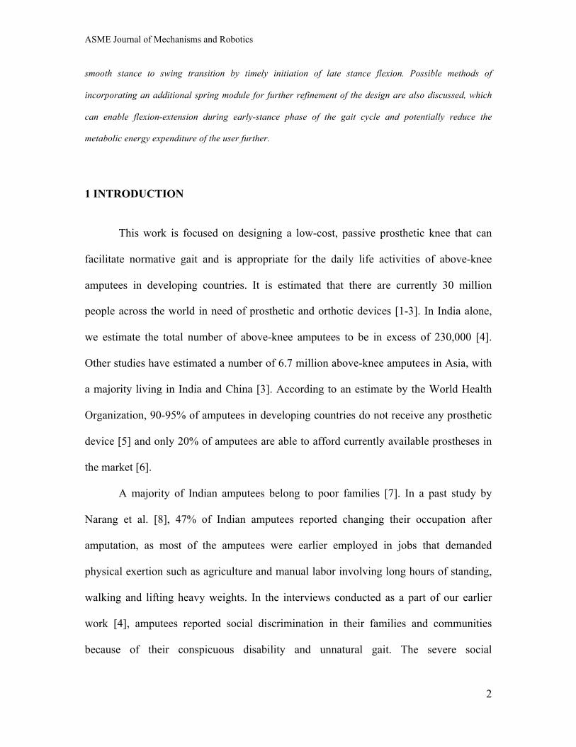
smooth stance to swing transition by timely initiation of late stance flexion. Possible methods of
incorporating an additional spring module for further refinement of the design are also discussed, which
can enable flexion-extension during early-stance phase of the gait cycle and potentially reduce the
metabolic energy expenditure of the user further.
1 INTRODUCTION
This work is focused on designing a low-cost, passive prosthetic knee that can
facilitate normative gait and is appropriate for the daily life activities of above-knee
amputees in developing countries. It is estimated that there are currently 30 million
people across the world in need of prosthetic and orthotic devices [1-3]. In India alone,
we estimate the total number of above-knee amputees to be in excess of 230,000 [4].
Other studies have estimated a number of 6.7 million above-knee amputees in Asia, with
a majority living in India and China [3]. According to an estimate by the World Health
Organization, 90-95% of amputees in developing countries do not receive any prosthetic
device [5] and only 20% of amputees are able to afford currently available prostheses in
the market [6].
A majority of Indian amputees belong to poor families [7]. In a past study by
Narang et al. [8], 47% of Indian amputees reported changing their occupation after
amputation, as most of the amputees were earlier employed in jobs that demanded
physical exertion such as agriculture and manual labor involving long hours of standing,
walking and lifting heavy weights. In the interviews conducted as a part of our earlier
work [4], amputees reported social discrimination in their families and communities
because of their conspicuous disability and unnatural gait. The severe social
ASME Journal of Mechanisms and Robotics
3
consequences and stigma endured by people who undergo lower-limb amputation in the
context of different cultures have been well documented [10-12]. Acute financial
constraints coupled with socio-economic considerations project an urgent need for a low-
cost product that can deliver high levels of functional performance.
Although a number of advanced prosthetic limbs and assistive devices have been
designed for the developed world in the last few decades (Fig. 1), very few of them have
been suitable for large-scale use in developing countries due to vastly different and
complex socio-economic considerations and resource-constrained settings. Prosthetic
knee joints in the United States and Europe cost several thousand dollars to manufacture
and distribute. Popular active above-knee prostheses that deliver very high performance
can cost more than $50,000 [13]. Even the passive knee joints in developed countries are
too expensive to meet the requirements of amputees in the developing world.
In biomechanical terms, the cyclic motion of walking is defined as the “gait
cycle.” Qualitatively, the gait cycle is often divided into phases based on whether the
specified leg is in contact with the ground. “Stance” is when the foot of a specified leg is
in contact with the ground, and “swing” is when the foot of the leg is off the ground.
Stance and swing of one leg alternate with those of the other with a short overlap of
“double support” phase when both the feet are on the ground.
Current above-knee prostheses being distributed in developing countries are
typically passive, low-cost and simple in design [5] (Fig. 1). Single-axis joints with and
without manual locks have been found to be the most widely distributed across
developing countries such as India [5]. These prostheses inhibit normative gait, and suffer
frequent mechanical failures with low-user satisfaction [5]. The single axis joints with

ASME Journal of Mechanisms and Robotics
4
manual locks constrain the user to a peg-leg gait, which necessitates circumduction to
enable ground clearance during the swing phase and hip hiking during stance phase. The
single axis joints without manual locks lead to “hyper-stable” gait, wherein the stance
phase to swing phase transition (through knee flexion) is delayed. If not aligned correctly,
they can lead to “buckling” of the knee joint during early stance causing the user to
stumble or fall. The low-cost four-bar polycentric joint developed by D-Rev [3] has been
adopted recently in India and other developing countries (Fig. 1). It has shown better
performance but still possesses the problems of impeding early stance flexion-extension
at the knee and delaying late-stance flexion. The four-bar knee, as the name suggests,
uses a 4 bar mechanism to generate a moving instantaneous center of rotation for the
knee joint to achieve early stance stability and delay late stance flexion.
A comprehensive review of the recent developing-world knee technologies has
been compiled by J. Andrysek [5]. An innovative technology, developed by Andrysek
himself, is the LCKnee [14]. The knee locks at the end of swing and unlocks in late
stance, mitigating the delayed initiation of late stance flexion, which is often the problem
in alignment-stabilized single axis knees, braking knees, and four-bar knees (Fig. 1). It
uses single-axis architecture with an automated mechanical lock to enable early stance
stability and late-stance flexion. Currently, fully passive prosthetic knees designed for the
developing world do not enable early stance flexion and accurate swing phase damping.
More importantly, most designs have been adaptations of existing designs in the
developed world and have not been designed with a strategy to best replicate the
kinematics each phase of the gait cycle, without compromising on stability [5]. The

ASME Journal of Mechanisms and Robotics
5
specific design limitations associated with kinematics vs. stability tradeoff are discussed
in further detail in this paper (section 3.2 and section 5.1).
In this context, the overarching goal of our research is to design a low-cost,
passive prosthetic knee joint that can facilitate able-bodied kinematics (thereby
minimizing the total metabolic energy expenditure) and meet the relevant socio-
economic, cultural and aesthetic needs of users with transfermoral amputation in
developing countries. In this paper, we present an early mechanism design and prototype
of the prosthetic knee, which is specifically focused on the following:
1. Mechanical architecture with the potential to meet the biomechanical goals and
user-needs of able-bodied walking. The primary focus of the prototype was on
stability and facilitation of able-bodied kinematics.
2. Preliminary field validation of an early prototype in India through user-trials and
interviews for qualitative feedback.
We build upon our earlier work, which was focused on theoretical biomechanical
analysis of able-bodied walking, inertial factors and mechanical components affecting
amputee gait [9,15,16], and determining the user-needs of above-knee amputees in India
[4].
2 BACKGROUND
2.1 Biomechanical Requirements of a Transfemoral Prosthesis
The Fundamental requirements of functional human walking have been well
established in literature through theoretical biomechanical modeling and experimental
ASME Journal of Mechanisms and Robotics
6
gait data analysis [17-20]. For the purpose of our design, these requirements of able-
bodied walking were grouped under the following three categories:
1) Kinematics: Movement of human body parts facilitating clearance in swing,
adequate step length and smooth transitions between swing and stance.
2) Stability: Support of bodyweight, both during single support and double support
phases of gait. This is also the primary requirement of stable standing.
3) Energy Conservation: Achieving ideal kinematics and stability while minimizing
energy expenditure.
The fundamental biomechanical objective of our transfemoral prosthesis design
was to restore all the above three functions of able-bodied walking gait and stable
standing at rest. Based on past studies of metabolic cost of walking, we postulate that by
replicating able-bodied kinematics with adequate stability, it might be possible to
minimize the mechanical work expenditure and thereby the metabolic cost of walking
[21]. Meeting the first two requirements of walking listed above can also potentially aid
in fulfilling the important third requirement of conserving energy and minimizing
metabolic cost of walking with a prosthetic limb.
2.2 Determination of Functional Requirements through a User-Centric Approach As part of our earlier work [4], in addition to the biomechanical requirements of
walking and standing, a user-centric approach was used to establish the design
requirements based on activities of daily living, fitment, manufacturing, distribution,
maintenance, and compliance to international standards (Table 1).
There were three important components to this approach:
ASME Journal of Mechanisms and Robotics
7
1. Collaboration and interaction with Bhagwan Mahaveer Viklang Sahayata Samiti
(BMVSS, also known as, the Jaipur Foot organization) based in Jaipur, India.
BMVSS has distributed more than 400,000 low-cost prosthetic limbs in India and
other developing countries since 1975 and is currently the largest organization in
the world manufacturing and distributing low-cost prosthetic limbs [22].
2. Interviews of Stakeholders: Technicians, engineers, physicians, professors and
administrators at different prosthesis fitment clinics, rehabilitation hospitals, and
academic institutions across India.
3. A structured user-needs survey of 19 transfemoral amputees in Jaipur, India to
identify the specific needs with respect to their common activities of daily living.
A wide range of functional requirements was established and ranked in order of
importance based on quantitative and qualitative data, which served as the guidepost for
further analysis and design of the prosthetic knee mechanism (Table 1) [4].
2.3 Primary Functional Requirement for Early Stage Design and Validation Sections 2.1 and 2.2 lay out a multitude of functional requirements important for
meeting most needs of transfemoral amputees in developing countries, specifically in
India. For the purpose of this study, the most critical functional requirement of the design
was identified as enabling able-bodied kinematics and stability for walking at normal
cadence. The biomechanical reason for the primary focus on enabling stability and able-
bodied kinematics during at cadence is well documented in literature [17, 23, 27] and was
also articulated repeatedly by the Indian users in our survey, albeit not for biomechanical
ASME Journal of Mechanisms and Robotics
8
reasons [4]. Most users explicitly expressed the need for the prosthesis to help them look
“normal” and “not disabled”. Past studies of amputees in both developing and developed
countries have also reported the need to rehabilitate amputees with the aim of making the
effects of their amputation as inconspicuous as possible [10-12]. Users in India also
wanted the prosthesis to look aesthetically as close to their biological limbs as possible
[3, 4].
Although the primary focus of the design was to enable stability and able-bodied
gait, many constraints were imposed on the design to make future enhancements possible.
These future additions would have to be practical, low-cost, and amenable to adoption in
the developing world. The most important constraint, relevant for the prototype presented
in this paper, was to use only passive elements to keep the design robust and to reduce the
eventual manufacturing cost.
3 ANALYSIS AND DESIGN OF THE MECHANISM 3.1 Optimal mechanical component coefficients to achieve able-bodied kinematics
Prosthetic knee designers have used components such as springs and dampers and
optimized them with an aim of replicating ideal knee moment required for walking with
able-bodied kinematics [24]. The work of Narang et al. theoretically established
mechanical feasibility of achieving able-bodied kinematics by using low-cost passive
mechanical components such as linear springs and friction dampers (Fig. 2) [9,15]. Their
study also optimized the mechanical component coefficient values accounting for
changes in inertial properties of prosthetic legs, which typically weigh significantly lesser

ASME Journal of Mechanisms and Robotics
9
than physiological legs [16]. Their study concluded that using a single linear spring and
two friction dampers of appropriate mechanical component coefficients, it is possible to
accurately replicate the physiological knee moment (adjusted to the change in inertial
properties of prosthetic components compared to able-bodied leg segments).
A mechanical embodiment of such a knee would need a mechanism to engage and
disengage the spring and dampers at optimal points of time in the gait cycle. This study
[9,15,16] serves as the theoretical backbone for our design of a low-cost prosthetic knee
mechanism because linear springs and friction dampers are available widely and are
relatively inexpensive. By tuning the spring stiffness and damper friction coefficients to
the prescribed values based on the weight of the person and weight of the prosthesis, it
should be possible to closely replicate the desired knee moment for able-bodied
kinematics.
3.2 Achieving reliable stance control with able-bodied stance kinematics
One of the fundamental design challenges in replicating able-bodied kinematics in
a passive knee joint is achieving reliable stance control, which is important for stabile
locomotion and avoiding falls during early stance [23]. During early stance (Fig. 3), the
Ground Reaction Force (GRF) acting at the Center of Pressure (COP) is posterior to the
physiological location of knee axis and causes a large flexion moment at the knee.
However, despite this large flexion moment, the physiological knee does not buckle as
the extensor muscles in the physiological leg provide an opposite internal extension
moment and limit early stance flexion of the knee to a maximum of about 20 degrees
(Fig. 2). This initial 15-20 degree flexion is also important because it ensures that the

ASME Journal of Mechanisms and Robotics
10
center of mass of the body transitions smoothly from swing phase into the stance phase at
the beginning of gait cycle [20]. Advanced electromechanical knee joints (Fig. 1)
counter this large flexion moment by either providing a counter extension torque using an
active powered component or regulate the resistance of the joint based on electro-
mechanical sensing of the center of pressure [24, 25]. In a passive knee joint, which does
not have any sensors or battery driven active component, stance control is a serious
challenge (Fig. 3).
Different designs of passive prosthetic knees (Fig. 1) tackle this problem of stance
control by compromising on early stance flexion through mechanical means, which have
been well documented in literature and practiced widely by clinicians and prosthetists [5].
For example, single axis knee joints rely on voluntary control of hip musculature to resist
flexion during early stance. Single axis locking knee joints such as ICRC knee use a
mechanical latch engaged by the user to provide extra stability, which leads to a stiff
legged gait suited only for new amputees or low-activity elderly users who demand
hyper-stability [5,23]. Polycentric mechanisms, using a 4-bar mechanism or 6-bar
mechanism, rely on a moving instantaneous center of rotation to provide stability. The
instantaneous center of rotation starts off posterior to the GRF vector at the beginning of
stance and moves anterior to the GRF vector just before toe-off enabling some late stance
flexion [23]. The LCKnee, recently developed by Andrysek et al. [14], uses an automatic
stance locking mechanism to lock the knee during early stance and unlocks it during late
stance to enable late-stance flexion for transition into swing. A similar automatic stance
locking mechanism was earlier developed by Farber and Jacobson [26].

ASME Journal of Mechanisms and Robotics
11
Achieving correct kinematics and kinetics during stance involves early stance
flexion (kinetic energy storage) followed by extension (kinetic energy release) (Fig. 2).
This early stance flexion-extension involves energy storage and energy release in nearly
equal proportion [27]. A late stance flexion of up to 45-50 degrees with appropriate
damping is also essential for a smooth transition into swing. However, most passive knee
designs, as discussed above, do not facilitate appropriate early stance flexion-extension
and appropriately timed late stance flexion. Our prototype aims to tackle this tradeoff
between kinematics, kinetics and stability. However, the mechanism presented in the next
section only enables late-stance flexion. Possible methods to incorporate an additional
early stance flexion-extension within the presented architecture are discussed later
(Section 5.1).
3.3 Architecture of the mechanism
The mechanism was designed with two major functional modules in the
prototype: the automatic locking-unlocking mechanism using a mechanical latching
element (referred to as the lock) and a friction based differential damping system using
brake material mounted on a one-way roller clutch. Figure 4 illustrates the functioning of
the prototype through each phase of the gait cycle.
The automatic stance locking-unlocking mechanism in the prototype is similar in
function to the mechanism implemented in the LCKnee by Andrysek, et al. [14] and
Farber [26]. This feature was designed to provide stability to the user while the knee was
locked from early stance to mid-stance. The locking axis was positioned anterior to the
GRF vector but posterior to the knee axis to enable timely unlocking of the knee

ASME Journal of Mechanisms and Robotics
12
necessary for kinematics of late stance flexion. Compared to the earlier designs by
Andrysek and Farber, our prototype is simpler in architecture because of the rear-locking
feature, which needs only one lever arm for actuation of the lock, which is positioned
posterior to the knee axis. In comparison, the LCKnee architecture used two levers to
engage the lock, which was positioned anterior to the knee (front-locking feature
intended to leave room for flexion of more than 90 degrees after unlocking [14]).
However, by laying out the latch with a much longer length (along the length of the leg)
in the posterior position, the rear-locking feature in our prototype was implemented to
maintain flexibility of more than 90 degrees flexion. Using a single element as a lock is
also advantageous as it can be much simpler to design the latch member to be compliant
in compression (with a normalized torsional stiffness coefficient Kstance = 2.86 N-
m/kg/rad [9]). As the latch locks the knee during early stance, the compliance offered by
the latch can enable elastic, early stance flexion-extension of up to 20 degrees (Fig. 2),
while keeping the knee secure from accidental flexion, which may result in loss of
control and possible fall. The prototype presented in this paper (Fig. 4) does not
incorporate this elastic flexion-extension module. However, our ongoing work has been
focused on adding this module to the design, as described in the discussion section.
The second module in the prototype is the differential damping system for
appropriate late stance flexion and swing extension. As shown by Narang and Winter
[9,15], the magnitude of damping (with normalized, zero order rotational damping
coefficient, Bflex = 0.29 N-m/kg) needed during late stance flexion is an order of
magnitude higher than the damping required during swing extension (Bext = 0.069 N-
m/kg). This differential damping is realized in the mechanism by mounting the braking

ASME Journal of Mechanisms and Robotics
13
surface on a one-way rolling clutch which provides slipping friction during late-stance
flexion and much lower rolling resistance during swing extension. The braking surface
used in the prototype is the common brake lining used in automotive applications with a
high coefficient of friction (0.4-0.5 between the braking surface and Aluminum 6061
alloy). The preload on the braking surface is controlled by an adjustable screw
mechanism (Fig. 4), this preload helps in controlling the normal force and thereby the
slipping friction which is the product of the normal force and the coefficient of friction
between the brake lining and the rotating aluminum module of the prosthesis. The
differential damping system implemented in the prototype, however, can be improved
further, so that the exact values of damping required during late stance flexion and swing
extension could be “dialed in”. The current prototype only provides an approximately
accurate damping force during flexion but future iterations would implement a different
embodiment of the similar concept to provide hermetically sealed, accurate and
repeatable damping in both directions [29].
4 PRELIMINARY FIELD VALIDATION
Although the physical design of the prototype was only at a preliminary stage,
early qualitative feedback of performance was sought from potential users for validation
of the mechanism architecture and basic functionality of the two modules discussed in
section 3. Four subjects with transfemoral amputation were fitted with the prototype with
the help of trained prosthetists at the BMVSS clinic in Jaipur, India [22]. Three out of the
four selected subjects previously used the Jaipur-Stanford four bar polycentric knee joint

ASME Journal of Mechanisms and Robotics
14
[3] for more than two years. The fourth subject was using the single axis knee joint for
more than three years [22]. All four subjects were males and less than 35 years of age.
The evaluation protocol included the 2-minute walk test [19], walking up and
down on an incline of 25 degrees, climbing stairs and walking outdoors on dirt. At the
end of evaluation, each subject was interviewed in his/her local language for qualitative
feedback. Subjects were also asked to compare the performance of the prototype with the
prosthetic device that they had been using. The MIT committee on the use of humans as
experimental subjects approved this field validation study.
All four subjects were able to walk in the 2-minute walk test after a period of
acclimatization and learning to use the prototype knee. As articulated by the clinicians at
BMVSS and the subjects themselves, the gait with the prototype was deemed “relatively
comfortable”. All four subjects were able to disengage the lock midway through stance
and found the late stance flexion using the prototype to be more comfortable than the
polycentric four bar knee they had been using (Fig. 5). Walking on an upward incline and
climbing stairs was difficult for all four subjects. The engagement of the lock before
stance was found to be loud. Each subject reported this as an undesirable feature. The
subjects also voiced their concern regarding the lack of aesthetically pleasant appearance
of the prototype. None of the subjects felt the prosthesis to be heavy in comparison to
their current prosthetic devices. These observations were recorded and mapped to
strategies for further improvement in the next iteration of the prototype as described in
the following discussion section.
5 DISCUSSION
ASME Journal of Mechanisms and Robotics
15
5.1 Design Strategy
For normative, level-ground walking gait, the physiological knee is a net power
dissipater over the gait cycle as compared to the physiological hip or the ankle [27],
which are net power generators over the gait cycle. This implies that achieving able-
bodied gait performance using passive knee prosthesis is not restricted by any theoretical
biomechanical limitation. With the advent of electromechanical devices in the prosthetics
industry over the last three decades, passive devices have not been optimized for enabling
able-bodied gait, especially in the case of passive prosthetics for the developing world.
Though electromechanical devices have shown excellent results in terms of reducing
metabolic cost of walking and enabling able-bodied gait, their high-cost remains a barrier
for globally scaled adoption, particularly in developing countries. The approach presented
in this work, therefore, can also benefit users in developed world markets as passive
knees could potentially be used as lower-cost, high-performance alternatives to the more
expensive, active prostheses.
Enabling able-bodied kinematics based on our theoretical analyses [4,9,15,16]
was helpful in making design decisions for stance-control and swing-control in a
quantitative manner. In our design of the early stance lock, it was possible to precisely
position the locking axis (with respect to the knee axis and the foot) by using center of
pressure data and GRF data (Fig. 6). By locating the locking axis in the correct horizontal
position, we ensured that the lock disengages only after the early flexion-extension phase
of stance but before the engagement of the damper during late stance flexion (Fig. 2).
ASME Journal of Mechanisms and Robotics
16
During field evaluation, this locational accuracy for different subjects was achieved by
horizontal adjustment of the pylon-foot assembly (Fig. 4).
Extending this approach to enable early stance flexion-extension as discussed in
section 3.3 (and Fig. 2), we are now prototyping an improved concept of the knee that
implements an “early stance flexion (ESF) axis” (Fig. 7) [29], which is positioned
posterior to the knee axis and about which, the knee can elastically flex up to 20 degrees
(even when the knee is locked during early stance). This is possible because the ESF axis
is positioned in space such that the GRF vector causes flexion about the ESF axis during
early stance and engages the spring mounted at a specific lever length to provide a
normalized torsional stiffness coefficient, Kstance = 2.86 N-m/kg/rad [9, 15]. As the COP
moves anterior during early stance phase of the gait, the GRF vector moves anterior to
the ESF axis and results in elastic extension of the mechanism about the ESF axis back to
zero degrees (Fig. 7). An alternative approach, as discussed briefly in section 3.3, is to
make the locking member compliant in compression during early stance with the precise
stiffness coefficient (Kstance). Our ongoing work is also exploring the design of a
compliant locking member in compression, which can potentially replace the concept
with an additional ESF axis and a large stiff spring (Fig. 7).
Based on the analysis of swing phase (Fig. 2), which requires two dampers of
different coefficients of friction, we postulated that an extension assist spring was not
necessary for accurate swing phase control. Extension assist springs have been used
widely in many passive above-knee prostheses [28] for achieving resistance-free
extension during swing and high-resistance flexion during late stance and early swing.
Use of extension springs without sufficient damping leads to a large terminal impact at

ASME Journal of Mechanisms and Robotics
17
the end of swing phase [28] and is also far from the ideal in terms of kinetics, as springs
do not dissipate energy. Prosthetic knee designs with extension springs commonly use
viscoelastic dampers to cushion the impact at the end of swing extension, further adding
to the cost and functional complexity of the product. Basing our design on theoretical
analysis, we used a differential damping system in our prototype with an aim of
achieving more controlled, resistance-free extension with negligible terminal impact.
5.2 Limitations of the study
The current prototype was found to have the following functional limitations as identified
by comparison with theoretical biomechanical analysis (Fig. 2) and preliminary field
evaluation:
1) Absence of early stance flexion-extension: There was no feature in the prototype
to allow for energy storage and return during early stance, which is critical to
meet the requirement of able-bodied gait during stance. This feature is being
incorporated for next iteration of the prototype as discussed previously [29].
2) The current design necessitates full extension of the knee at the end of swing
phase to engage the lock before stance (Fig. 4). Failure to lock the knee before
stance can lead to unstable stance and possible buckling of the knee and fall
[5,14].
3) Use of braking elements in the device could lead to variable damping as reported
in some of the earlier designs [5] due to wear, changes in humidity and exposure
to outdoor dust and rain.

ASME Journal of Mechanisms and Robotics
18
4) During field evaluation tests, subjects found it difficult to walk on steep inclines
and climb stairs using the prototype due to the knee being locked at the beginning
of stance. All subjects also deemed the loud clicking noise of the lock at the end
of swing as undesirable.
5) Secondary user-needs of Indian transfemoral amputees such as squatting, cross-
legged sitting were not met by this prototype.
Future work to develop this design further should take these limitations into account.
Our ongoing work is focused on clinical gait data analysis of subjects using the prototype
required for quantitative evaluation of our design, as benchmarked against able-bodied
kinematics and kinetics of walking. Biomechanical testing of the prototype will highlight
the exact deviant phases of amputee gait, which might necessitate changes in the
prosthetic knee design. Experimental testing in a clinical gait lab will also establish the
best use case for the prototype, which can provide an insight into the best training
practices for users in developing countries.
Additionally, a comprehensive cost reduction analysis needs to be done to ascertain
the price of the potential product that can use a similar mechanism. For example, the
preliminary prototype discussed in this paper was primarily fabricated using aluminum
6061 alloy, which is expensive but could easily be replaced by appropriately engineered
components using cheaper plastics such as Delrin, a common material used in existing
passive knee prostheses in the developing world [3]. A comprehensive commercialization
strategy, which accounts for selection of appropriate local manufacturing resources,
design-for-manufacturing analysis and design-for-assembly analysis would also be
ASME Journal of Mechanisms and Robotics
19
crucial in further reducing the cost of the future product using the mechanism discussed
in this paper.
ACKNOWLEDGMENT
We would like to thank Yashraj S. Narang and Daniel S. Dorsch for their
guidance and suggestions. We would also like to acknowledge Bhagwan Mahaveer
Viklang Sahayata Samiti (BMVSS, a.k.a., the Jaipur Foot organization) for their
partnership in our project to design a high-performance, low-cost prosthetic knee for the
developing world. Funding for this research was provided by the Tata Center for
Technology and Design at MIT.
REFERENCES [1] Guidelines for Training Personnel in Developing Countries for Prosthetics and
Orthotics Services. Technical report, World Health Organization, 2005
[2] World Report on Disability. Technical report, World Health Organization, 2011.
[3] Hamner, S. R., Narayan, V. G., & Donaldson, K. M. (2013). Designing for Scale: Development of the ReMotion Knee for Global Emerging Markets. Annals of biomedical engineering, 41(9), 1851-1859.
[4] Narang, Y.S., Ricks, S.T., Breneman, J.A., & Winter, A.G. (2014). "Identification of design requirements for a high-performance, low-cost, passive prosthetic knee via human-centered analysis and physics-based dynamics simulations." (In Review)
[5] Andrysek, J. (2010). Lower-limb prosthetic technologies in the developing world: A review of literature from 1994-2010. Prosthetics and orthotics international, 34(4), 378-398.
[6] Cummings, D. (1996). Prosthetics in the developing world: a review of the literature. Prosthetics and Orthotics International, 20(1), 51-60.

ASME Journal of Mechanisms and Robotics
20
[7] Dinesh Mohan. A Report on Amputees in India. Orthotics and Prosthetics, 40(1):16–32, 1967.
[8] I C Narang, B P Mathur, P Singh, and V S Jape. Functional capabilities of lower limb amputees. Prosthetics and orthotics international, 8(1):43–51, April 1984.
[9] Narang, Y. S., & Winter, A. G. (2014, August). Effects of Prosthesis Mass on Hip Energetics, Prosthetic Knee Torque, and Prosthetic Knee Stiffness and Damping Parameters Required for Transfemoral Amputees to Walk With Normative Kinematics. In ASME 2014 International Design Engineering Technical Conferences and Computers and Information in Engineering Conference (pp. V05AT08A017-V05AT08A017). American Society of Mechanical Engineers.
[10] Horgan, O., and M. MacLachlan., 2004. Psychosocial adjustment to lower-limb amputation: a review. Disabil. Rehabil. 26:837–850.
[11] Rybarczyk, B., and D. Nyenhuis, 1995. Body image, perceived social stigma, and the prediction of psychosocial adjustment to leg amputation. Rehabil. Psychol. 40:95–110.
[12] Yinusa, W., and M. Ugbeye, 2003. Problems of amputation surgery in a developing country. Int. Orthop. 27:121–124.
[13] Ottobock. Reimbursement by product. http://professionals.ottobockus.com/cps/rde/xchg/ob_us_en/hs.xsl/48354.html?id=48372 (Accessed on 05/19/14).
[14] Andrysek, J., Klejman, S., Torres-Moreno, R., Heim, W., Steinnagel, B., & Glasford, S. (2011). Mobility function of a prosthetic knee joint with an automatic stance phase lock. Prosthetics and orthotics international, 35(2), 163-170.
[15] Narang, Y.S., & Winter, A.G. (2014). "The effects of the inertial properties of above-knee prostheses on optimal stiffness, damping, and engagement parameters of passive prosthetic knees." (In Review)
[16] Narang, Y., Arelekatti, V. N. M., & Winter, A. (2015). The Effects of Prosthesis Inertial Properties on Prosthetic Knee Moment and Hip Energetics Required to Achieve Able-bodied Kinematics. IEEE Neural Systems and Rehabilitation Engineering (Accepted July 2015)
[17] Jacquelin Perry and Judith M. Burnfield, 2010. “Gait Analysis: Normal and Pathological Function”. SLACK Incorporated, 2nd edition.
[18] Verne Thompson Inman, Henry Ralston, and Frank Todd, 1981. Human Walking. Williams & Wilkins.
[19] Kuo, A. D. (2007). The six determinants of gait and the inverted pendulum
ASME Journal of Mechanisms and Robotics
21
analogy: A dynamic walking perspective. Human movement science, 26(4), 617-656.
[20] Baker, R., 2014. Measuring Walking: A Handbook of Clinical Gait Analysis. Mac Keith Press.
[21] A. D. Kuo, R. Kram, and J. M. Donelan, 2002. Mechanical work for step-to-step transitions is a major determinant of the metabolic cost of human walking. The Journal of Experimental Biology, 205:3717–27.
[22] Bhagwan Mahaveer Viklang Sahayata Samiti. What we do: Above-Knee Prosthesis. http://jaipurfoot.org/ what_we_do/prosthesis/above_knee_prosthesis.html (Accessed 5/19/14).
[23] C W Radcliffe. Four-bar linkage prosthetic knee mechanisms: kinematics, alignment and prescription criteria, 1994. Prosthetics and Orthotics International, 18(159-173).
[24] Martinez-Villalpando, E.C., and Herr, H., 2009, “Agonist-antagonist active knee prosthesis: A preliminary study in level-ground walking,” Journal of Rehabilitation Research and Development, 46(3), pp. 361–374
[25] Sup, F., Bohara, A. and Goldfarb, M., 2008, “Design and control of a powered transfemoral prosthesis,” The International Journal of Robotics Research, 27(2), pp. 263–273.
[26] Farber, B. S., & Jacobson, J. S. (1995). An above-knee prosthesis with a system of energy recovery: a technical note. Journal of rehabilitation research and development, 32(4), 337-348.
[27] Winter, D. A., 2009, Biomechanics and Motor Control of Human Movement, 4th edn, John Wiley & Sons, Hoboken, NJ.
[28] Furse, A., Cleghorn, W., & Andrysek, J. (2011). Development of a Low-technology Prosthetic Swing-phase Mechanism. Journal of Medical and Biological Engineering, 31(2), 145-150.
[29] Arelekatti, V. N. M., & Winter, A. (2015, Aug). Design of a Fully Passive Prosthetic Knee Mechanism for Transfemoral Amputees in India. In Rehabilitation robotics (ICORR), 2015 IEEE international conference on (pp. 1-8). IEEE.
Figures and tables follow on the next page

ASME Journal of Mechanisms and Robotics
22
Tables and Figures
Table 1. FUNCTIONAL REQUIREMENTS ESTABLISHED BASED ON BIOMECHANICAL CONSIDERATIONS AND USER-CENTRIC APPROACH
[4].
Functional Requirements
Biomechanical Requirements
1. Able-bodied kinematics 2. Stability 3. Energy Conservation
Requirements articulated by users
1. Ability to stand for long 2. Easy sit-stand transition 3. Ability to walk on wet mud 4. Ability to walk carrying heavy objects 5. Sitting cross-legged (important in Indian culture) 6. Ability to squat and climb stairs
Requirements articulated by stakeholders
1. Cost per device < $100 2. Normal looking gait on flat ground 3. Stability on uneven terrain 4. ISO 10328 compliance 5. Mass-manufacturable 6. Ease of fitment, alignment and maintenance 7. Appropriate for amputees with long residual limbs 8. Aesthetically pleasing cosmesis

ASME Journal of Mechanisms and Robotics
23
Figure 1. Different Prosthetic knees available in the developing and developed world markets and their selling prices: A) BMVSS (Jaipur-foot) manual-locking knee, shown fully extended and at full flexion [22] B) The International Committee of the Red Cross (ICRC) manual locking, single-axis knee C) Jaipur-Stanford four-bar knee joint used by BMVSS [3] D) LCKnee designed by J. Andrysek [14], with an automatic locking mechanism E) The popular Ottobock range of quasi-passive and active, microprocessor-controlled prosthetic knees: C-leg and Genium Microprocessor controlled knees have been widely adopted in the developed world markets and they can enable a wide range of activities and motions [13].

ASME Journal of Mechanisms and Robotics
24
upper leg(stump + socket)
lower leg(shank)
foot
trunk
knee joint
springdamper
clutch
Knee Angle
0 10 20 30 40 50 60 70 80 90 100−0.8
−0.6
−0.4
−0.2
0
0.2
0.4
0.6
% gait cycle (time)
No
rmali
zed
Knee
Mom
ent [N
-m/kg
]Spring
K
ProsthesisIdeal
FirstDamper
B
SecondDamper
R2 = 0.90
0 10 20 30 40 50 60 70 80 90 100
0
10
20
30
40
50
60
70
Knee
Ang
le [d
eg]
Spring engageSpring releaseFirst damper engageFirst damper releaseSecond damper engageSecond damper release
Early stance flexion-extension
Late stance flexion
Swing phase extension
Stance Phase Swing Phase
flex B extstance
Figure 2. Determination of optimal mechanical component coefficients for replicating able-bodied knee moment. Top: Narang et al. [16] used a rigid body model comprising the foot, ankle joint, lower leg, knee joint, and upper leg. Middle: Using inverse dynamics, they predicted the spring stiffness coefficient (K-stance) and the frictional damping coefficients (B-flex and B-ext) required at the knee joint for replicating able-bodied moment with R2=0.90 [9,15]. Bottom: The engagement-disengagement points during each gait cycle were also established as a part of this analysis for one spring and two friction dampers. Increase in the positive value of the knee angle denotes flexion (and decreasing positive value denotes extension). Figure adapted [9,15,16].

ASME Journal of Mechanisms and Robotics
25
Figure 3. RELATIVE POSITION OF THE GROUND REACTION FORCE (GRF) VECTOR AND THE KNEE. The GRF vector is posterior in early stance and late stance causing a flexion moment at the knee (clockwise direction, with respect to the upper leg frame). During mid-stance, the vector is anterior to the knee. Green arrow depicts the direction of the net resultant moment at the knee during each stage because of the GRF vector, inertial forces and the hip moment. The moment exerted by hip muscles and the inertial forces are not shown.

ASME Journal of Mechanisms and Robotics
26
ASME Journal of Mechanisms and Robotics
27
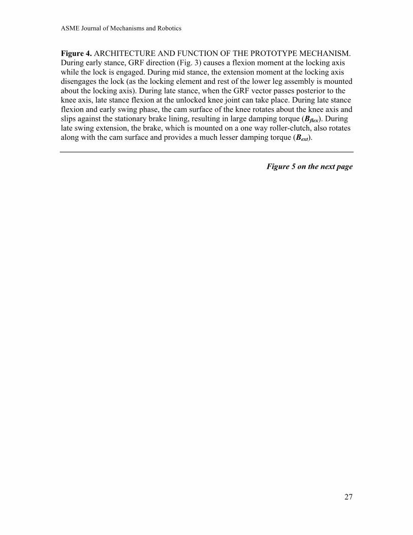
Figure 4. ARCHITECTURE AND FUNCTION OF THE PROTOTYPE MECHANISM. During early stance, GRF direction (Fig. 3) causes a flexion moment at the locking axis while the lock is engaged. During mid stance, the extension moment at the locking axis disengages the lock (as the locking element and rest of the lower leg assembly is mounted about the locking axis). During late stance, when the GRF vector passes posterior to the knee axis, late stance flexion at the unlocked knee joint can take place. During late stance flexion and early swing phase, the cam surface of the knee rotates about the knee axis and slips against the stationary brake lining, resulting in large damping torque (Bflex). During late swing extension, the brake, which is mounted on a one way roller-clutch, also rotates along with the cam surface and provides a much lesser damping torque (Bext).
Figure 5 on the next page
ASME Journal of Mechanisms and Robotics
28
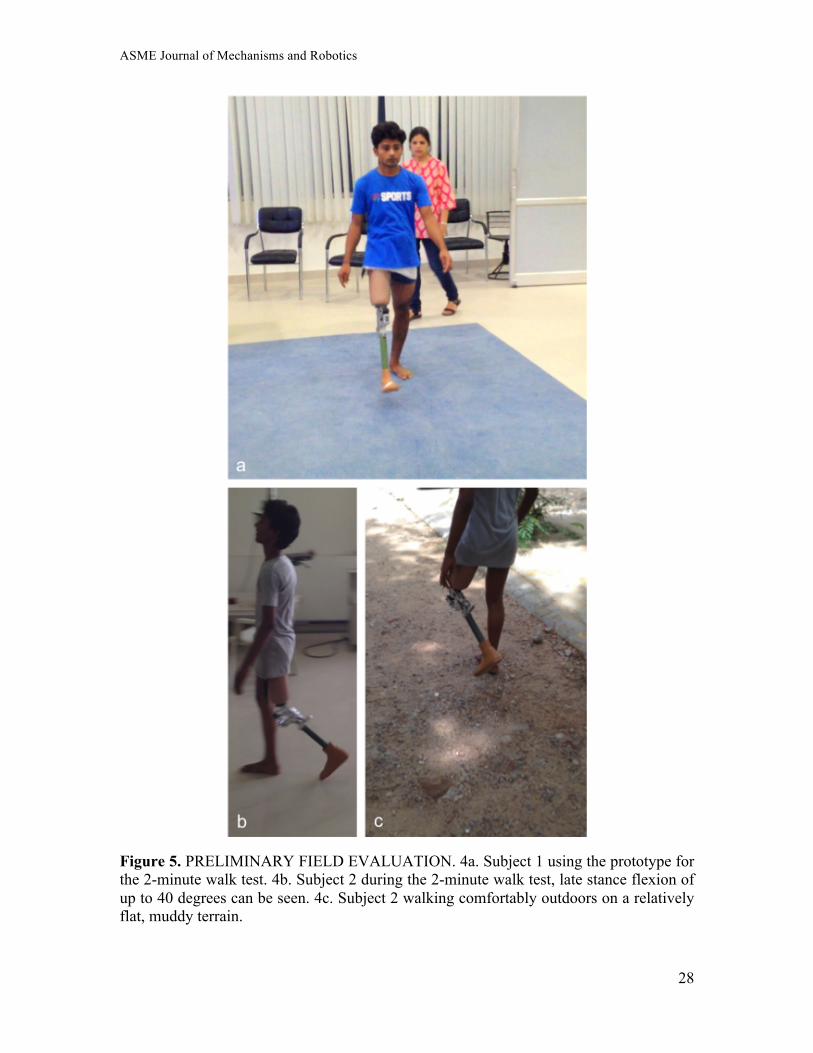
Figure 5. PRELIMINARY FIELD EVALUATION. 4a. Subject 1 using the prototype for the 2-minute walk test. 4b. Subject 2 during the 2-minute walk test, late stance flexion of up to 40 degrees can be seen. 4c. Subject 2 walking comfortably outdoors on a relatively flat, muddy terrain.

ASME Journal of Mechanisms and Robotics
29
Figure 6. The movement of the Center of Pressure on the foot during stance phase of gait (as a function of time) has been determined in past studies [27]. The magnitude and direction of the GRF vector is also known through the stance phase [27]. This provides complete information about the physical location of the GRF vector as a function of time during stance phase of gait. The positioning of the locking axis (shown in Fig. 4) is optimized in 2D space (the sagittal plane) to achieve the following: the GRF vector originating from the center of pressure is posterior to the locking axis during early stance, keeping the knee locked. During mid stance, the center of pressure advances, moving the GRF vector anterior to the knee and locking axis, releasing the latch. During late stance just before toe off, the latch remains disengaged (Fig. 4), as the GRF vector moves
ASME Journal of Mechanisms and Robotics
30
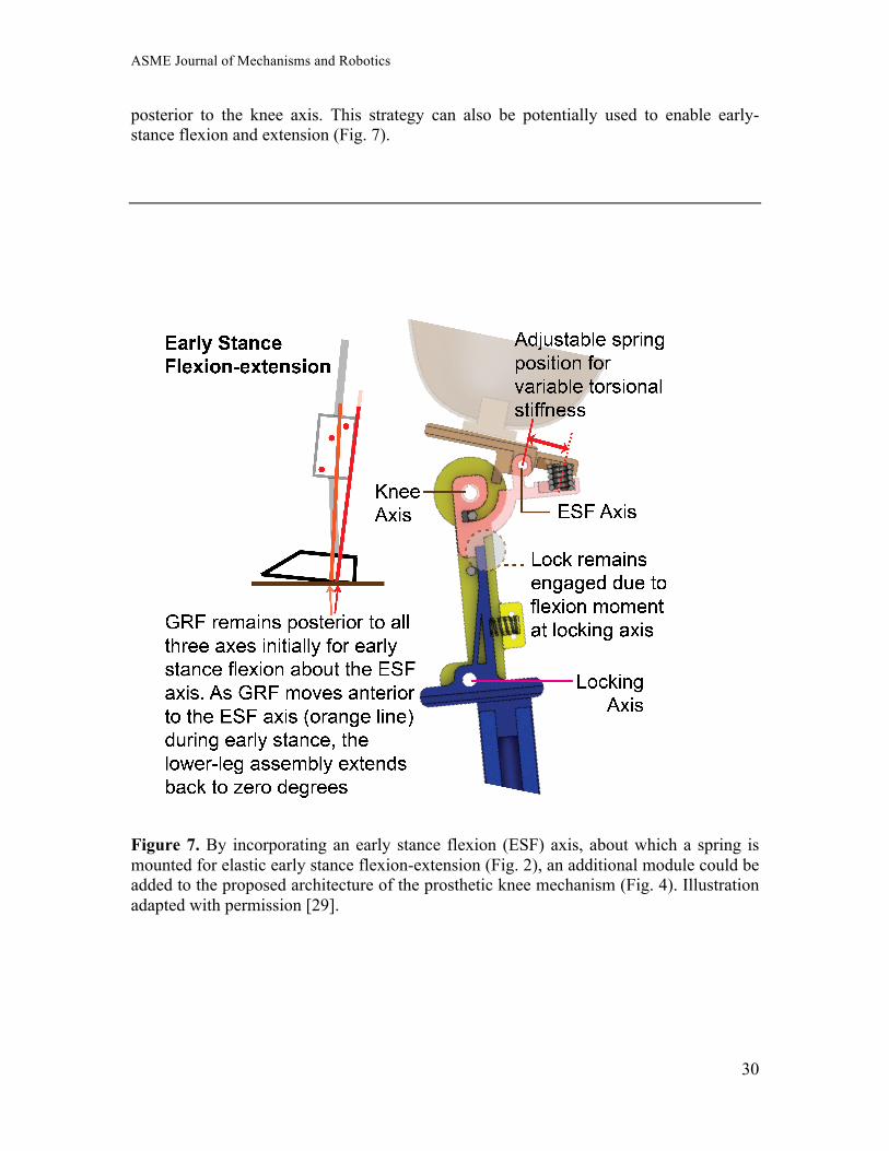
posterior to the knee axis. This strategy can also be potentially used to enable early-stance flexion and extension (Fig. 7).
Figure 7. By incorporating an early stance flexion (ESF) axis, about which a spring is mounted for elastic early stance flexion-extension (Fig. 2), an additional module could be added to the proposed architecture of the prosthetic knee mechanism (Fig. 4). Illustration adapted with permission [29].