
Design and Performance Evaluation of Different Feeding ... · for wireless microstrip patch antenna...
7
International Research Journal of Engineering and Technology (IRJET) e-ISSN: 2395 -0056 © 2016, IRJET | Impact Factor value: 4.45 | ISO 9001:2008 Certified Journal | Page 202 Design and Performance Evaluation of Different Feeding Technique for IMT Advanced (4G) Antenna Neeraj Kumari 1 , Amit Kumar 2 1 Assistant Professor, ECE Department, G.I.M.T (Karnal),Kurukshetra University, Kurukshetra 2 Assistant Professor, ECE Department, K.I.T.M (Karnal), Kurukshetra University, Kurukshetra [email protected] 1 , [email protected] 2 Abstract- This paper describes the designing of rectangular Microstrip patch antenna for all different feeding technique for wireless microstrip patch antenna i.e for IMT-Advanced (4G) applications. In this paper the antenna is resonating at 2.2 GHz frequency range which is desired frequency for IMT- Advanced (4G) range. The frequency range for 4G is vary from 1710 MHz to 2690 MHz. The proposed antenna is designed by using all four types of feeding techniques (Microstrip line feed, coaxial probe feed, proximity coupled feed and aperture coupled feed) are used. From the four feeding techniques, microstrip line and coaxial probe feeds are contacting schemes whereas proximity and aperture coupled feed are non- contacting schemes. Paper gives a better understanding of design parameters of an antenna and their effect on return loss, S-Parameters, smith chart, radiation pattern, bandwidth, VSWR and resonant frequency. Finally simulation is done using design software HFSS. Keywords- Rectangular microstrip patch antenna, S- Parameters, smith chart, radiation pattern, bandwidth, VSWR, resonant frequency, microstrip feed, coaxial probe feed, proximity coupled feed, aperture coupled feed, HFSS. I. INTRODUCTION Satellite communication and wireless communication has been develop rapidly in the past decades. Today world’s communication depends on wireless links. In the last few years, the development of WLAN represented one of the principal interests in the information and communication field. Thus, the current trend in commercial and government communication system has been develop low cost, minimal weight, low profile antennas that are capable of maintaining high performance over a large spectrum of frequencies. This technology trend has focused much effort into the design MPA. MPA are well suited for WLAN/WiMAX application system and having some disadvantage, like narrow bandwidth, low gain etc. Broad banding is the main problem, for solving this problem we proposed new structure for devices that require more than one frequency band of operation. Dual-band wireless phones have became popular recently because they allow using one phone in two networks that have different frequencies. Modern wireless communication system also requires low profile, light weight, high gain, ease of installation, high efficiency, simple in structure to assure reliability and mobility characteristics. Microstrip antennas satisfy such requirements. Research on microstrip antenna in 21st century aims at size reduction, increasing gain, wide bandwidth, multiple functionality and system level integration. Significant research work has been reported on increasing gain and bandwidth of microstrip antennas. Many techniques have been suggested for achieving wide bandwidth [4-5]. Main advantage of microstrip antenna includes low profile easy to fabricate (use etching and photolithography), easy to feed (proximity coupled, microstrip line, etc.) and easy to use in array of incorporate with other microstrip circuit elements [6]. In this paper four feeding techniques are compared for IMT- Advance (4G) band (1710 – 2690 MHz). II. FEEDING TECHNIQUES In its most basic form, a microstrip patch antenna consist of a radiating patch on one side of a dielectric substrate which has a ground plane on the other side as shown in figure 2.1. The patch is generally made of conducting material such as copper or gold and can take any possible shape. The radiating patch and the feed lines are usually photo etched on the dielectric substrate. Feeding Techniques are classified into two categories- contacting and non-contacting. The four most popular feed techniques used are the microstrip line, coaxial probe (both contacting schemes), aperture coupling and proximity coupling (both non-contacting schemes). A. Microstrip Line Feed Microstrip line feeding is a technique in which a conducting strip is connected directly to the edge of the microstrip patch as shown in figure 1. The width of conducting strip is smaller as compared to the patch. This type of feeding arrangement has the advantage that the feed and patch can be etched on the same substrate to provide a planar structure. However as the thickness of the dielectric substrate being used increases, surface waves and spurious feed radiation also increases, which hampers the bandwidth of the antenna. The feed radiation also leads to undesired cross polarized radiation. This method is advantageous due to its simple planar structure. Volume: 03 Issue: 10 | Oct -2016 www.irjet.net p-ISSN: 2395-0072
Transcript of Design and Performance Evaluation of Different Feeding ... · for wireless microstrip patch antenna...

International Research Journal of Engineering and Technology (IRJET) e-ISSN: 2395 -0056
© 2016, IRJET | Impact Factor value: 4.45 | ISO 9001:2008 Certified Journal | Page 202
Design and Performance Evaluation of Different Feeding Technique for IMT Advanced (4G) Antenna
Neeraj Kumari1, Amit Kumar2
1 Assistant Professor, ECE Department, G.I.M.T (Karnal),Kurukshetra University, Kurukshetra 2 Assistant Professor, ECE Department, K.I.T.M (Karnal), Kurukshetra University, Kurukshetra
[email protected], [email protected]
Abstract- This paper describes the designing of rectangular Microstrip patch antenna for all different feeding technique for wireless microstrip patch antenna i.e for IMT-Advanced (4G) applications. In this paper the antenna is resonating at 2.2 GHz frequency range which is desired frequency for IMT-Advanced (4G) range. The frequency range for 4G is vary from 1710 MHz to 2690 MHz. The proposed antenna is designed by using all four types of feeding techniques (Microstrip line feed, coaxial probe feed, proximity coupled feed and aperture coupled feed) are used. From the four feeding techniques, microstrip line and coaxial probe feeds are contacting schemes whereas proximity and aperture coupled feed are non-contacting schemes. Paper gives a better understanding of design parameters of an antenna and their effect on return loss, S-Parameters, smith chart, radiation pattern, bandwidth, VSWR and resonant frequency. Finally simulation is done using design software HFSS. Keywords- Rectangular microstrip patch antenna, S-Parameters, smith chart, radiation pattern, bandwidth, VSWR, resonant frequency, microstrip feed, coaxial probe feed, proximity coupled feed, aperture coupled feed, HFSS.
I. INTRODUCTION Satellite communication and wireless communication has been develop rapidly in the past decades. Today world’s communication depends on wireless links. In the last few years, the development of WLAN represented one of the principal interests in the information and communication field. Thus, the current trend in commercial and government communication system has been develop low cost, minimal weight, low profile antennas that are capable of maintaining high performance over a large spectrum of frequencies. This technology trend has focused much effort into the design MPA. MPA are well suited for WLAN/WiMAX application system and having some disadvantage, like narrow bandwidth, low gain etc. Broad banding is the main problem, for solving this problem we proposed new structure for devices that require more than one frequency band of operation. Dual-band wireless phones have became popular recently because they allow using one phone in two networks that have different frequencies. Modern wireless communication system also requires low profile, light weight, high gain, ease of installation, high efficiency, simple
in structure to assure reliability and mobility characteristics. Microstrip antennas satisfy such requirements. Research on microstrip antenna in 21st century aims at size reduction, increasing gain, wide bandwidth, multiple functionality and system level integration. Significant research work has been reported on increasing gain and bandwidth of microstrip antennas. Many techniques have been suggested for achieving wide bandwidth [4-5]. Main advantage of microstrip antenna includes low profile easy to fabricate (use etching and photolithography), easy to feed (proximity coupled, microstrip line, etc.) and easy to use in array of incorporate with other microstrip circuit elements [6]. In this paper four feeding techniques are compared for IMT-Advance (4G) band (1710 – 2690 MHz).
II. FEEDING TECHNIQUES
In its most basic form, a microstrip patch antenna consist of a radiating patch on one side of a dielectric substrate which has a ground plane on the other side as shown in figure 2.1. The patch is generally made of conducting material such as copper or gold and can take any possible shape. The radiating patch and the feed lines are usually photo etched on the dielectric substrate. Feeding Techniques are classified into two categories- contacting and non-contacting. The four most popular feed techniques used are the microstrip line, coaxial probe (both contacting schemes), aperture coupling and proximity coupling (both non-contacting schemes).
A. Microstrip Line Feed Microstrip line feeding is a technique in which a conducting strip is connected directly to the edge of the microstrip patch as shown in figure 1. The width of conducting strip is smaller as compared to the patch. This type of feeding arrangement has the advantage that the feed and patch can be etched on the same substrate to provide a planar structure. However as the thickness of the dielectric substrate being used increases, surface waves and spurious feed radiation also increases, which hampers the bandwidth of the antenna. The feed radiation also leads to undesired cross polarized radiation. This method is advantageous due to its simple planar structure.
Volume: 03 Issue: 10 | Oct -2016 www.irjet.net p-ISSN: 2395-0072

International Research Journal of Engineering and Technology (IRJET) e-ISSN: 2395 -0056
© 2016, IRJET | Impact Factor value: 4.45 | ISO 9001:2008 Certified Journal | Page 203
Figure 1 Microstrip Line Feed
B. Coaxial Probe Feed The Coaxial feed or probe feed is a very common technique used for feeding Microstrip patch antennas. The inner conductor of the coaxial connector extends through the dielectric and is soldered to the radiating patch, while the outer conductor is connected to the ground plane. The main advantage of this type of feeding scheme is that the feed can be placed at any desired location inside the patch in order to match with its input impedance. However, its major drawback is that it provides narrow bandwidth and is difficult to model since a hole has to be drilled in the substrate and the connector protrudes outside the ground plane, thus not making it completely planar for thick substrates. Also, for thicker substrates, the increased probe length makes the input impedance more inductive, leading to matching problems. It is seen above that for a thick dielectric substrate, which provides broad bandwidth, the microstrip line feed and the coaxial feed suffer from numerous disadvantages. So to reduce these types of disadvantages, we will study non-contactingschemes.
Figure 2 Coaxial probe Feed
C. Proximity coupled Feed This method uses electromagnetic coupling between the feed line and the radiating patches, printed on separate substrates [7]. Two dielectric substrates are used such that the radiating patch is on top of the upper substrate and feed line is between the two substrates. The advantage of this coupling is that it yields the largest bandwidth compared to other coupling methods, it is somewhat easy to model and has low spurious radiation. This feeding method also provides choices between two different dielectric media, one for the feed line and one for the patch to optimize the individual performances. Matching can be achieved by controlling the width-to-line ratio of the patch and length of the feed line. The major disadvantage of this feeding scheme is that it is difficult to fabricate because of the two dielectric layers which need proper alignment. Also, the overall thickness of the antenna also increases.
Volume: 03 Issue: 10 | Oct -2016 www.irjet.net p-ISSN: 2395-0072
International Research Journal of Engineering and Technology (IRJET) e-ISSN: 2395 -0056
© 2016, IRJET | Impact Factor value: 4.45 | ISO 9001:2008 Certified Journal | Page 204
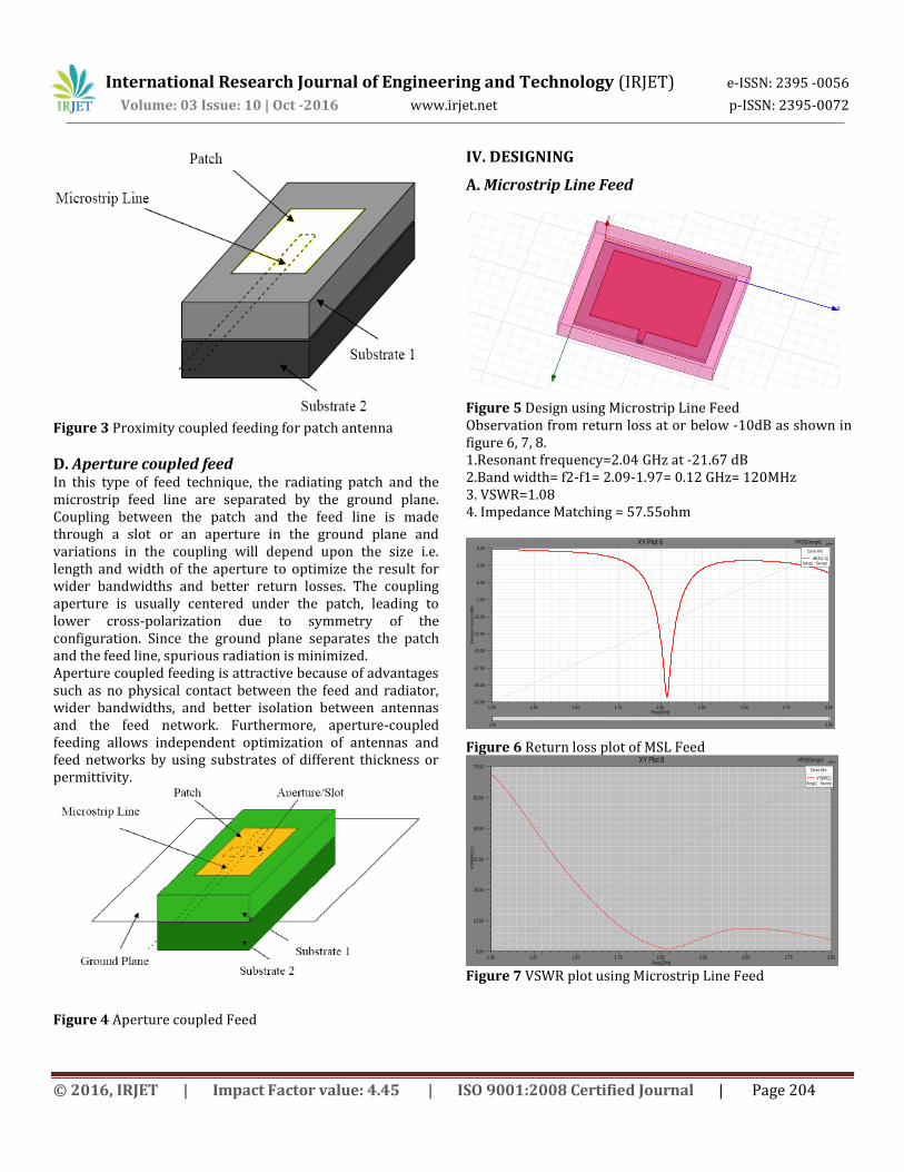
Figure 3 Proximity coupled feeding for patch antenna
D. Aperture coupled feed In this type of feed technique, the radiating patch and the microstrip feed line are separated by the ground plane. Coupling between the patch and the feed line is made through a slot or an aperture in the ground plane and variations in the coupling will depend upon the size i.e. length and width of the aperture to optimize the result for wider bandwidths and better return losses. The coupling aperture is usually centered under the patch, leading to lower cross-polarization due to symmetry of the configuration. Since the ground plane separates the patch and the feed line, spurious radiation is minimized. Aperture coupled feeding is attractive because of advantages such as no physical contact between the feed and radiator, wider bandwidths, and better isolation between antennas and the feed network. Furthermore, aperture-coupled feeding allows independent optimization of antennas and feed networks by using substrates of different thickness or permittivity.
Figure 4 Aperture coupled Feed
IV. DESIGNING
A. Microstrip Line Feed
Figure 5 Design using Microstrip Line Feed Observation from return loss at or below -10dB as shown in figure 6, 7, 8. 1.Resonant frequency=2.04 GHz at -21.67 dB 2.Band width= f2-f1= 2.09-1.97= 0.12 GHz= 120MHz 3. VSWR=1.08 4. Impedance Matching = 57.55ohm
Figure 6 Return loss plot of MSL Feed
Figure 7 VSWR plot using Microstrip Line Feed
1.00 1.25 1.50 1.75 2.00 2.25 2.50 2.75 3.00Freq [GHz]
-22.50
-20.00
-17.50
-15.00
-12.50
-10.00
-7.50
-5.00
-2.50
0.00
Re
turn
Lo
ss (
dB
)
1.00 3.00
HFSSDesign1XY Plot 6 ANSOFT
Curve Info
dB(S(1,1))Setup1 : Sw eep
1.00 1.25 1.50 1.75 2.00 2.25 2.50 2.75 3.00Freq [GHz]
0.00
12.50
25.00
37.50
50.00
62.50
75.00
VS
WR
(1)
HFSSDesign1XY Plot 8 ANSOFT
Curve Info
VSWR(1)Setup1 : Sw eep
Volume: 03 Issue: 10 | Oct -2016 www.irjet.net p-ISSN: 2395-0072

International Research Journal of Engineering and Technology (IRJET) e-ISSN: 2395 -0056
© 2016, IRJET | Impact Factor value: 4.45 | ISO 9001:2008 Certified Journal | Page 205
Figure 8 Smith chart plot using Microstrip Line Feed
B. Coaxial Probe Feed
Figure 9 Design using Coaxial Feed Observation from return loss at or below -10dB as shown in figure 10, 11, 12. 1. Resonant frequency=2.1 GHz at -19.77dB 2. Band width= f2-f1= 2.13-2.03= 0.10GHz = 100MHz 3. VSWR= 1.21 4. Impedance Matching = 59.05 ohm
Figure 10 Return loss plot using Coaxial Feed
Figure 11 VSWR plot using Coaxial Feed
Figure 12 Smith Chart plot using Coaxial Feed
C. Proximity coupled Feed
Figure 13 Design using Proximity Coupled Feed Observation from return loss at or below -10dB as shown in figure 14, 15, 16. 1. Resonant frequency=2.19 GHz at -17.90 dB 2. Band width= f2-f1= 2.26-2.13=0.13GHz=130MHz 3. VSWR= 1.08 4. Impedance Matching = 48.80 ohm
5.002.001.000.500.200.00
5.00
-5.00
2.00
-2.00
1.00
-1.00
0.50
-0.50
0.20
-0.20
0.000
10
20
30
40
50
60
708090100
110
120
130
140
150
160
170
180
-170
-160
-150
-140
-130
-120
-110-100 -90 -80
-70
-60
-50
-40
-30
-20
-10
HFSSDesign1Smith Chart 1 ANSOFT
Curve Info
S(1,1)Setup1 : Sw eep
1.80 1.90 2.00 2.10 2.20 2.30 2.40 2.50 2.60Freq [GHz]
-20.00
-18.00
-16.00
-14.00
-12.00
-10.00
-8.00
-6.00
-4.00
-2.00
Re
turn
Lo
ss (
dB
)
1.80 2.60
S Parameter HFSSDesign1XY Plot 15 ANSOFT
Curve Info
dB(S(1,1))Setup1 : Sw eep
1.80 1.90 2.00 2.10 2.20 2.30 2.40 2.50 2.60Freq [GHz]
1.00
2.00
3.00
4.00
5.00
6.00
7.00
8.00
9.00
VS
WR
HFSSDesign1XY Plot 16 ANSOFT
Curve Info
VSWR(1)Setup1 : Sw eep
5.002.001.000.500.200.00
5.00
-5.00
2.00
-2.00
1.00
-1.00
0.50
-0.50
0.20
-0.20
0.000
10
20
30
40
50
60
708090100
110
120
130
140
150
160
170
180
-170
-160
-150
-140
-130
-120
-110-100 -90 -80
-70
-60
-50
-40
-30
-20
-10
HFSSDesign1Smith Chart 1 ANSOFT
Curve Info
S(1,1)Setup1 : Sw eep
Volume: 03 Issue: 10 | Oct -2016 www.irjet.net p-ISSN: 2395-0072

International Research Journal of Engineering and Technology (IRJET) e-ISSN: 2395 -0056
© 2016, IRJET | Impact Factor value: 4.45 | ISO 9001:2008 Certified Journal | Page 206
Figure 14 Return loss Proximity Coupled Feed
Figure 15 VSWR Plot Proximity Coupled Feed
Figure 16 Smith Chart plot using Proximity Coupled Feed
D. Aperture coupled feed
Figure 17 Design using Aperture Coupled Feed
Observation from return loss at or below -10dB as shown in figure 18, 19, 20. 1. Resonant frequency=2.27 GHz at -20.06dB 2. Band width= f2-f1= 2.33-2.21=0.12GHz=120MHz 3. VSWR = 1.02 4. Impedance Matching = 51.78 ohm
Figure 18 Return Loss plot using Aperture Coupled Feed
Figure 19 VSWR plot using Aperture Coupled Feed
1.00 1.25 1.50 1.75 2.00 2.25 2.50 2.75 3.00Freq [GHz]
-30.00
-25.00
-20.00
-15.00
-10.00
-5.00
0.00
Re
tun
Lo
ss (
dB
)
HFSSDesign1XY Plot 18 ANSOFT
Curve Info
dB(S(1,1))Setup1 : Sw eep
1.00 1.25 1.50 1.75 2.00 2.25 2.50 2.75 3.00Freq [GHz]
0.00
12.50
25.00
37.50
50.00
62.50
75.00
VS
WR
HFSSDesign1XY Plot 19 ANSOFT
Curve Info
VSWR(1)Setup1 : Sw eep
5.002.001.000.500.200.00
5.00
-5.00
2.00
-2.00
1.00
-1.00
0.50
-0.50
0.20
-0.20
0.000
10
20
30
40
50
60
708090100
110
120
130
140
150
160
170
180
-170
-160
-150
-140
-130
-120
-110-100 -90 -80
-70
-60
-50
-40
-30
-20
-10
HFSSDesign1Smith Chart 1 ANSOFT
Curve Info
S(1,1)Setup1 : Sw eep
1.00 1.50 2.00 2.50 3.00 3.50Freq [GHz]
-22.50
-20.00
-17.50
-15.00
-12.50
-10.00
-7.50
-5.00
-2.50
0.00
Re
turn
Lo
ss (
dB
)
HFSSDesign1XY Plot 9 ANSOFT
Curve Info
dB(S(1,1))Setup1 : Sw eep
1.00 1.50 2.00 2.50 3.00 3.50Freq [GHz]
0.00
10.00
20.00
30.00
40.00
50.00
60.00
70.00
VS
WR
HFSSDesign1XY Plot 10 ANSOFT
Curve Info
VSWR(1)Setup1 : Sw eep
Volume: 03 Issue: 10 | Oct -2016 www.irjet.net p-ISSN: 2395-0072

International Research Journal of Engineering and Technology (IRJET) e-ISSN: 2395 -0056
© 2016, IRJET | Impact Factor value: 4.45 | ISO 9001:2008 Certified Journal | Page 207
Figure 20 Smith plot using Aperture Coupled Feed Table I Comparison of Various Feeding Techniques Characteristics
MSL
Coaxial
Proximity
Aperture
Impedance(ohm)
59.05 57.55 48.80 51.78
Bandwidth (MHz)
120 100 130 120
Return Loss (db)
-21.67 -19.77 -27.90 -20.06
VSWR 1.08 1.21 1.08 1.02 Patch Size(mm)
32.17×41.49
32.17×41.49
34.17×41.49
32.17×41.49
V. CONCLUSION
The rectangular microstrip patch antenna of same dimensions using all four different feeds has been designed and simulated using HFSS V13 software. A comparison is made between feeding techniques in terms of bandwidth, return loss, VSWR and patch size and smith chart. So, we can see that selection of the feeding technique for a microstrip patch antenna is an important decision because it affects the bandwidth and other parameters also. A microstrip patch antenna excited by different excitation techniques gives different bandwidth, different gain, different efficiency etc. The performance properties are analyzed for the optimized dimensions and the proposed antenna works well at the required (1710-2690) MHz IMT-Advance (4G) frequency band. The maximum bandwidth can be achieved by proximity coupling. Aperture coupling gives the best impedance matching and radiation efficiency. Coaxial feeding technique gives the least bandwidth. We can also conclude that by changing the feed point where matching is perfect, the high return loss can be achieved at the resonant frequency. Various microstrip patch antennas with each
different feeding technique and with various antenna parameters are presented.
REFERENCES [1] Ramesh Garg, Prakash Bhartie, Inder Bahl, Apisak Ittipiboon, “Microstrip Antenna Design Handbook”, 2001 pp. 1-68, 253-316 Artech House Inc. Norwood. [2].Y.-L. Ban, J.-H. Chen, S. C. Sun, J. L.-W. Li, and J.-H. Guo. “Printed Wideband Antenna with Capacitor-loaded Inductive Strip for LTE/GSM/UMTS/W WAN Wireless USB dongle application” Progress In Electromagnetic Research Vol. 128, 313-329, 2012. [3].Luis Inclan-Sanchez, Jose-Luis Vazques-Roy “Proximity Coupled Microstrip Patch Antenna With Reduced Harmonic Radiation”in 2009. [4].R. Saluja, A.L.Krishna, P.K. Khanna “Analysis of Bluetooth Patch Antenna with Different Feeding Techniques using Simulation and Optimization” in 2008. [5].Richard Q. Lee “Coplanar Waveguide Aperture-Coupled Microstrip Patch Antenna”in1992 [6] A wideband and dual polarization base station antenna for IMT-Advanced system. IEEE Cross Strait Quad – Regional Radio Science and Wireless Technology Conference (CSQRWC), 2011. [7] http://en.wikipedia.org/wiki/IMT-Advanced [8] C.A. Balanis, “Antenna Theory (Analysis and Design)”, Second Edition, John Wiley & Sons. [9] Jihak Jung, Wooyoung Choi, and Jaehoon Choi, ”Small Wideband Microstrip-fed Monopole Antenna”, IEEE Microwave and Wireless Components Letters, vol. 15, no.10, October 2005, pp.703-705. [10] Mohammed Al-Husseini, Youssef Tawk, Ali El-Hajj, and Karim Y. Kabalan,” A Low-Cost Microstrip Antenna for 3G/WLAN/WiMAX and UWB Applications”, International Conference on Advances in Computational Tools for Engineering Applications, ACTEA '09, july 2009, pp. 68-70. [11]C Wu, k. L. Wu, Z Bi, J. Litva, “Modelling of coaxial-fed microstrip patch antenna By finite difference time domain method”, Electronics Letters 12th September 1991, Vol. 27, issue 19, pp. 1691-1692. [12] H.W. Lai, P. Li and K.M. Luk,” Wideband small patch antenna”, Electronics Letters 17th April 2003, Vol. 39 issue 8, pp 641-642. [13] W. S. Chen, “Single feed Dual Frequency Rectangular Microstrip Antenna with Square Slot”, Electronics Letter 1998, vol. 34 issue 3, pp. 231-232. [14] Jing Liang and H.Y. David Yang,” Analysis of a Proximity Coupled Patch Antenna on a Metalized Substrate” Antennas and Propagation Society International Symposium, IEEE, July 2006, pp. 2287-2290.
5.002.001.000.500.200.00
5.00
-5.00
2.00
-2.00
1.00
-1.00
0.50
-0.50
0.20
-0.20
0.000
10
20
30
40
50
60
708090100
110
120
130
140
150
160
170
180
-170
-160
-150
-140
-130
-120
-110-100 -90 -80
-70
-60
-50
-40
-30
-20
-10
HFSSDesign1Smith Chart 1 ANSOFT
Curve Info
S(1,1)Setup1 : Sw eep
Volume: 03 Issue: 10 | Oct -2016 www.irjet.net p-ISSN: 2395-0072

International Research Journal of Engineering and Technology (IRJET) e-ISSN: 2395 -0056
© 2016, IRJET | Impact Factor value: 4.45 | ISO 9001:2008 Certified Journal | Page 208
BIOGRAPHIES
Ms. Neeraj Kumari is an Assistant Professor in ECE Department at Galaxy Institute of Technology and Management, Bhaini Kalan, Karnal, Haryana.
Mr. Amit Kumar Mehla is an Assistant Professor in ECE Department at Karnal Institute of Technology and Management, Karnal, Haryana.
Volume: 03 Issue: 10 | Oct -2016 www.irjet.net p-ISSN: 2395-0072