Design and Performance Evaluation of a Miniature Integrated Single Stage Centrifugal Compressor and...
47
Design and Performance Evaluation of a Miniature Integrated Single Stage Centrifugal Compressor and Permanent Magnet Synchronous Motor Presented by Dipjyoti Acharya M.S.M.E Thesis Defense May 30, 2006, 11: 00 Dept. of Mechanical, Materials and Aerospace Engineering University of Central Florida, Orlando
-
Upload
anderson-maiden -
Category
Documents
-
view
221 -
download
4
Transcript of Design and Performance Evaluation of a Miniature Integrated Single Stage Centrifugal Compressor and...
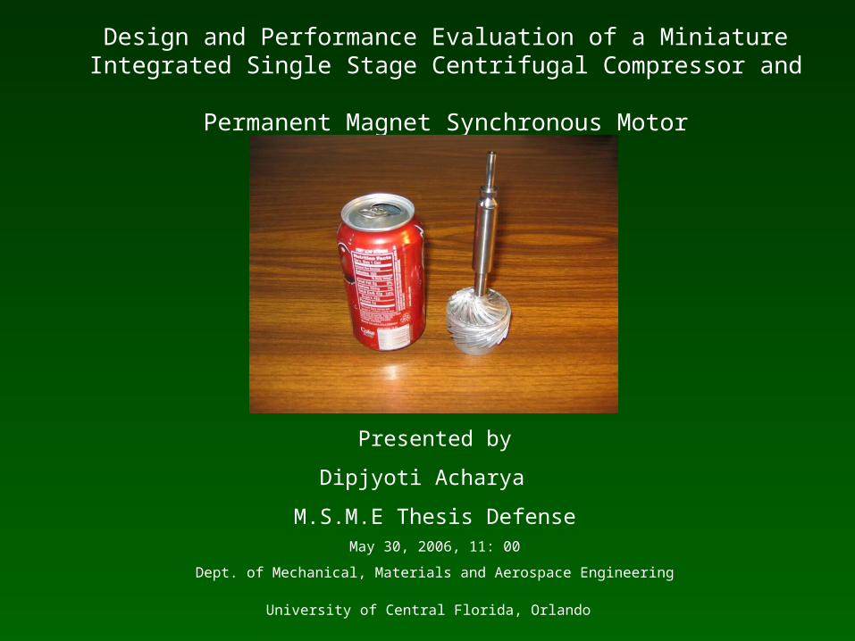
Design and Performance Evaluation of a Miniature Integrated Single Stage Centrifugal Compressor and
Permanent Magnet Synchronous Motor
Presented by
Dipjyoti Acharya
M.S.M.E Thesis DefenseMay 30, 2006, 11: 00
Dept. of Mechanical, Materials and Aerospace Engineering
University of Central Florida, Orlando
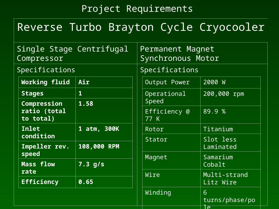
Project Requirements
Reverse Turbo Brayton Cycle Cryocooler
Single Stage Centrifugal Compressor Permanent Magnet Synchronous Motor
Specifications Specifications
Working fluid Air
Stages 1
Compression ratio (total to total)
1.58
Inlet condition 1 atm, 300K
Impeller rev. speed 108,000 RPM
Mass flow rate 7.3 g/s
Efficiency 0.65
Output Power 2000 W
Operational Speed 200,000 rpm
Efficiency @ 77 K 89.9 %
Rotor Titanium
Stator Slot less Laminated
Magnet Samarium Cobalt
Wire Multi-strand Litz Wire
Winding 6 turns/phase/pole
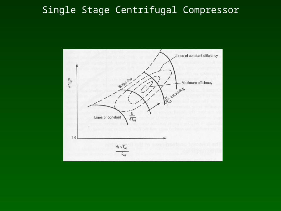
Single Stage Centrifugal Compressor
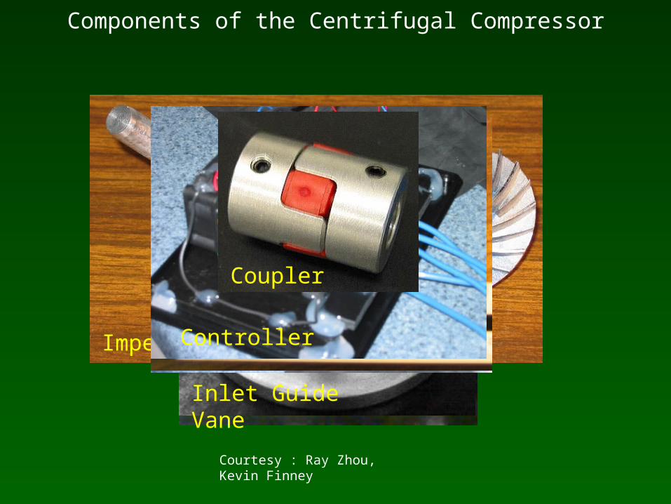
Components of the Centrifugal Compressor
Impeller
DiffuserInlet Guide Vane
Top plateCollectorKoford Electric MotorController
Coupler
Courtesy : Ray Zhou, Kevin Finney
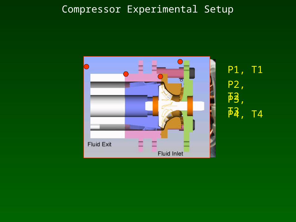
Compressor Experimental Setup
P1, T1
P2, T2
P3, T3
P4, T4
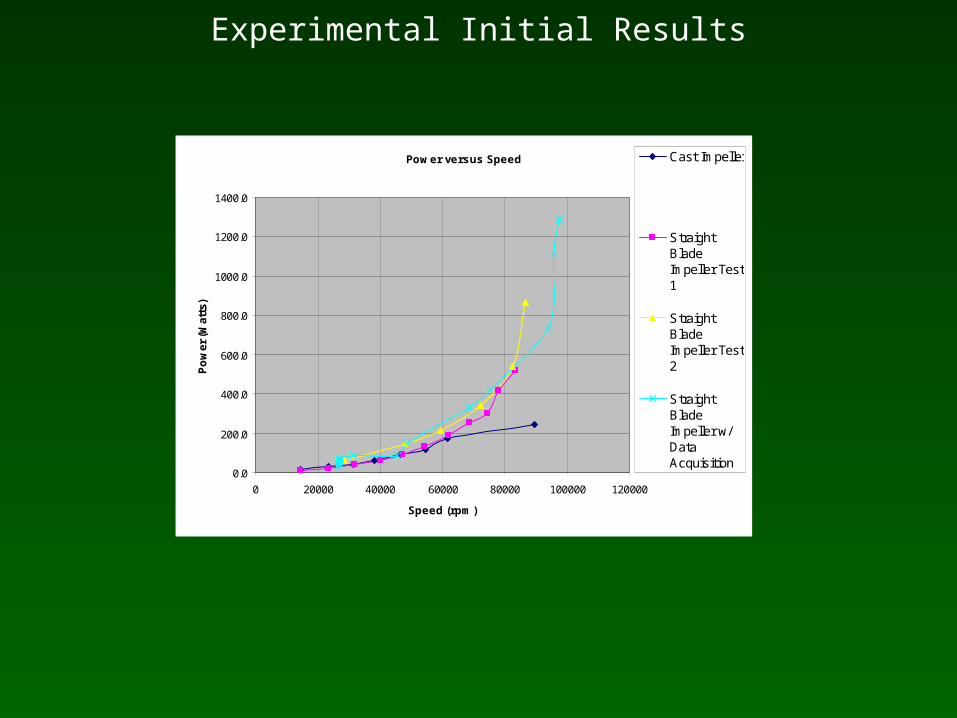
Experimental Initial Results
Power versus Speed
0.0
200.0
400.0
600.0
800.0
1000.0
1200.0
1400.0
0 20000 40000 60000 80000 100000 120000
Speed (rpm)
Po
wer
(W
atts
)
Cast Impeller
StraightBladeImpeller Test1
StraightBladeImpeller Test2
StraightBladeImpeller w/DataAcquisition
Issues to be resolved
• Resolve misalignment issues• Design of new coupler to handle high speeds• Design a new electric motor to handle the power required
by compressor

Problems with Rimitec Coupler
• Servo-insert coupling allowed a restricted amount of misalignment
• Elastic material in the middle began to plastically deform
• Stainless steel retaining ring was slip fit
• Coupler more rigid and prevented it from handling any misalignment
Disc couplings style –WM Berg Coupler
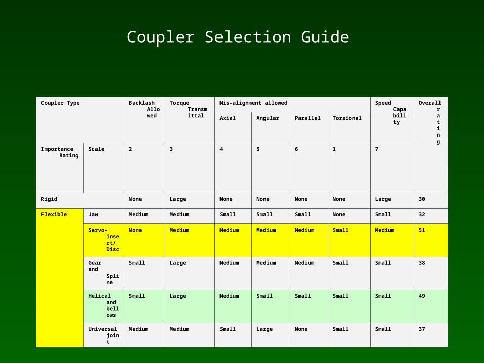
Coupler Selection Guide
Coupler Type Backlash Allowed
Torque Transmittal
Mis-alignment allowed Speed Capability
Overall rating
Axial Angular Parallel Torsional
Importance Rating
Scale 2 3 4 5 6 1 7
Rigid None Large None None None None Large 30
Flexible Jaw Medium Medium Small Small Small None Small 32
Servo-insert/ Disc
None Medium Medium Medium Medium Small Medium 51
Gear and Spline
Small Large Medium Medium Medium Small Small 38
Helical and bellows
Small Large Medium Small Small Small Small 49
Universal joint
Medium Medium Small Large None Small Small 37
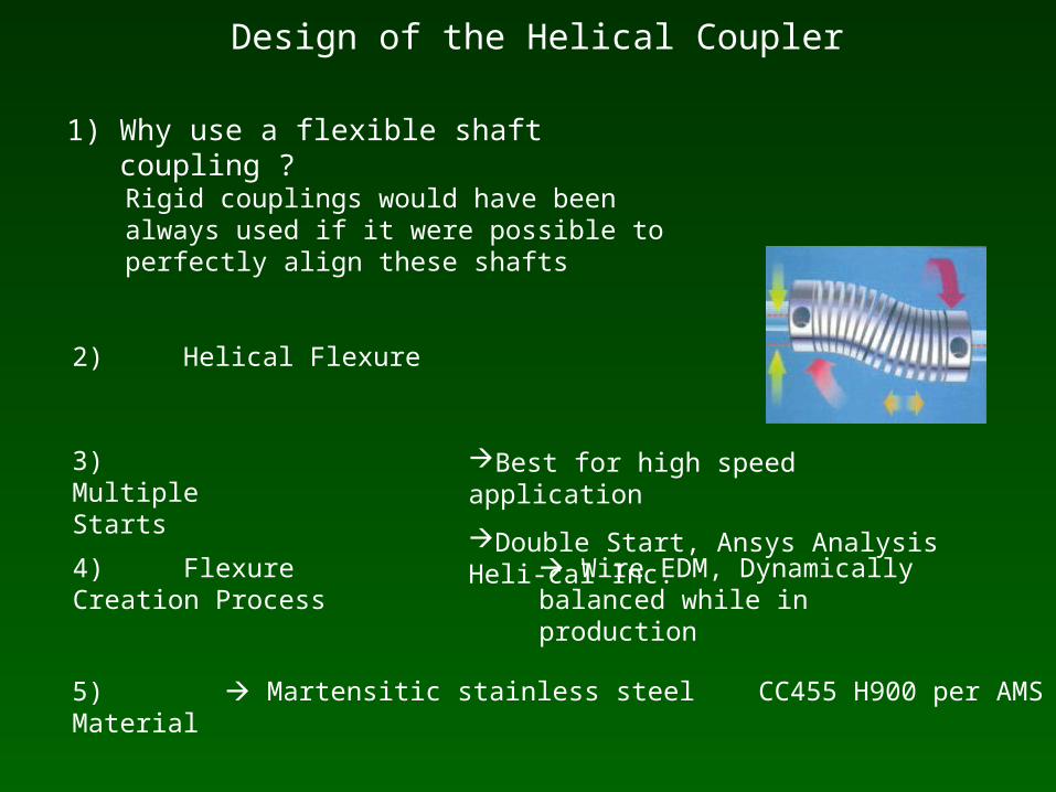
Design of the Helical Coupler
1) Why use a flexible shaft coupling ?
2) Helical Flexure
3) Multiple Starts
4) Flexure Creation Process
5) Material Martensitic stainless steel CC455 H900 per AMS 5617
Wire EDM, Dynamically balanced while in production
Best for high speed application
Double Start, Ansys Analysis Heli-cal Inc.
Rigid couplings would have been always used if it were possible to perfectly align these shafts
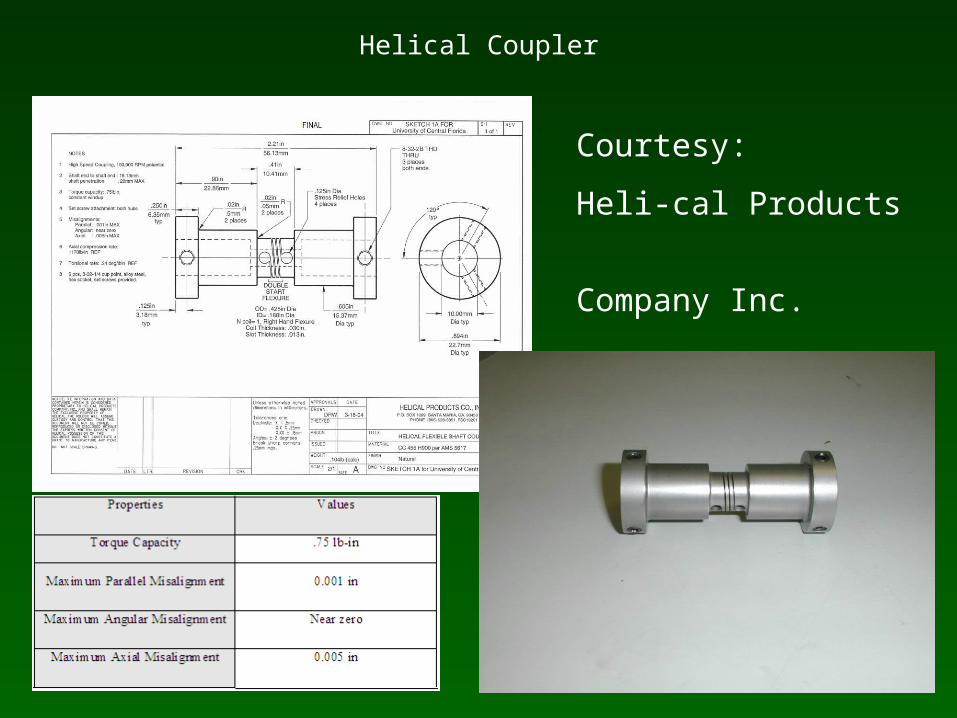
Helical Coupler
Courtesy:
Heli-cal Products
Company Inc.
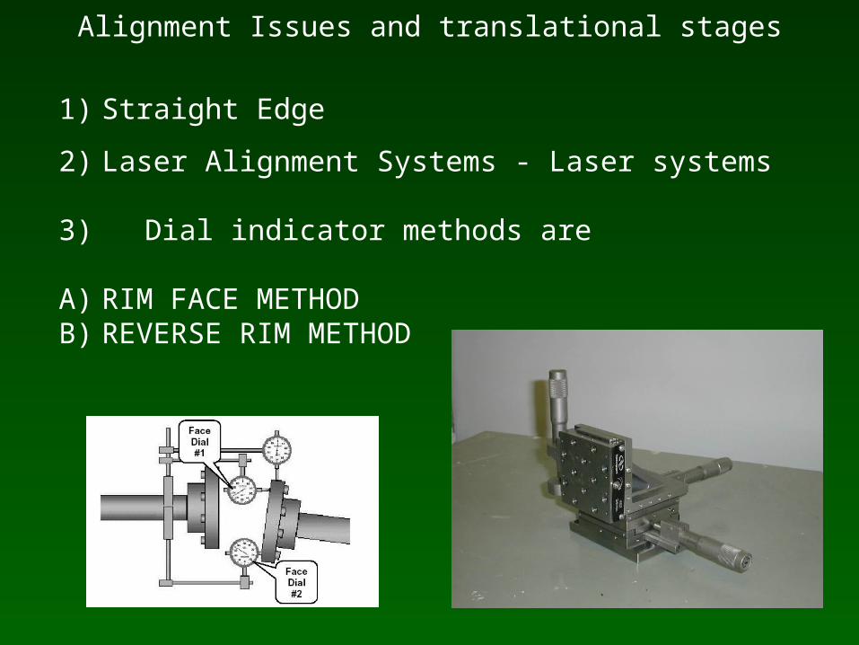
Alignment Issues and translational stages
1) Straight Edge
2) Laser Alignment Systems - Laser systems
3) Dial indicator methods are
A) RIM FACE METHODB) REVERSE RIM METHOD
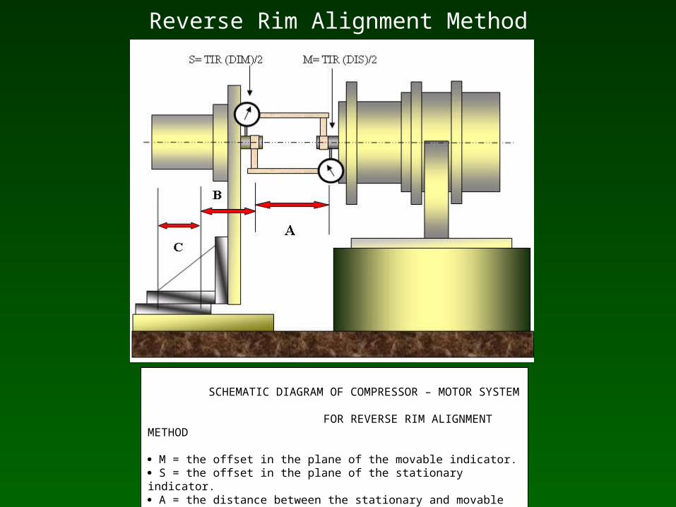
Reverse Rim Alignment Method
SCHEMATIC DIAGRAM OF COMPRESSOR – MOTOR SYSTEM FOR REVERSE RIM ALIGNMENT METHOD
M = the offset in the plane of the movable indicator. S = the offset in the plane of the stationary indicator. A = the distance between the stationary and movable dial indicator plungers. B = the distance from the movable dial indicator plunger to the movable machine’s front feet bolt center. C= the distance between the movable machines’ front and rear feet bolt centers.
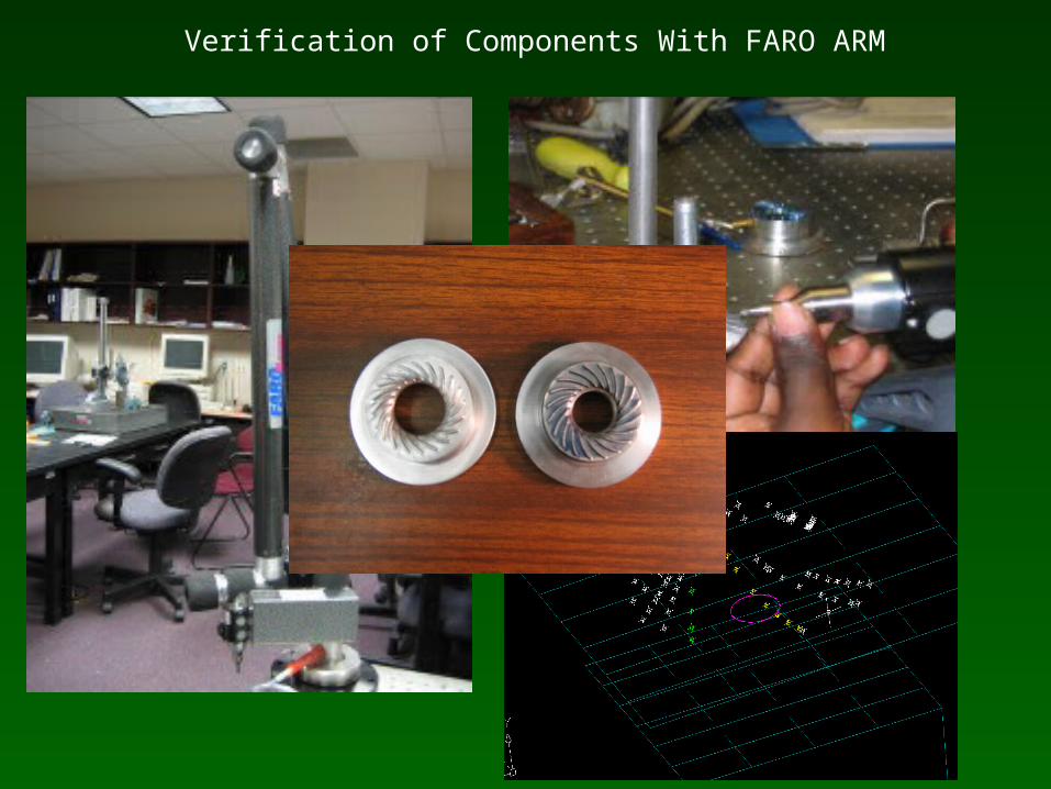
Verification of Components With FARO ARM
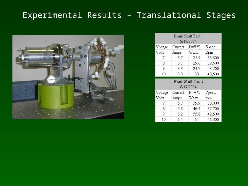
Experimental Results – Translational Stages
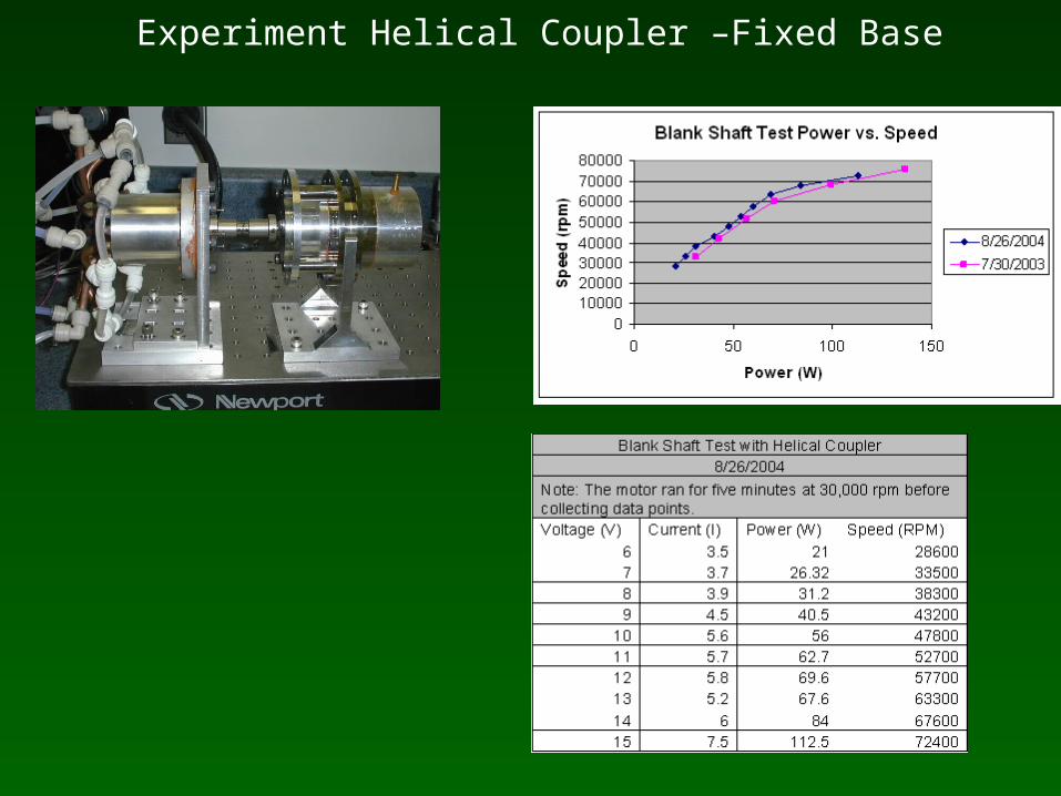
Experiment Helical Coupler –Fixed Base
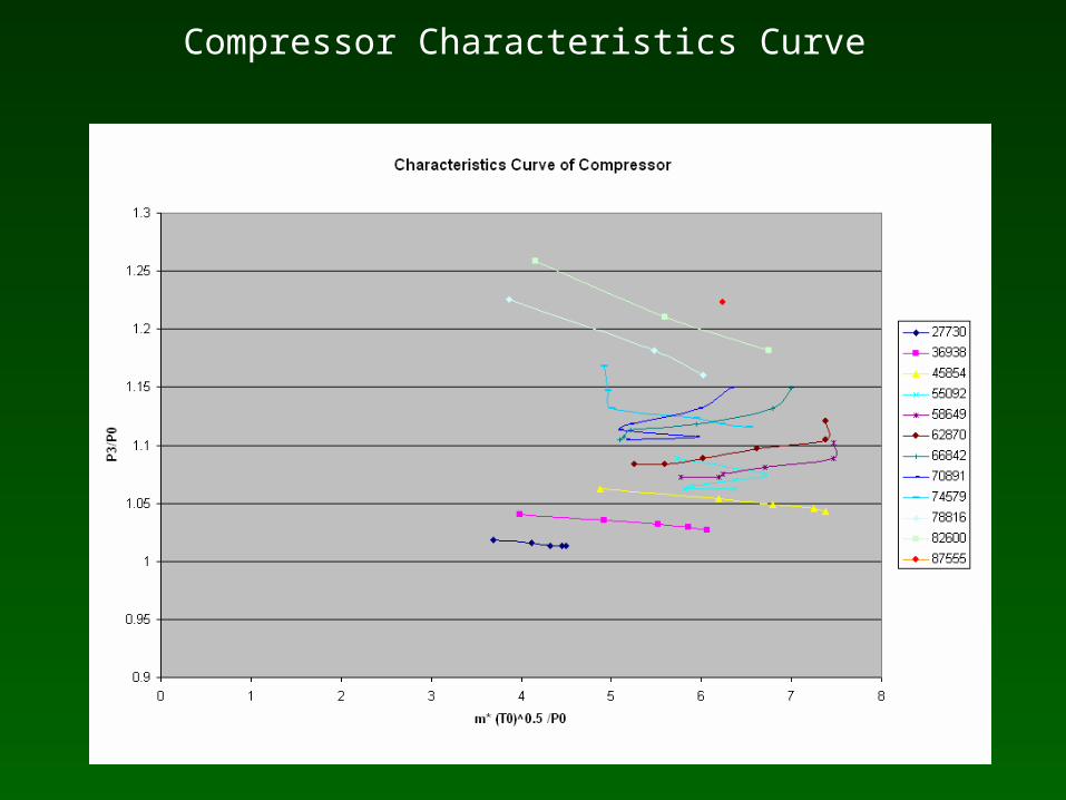
Compressor Characteristics Curve
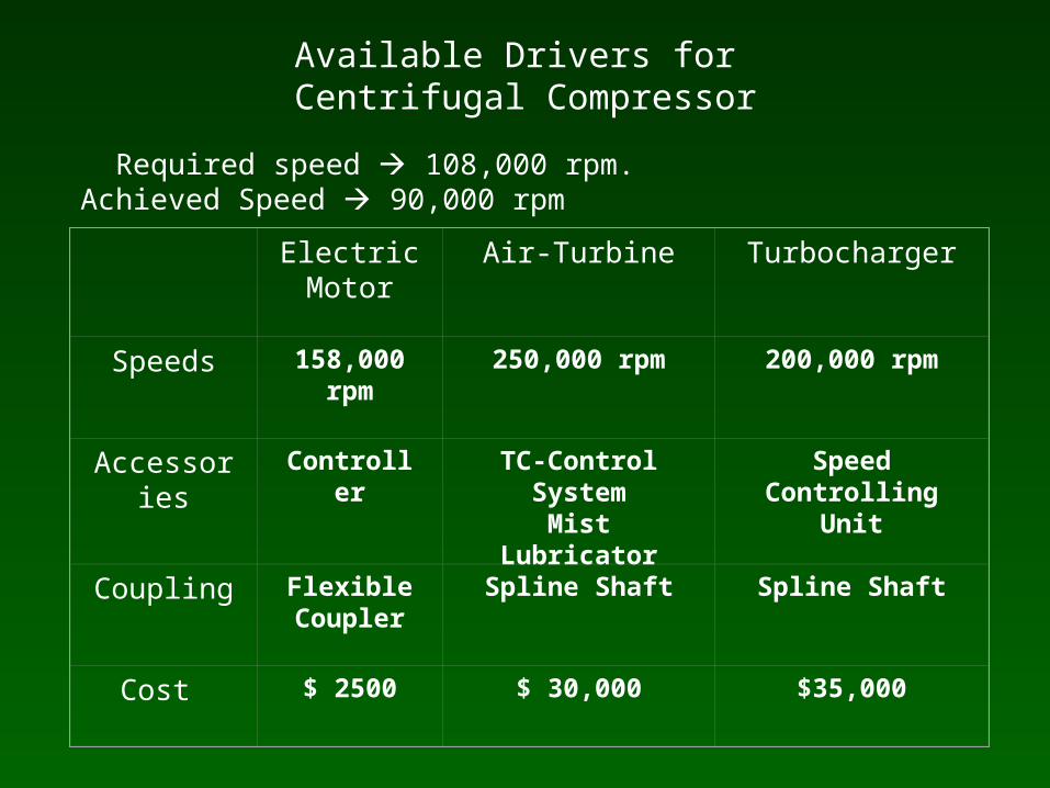
Available Drivers for Centrifugal Compressor
Required speed 108,000 rpm. Achieved Speed 90,000 rpm
Electric Motor
Air-Turbine Turbocharger
Speeds 158,000 rpm 250,000 rpm 200,000 rpm
Accessories Controller TC-Control SystemMist Lubricator
Speed Controlling Unit
Coupling Flexible Coupler
Spline Shaft Spline Shaft
Cost $ 2500 $ 30,000 $35,000

Design of Permanent Magnet Synchronous Motor
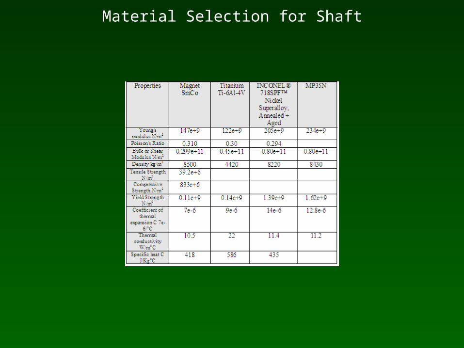
Material Selection for Shaft
Shear Stress Analysis
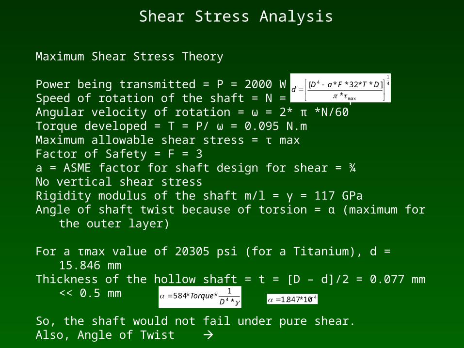
Maximum Shear Stress Theory
Power being transmitted = P = 2000 WSpeed of rotation of the shaft = N = 200000 rpmAngular velocity of rotation = ω = 2* π *N/60Torque developed = T = P/ ω = 0.095 N.mMaximum allowable shear stress = τ maxFactor of Safety = F = 3a = ASME factor for shaft design for shear = ¾No vertical shear stressRigidity modulus of the shaft m/l = γ = 117 GPaAngle of shaft twist because of torsion = α (maximum for the outer layer)
For a τmax value of 20305 psi (for a Titanium), d = 15.846 mmThickness of the hollow shaft = t = [D – d]/2 = 0.077 mm << 0.5 mm
So, the shaft would not fail under pure shear.Also, Angle of Twist
4
1
max
4
*
]**32**[
DTFaD
d
*
1**584
4DTorque 410*847.1

Bending Stress
The values considered for the bending stress are as follows,Elastic modulus of shaft = 116,000 MPaPoisson’s ratio for shaft = υ = 0.34Ultimate tensile strength of the shaft = 220 MPaElastic modulus of permanent magnet = 150,000 MPa Poisson’s ratio for permanent magnet(ν) = 0.3Ultimate tensile strength of the permanent magnet = 82.7 MPaBending moment due to impeller weight = M = 3.74 N-mmShaft cross-section – Hollow ShaftPermanent magnet cross-section – Solid ShaftDensity of the shaft m/l (ρshaft) = 4500 kg/m3Density of the permanent magnet (ρmagnet) = 7500 kg/m3Maximum bending stress (σmax) = M/Z, where Z = section modulus.
σmax ,Titanium = 0.037 MPa << Ultimate tensile strength of shaft.σmax, Permanent Magnet = 0.048 MPa << Ultimate tensile strength of permanent magnet.So the shaft would not fail under pure bending.
Fracture Toughness
Fracture Toughness is an issue at cryogenic temperatures. It is defined k = cs(√ π*c)α, where ‘k’ is the ‘Critical Stress Intensity’,Cs – Critical Stress,c – crack length,α – geometry factor (depends on the cross-section of the member)‘k’ depends on the Bending Stress developed.
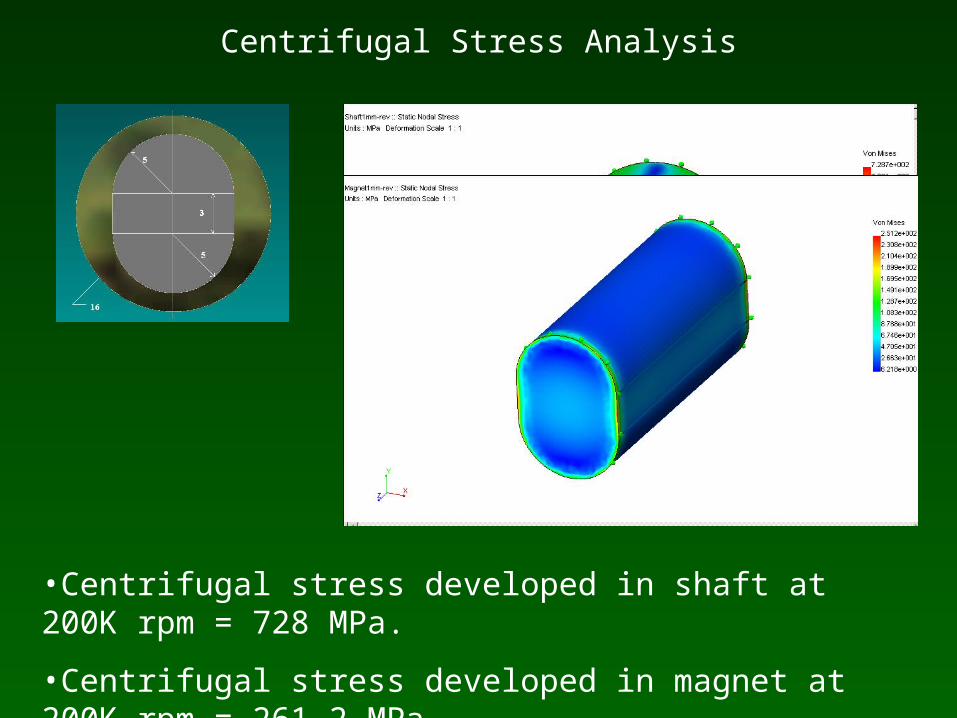
Centrifugal Stress Analysis
•Centrifugal stress developed in shaft at 200K rpm = 728 MPa.
•Centrifugal stress developed in magnet at 200K rpm = 261.2 MPa
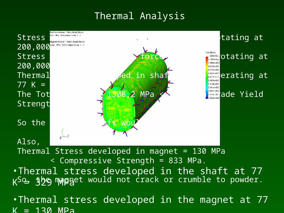
Thermal Analysis
•Thermal stress developed in the shaft at 77 K = 329 MPa
•Thermal stress developed in the magnet at 77 K = 130 MPa
Stress due to centrifugal force in shaft rotating at 200,000 rpm = 728 MPaStress due to centrifugal force in magnet rotating at 200,000 rpm = 251.2 MPaThermal stress developed in shaft due to operating at 77 K = 329 MPaThe Total Stress = 1308.2 MPa < Titanium Grade Yield Strength 1420 MPa
So the titanium shaft would not fail.
Also, Thermal Stress developed in magnet = 130 MPa < Compressive Strength = 833 MPa.
So, the magnet would not crack or crumble to powder.
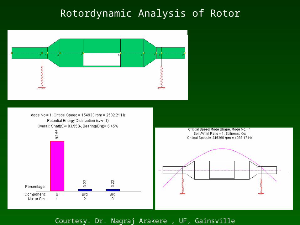
Rotordynamic Analysis of Rotor
Courtesy: Dr. Nagraj Arakere , UF, Gainsville
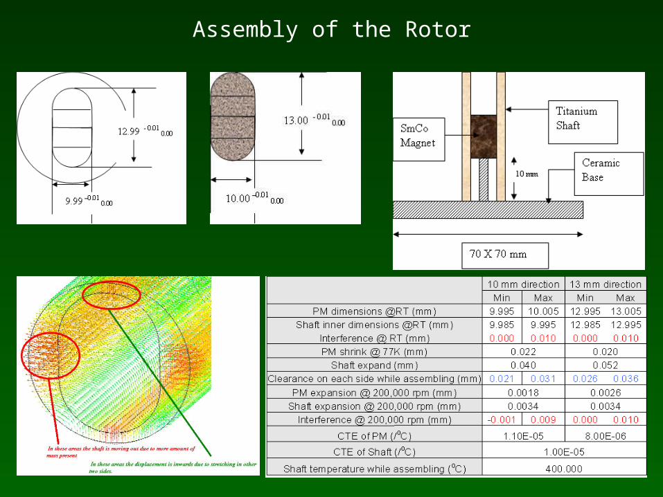
Assembly of the Rotor

Fabrication of PMSM
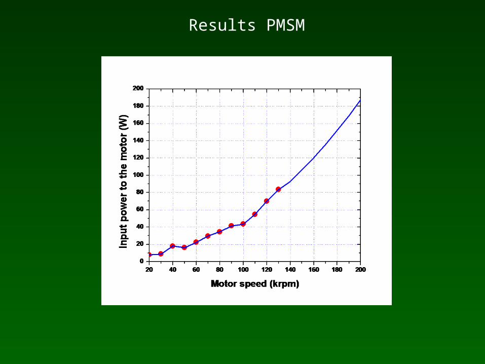
Results PMSM
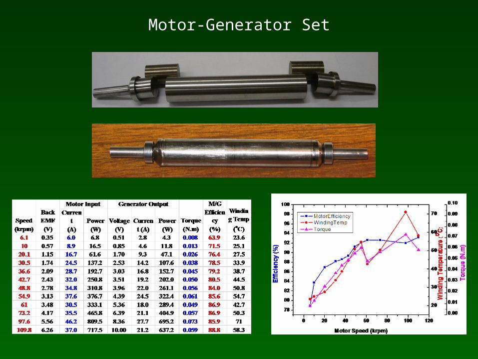
Motor-Generator Set
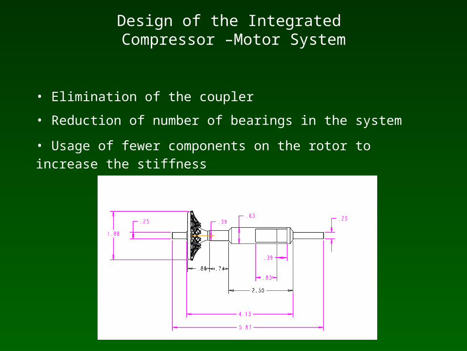
Design of the Integrated Compressor –Motor System
• Elimination of the coupler
• Reduction of number of bearings in the system
• Usage of fewer components on the rotor to increase the stiffness
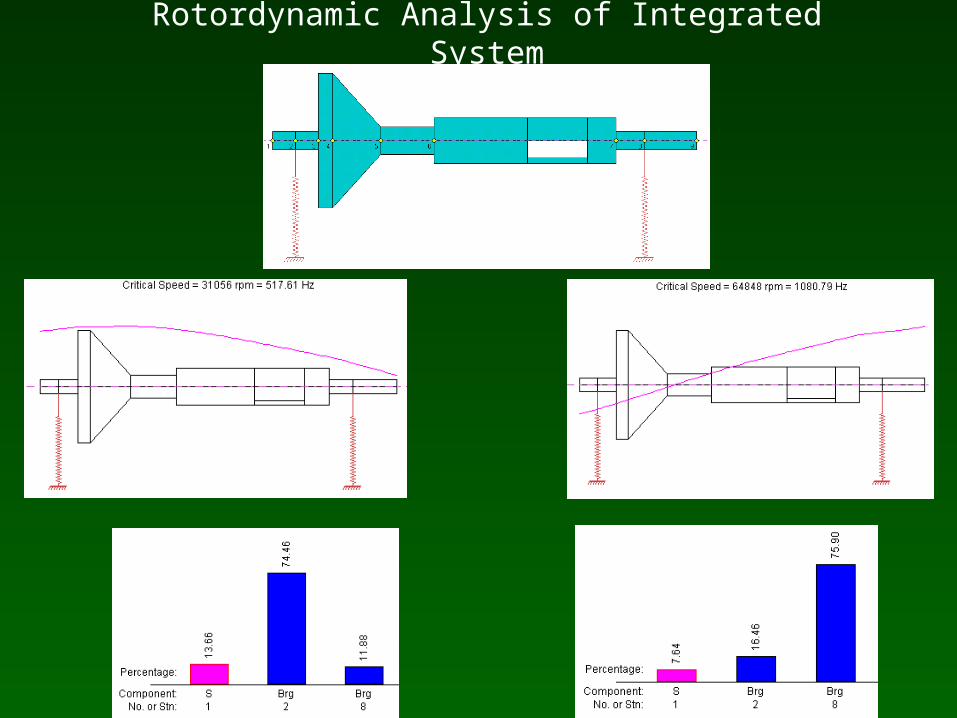
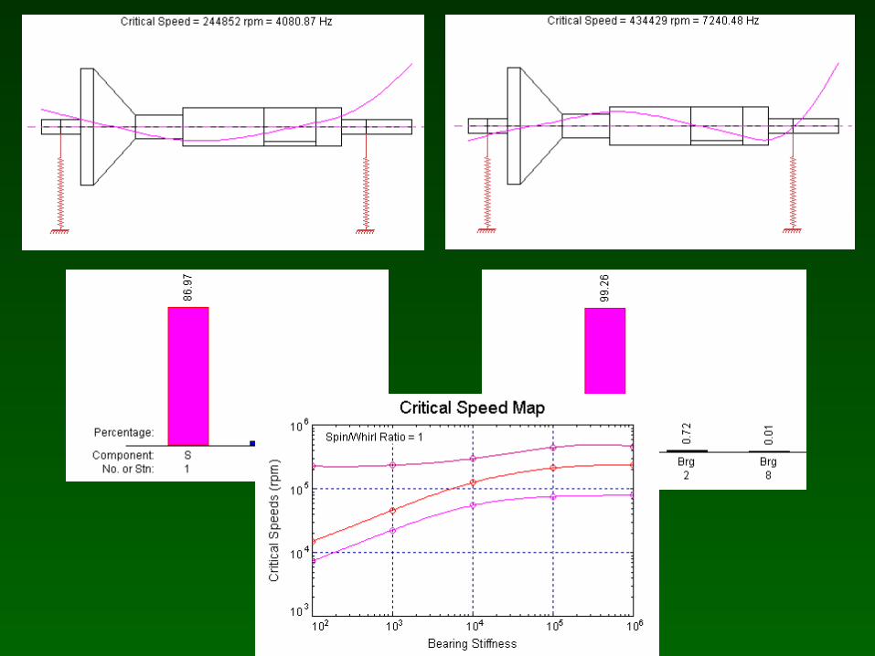
Rotordynamic Analysis of Integrated System

Fabrication of Integrated Rotor

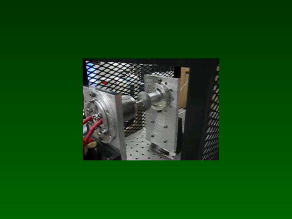
Test Rig Structure
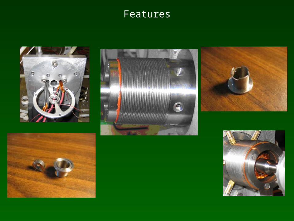
Features

Test Accessories – Electrical
Code ComposerEmulator, DSP and Motor ControllerLow Pass FilterPower Meter
Courtesy: Liping Zheng and Limei Zhou
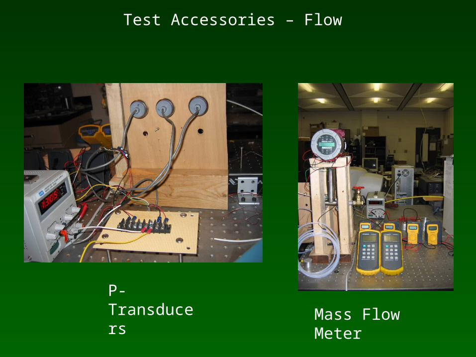
Test Accessories – Flow
P-Transducers
Mass Flow Meter
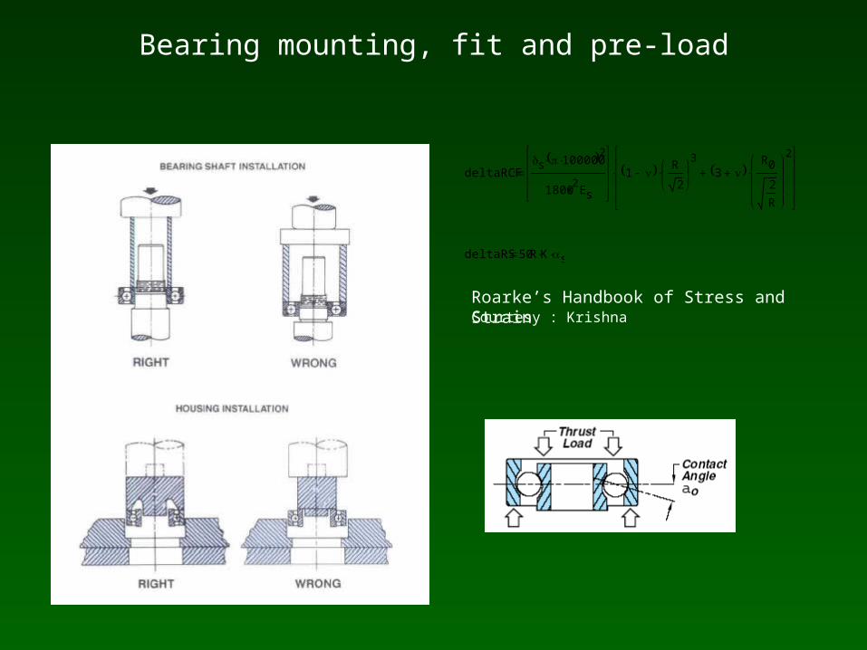
Bearing mounting, fit and pre-load
deltaRCFs 100000 2
1800s2
Es
1 R
2
3
3 R0
2
R
2
deltaRS 50R K s
Roarke’s Handbook of Stress and StrainCourtesy : Krishna
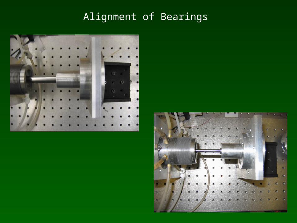
Alignment of Bearings
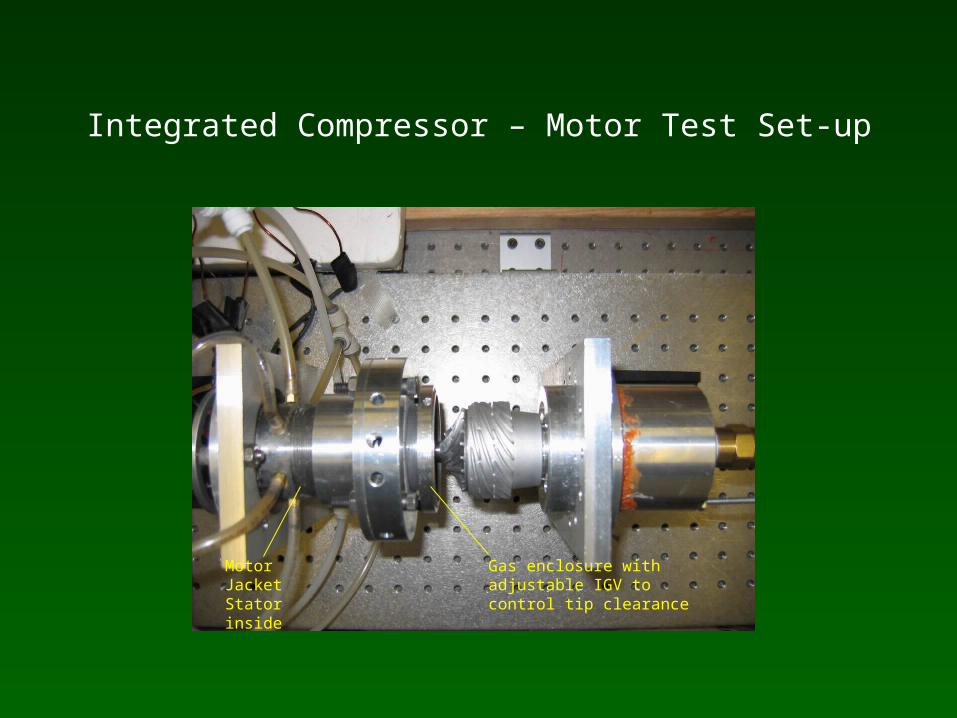
Integrated Compressor – Motor Test Set-up
Motor Jacket Stator inside
Gas enclosure with adjustable IGV to control tip clearance
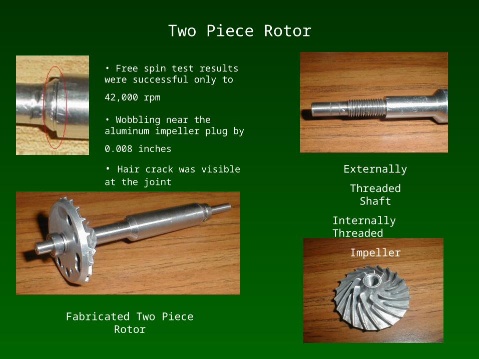
Two Piece Rotor
• Free spin test results were successful
only to 42,000 rpm • Wobbling near the aluminum impeller
plug by 0.008 inches • Hair crack was visible at the joint
Externally
Threaded Shaft
Internally Threaded
Impeller
Fabricated Two Piece Rotor
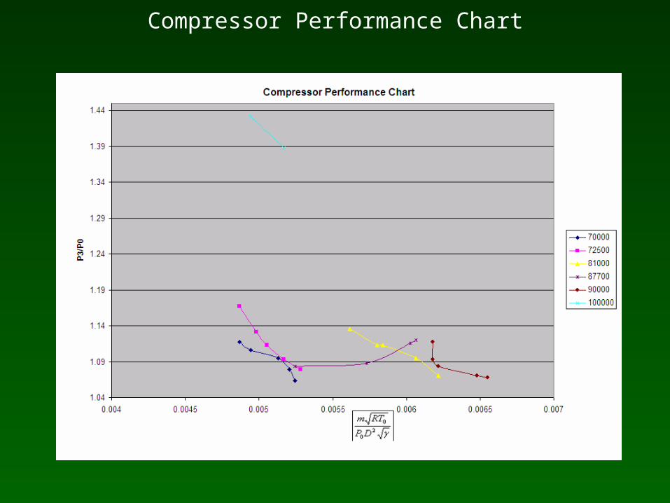
Compressor Performance Chart
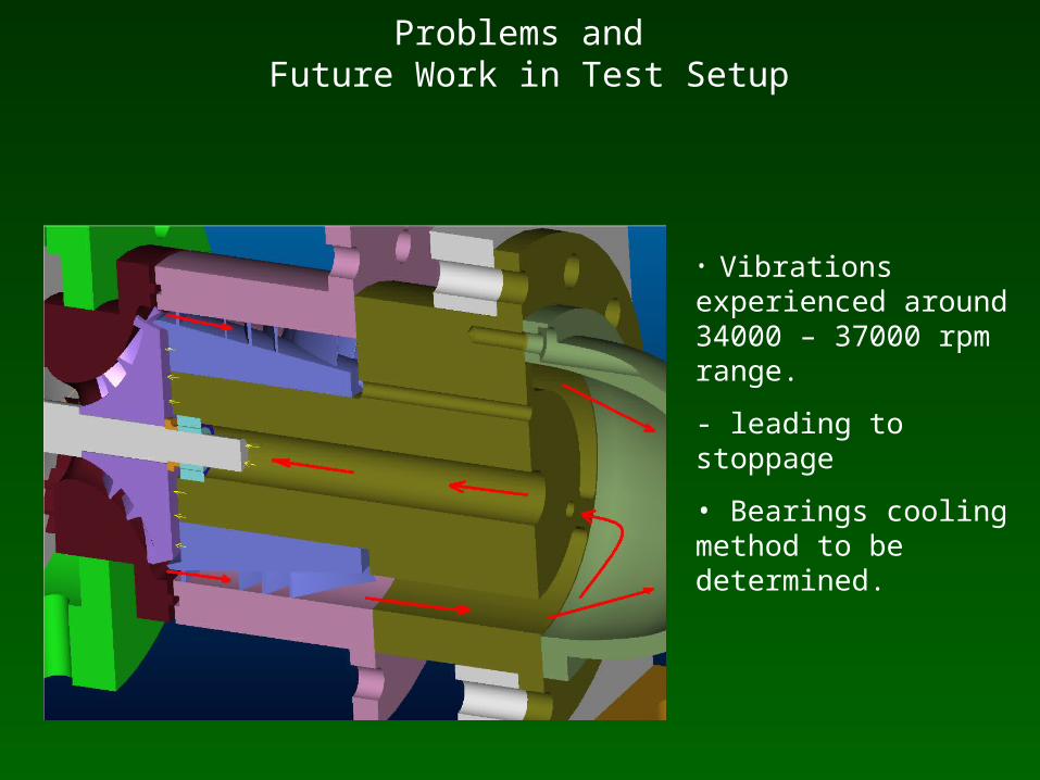
Problems and Future Work in Test Setup
• Vibrations experienced around 34000 – 37000 rpm range.
- leading to stoppage
• Bearings cooling method to be determined.
Conclusion
Initial Compressor-Motor Test Setup developed and tested- Helical Coupler was designed and tested- Alignment method was improved by Reverse Rim Method and Translational
Stages- Components were verified with FARO Arm and re-fabricated
2 KW Permanent Magnet Synchronous Motor designed and tested- Shaft Material Selection, Stress Analysis Performed and Optimized by
Rotordynamic Analysis. Bearing Selection- Fabrication, Assembly Performed and Tested- Motor-Generator set developed to determine motor performance
Integrated Compressor – Motor Structure Designed and Tested
- Versions of Integrated Rotor was designed and tested- Bearing Fit determined, Pre-load structure designed- Innovative procedure for alignment developed- Adjustable IGV developed for control over tip clearance

Thank you