
DESIGN AND OPERATIONS PLAN REPORT - … · Underground piping for digester gas arriving from the...
17
350977 Design and Operations Report 1 Arcadis Canada Inc. (formerly SENES Consultants) DESIGN AND OPERATIONS PLAN REPORT TORONTO HYDRO ENERGY SERVICES INC. ASHBRIDGES BAY BIOGAS COGENERATION PLANT Toronto Hydro Energy Services Inc. (TH Energy) is planning to construct and operate a Biogas Cogeneration Plant located at 7 Leslie Street, Toronto, Ontario (the Site), which is adjacent to the Ashbridges Bay Treatment Plant (ABTP). The Biogas Cogeneration Plant (Cogeneration Plant) is subject to the requirements of the new Green Energy Act and Renewable Energy Approvals (REA) process (O.Reg. 359/09). TH Energy has entered into a long term “Agreement to Lease” with the City of Toronto for the site location, which is currently used as a works yard. Part of the property located at 7 Leslie Street will be used to build the Cogeneration Plant, while the remainder of the land will continue to be used as a works yard by the City of Toronto. This Design and Operations Report is organized into the following sections: 1. Project Description 2. Site Plan 3. Facility Design and Operations Plan 4. Environmental Effects Monitoring Plan 5. Communications and Emergency Response Plan 1. Project Description The proposed TH Energy Cogeneration Plant is classified under O.Reg. 359/09 as a Biogas Facility, and will utilize biogas produced in existing digesters at the ABTP to generate electricity and thermal energy in the form of hot water TH Energy is considering two (2) different configurations for the site: the Cogeneration Plant will generate either 9.912 MW of electricity from seven (7) reciprocating engine generators, rated at 1.416 MW each, or 9.845 MW of electricity from five (5) reciprocating engine generators, rated at 1.969 MW each, under the next phase of the Independent Electricity System Operator (IESO) Process and Systems Upgrade Initiative (PSUI) as part of the SaveOnEnergy program. Electrical connection is through the ABTP electrical distribution system, therefore, the electricity produced by the Facility will be consumed by the ABTP. Process inputs to the Cogeneration Plant include biogas and process water from ABTP; outputs include hot water to ABTP, electricity to ABTP via a step-up transformer, engine generator exhaust (typical combustion emissions consisting primarily of carbon dioxide, carbon monoxide, nitrogen oxides, suspended particulate and sulphur oxides), relatively small quantities of sewage material removed from the biogas stream (to be potentially flared), typical coolants and lubricants consumed during engine generator operations and various packaging materials.
Transcript of DESIGN AND OPERATIONS PLAN REPORT - … · Underground piping for digester gas arriving from the...

350977 Design and Operations Report 1 Arcadis Canada Inc. (formerly SENES Consultants)
DESIGN AND OPERATIONS PLAN REPORT TORONTO HYDRO ENERGY SERVICES INC.
ASHBRIDGES BAY BIOGAS COGENERATION PLANT Toronto Hydro Energy Services Inc. (TH Energy) is planning to construct and operate a Biogas Cogeneration Plant located at 7 Leslie Street, Toronto, Ontario (the Site), which is adjacent to the Ashbridges Bay Treatment Plant (ABTP). The Biogas Cogeneration Plant (Cogeneration Plant) is subject to the requirements of the new Green Energy Act and Renewable Energy Approvals (REA) process (O.Reg. 359/09). TH Energy has entered into a long term “Agreement to Lease” with the City of Toronto for the site location, which is currently used as a works yard. Part of the property located at 7 Leslie Street will be used to build the Cogeneration Plant, while the remainder of the land will continue to be used as a works yard by the City of Toronto. This Design and Operations Report is organized into the following sections:
1. Project Description 2. Site Plan 3. Facility Design and Operations Plan 4. Environmental Effects Monitoring Plan 5. Communications and Emergency Response Plan
1. Project Description
The proposed TH Energy Cogeneration Plant is classified under O.Reg. 359/09 as a Biogas Facility, and will utilize biogas produced in existing digesters at the ABTP to generate electricity and thermal energy in the form of hot water TH Energy is considering two (2) different configurations for the site: the Cogeneration Plant will generate either 9.912 MW of electricity from seven (7) reciprocating engine generators, rated at 1.416 MW each, or 9.845 MW of electricity from five (5) reciprocating engine generators, rated at 1.969 MW each, under the next phase of the Independent Electricity System Operator (IESO) Process and Systems Upgrade Initiative (PSUI) as part of the SaveOnEnergy program. Electrical connection is through the ABTP electrical distribution system, therefore, the electricity produced by the Facility will be consumed by the ABTP. Process inputs to the Cogeneration Plant include biogas and process water from ABTP; outputs include hot water to ABTP, electricity to ABTP via a step-up transformer, engine generator exhaust (typical combustion emissions consisting primarily of carbon dioxide, carbon monoxide, nitrogen oxides, suspended particulate and sulphur oxides), relatively small quantities of sewage material removed from the biogas stream (to be potentially flared), typical coolants and lubricants consumed during engine generator operations and various packaging materials.

350977 Design and Operations Report 2 Arcadis Canada Inc. (formerly SENES Consultants)
2. Site Plan
The area surrounding the proposed Cogeneration Plant is mainly industrial land use, with some nearby recreation areas (i.e., public parks, boat club). The nearest residential receptors are north of Lakeshore Boulevard East, approximately 800 m north of the Site. Figure 1 depicts the site location and vicinity.
FIGURE 1 SITE LOCATION
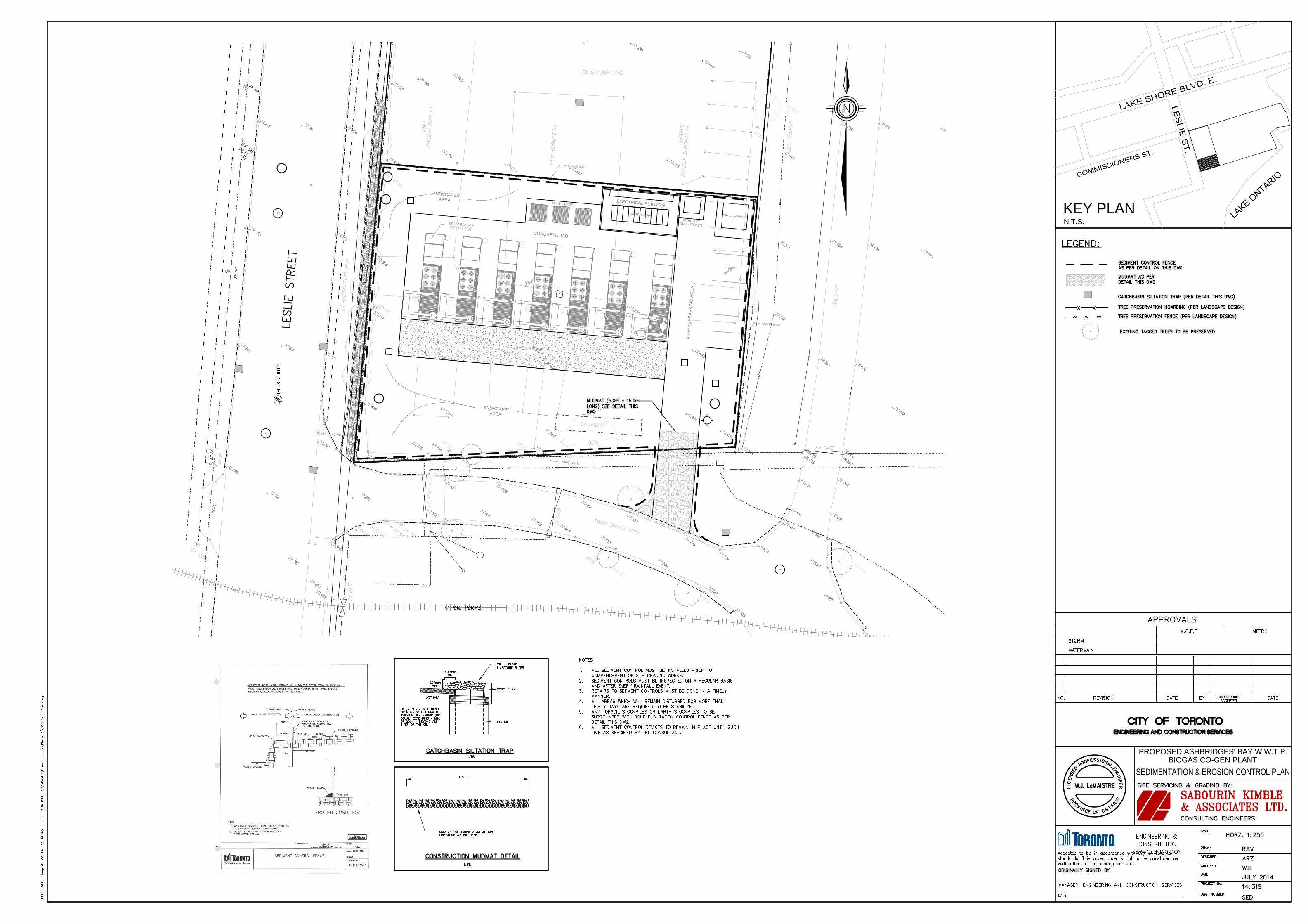
Site plan drawings depicting the site layout and building plans are attached. The ‘Site Servicing Plan’ drawing outlines the proposed enclosure locations, one (1) for each engine generator and another for electrical switch gear. The Site will be surrounded by fencing with a gated entrance road off the existing South Road, which provides access to the ABTP site. Other utility connections outlined in the Site Plans are as follows:
A transformer pad will be located at the northeast corner of the Site, which will connect electricity generated at the Cogeneration Plant to the main ABTP electrical distribution system via underground duct bank.
Underground piping for digester gas arriving from the ABTP connects to each individual engine generator enclosure.
Hot water piping for ABTP processes and cold water return will be located in the same trench as digester gas piping. The existing approved ABTP process water treatment
Ashbridges Bay
Treatment Plant
Proposed Location of
ABTP Biogas
Cogeneration Plant

350977 Design and Operations Report 3 Arcadis Canada Inc. (formerly SENES Consultants)
process will continue to operate. There will be no treatment or disposal of process water at the Cogeneration Plant site; any required disposal of process wastes will be off site.
Water supply for the Cogeneration Plant will be for an outdoor tap and emergency eye wash station, and is provided via galvanized piping from the water main located on Leslie Street.
Small amounts of condensate removed from digester gas will be discharged back to the sewer system via sanitary discharge.
All drawings provided outline the location for the engine generator set enclosures and exhaust stacks. Digester gas arriving at the site will pass through a treatment system, which may require periodic flaring, depending on the final equipment design. If required, a 5 m or 6 m tall flare would be located on the eastern property line at a location to be determined.
The Cogeneration Plant building will include a separate enclosure for electrical switch gear equipment. The enclosure elevations are depicted in Figure 2.
As outlined in the Odour Report prepared under the REA process, biogas will be contained within welded piping prior to combustion within the engine generators. Therefore, there are no odour emissions anticipated from the proposed Cogeneration Plant.
As outlined in the Acoustic Assessment Report prepared under the REA process, the nearest sensitive noise receptor is located approximately 800 m north of the site. Therefore, there are no noise receptors that will be negatively affected by the operation of the Cogeneration Plant.
FIGURE 2 ENCLOSURE ELEVATIONS

350977 Design and Operations Report 4 Arcadis Canada Inc. (formerly SENES Consultants)
3. Facility Design and Operations Plan
The proposed TH Energy Cogeneration Plant will utilize biogas produced in existing digesters at the ABTP to generate electricity and thermal energy in the form of hot water. The biogas is produced by anaerobic digestion of the biodegradable material in municipal sewage waste at the ABTP facility, and is comprised primarily of methane and carbon dioxide. Currently, the biogas is used as fuel to heat water in existing boilers at the ABTP. TH Energy is considering two (2) different configurations for the site: the Cogeneration Plant will generate either 9.912 MW or 9.845 MW of electricity under the next phase of the Independent Electricity System Operator (IESO) Process and Systems Upgrade Initiative (PSUI) as part of the SaveOnEnergy program. Electrical connection is through the ABTP electrical distribution system, therefore, the electricity produced by the Facility will be consumed by the ABTP. Heat resulting from the biogas combustion process in the engine generator sets is recovered from engine cooling, lube oil cooling and from the exhaust flue gases by heat exchangers, which produce the hot water for use at the ABTP. Biogas pipes leading to and hot water pipes leading from the TH Energy Facility will be installed across a shared property line. Maintenance of equipment will occur on regular intervals. General maintenance such as lube oil replacement on the gas fuelled engine generators will take place every 2,000 hours, while a major overhaul of the reciprocating engines will take place every 60,000 hours. Other routine inspections will also be performed on a regular basis.
FIGURE 2 PROCESS FLOW DIAGRAM
POWER TO ABTP
THERMAL ENERGY (HOT WATER) TO
ASHBRIDGES BAY TREATMENT PLANT
LEGEND:
BIOGAS
POWER
EXHAUST GASES
HOT WATER
BIOGAS‐FIRED GENERATOR
BIOGAS SUPPLY
FROM ABTP
BIOGAS TREATMENT
HEAT RECOVERY UNIT
DISCHARGE TO
ATMOSPHERE FLARED TO
ATMOSPHERE

350977 Design and Operations Report 5 Arcadis Canada Inc. (formerly SENES Consultants)
The proposed TH Energy Cogeneration Plant is designed to minimize impacts on the environment. The Site is located near to the Tommy Thompson Park, which is a significant bird nesting area, migration and stop-over and reserve. The enclosures are not reflective, therefore, bird impacts are not expected. Any sewage (less than ½ m3/week of sewage material may be removed from the biogas stream) or waste materials generated during operations (typical coolants and lubricants consumed during engine generator operations) will be stored in site enclosures, and will be disposed of through licensed haulers. The Site will be registered as a hazardous waste generator with reporting completed through the Ministry of Environment Hazardous Waste Information Network (HWIN). Any non-hazardous waste generated at the Site (various packaging materials and office type waste) will be collected in garbage bins located inside enclosures and disposed of by a contracted company. Storm water runoff at the Site currently collects in a storm water sewer located on Leslie St. at the southwest corner of the Site. Four new storm sewers will be installed at the Site as outlined on the Storm Drainage Plan drawing. 4. Environmental Effects Monitoring Plan
Environmental effects from the operation of the proposed Cogeneration Plant have been mitigated to ensure minimal impacts on the surrounding environment. Air and noise emissions will comply with applicable environmental regulations and site specific testing of equipment will be completed. Source testing of engine generator set exhaust emissions will be completed to ensure compliance with O.Reg. 419/05 requirements. An acoustic audit will be completed to ensure any noise emissions from site building entry and exit points are mitigated with sound attenuation equipment as required to meet NPC 205, 232 and 233 documents under Section 9 of the EPA. All applicable environmental regulations will be followed in the disposal of any wastes generated at the site. Regular meetings will be conducted with the existing Neighbourhood Liaison Committee (NLC) developed to facilitate communication regarding operations at the adjacent ABTP.

350977 Design and Operations Report 6 Arcadis Canada Inc. (formerly SENES Consultants)
5. Communications and Emergency Response Plan
A plaque describing the Cogeneration Plant will be placed on the outside front lawn area of the Site. Regular local community meetings with the existing Neighbourhood Liaison Committee (NLC) are currently (and will continue to be) held. These meetings include a discussion of operations at the adjacent ABTP and future operations of the proposed Cogeneration Plant. The Cogeneration Plant site will not be occupied. Emergency contact information will be located at the ABTP Guard House location immediately adjacent to the Site. During a biogas outage (i.e., under emergency conditions only) the engine generator sets will operate using natural gas only, and deliver power to ABTP to allow the plant to continue to operate as required. A project file will be kept at Toronto Hydro offices. Once the facility is operational, a log book including equipment operating conditions will be kept at the Cogeneration Plant. Emergencies will be communicated through public media as required.

ATTACHMENTS
SITE PLAN DRAWINGS
Drawing – A0.2 Site Plan Drawing – L101 Layout Plan Drawing – L102 Planting Plan Drawing – Storm Drainage Plan Drawing – Sedimentation and Erosion Control Plan Drawing – Site Grading Plan Drawing – Site Servicing Plan

4.00 3.00
13.84 0.16
6.00
5.6
1
6.8
1
0.79
0.79
0.90
1.40
3.69
1.40
3.90 2.60
5.6
0
12
.3
5
6.94
12
.0
0
16.36 6.00
43
.0
0
6.0017.00
2.60
2.60
4.00
4.0
0
6.71
12.5
0
2.71 4.00
2.6
0
2.70
2.9
9
11.35
1.4
0
6.2
5
3.50
17
.2
6
5.6
00
.5
0
16.93
CR
US
HE
D S
TO
NE
CONCRETE PAD
ELE
CT
RIC
AL B
UILD
IN
G
PROPOSED HARD SURFACE
(ECO-RASTER MATERIAL - SEE
LANDSCAPE DETAILS)
AU
XIL
IA
RY
TR
AN
SF
OR
ME
R
TRANSFORMER
LA
ND
SC
AP
ED
AR
EA
OIL
S
TO
RA
GE
SW
IT
CH
G
EA
R
BIOGEN STRUCTURE
(TYPICAL)
LIVING WALL
(SEE LAN. DWG.)
OMEGA FENCING
LA
ND
SC
AP
ED
A
RE
A
(S
EE
LA
ND
SC
AP
E P
LA
N
FO
R D
ET
AILS
)
LIVING WALL
(SEE LAN. DWG.)
PROPOSED GATE
CHAINLINK
FENCING
PROPOSED GATE
W/ ELECTRIC LOCK
MARTIN GOODMAN TRAIL
EX. BIKE PATH
EX. LANDSCAPING
(SEE LESLIE STREET GREENING
PHASE 2 DRAWINGS FOR DETAILS)
LESLIE STREET
6.0
0
LIVING WALL
(SEE LAN. DWG.)
10.35
15.85
R
4
.
5
0
R
4
.
5
0
SO
UT
H S
ER
VIC
E R
OA
D
ASPHALT SURFACE
COMPACTED
GRANULAR FILL
PARTING STRIP
COMPACTED
GRANULAR FILL
NEW SIDEWALK
- POURED CONCRETE
OR BRICK PAVERS
(SEE SITE PLAN)
13mm Ø DOWELS
450mm LONG ACROSS
13mm EXPANSION JOINTS
@ 5485mm O.C.
ONE END OF DOWEL
SHALL BE LUBRICATED
WITH A RELEASING AGENT.
NEW POURED
CONC. CURB
(SEE SITE PLAN
FOR EXTENT)
300
100 100
50
15050
150
50
450
ASPHALT SURFACE
25
M
AX
.
GRANULAR FILL
COMPACTED
S
L
O
P
E
U
P
VARIES
PARTING STRIP
NEW POURED
CONCRETE CURB
(SEE SITE PLAN
FOR EXTENT)
13mm Ø DOWELS
450mm LONG ACROSS
13mm EXPANSION JOINTS
@ 5485mm O.C.
ONE END OF DOWEL
SHALL BE LUBRICATED
WITH A RELEASING AGENT.
POURED PATTERNED
CONCRETE ON
50 RIGID INSULATION
(TYP THROUGHOUT)
(SEE SITE PLAN)
100 100
300
50
15050
150
450
50
DRAWING No.:
A0.2SCALE: 1 : 200
7
6
5
4
3
2
1
PROJECT NUMBER: 27143
DATE: SEPT. 5, 2014
Revision DescriptionNo Date Int.
SITE PLAN
TORONTO HYDROENERGY SERVICES
DRAWN BY CHECKED BY
KEY PLAN
M.P. A.B.
GENERAL NOTES1. The contractor shall rectify all disturbed areas to
original condition.
2. Standard drawings of the City of Toronto constitute
part of the plans of the contract.
3. Pavement Grades: Min. 0.5%, Max. 5.0%.
4. Max. slope of landscaped areas to be 1:3.
5. Drainage swales with grades (min. 2%, max. 5%).
6. All conc. curbs shall be 150mm above finished
asphalt unless otherwise noted.
7. All sidewalk finishes to be bordered with conc.
curbs unless otherwise noted.
8. Depress concrete curbs at sidewalks to meet City's
standards for Right-of-way.
9. Provide 1070mm high guardrail where grade
difference exceeds 0.6m. As per OPSD 915.01.
10. Provide toe wall where grade difference exceeds
0.6m.
11. Frost collars are to be provided on curb stops and
valveboxes when located within the limits of the
driveway.
12. All existing roadways are to be maintained during
construction and restored to existing condition or
better post construction.
1. Information shown hereon and site servicing
drawing regarding the size and location of existing
services and/or utilities is furnished as the best
available information and shall be interpreted as
the contractor sees fit with the understanding that
the Owner disclaims all responsibility for its
sufficient and/or accuracy. Contractor to verify all
conditions, before proceeding with any work.
2. All dimensions shall be checked and verified in the
field prior to construction by the contractor and he
shall report any discrepancies immediately to the
Architect.
3. See grading and servicing drawings for sanitary
sewers.
4. See grading and servicing dwgs for storm sewers
and connections.
5. Minimum bedding requirements for storm and
sanitary sewers class 'B' per City standard.
6. Manholes for sanitary and storm sewers to be
precast concrete per City standard.
7. All catchbasins shall be installed in accordance
with City standard.
8. Watermains and water services less than or equal
to 50mm I.D. shall be type "K" copper c/w
compression style joints. Water service
connections shall be installed per City standard.
9. All watermain pipes greater or equal to 100mm I.D.
shall be P.V.C. pipe class 150 and satisfy
A.W.W.A. C900-75 specifications. All fittings shall
be mechanical joint, cement lined cast iron pipe
watermain. Depth of cover shall be 2.10m. Bedding
shall be per City standard.
10. Benching of sanitary/storm service M.H. by builder
to the satisfaction of the Director of Engineering.
11. Minimum clearance of 1.2m from all other services
must be maintained.
12. See grading and servicing dwgs for roof drainage.
13. Watermain to be installed with a minimum 1.7m
cover on property.
SITE SERVICING NOTES
CONCRETE CURB
DEPRESSED CONCRETE CURB
N.T.S.
N.T.S.
DETAIL 'B'
DETAIL 'A'
3rd Submission Drawing 09/03/10
4th Submission 09/05/14 M.P.
LA
KE
S
HO
RE
B
LV
D E
LESLIE ST
NO
RT
H S
ER
VIC
E R
D
SO
UT
H S
ER
VIC
E R
D
SCALE : N.T.S.
LOT AREA 2,701 sq.m
LOT COVERAGE
ELECTRICAL BUILDING 3.1% (83.9 sq.m)
PARKING
6 spaces
(includes 1 accessible parking space)
LANDSCAPED AREA
1174.5 sq.m (43.5%)
HARDSCAPE AREA
CONCRETE 1,108.7 sq.m (41.0%)
ECO-RASTER MATERIAL 336.2 sq.m (12.4%)
SITE STATISTICS
North York, Ontario
M3H 2Z1
Unit 102
LANDSCAPE ARCHITECT: CIVIL ENGINEER:
PLANNER:


CR
US
HE
D S
TO
NE
CO
NC
RE
TE
PA
D
ELE
CT
RIC
AL B
UIL
DIN
G
AS
PH
ALT
P
AR
KIN
G A
RE
A
AU
XIL
LA
RY
TR
AN
SF
OR
ME
R
TR
AN
SF
OR
ME
R
LA
ND
SC
AP
ED
AR
EA
LA
ND
SC
AP
ED
AR
EA
OIL
ST
OR
AG
E
SW
ITC
H G
EA
R
CO
GE
NE
RA
TIO
N
UN
IT (T
YP
ICA
L)
LIV
ING
WA
LL
LIV
ING
W
ALL
OM
EG
A F
EN
CIN
G
LIV
ING
WA
LL
PROPOSED ASHBRIDGES' BAY W.W.T.P.
BIOGAS CO-GEN PLANT
KEY PLAN
N.T.S.
STORM DRAINAGE PLAN
CR
US
HE
D S
TO
NE
CO
NC
RE
TE
PA
D
ELE
CT
RIC
AL B
UIL
DIN
G
AS
PH
ALT
P
AR
KIN
G A
RE
A
AU
XIL
LA
RY
TR
AN
SF
OR
ME
R
TR
AN
SF
OR
ME
R
LA
ND
SC
AP
ED
AR
EA
LA
ND
SC
AP
ED
AR
EA
OIL
ST
OR
AG
E
SW
ITC
H G
EA
R
CO
GE
NE
RA
TIO
N
UN
IT (T
YP
ICA
L)
LIV
ING
WA
LL
LIV
ING
W
ALL
OM
EG
A F
EN
CIN
G
LIV
ING
WA
LL
PROPOSED ASHBRIDGES' BAY W.W.T.P.
BIOGAS CO-GEN PLANT
KEY PLAN
N.T.S.


CR
US
HE
D S
TO
NE
CO
NC
RE
TE
PA
D
ELE
CT
RIC
AL B
UIL
DIN
G
AS
PH
ALT
P
AR
KIN
G A
RE
A
AU
XIL
LA
RY
TR
AN
SF
OR
ME
R
TR
AN
SF
OR
ME
R
LA
ND
SC
AP
ED
AR
EA
LA
ND
SC
AP
ED
AR
EA
OIL
ST
OR
AG
E
SW
ITC
H G
EA
R
CO
GE
NE
RA
TIO
N
UN
IT (T
YP
ICA
L)
LIV
ING
WA
LL
LIV
ING
W
ALL
OM
EG
A F
EN
CIN
G
LIV
ING
WA
LL
79
78
77
76
79
78
77
76
75 75
0510 5 10
7474
79
78
77
76
79
78
77
76
75 75
0510 5 10
7474
PROPOSED ASHBRIDGES' BAY W.W.T.P.
BIOGAS CO-GEN PLANT
KEY PLAN
N.T.S.
SITE SERVICING PLAN