
DESIGN AND MANUFACTURE OF WIND TURBINE BLADES · DNV-OS-J102, Design and Manufacture of wind...
60
DET NORSKE VERITAS STANDARD DNV-OS-J102 DESIGN AND MANUFACTURE OF WIND TURBINE BLADES WORKING DRAFT - 3 OCTOBER 2005
Transcript of DESIGN AND MANUFACTURE OF WIND TURBINE BLADES · DNV-OS-J102, Design and Manufacture of wind...
DET NORSKE VERITAS
STANDARD DNV-OS-J102
DESIGN AND MANUFACTURE OF WIND TURBINE BLADES
WORKING DRAFT - 3 OCTOBER 2005
DNV-OS-J102, Design and Manufacture of wind turbine blades, Working Draft - 3 October 2005 Page 2 of 60
D N V
FOREWORD DET NORSKE VERITAS (DNV) is an autonomous and independent foundation with the objectives of safeguarding life, property and the environment, at sea and onshore. DNV undertakes classification, certification, and other verification and consultancy services relating to quality of ships, offshore units and installations, and onshore industries worldwide, and carries out research in relation to these functions. DNV Offshore Codes consist of a three level hierarchy of documents: — Offshore Service Specifications. Provide principles and procedures of DNV classification, certification, verification and consultancy services. — Offshore Standards. Provide technical provisions and acceptance criteria for general use by the offshore industry as well as the technical basis for DNV offshore services. — Recommended Practices. Provide proven technology and sound engineering practice as well as guidance for the higher level Offshore Service Specifications and Offshore Standards. DNV Offshore Codes are offered within the following areas: A) Qualification, Quality and Safety Methodology B) Materials Technology C) Structures D) Systems E) Special Facilities F) Pipelines and Risers G) Asset Operation H) Marine Operations J) Wind Turbines Amendments and Corrections This document is valid until superseded by a new revision. Minor amendments and corrections will be published in a separate document on the DNV web-site; normally updated twice per year (April and October). To access the web-site, select short-cut options "Technology Services" and "Offshore Rules and Standards" at http://www.dnv.com/ The electronic web-versions of the DNV Offshore Codes will be regularly updated to include these amendments and corrections.
ET ORSKE ERITAS
DNV-OS-J102, Design and Manufacture of wind turbine blades, Working Draft - 3 October 2005 Page 3 of 60
D N V
TABLE OF CONTENTS
TABLE OF CONTENTS ................................................3
LIST OF FIGURES.........................................................4
LIST OF TABLES...........................................................4
SECTION 1 INTRODUCTION...............................5 A. Objectives............................................................5
A 100 Objectives .............................................5 B. Application..........................................................5
B 100 Application............................................5 C. Normative references ..........................................7
C 100 DNV Standards .....................................7 C 200 IEC Type certification standards...........7
D. Informative references.........................................7 D 100 General..................................................7
E. Definitions...........................................................8 E 100 Verbal forms ..............................................8 E 200 Terms.........................................................8
F. Abbreviations and Symbols ..............................12 F 100 Abbreviations...........................................12 F 200 Symbols ...................................................12 F 300 Composite coordinate system ..................13
SECTION 2 MATERIAL QUALIFICATION.....14 A. General ..............................................................14
A 100 General................................................14 A 200 Characteristic Material Properties.......14 A 300 Quality system requirements...............15
B. FRP materials ....................................................15 B 100 General................................................15 B 200 Coupon level ultimate strength qualification ...........................................................16 B 300 Coupon level S-N curve development 17 B 400 Element level qualification .................18 B 500 Detail level qualification.....................18 B 600 Full scale test ......................................18 B 700 Qualification of substitute materials ...18
C. Sandwich core materials....................................18 C 100 Sandwich core materials .....................18
D. Adhesives ..........................................................19 D 100 Paste Adhesives ..................................19 D 200 Adhesive durability considerations.....19
E. Laminated wood................................................19 E 100 Laminated Wood .....................................19
F. Surface Finishing ..............................................20 F 100 Fillers.......................................................20 F 200 Paints and Gel coats.................................20 F 300 Paint Application .....................................20
G. Metallic materials..............................................21 G 100 Metallic materials for bushings etc. ....21
SECTION 3 DESIGN ANALYSIS........................22 A. General ..............................................................22
A 100 Objective.............................................22 A 200 Quality system requirements...............22 A 300 Processes.............................................22 A 400 Composite failure modes ....................24
A 500 Design criteria.....................................25 A 600 Partial safety factors for loads (γf) ......25 A 700 Partial safety factors for consequence of failure (γn) 26 A 800 Partial safety factors for materials (γm)26 A 900 Geometrical Parameters ......................27
B. Verification of input for design loads and tower clearance analysis .......................................................28
B 100 General................................................28 C. Tower clearance ................................................28
C 100 General................................................28 D. Additional Failure modes ..................................28
D 100 Erosion................................................28 D 200 Environmental Protection ...................28 D 300 Lightning.............................................29 D 400 Impact damage....................................29 D 500 Creep...................................................29 D 600 Extreme temperatures in the blade......29 D 700 Substantiation of Repair......................29
SECTION 4 BLADE MANUFACTURING PROCEDURES 30
E. General ..............................................................30 E 100 Manufacturing procedure manuals ..........30
SECTION 5 BLADE TESTING............................32 A. General ..............................................................32
A 100 General................................................32 B. Selection of test blade and specification of testing 32
B 100 Selection of test blade .........................32 B 200 Parts of the blade to be tested..............32 B 300 Natural frequencies and damping determination .........................................................32 B 400 Static testing........................................33 B 500 Fatigue testing.....................................34 B 600 Final static testing ...............................36 B 700 Other tests ...........................................36
C. Quality management of testing..........................36 C 100 General................................................36
D. Reporting...........................................................36 D 100 General................................................36
SECTION 6 DOCUMENTATION REQUIREMENTS ........................................................37
A. General ..............................................................37 A 100 General................................................37 A 200 Design Documents ..............................37 A 300 Technical Documents..........................37 A 400 Work Instructions and Drawings ........37 A 500 Test Documents ..................................37 A 600 Installation and Service Documents....38
SECTION 7 BLADE MANUFACTURE ..............39 A. General ..............................................................39
A 100 General................................................39 APPENDIX A – SIMPLIFIED LINEAR ANALYSIS MODELS........................................................................40
A 100 General................................................40 APPENDIX B – FINITE ELEMENT ANALYSIS .....41
ET ORSKE ERITAS

DNV-OS-J102, Design and Manufacture of wind turbine blades, Working Draft - 3 October 2005 Page 4 of 60
D N V
A 100 Modelling of Structures – General......41 LIST OF FIGURES A 200 Software Requirements .......................42 A 300 Execution of Analysis .........................42
Figure 1 - Wind turbine design and development processes...........................................................................................6
A 400 Evaluation of Results ..........................42 A 500 Validation and Verification.................43
Figure 2 - Composite coordinate system .........................13 APPENDIX C – BUCKLING ANALYSIS..................44 Figure 3- The Building Block Approach .........................15
Figure 4 - Typical R-ratios ..............................................18 A 100 Concepts and Definitions....................44 Figure 5- Processes in the analytical verification of wind turbine blade strength ......................................................23 A 200 General................................................44
A 300 Calculation of Buckling Resistance ....44 Figure 6 - Typical stress-strain relation for a laminate containing 0, 45 and 90 layers .........................................47 A 400 Buckling analysis of individual
components ............................................................46 Figure 7- Interlaminar failure modes...............................52 A 500 Buckling analysis of more complex
elements or entire structures ..................................46 Figure 8 - Typical sandwich structure failure modes.......53 Figure 9- Tabular representation of fatigue loads............55
APPENDIX D – FIBRE FAILURE ANALYSIS ........47 Figure 10 - Matrix representation of fatigue loads ..........55 Figure 11 - A typical Constant Amplitude Lifetime diagram............................................................................57 A 100 General................................................47
A 200 Maximum strain criterion ...................47 A 300 Tsai-Hill criterion ...............................47
A 400 Modified Tsai-Wu criterion ................47 LIST OF TABLES A 500 Special considerations for in-plane compressive loads ..................................................48 A 600 Fracture mechanics approach..............48 Table 1 - DNV Offshore Service Specifications, Standards
and Rules ...........................................................................7 APPENDIX E – MATRIX FAILURE ANALYSIS ....49 Table 2 - IEC Type Certification Standards ......................7
Table 3 - DNV Guidelines for wind turbines ....................7 A 100 General................................................49 Table 4 - Other relevant references ...................................7 A 200 Maximum stress criterion ...................49 Table 5 – Determination of km for a 5th percentile lower limit with 95% confidence for a normal population distribution.......................................................................15
A 300 Puck's criterion....................................49 A 400 In-plane shear failure ..........................50 A 500 Von Mises yield criterion....................51
Table 6 - Uncured constituent testing..............................16 APPENDIX F – INTERLAMINAR FAILURE ANALYSIS.....................................................................52
Table 7 - Cured lamina/laminate testing..........................16 Table 8 - lamina/laminate mechanical property testing...17 Table 9 - laminate fatigue strength testing.......................17 A 100 General................................................52 Table 10 - Recommended adhesive strength characterisation tests........................................................19
A 200 Onset of delamination .........................52 A 300 Delamination growth ..........................52
Table 11 – Typical composite failure modes...................24 APPENDIX G – SANDWICH FAILURE ANALYSIS.........................................................................................53
Table 12 - Partial factors for loads (γf) ............................26 Table 13 – Partial factors for consequence of failure (γn)26 Table 14 - Partial safety factors for materials (γm) for FRP, laminated wood, and adhesives .......................................27
A 100 General................................................53 A 200 Typical sandwich failure modes .........53
Table 15 - Critical blade manufacturing processes..........30 A 300 Sandwich core ultimate failure ...........53 Table 16 - Static test assessment criteria .........................34 A 400 Sandwich core yielding.......................54 Table 17 - Fatigue test assessment criteria ......................35 A 500 Sandwich Interface..............................54 Table 18- Typical failure modes of FRP cores ................53 A 600 Sandwich structure buckling...............54
APPENDIX H – FATIGUE LIMIT STATE ANALYSIS.....................................................................55
A 100 General................................................55 A 200 Cyclic Fatigue .....................................55 A 300 Fibre failure in fatigue ........................56 A 400 Change of elastic properties................56 A 500 Initiation of fatigue damage ................56 A 600 Growth of fatigue damage ..................57
APPENDIX I – IMPACT DAMAGE...........................58 A 100 General................................................58 A 200 Detailed Considerations ......................58
ET ORSKE ERITAS
DNV-OS-J102, Design and Manufacture of wind turbine blades, Working Draft - 3 October 2005 Page 5 of 60
D N V
SECTION 1 INTRODUCTION
A. Objectives A 100
ith the present ons.
---e
loads and partial safety factors as specified in IEC 61400-1.
B 100
design, manufacture and test of individual blade types.
e relevant justification for procedures and qualification.
d a specific part concerning blade design and manufacture.
can be
—
The verification is
—
—
the first step are used as u
pro tical for the design will be verified.
Objectives
101 This standard provides principles, technical requirements and guidance for the design and manufacture of wind turbine blades. The objectives of this standard are to provide:
— The design and manufacturing requirements for wind turbine blades subject to DNV certification.
— A guideline for designers, manufacturers, operators, and regulators of wind turbines.
— A technical and contractual reference document between clients, contractors, suppliers, consultants and third parties relating to the design, and manufacture of wind turbine blades.
— Detailed interpretation of IEC WT 01 to aid in the type certification of wind turbine blades.
— Supplementary interpretation of ISO 9000 for certification of quality management systems for the design and manufacturing of wind turbine blades.
— Supplementary standard for Manufacturer Product Quality Assessment (MPQA) services.
— Supplementary interpretation of ISO 17025 for certification of blade test laboratories.
— Detailed standard for third party blade manufacturing inspection.
Guidance note: The type certification of blades according to IEC WT 01 involves design evaluation (verification of material qualification, design calculation and work instructions), manufacturing evaluation (inspection of the manufacturing of one blade) and testing of blades. The IEC WT 01 design evaluation will both cover the generic and specific elements of the design documentation. Verification of the generic elements will only be carried out in details if these elements are critical for the specific design. The IEC WT 01 blade testing evaluation is normally carried out as a review of test report from an accredited laboratory and a report for manufacturing of the test blade. The IEC WT 01 manufacturing evaluation is normally carried out only once. The evaluation is carried out when the manufacturer consider tools (moulds) and quality procedures ready for serial production. Often the quality procedures are in development during the manufacturing of the prototype test blade(s). In such cases the manufacturing evaluation is carried out at a later stage and the documentation for manufacturing of the test blades is reviewed in the light of the final tools. If design, materials or manufacturing procedures are changed necessary elements of design verification, testing and manufacturing evaluation must be repeated before the IEC type certificate can be reissued. DNV may offer additional services to the IEC WT 01 type certification to assist the manufacturer in developing and maintaining the quality system, to enable a faster type approval process for new blade designs and to inspect blade manufacturing as a third party. These services can be arranged as MPQA, ISO 9000 certification, ISO 17025 certification of blade test laboratories
and/or project related blade third party manufacturing inspection. The basis for these additional services is provided wstandard as it is divided in self contained secti
-n-d---o-f---G-u-i-d-a-n-c-e---n-o-t-e---
102 This standard does not cover details for the determination of characteristic loads for wind turbine blades. The intended safety level will be achieved when design loads are calculated on the basis of characteristic
B. Application Application
101 Manufacturing and design of wind turbine blades is normally carried out in both generic and specific levels by the manufacturer. The generic level involves the qualification of design procedures, materials, manufacturing and test methods. The specific level involves
102 The wind turbine blade manufacturer are to establish and control general design procedures, qualification of materials, manufacturing procedures and applicable test procedures through their quality system, i.e. through revision-controlled manuals. These manuals are to be self-contained and preferably provide th
103 This standard is divided into both a generic part concerning documentation of the qualification process, an
104 Type certification of wind turbine blades carried out in three steps as illustrated in Figure 1:
The first step covers verification of the blade manufacturer’s procedural manuals for control of design calculations, materials qualification, manufacturing and blade testing.carried out on a generic level. The second step involves approval of the specific design which is carried out according to the procedure manuals verified in the first step and documented in terms of design drawings, work instructions, design reports and test reports. The third step consists of inspection of manufacturing of individual blades according to the design drawings and work instructions verified in the second step. The procedural manuals verified ing idance for this inspection.
105 Type certification is limited to a specific design, and may not involve the complete verification of material qualification and other generic procedures. Only those elements of the material qualification and generic
cedures deemed cri
ET ORSKE ERITAS

DNV-OS-J102, Design and Manufacture of wind turbine blades, Working Draft - 3 October 2005 Page 6 of 60
DET NORSKE VERITAS
Guidance note: Both the designer and manufacturer must decide on how to communicate the design and manufacturing process to the certifying body. In cases where the design or manufacture is based on prior
certification, the prior-certification sought must be clearly stated and referenced. All generic and specific documentation shall also be
---e-n-d---o-f---G-u-i-d-a-n-c-e---n-o-t-e--- clearly identified.
Figure 1 - Wind turbine design and development processes

DNV-OS-J102, Design and Manufacture of wind turbine blades, Working Draft - 3 October 2005 Page 7 of 60
D N V
C. Normative references C 100 DNV Standards
101 The standards in Table 1 include provisions, which through reference in this text constitute provisions of this standard.
Table 1 - DNV Offshore Service Specifications, Standards and Rules
Reference Title DNV-OS-B101 Metallic materials DNV-OS-C501 Composite Components
DNV-OS-J101 Design of Offshore Wind Turbine Structures
DNV Guidelines for Certification of Wind Turbine Power Plants
C 200 IEC Type certification standards
201 The standards in Table 2 include provisions, which through reference in this text constitute provisions of this standard.
Table 2 - IEC Type Certification Standards
Reference Title IEC WT 01 IEC System for Conformity Testing and
Certification of Wind Turbines, Rules and Procedures
IEC61400-1 Wind Turbines Generator Systems – Part 1: Safety Requirements
IEC61400-23 Full Scale Testing of Wind Turbine Blades
IEC61400-24 Lightning Protection for Wind Turbines
Guidance note: The number of latest edition of DNV documents may be found in the publications list at the DNV website www.dnv.com. The latest edition of DNV-OS-C501 may be read in the viewing area for offshore standards on www.exchange.dnv.com. ---e-n-d---o-f---G-u-i-d-a-n-c-e---n-o-t-e---
D. Informative references D 100 General
101 The documents in Table 3 and Table 4 include acceptable methods for fulfilling the requirements in this standard.
Table 3 - DNV Guidelines for wind turbines
Reference Title DNV/RISØ Guidelines for Design of Wind Turbines
Table 4 - Other relevant references
Reference Title ASTM C297 Determination of the core flat wise tension
strength of sandwich structures. ASTM C613 Standard Test Method for Constituent
Content of Composite Prepreg by Soxhlet Extraction
ASTM D 5379 Standard Test Method for Shear Properties of Composite Materials by the V-Notched Beam Method
ASTM D1002 Standard Test Method for Apparent Shear Strength of Single-Lap-Joint Adhesively Bonded Metal Specimens by Tension Loading (Metal-to-Metal)
ASTM D1781 Standard Test Method for Climbing Drum Peel for Adhesives
ASTM D2344 Standard Test Method for Short-Beam Strength of Polymer Matrix Composite Materials and Their Laminates
ASTM D2584 Standard Test Method for Ignition Loss of Cured Reinforced Resins
ASTM D2734 Standard Test Methods for Void Content of Reinforced Plastics
ASTM D3039 Standard Test Method for Tensile Properties of Polymer Matrix Composite Materials
ASTM D3167 Standard Test Method for Floating Roller Peel Resistance of Adhesives
ASTM D3171 Standard Test Methods for Constituent Content of Composite Materials
ASTM D3410 Standard Test Method for Compressive Properties of Polymer Matrix Composite Materials with Unsupported Gage Section by Shear Loading
ASTM D3479 Standard Test Method for Tension-Tension Fatigue of Polymer Matrix Composite Materials
ASTM D3528 Standard Test Method for Strength Properties of Double Lap Shear Adhesive Joints by Tension Loading
ASTM D3529 Standard Test Method for Matrix Solids Content and Matrix Content of Composite Prepreg
ASTM D3530 Standard Test Method for Volatiles Content of Composite Material Prepreg
ASTM D3531 Standard Test Method for Resin Flow of Carbon Fibre-Epoxy Prepreg
ASTM D3532 Standard Test Method for Gel Time of Carbon Fibre-Epoxy Prepreg
ASTM D3776 Standard Test Methods for Mass Per Unit Area (Weight) of Fabric
ASTM D5528 Standard Test Method for Mode I Interlaminar Fracture Toughness of Unidirectional Fiber-Reinforced Polymer
ET ORSKE ERITAS

DNV-OS-J102, Design and Manufacture of wind turbine blades, Working Draft - 3 October 2005 Page 8 of 60
D N V
Matrix Composites
ASTM D5868 Standard Test Method for Lap Shear Adhesion for Fibre Reinforced Plastic (FRP) Bonding
ASTM D695 Standard Test Method for Compressive Properties of Rigid Plastics
ASTM D792 Standard Test Methods for Density and Specific Gravity (Relative Density) of Plastics by Displacement
ASTM E1252 Standard Practice for General Techniques for Obtaining Infrared Spectra for Qualitative Analysis
ASTM E1356 Standard Test Method for Assignment of the Glass Transition Temperatures by Differential Scanning Calorimetry
ASTM E1545 Standard Test Method for Assignment of the Glass Transition Temperature by Thermo Mechanical Analysis
ASTM E168 Standard Practices for General Techniques of Infrared Quantitative Analysis
Danish Energy Agency
Recommendation for Design, Documentation and Test of Wind Turbine Blades.
ISO 17025 General requirements for the competence of calibration and testing laboratories
ISO 3207 ISO standards handbook – statistical methods
ISO 527 Plastics – Determination of Tensile Properties
ISO 9001:2000 Quality management systems, requirements
MIL-HDBK-17-1F
Volume 1. Polymer Matrix Composites Guidelines for Characterization of Structural Materials
MIL-HDBK-17-3F
Volume 3. Polymer Matrix Composites Materials Usage, Design, And Analysis
Guidance note: The latest edition of the publications issued from Danish Energy Agency can be found at www.dawt.dk---e-n-d---o-f---G-u-i-d-a-n-c-e---n-o-t-e---
E. Definitions E 100
E 200
function for load effect.
distribution function for resistance with 95% confidence.
function for material strength with 95% confidence.
Verbal forms
101 Shall: Indicates a mandatory requirement to be followed for fulfilment or compliance with the present standard. Deviations are not permitted unless formally and rigorously justified, and accepted by all relevant contracting parties.
102 Should: Indicates a recommendation that a certain course of action is preferred or is particularly suitable. Alternative courses of action are allowable under the standard where agreed between contracting parties, but shall be justified and documented.
103 May: Indicates permission, or an option, which is permitted as part of conformance with the standard.
104 Can: Requirements with can are conditional and indicate a possibility to the user of the standard.
105 Agreement, or by agreement: Unless otherwise indicated, agreed in writing between contractor and purchaser.
Terms
201 Abnormal load: Wind load resulting from one of a number of severe fault situations for the wind turbine, which results in activation of system protection functions. Abnormal wind loads are in general less likely to occur than loads from any of the normal wind load cases considered for the ULS.
202 Adhesive: A substance capable of holding two materials together by surface attachment.
203 Aeroelastic: Concerned with the interactions between aerodynamic forces and structural deformation, in both static and dynamic cases.
204 Barcol hardness: A hardness value on a 0 to 100 scale obtained by measuring the resistance to penetration of a sharp steel point under spring loading.
205 Carbon fibres: Fibres made from a precursor by oxidation and carbonisation, and not having a graphitic structure.
206 Characteristic Load: The reference value of a load to be used in the determination of the design load. The characteristic load is normally based upon a defined quantile in the upper tail of the distribution function for load.
207 Characteristic load effect: The reference value of a load effect to be used in the determination of the design load effect. The characteristic load effect is normally based upon a defined quantile in the upper tail of the distribution
208 Characteristic resistance: The reference value of a structural strength to be used in the determination of the design resistance. The characteristic resistance is normally based upon a 5% quantile in the lower tail of the
209 Characteristic material strength: The nominal value of a material strength to be used in the determination of the design strength. The characteristic material strength is normally based upon a 5th percentile in the lower tail of the distribution
ET ORSKE ERITAS

DNV-OS-J102, Design and Manufacture of wind turbine blades, Working Draft - 3 October 2005 Page 9 of 60
D N V
210 Characteristic value: A representative value of a load variable or a resistance variable. For a load variable, it is a high but measurable value with a prescribed probability of not being unfavourably exceeded during some reference period. For a resistance variable it is a low but measurable value with a prescribed probability of being favourably
referring to the variability of a sample data set, and is la
ral member, usually foam or balsa, of dwich con
C):
of the o
d.
xposed to.
222 Fatigue Limit States (FLS): Related to the states of e
224 Fibre Reinforced Plastic (FRP): A generic term for p
225 ous strand of material used aterials due to its high
axial strength and modulus. Also referred to as a filament.
227 Fill: The transverse yarns in a woven fabric running n
l coat: A resin system applied to a mould surface
ible change in an p
(Tg): The x
formance Liquid Chromatography (HPLC): The analysis of resin composition through the
lv
237 Inclusion: A physical discontinuity within a ri
roperties.
c
easuring, examination, testing, gauging one or more characteristics of
exceeded.
211 Coefficient of Variation (COV): A statistical term
calcu ted by dividing the standard deviation by the mean.
212 Core: The centa san struction to which the faces of the sandwich skin are bonded.
213 Creep: The time-dependent part of strain resulting from an applied stress.
214 Cure cycle: The time/temperature/pressure cycle used to cure a thermosetting resin system or prepreg.
215 Cure: To irreversibly change the properties of a thermosetting resin by chemical reaction.
216 Design limits: Maximum or minimum values used in a design.
217 Differential Scanning Calorimetry (DSMeasurement of the energy absorbed (endotherm) or produced (exotherm) as a resin system is cured.
218 Environmental conditions: Characteristicsenvir nment (altitude, temperature, humidity, etc.) which may affect the wind turbine’s behaviour.
219 Expected value: The mean value, e.g. the mean value of a load during a specified time perio
220 Extreme loads: The maximum expected design loads the wind turbine blade is e
221 Fatigue critical: Structure with a predicted fatigue life near the design fatigue life.
fatigu failure due to the cumulative damage effect of cyclic loading.
223 Fatigue: Degradation of the material caused by cyclic loading.
a com osite material consisting of a polymeric matrix, and a reinforcing fibre.
Fibre: A single homogenas a principal constituent in FRP m
226 Filament: See above.
perpe dicular to the warp. Also referred to as a weft.
228 Geto provide an improved surface for the finished FRP material.
229 Gel time: The amount of time taken for a resin to advance to the gelation point.
230 Gelation: The point in a resin’s cure cycle where resin viscosity exceeds a specified value.
231 Glass Transition: The reversamor hous polymer from a hard and relatively brittle condition to a viscous or rubbery one.
232 Glass Transition Temperature appro imate midpoint of the temperature range over which the glass transition takes place in a polymer.
233 Guidance note: Information in the standards in order to increase the understanding of the requirements.
234 Gust: Sudden and brief increase of the wind speed over its mean value.
235 Hand lay up: The process of successive build up of plies in a mould by hand.
236 High Per
disso ing of a resin in solution, and then analysing through selective elution.
mate al, usually consisting of encapsulated solid material, often degrading the structural p
238 Independent third parties: Accredited or nationally approved certification bodies.
239 Infrared Spe troscopy: The qualitative assessment of polymer constituents through infrared analysis.
240 Inspection: Activities such as m
an object or service and comparing the results with specified requirements to determine conformity.
241 Interface: The boundary between individually distinguishable constituents of an FRP material or joint.
242 Interlaminar shear: Shearing force tending to produce a relative displacement between two laminae in a laminate.
ET ORSKE ERITAS

DNV-OS-J102, Design and Manufacture of wind turbine blades, Working Draft - 3 October 2005 Page 10 of 60
D N V
243 Interlaminar: Descriptive term pertaining to an object, event, or potential field referenced as existing between two or more adjacent laminae.
ill be placed on the mould to form the nat
: A state beyond which the structure no r
ation, displacement, motion, etc.
er with d
: Statistical mean over observation period.
conditions, and expressed as a percentage of the mass of the moist
m
255 Mould: The cavity into which the FRP material is
257c
fshore standards are
DNV’s interpretation of
e
rthotropic: Having three mutually perpendicular planes of elastic symmetry.
l ply is
aration.
h molecular weight organic o
ugh u
he resin is partially cured and ie
his behalf, responsible for procuring materials, components er
ated in the DNV offshore standards or other codes and standards cited by DNV.
ed. Redundancy can be achieved for instance by strengthening or introducing
a
mer and their associated hardeners, catalysts, accelerator, etc., which can be
244 Isotropic: Having uniform properties in all directions.
245 Kitting: The process of assembling cut plies in the order in which they wlami e during lay up.
246 Lamina: A single ply or layer in a laminate made up of a series of layers.
247 Laminae: The plural of lamina.
248 Laminate: A product made by the bonding of individual laminae together.
249 Limit Statelonge satisfies the requirements. The following categories of limit states are of relevance for structures: ultimate limit state (ULS), fatigue limit state (FLS), and serviceability limit state (SLS).
250 Load effect: Effect of a single design load or combination of loads on the equipment or system, such as stress, strain, deform
251 Mat: A fibrous material consisting of randomly chopped, short, or swirled fibres loosely held togetha bin er.
252 Matrix: The essentially homogenous constituent of an FRP material that binds and protects the fibres.
253 Mean
254 Moisture content: The amount of moisture in a material determined under specified
speci en.
placed, cured, and takes its final form.
256 Neat resin: Resin to which nothing (additives, reinforcements, and so on) has been added.
Non-destructive testing (NDT): Structural tests and inspe tion of welds by visual inspection, radiographic testing, ultrasonic testing, magnetic particle testing, penetrant testing and other non-destructive methods for revealing defects and irregularities.
258 Offshore Standard: The DNV ofdocuments which presents the principles and technical requirements for design of offshore structures. The standards are offered as
engin ering practice for general use by the offshore industry for achieving safe structures.
259 O
260 Partial safety factor method: Method for design where uncertainties in loads are represented by a load factor and uncertainties in strengths are represented by a material factor.
261 Peel Ply: A layer of open-weave material applied directly to the surface of a prepreg lay up. The peeremoved from the cured laminate immediately before bonding, leaving a clean surface that needs no additional surface prep
262 Ply drop: The transition point in a laminate between different thicknesses, or number of lamina layers.
263 Ply: The layers (lamina) that make up a stack (laminate).
264 Polymer: A higcomp und, whose structure can be represented by a repeated small unit.
265 Pot life: The length of time that a catalysed thermosetting resin system retains a viscosity low enoto be sed in processing.
266 Prepreg: Ready-to-mould material in roving form (cloth, mat, unidirectional fibre, or paper) impregnated with resin and stored for use. Tsuppl d to the manufacturer for finishing and curing.
267 Purchaser: The owner, or another party acting on
or s vices intended for the design, construction or modification of a structure.
268 Quasi-isotropic laminate: A laminate approximating isotropy by orientation of plies in several or more directions.
269 Recommended Practice (RP): The recommended practice publications cover proven technology and solutions which have been found by DNV to represent good practice, and which represent one alternative for satisfying the requirements stipul
270 Redundancy: The ability of a component or system to maintain or restore its function when a failure of a member or connection has occurr
altern tive load paths.
271 Resin system: A poly
ET ORSKE ERITAS

DNV-OS-J102, Design and Manufacture of wind turbine blades, Working Draft - 3 October 2005 Page 11 of 60
D N V
conv ted to a solid by application of energy, normally in the form of elevated temperatu
erre.
, etc., required for the intended processing and final product.
bundle with little or no twist.
ry fashion due to e.g., excessive deformations, ib
spond to tolerance criteria applicable to normal
bstrate: the material to which a paint or adhesive
n untwisted bundle of continuous fibres, commonly referring to the glass and carbon fibres used in
ir
, which forms part of the support structure for a wind turbine. For offshore wind
e
e.
load carrying resistance.
of multiple veneers.
or a service is in accordance with specified requirements.
laminate. Voids are incapable of transferring
r an
293 Wind shear: Variation of wind speed across a plane perpendicular to the wind direction.
294 Woven fabric: A material constructed by interlacing yarns or fibres to form basic fabric patterns.
295 Yarn: An assemblage of twisted fibres to form a continuous length suitable for use in woven fabric.
272 Resin: A mixture of resin and ingredients such as catalyst, initiator, diluents
273 Roving: A number of yarns collected into a parallel
274 S-N diagram: The plot of stress against number of cycles to fatigue failure.
275 Scheduled maintenance: Preventive maintenance carried out in accordance with an established time schedule.
276 Serviceability Limit State (SLS): Concerns those states at which the structure starts to behave in an unsatisfactoor v ration. Implies that deformations in excess of tolerance without exceeding the load-carrying capacity i.e. they correuse.
277 Suis bonded.
278 Tack: Stickiness of an adhesive or FRP prepreg material.
279 Tape: Unidirectional prepreg fabricated in specified widths.
280 Thermoplastic: Capable of being repeatedly softened by an increase in temperature, and capable of being moulded or extruded in this stage.
281 Thermosetting: A plastic that, when cured by application of heat or chemical means, changes into a substantially infusible and insoluble material.
282 Tow: a
uni d ectional composites.
283 Tower: Structural component
turbin structures, this usually extends from somewhere above the still water level to just below the nacelle of the wind turbin
284 Ultimate Limit States (ULS): Concerns those states related to the limit of load-carrying capacity i.e. to maximum
285 Unidirectional laminate: A composite laminate in which substantially all of the fibres are oriented in the same direction.
286 Veneer: A thin sheet of wood sliced or peeled on a veneer machine. Plywood is then comprised
287 Verification: Examination to confirm that an activity, a product
288 Void Content: Volume percentage of voids (usually less than 1%) in a properly cured composite.
289 Voids: Air or gas that has been trapped and cured into a structural stresses.
290 Volatiles: Materials in a resin formulation, such aswate d alcohol, capable of being driven off as vapour at room temperature or during an elevated temperature cure.
291 Warp: The yarn running lengthwise in a woven fabric.
292 Weft: The transverse yarns in a woven fabric running perpendicular to the warp, also referred to as fill.
ET ORSKE ERITAS

DNV-OS-J102, Design and Manufacture of wind turbine blades, Working Draft - 3 October 2005 Page 12 of 60
D N V
F. Abbreviations and Symbols F 100 Abbreviations
101 Abbreviations as used in this standard.
Abbreviation In full ASTM American Society for Testing and Materials CAL Constant Amplitude Loading CFRP Carbon Fibre Reinforced Plastics COV Coefficient Of Variation CPT Cured Ply Thickness DNV Det Norske Veritas DSC Differential Scanning Calorimetry FAW Fibre Areal Weight FE Finite Element FEA Finite Element Analysis FLS Fatigue Limit State FRP Fibre Reinforced Plastics FV Fibre Volume IEC International Electro technical Commission ILSS Inter Laminar Shear Strength IR Infra Red ISO International Standards Organisation MPa Mega Pascal (1 million Pascal) PVC Poly Vinyl Chloride SLS Serviceability Limit State SRF Safety Reserve Factor UD Uni Directional ULS Ultimate Limit State UV Ultra Violet
F 200 Symbols
201 Latin characters
E Young’s modulus
x Sample mean
F Load
fd Design resistance or capacity
fk Characteristic stress Fk Characteristic load G Shear modulus, or strain energy release rate Gcritical Critical strain energy release rate Hn Tsai-Wu interaction parameter P Load Pe Elastic critical load Pf Ultimate failure load R Resistance Rk Characteristic resistance
s Sample standard deviation
Sd Local stress or strain
202 Greek characters
γA Partial analysis factor
γef Partial factor for error in fatigue formulation
γf Partial load factor
γm Partial material resistance factor
γn Partial consequence of failure factor
γsf Partial factor for blade to blade variation α Strain amplitude ε Strain εe Elastic critical strain εn Principal strain µ Population mean ρ Density σ Population standard deviation σe Elastic critical stress σn Principal stress τ Shear stress υ Coefficient of variation
203 Subscripts
A Analysis factor c Compressive strength corr Corrected crit Critical e Elastic critical eff Effective equivalent Equivalent f Fibre or failure k Characteristic lin Linear m Material nn Ply/lamina coordinate system nonlin Non linear t Tensile strength test Test xx Laminate coordinate system
ET ORSKE ERITAS
DNV-OS-J102, Design and Manufacture of wind turbine blades, Working Draft - 3 October 2005 Page 13 of 60
D N V
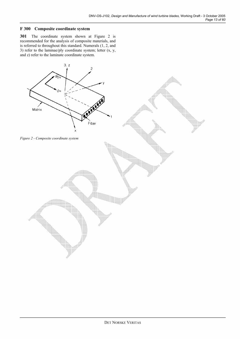
F 300 Composite coordinate system 301 The coordinate system shown at Figure 2 is recommended for the analysis of composite materials, and is referred to throughout this standard. Numerals (1, 2, and 3) refer to the laminae/ply coordinate system; letter (x, y, and z) refer to the laminate coordinate system.
Figure 2 - Composite coordinate system
ET ORSKE ERITAS

DNV-OS-J102, Design and Manufacture of wind turbine blades, Working Draft - 3 October 2005 Page 14 of 60
DET NORSKE VERITAS
SECTION 2 MATERIAL QUALIFICATION
A. General A 100
A 200
General
101 The material qualification is to at least include:
— Requirements for repeatability of manufacturing processes (e.g. curing control for resins and adhesives).
— Requirements for traceability of materials (e.g. name and trademark of manufacturer, material grade, batch number).
— Requirements for material storage (e.g. control of temperature, humidity and shelf life).
— Characteristic material parameters for all relevant limit states including: minimum and maximum service temperatures, and other environmental conditions (e.g., strength, toughness, density, cold deformability, ageing characteristics, resistance to rot and sun light).
— Purchase specifications for the individual materials. The specifications shall as a minimum cover: strength properties, testing methods, batch size, frequency of testing, certification, marking (labels/colour codes).
— Qualification scheme for new suppliers of materials. The scheme shall identify test methods used to document material compatibility with existing approved materials, as well as the material’s characteristic material parameters.
— Qualification records for the approved suppliers.
Characteristic Material Properties
201 In order to account for uncertainty and variability in the materials, material properties are to be calculated as characteristic values using statistical methods.
202 In the context of composite materials, the characteristic strength (Rk) is given by the lower limit of the population’s 5th percentile with a 95% confidence. The 5th percentile corresponds to a value below which only 5% of the population is expected to lie.
203 In practise, strength characterisation is conducted through a test program with a finite sample number (n) of individual tests. The aim of the test program is to estimate the mean (µ) and variance (σ2) of the population’s probability distribution.
204 As only a finite number of specimens in the sample will be tested (n), the uncertainties in estimating the population’s probability distribution parameters from sample values are to be accounted for using statistical methods.
205 The test program should firstly determine the key statistical parameters of the sample: x (sample mean), and s2 (sample variance).
Where:
∑=
=n
iix
nx
1
1, and
∑=
−−
=n
ii xx
ns
1
22 )(1
1
206 Population variance (σ2) known – k1. In the case of known variance, and normally (Gaussian) distributed strength, the characteristic strength is to be calculated as follows:
σ⋅−= 1kxRk
Where:
k1 can be determined by the formula below, or taken from the ISO 3207 values given in Table 5.
σ is the known population’s standard deviation (the square root of variance)
)11(2
1 nZk += α
Where:
2αZ can be taken as 1.645 for a 95% confidence
207 Population variance (σ2) unknown – k2. In the case of known variance, and normally (Gaussian) distributed strength, characteristic strength is to be calculated as follows:
skxRk ⋅−= 2
Where:
k2 can be taken from the ISO 3207 values given in Table 5.
s is the tested sample’s standard deviation (the square root of variance)

DNV-OS-J102, Design and Manufacture of wind turbine blades, Working Draft - 3 October 2005 Page 15 of 60
DET NORSKE VERITAS
Table 5 – Determination of km for a 5th percentile lower limit with 95% confidence for a normal population distribution
No. of samples (n) k1 k2
5 2,38 4,21 6 2,32 3,71 7 2,27 3,40 8 2,23 3,19 9 2,19 3,03
10 2,17 2,91 11 2,14 2,82 12 2,12 2,74 13 2,10 2,67 14 2,08 2,61 15 2,07 2,57 20 2,01 2,40 50 1,88 2,07 100 1,81 1,93 ∞ 1,645 1,645
208 Other more advanced statistical methods and assumptions may be used to determine characteristic strength (Rk). when provided with appropriate justification. This includes methods that assume two-parameter Weibull strength probability distributions, such as those given in the aerospace industry accepted MIL-HDBK-17.
209 Partial safety factors shall be used in accordance with the definition of characteristic strength to develop the material’s allowable design resistance or capacity (fd).
210 The characteristic material stiffness is defined as the average value, and shall be established with 95% confidence.
A 300
B 100
—
—
—
Quality system requirements
301 The documentation for the material qualification shall be open to all individuals involved in design, purchase and manufacturing. The documentation is to preferably be organised as a consolidated manual.
B. FRP materials General
101 This section provides an overview of the qualification plan required for the development and control of repeatable mechanical properties for the FRP materials utilised in wind turbine blade structure. The aim of the qualification plan is to provide a logical structural substantiation of the wind turbine blade through a combination of analyses and testing.
Guidance note: There are some significant differences between FRP materials and traditional isotropic materials that make the material qualification approach unique. These include: —Material anisotropy: the properties of FRP materials are often significantly different in different directions.
—Brittle failure: FRP materials fail with little or no plastic deformation, preventing the favourable strain redistributions due to local yielding that is often seen in traditional metallic structures at ultimate loads. —Complicated failure modes: the failure modes are often more complicated than isotropic materials, and can often be counter-intuitive. These failure modes are discussed in further detail in section 3. —Material inhomogeneity: due to the inherent variability of the FRP manufacturing process, there can often be unintended variation such as: local fibre volume changes, and fibre orientation changes that affect the mechanical properties. —Environmental sensitivity: many of the constituents are sensitive to environmental conditions, such as moisture absorption in the case of thermosetting resins. ---e-n-d---o-f---G-u-i-d-a-n-c-e---n-o-t-e---
102 The substantiation of FRP structure can not rely purely on traditional analyses alone as is sometimes the case with isotropic materials such as steel. The structural substantiation should use a building-block approach, where a progressively decreasing number of more complicated structures are analysed and tested; culminating in a full scale structural blade test. This relationship is shown in Figure 3.
Coupons(constituents, laminae, laminates)
Elements(root, beams, webs)
Full Scale Test
Details(Adhesive joints,
bushings )Incr
easi
ng
com
plex
ity
Red
ucin
g nu
mbe
r of t
ests
Figure 3- The Building Block Approach
103 The approach can be summarised as follows:
Coupons: a large number of tests are conducted at the coupon level, where confidence in repeatable physical properties is developed. Procurement specifications are developed for the individual constituents, and design allowables developed for lamina/laminate combinations.
Elements: critical areas from the design analysis identify elements for further testing and analysis at the extreme design conditions. This may include such tests as stacked laminates representing critical beam and web cross-sections along the blade length.
Details: increasingly more complicated tests are developed to evaluate more complicated loading

DNV-OS-J102, Design and Manufacture of wind turbine blades, Working Draft - 3 October 2005 Page 16 of 60
D N V
conditions and failure modes, such as the inclusion of drilled holes and root sections.
—
B 200
—
—
—
Full Scale Test: here the final representative design is static and fatigue tested at the extreme design conditions for a final verification of the blade’s structural resistance.
104 The number of tests required for each level must be tailored for each design activity, with the blade designer responsible for the development of a reasonable number of tests at each stage. In general terms, a larger number of tests are required in the beginning; as confidence is developed and the analysis refined based on these test results, a decreasing number of tests is required for meaningful analysis.
105 The qualification plan shall include all fibre and resin types used within the design, including any alternative materials utilised during manufacture.
106 The four suggested elements of the qualification plan will now be discussed in detail.
Coupon level ultimate strength qualification
201 Coupon level testing can be considered on three different levels:
Uncured constituents.
Cured lamina/laminate physical properties.
Cured lamina/laminate mechanical properties.
202 The qualification of uncured constituents is focused on the repeatability of manufacture. Generally the properties tested have little influence on the characteristic strength. The properties in Table 6 should be tested by the vendor, and where the manufacturer believes the property critical to the manufacturing process, acceptance testing should be conducted to verify that an error did not occur during shipment from the vendor to the end application.
Table 6 - Uncured constituent testing
Test Property Recommended test Resin Content ASTM D3529, C613 Volatile Content ASTM D3530 Gel Time ASTM D3532, ISO 15040 Resin Flow (pre-preg) ASTM D3531, ISO 15034 Fibre Areal Weight ASTM D3776, ISO 4605 IR (Infrared Spectroscopy) ASTM E1252, E168 HPLC (High Performance Liquid Chromatography)
-
DSC (Differential Scanning Calorimetry)
ASTM E1356, ISO 11357
203 The qualification of the cured lamina/laminate physical properties is conducted to provide confidence in the physical properties of the fibre matrix combination following processing. The properties in Table 7 should be evaluated by the designer for each FRP system following the manufacture of representative test coupons:
Table 7 - Cured lamina/laminate testing
Test Property Test Method Cured Ply Thickness - Fibre Volume ASTM D3171 (CFRP),
D2584 (FRP) Resin Volume ASTM D3171 (CFRP),
D2584 (FRP) Void Content ASTM D 2734 Cured Neat Resin Density ASTM D792, ISO 1675 Glass Transition Temperature ASTM E1545
204 The properties obtained from these tests may be used to develop mature material specifications for material procurement, as well as used to develop acceptable limits for acceptance testing of critical materials.
205 The glass transition temperature shall be a minimum of 14ºC above the maximum expected service temperature.
206 The qualification of cured lamina/laminate mechanical properties is evaluated by the designer to provide confidence in the resultant lamina/laminate mechanical properties of the particular fibre matrix combination used in the design. Mechanical properties are to be statistically determined from test results. It is recommended that the testing described at Table 8 is conducted to develop representative material allowables. A minimum of three material batches with independent cure cycles is recommended to manufacture the test coupons.
ET ORSKE ERITAS

DNV-OS-J102, Design and Manufacture of wind turbine blades, Working Draft - 3 October 2005 Page 17 of 60
DET NORSKE VERITAS
Table 8 - lamina/laminate mechanical property testing
Test Property Test Method Number0º Tensile Modulus, Strength, and Poisson’s ratio
ASTM D 3039, ISO 527
3x4
90º Tensile Modulus, Strength, and Poisson’s ratio
ASTM D 3039, ISO 527
3x4
0º Compressive Strength and Modulus
ASTM D695, D3410, ISO 14126
3x6
90º Compressive Strength and modulus
ASTM D695, D3410, ISO 14126
3x6
In Plane Shear Modulus and Strength
ASTMD5379, ISO 14129
3x4
Interlaminar Shear Strength (short beam)
ASTM D 344, ISO 14130
3x6
207 Moduli and Poisson’s ratio can be calculated by direct measurement during strength testing, and reduced to only two of the three material batches.
208 90º tensile and compressive strength testing is only required for:
—
—
UD tapes utilised in the design that are experiencing transverse loading (i.e., longitudinal loading is not dominating);
For woven fabric where there is a significant difference between the warp and weft/fill directional properties.
209 As ply thickness is entirely dependant on matrix content, and axial strength is typically dominated by fibre content, the test data must be corrected for ply thickness variations (fibre volume) to get representative strength results. This is done through normalisation of the strength and moduli properties for a specified constant fibre volume. Poisson’s ratio, 90º axis, and in-plane/Interlaminar shear characteristics are not fibre-dominated and therefore do not require data normalisation. Data normalisation is to be carried out by the following or equivalent method:
gnormali
testtestnormalised CPT
CPTFF
sin
×=
Where:
FAWFV
CPT fgnormalignormali
ρ×= sin
sin
And:
F is the strength property under consideration
CPT is the Cured Ply Thickness, the total laminate thickness divided by number of plies
FVnormalising is the design specified fibre volume for the lamina/laminate
Ρf is the density of the fibre
FAW is the Fibre Areal Weight
210 The laminate material qualification does not explicitly consider the influence of laminate effects such as ply drops, fibre misalignment, scale and detail effects, manufacturing process, and individual workmanship. Some of these effects (such as ply drops, holes, and impact damage) can be taken into consideration during preparation of the coupons. Otherwise, they are to be considered both during in higher scale testing and through development of the design allowable strengths with the material partial safety factor as detailed in section 3.
211 Further quantification of these larger scale effects can be obtained through element level qualification.
B 300 Coupon level S-N curve development
301 The development of laminate S-N curves is required for the subsequent FLS analyses. Test coupons are to be manufactured from laminates representative of the final application. A recommended test program basis is provided at Table 9.
Table 9 - laminate fatigue strength testing
Test Property Test Method
Number
Tension-tension fatigue ASTM D3479 10 Guidance note:
The ASTM D3479 fatigue test method deals with tension-tension fatigue only. For R-ratios of R=-1, and R=10, careful consideration should be given to the testing method to avoid laminate bending and buckling under compression.
---e-n-d---o-f---G-u-i-d-a-n-c-e---n-o-t-e---
302 Test coupons are to be tested cyclically at the relevant R-ratio under investigation, where the R-ratio is defined as:
max
min
SS
R =
Where:
Smin The minimum cyclic stress applied
Smax The maximum cyclic stress applied
303 Typically used R-ratios are shown in Figure 4.

DNV-OS-J102, Design and Manufacture of wind turbine blades, Working Draft - 3 October 2005 Page 18 of 60
D N V
Figure 4 - Typical R-ratios
304 The S-N curve is to be developed based on characteristic material properties.
305 Further guidance on S-N curve development for FRP laminates can be found in DNV-OS-C501.
B 400
B 500
B 600
B 700
C 100
—
—
—
—
Element level qualification
401 Following the initial global analysis of the structure (discussed further in section 3), critical areas within the wind turbine structure will become evident. These critical areas can then be further evaluated through element level testing.
402 The element may be representative of any critical area within the blade structure, typically cross sections of generic beam, flange, and web cross-sections. The development of representative laminates can then be tested to evaluate the effects of discontinuities, stacking effects, and other scale effects on the relevant failure modes. Special attention should be given to matrix-sensitive failure modes (such as compression, in-plane and out of plane shear). The effects of holes and notches on the laminate may also be investigated at this level to provide greater understanding of the element response.
403 Results from this testing can then be compared to the analysis, updating the analysis where necessary for increased accuracy.
Detail level qualification
501 The design can be qualified at the detail level through further testing and analysis, to provide further confidence in structural details. This may be required to investigate complex structural arrangements (such as hub attachment, and flange bonding) under complex three dimensional loading conditions.
502 There are no standard tests at this level, and they must be developed by the designer to be representative of the relevant loading and failure conditions being investigated if they are to be meaningful. The sample sizes will be tailored for their criticality and typically be small
(even singular for confidence checks). Following the detail level qualification, a final full scale test is conducted.
Full scale test
601 The purpose of the full scale test is a final validation of the numerous design assumptions made through the design development, and the qualification plan. It is a more representative application of the expected extreme design conditions in service, and accurately takes into account global effects. The full scale test results should also be compared against the original design analysis as further validation.
602 Further details on the full scale testing requirements are provided in Section 5.
Qualification of substitute materials
701 For the qualification of substitute materials into a design with prior certification, the above tests shall also be completed. For uncured constituent properties, the acceptance criteria for the substitute material shall take into account the manufacturing process. For the cured laminate mechanical properties, the strength values of the substitute material shall exceed that of the cured laminate being substituted for, and the modulus shall be as close as possible (in order to match the global stiffness). Where these conditions have not been met, the blade may require recertification of elements of the original design and manufacturing process.
C. Sandwich core materials Sandwich core materials
101 The material qualification for sandwich core materials shall consider the following as a minimum:
Characteristic strength and stiffness properties that are utilised in the design shall be determined by test.
The materials are to be suitable for their expected service and manufacturing cure temperatures.
Interface to facing laminae.
Wooden (typically balsa) cores are to be environmentally treated to prevent moisture ingress and degradation.
102 Further guidance on qualification for sandwich core materials, including detailed testing requirements, are provided in DNV-OS-C501.
ET ORSKE ERITAS

DNV-OS-J102, Design and Manufacture of wind turbine blades, Working Draft - 3 October 2005 Page 19 of 60
D N V
D.D 1
101 esives shall consider the following as a minimum:
— Surface preparation of adherents
— Specified mixing ratios, and application methods
— Mating part dimensional tolerances
— Bond thickness tolerances
— Cure cycle
— Post bond inspection requirements
102
characte houl ere the b . A sui
charac d in Ta . sive ommen o t pie
d adhe acterisati ts
Adhesives 00 Paste Adhesives
The material qualification for adh
— Ductility, shear and peeling strength characterisation
— Failure modes (see Appendix F)
— Environmental effects and ageing
Characteristic strengths for adhesives should be based on test with representative adherents. These
ristic strengths sadhesive loading
d be used whe demonstrated
relevant table test mode can
basis for this strength terisation is liste ble 10A minimum of two adhe batches are rec ded tmanufacture the test join ces.
Table 10 - Recommende sive strength char on tes
Test Property Test Method NumberSingle Shear (FRP) ASTM D5868 2x3 Dou le Shear (FRP) ASTM D3528 2x3 bDouble Shear (metals) ASTM D1002 2x3 Flat wise Tension ASTM C297 2x3 Peel (floating roller) ASTM D3167 2x3 Peel (climbing drum) ASTM D1718 2x3 Mode I fracture (opening) ASTM D5528 2x3
103 The glass transition temperature shall be a minimum of 14ºC above the maximum expected service temperature.
104 C ed for additional ongoing testing for quality control through the
105prov
D 200
201 on one or a com
— F nics approach, based on limiting the s
— S based on d
r
-a-n-c-e---n-o-t-e---
202 adhemanujoint’ on test points at the r ovide confidence
e S-N curv
adhesive joints is not a well e research suggests that strain rates
can onse; counter-intuitively adhesives can er strain rates.
--
ile and compressive wood density. The purchase
spe
ritical properties should be consider
quality system.
Further guidance on the qualification of adhesives is ided in DNV-OS-C501.
Adhesive durability considerations
Adhesive fatigue criteria should be basedbination of the following approaches:
racture mechatrain energy release rate (G)
implified shear and peel stress limits, emonstrated experience and/or testing
— T aditional S-N curve development, and subsequent FLS analysis
Guidance note:
Shear tests have not traditionally provided a reliable measure of adhesive durability (including fatigue). Peel testing often proves more reliable for evaluating weak adhesive bonds.
---e-n-d---o-f---G-u-i-d
For traditional FLS analysis, the development of sive joint S-N curves should be based on test coupons factured from adherents representative of the final s configuration. A minimum of 5 coup
elevant R-ratio is recommended to prin th e. The S-N curve is to be developed from characteristic values.
Guidance note:
Traditional FLS analysis of documented area. Early aerospac
be critical for fatigue respsometimes fail earlier at low
-e-n-d---o-f---G-u-i-d-a-n-c-e---n-o-t-e---
203 Further guidance on adhesive durability can be found in DNV-OS-C501.
E. Laminated wood E 100 Laminated Wood
101 The qualification of wood should be based on the same principles as FRP materials in section B100, with the wood lamina being considered as reinforcing fibre.
102 Data for strength of tensshal or effects ofl be corrected f
cification shall specify acceptable densities.
ET ORSKE ERITAS

DNV-OS-J102, Design and Manufacture of wind turbine blades, Working Draft - 3 October 2005 Page 20 of 60
D N V
103 d shal turing. The gth of wood shall be based on test data that are corrected to represent the worst possible moisture content for the wood for a blade should be within ± 2%.
101aero do not attribute to the structural strength of the blade laminate, failure of the filler canmoi , and further delamination of cove
102 Surface fillers should be qualified based on the
/gel coat provides environmental protcoa
—
— tection of the substrate (the )
— the design life
203 the material qualification program is to prov timal protection, with minimum maicomexpe urbine blade, qualification by test prov nts only, and does not design life. Ideally qualiprevrepre
204 paintdurab
loss)
— UV
r
Guidance note: alification: in offshore (NORSOK M-501), nd aircraft (MIL-PRF-85285, AMS 3095)
205fromapplduribe inte and specifications (such as I
206addition through the quality system.
F 3
301 erformance, and minimise maintenance requirements through the servreco
— Envi rea, including temperature, humidity, sunlight, and dust.
int application process through dedicated painting procedures. These procedures should be based on the paint manufacturer’s recommendations, and
The procedures for purchase and storage of wool control the moisture content during manufac characteristic stren
. The variation in moisture
Guidance note: The wood can normally be enclosed such that the moisture content will not increase when the blade is in service. Creep and ageing of the wood over the service life can normally be neglected for controlled moisture content below 10%. ---e-n-d---o-f---G-u-i-d-a-n-c-e---n-o-t-e---
F. Surface Finishing F 100 Fillers
Surface fillers are typically used to build up smooth dynamic surfaces. Although they
lead to other failure modes of the parent laminate, e.g. sture ingress and erosionring paint/gel coat.
following minimum structural properties:
— Mechanical strain, is to exceed the maximum design strain of the expected substrate (recommended minimum of 2%)
F 200 Paints and Gel coats
201 Paints are an increasingly popular means of providing environmental protection for FRP blades. Typically polyurethane paints are used, being applied after final assembly and secondary bonding. Gel coats typically are applied in the blade mould prior to lay up.
202 As the paintection for the structural FRP substrate, the paint/gel t system is to therefore provide:
A smooth surface finish to minimise skin friction drag, and optimise power production
Environmental prostructural FRP material
Durability through
The goal ofide this op
ntenance over the design life. Due to the numerous plexities and variables in the actual environment rienced by a wind tides a comparative basis to other paiguarantee protection through the fication should also be based on demonstrated ious experience by the paint manufacturer in sentative conditions (i.e. other wind turbine blades).
The material qualification for blade surface s/gel coats is to assess the following physical and ility properties:
— Substrate adhesion (recommended minimum of 2-3 MPa for pull off tests)
— Mechanical strain, is to exceed the maximum design strain of the expected substrate (recommended minimum of 2%)
— Reflectivity (or g
— Water immersion
exposure
— E osion, in particular tip leading edge areas from hail, sand, and dust
— Chemical resistance (if relevant)
For paints with prior qugeneral (ISO 12944), ause, prior individual qualification testing elements may be accepted if similar test substrates have been used. Blade reflectivity requirements may depend on local legislation;Danish wind turbine blades for example currently have reflectivity limits to reduce visual impact. ---e-n-d---o-f---G-u-i-d-a-n-c-e---n-o-t-e---
Sample substrates for qualification are to be made representative laminates indicative of the end ication; the same method of paint application used ng the actual final manufacturing surface finish are to used. Individual test methods are to follow
rnationally accepted standardsSO, or ASTM).
Critical properties should be considered for al ongoing testing
00 Paint Application
In order to optimise the paint system p
ice life, the following additional considerations are mmended:
— The use of primers
ronmental control of the paint application a
— Surface preparation prior to painting; should be degreased, abraded, clean, and dry
— Control the pa
ET ORSKE ERITAS

DNV-OS-J102, Design and Manufacture of wind turbine blades, Working Draft - 3 October 2005 Page 21 of 60
D N V
i clude the minimum and maximum required dry film thickness. n
— Workmanship through defined qualification e
— Inspection and test requirements during and after the paint application
— Weight and balance control after painting
— Ongoing inspection requirements and in-field repair procedures
G. Metallic materials G 100 Metallic materials for bushings etc.
101 Metallic materials do normally not need qualification if the design is carried out according to a
02 Bushings should be qualified by load test, where the laminate, adhesive, and bushing arrangement is representative of the end application.
103 Bushings may also be tested through inducing tension in one bushing and compression in other bushing. This test does not simulate the same stress distribution in the bushings as in the blade. Strength values derived from this test can only be used for quality control and not for qualification or design.
r quirements for paint operators involved in the paint application process
recognised standard such as DNV Guidelines for certification of wind turbine power plants, or DNV-OS-B101.
1
ET ORSKE ERITAS

DNV-OS-J102, Design and Manufacture of wind turbine blades, Working Draft - 3 October 2005 Page 22 of 60
D N V
SECTION 3 DESIGN ANALYSIS
A. General A 100
A 200
A 300
Objective
101 This section provides a general framework for the analytical verification of wind turbine blade structure.
102 The blade structure shall fulfil a number of design criteria defined for a series of relevant limit states. The analytical verification of sufficient blade capacity shall be carried out accordingly by verifying that the structural load does not exceed the material resistance associated with the respective limit states.
Quality system requirements
201 The design manual of the blade designer shall specify details of the design processes which are covered in this section when the emphasis is on the specific materials, structural lay-out and processes relevant for the actual designs.
202 A specific qualification scheme shall be included for engineers who perform or supervise FEA.
Processes
301 An overview of the processes involved with the analytical verification of blade structure is illustrated at Figure 5. The selection of partial safety factors and definition of characteristic values are not included in this overview, being specified later in this section.
302 The structural input for aero-elastic modelling of the blade shall be verified. In the initial design phase this can be accomplished by FEA or by analytical modelling of the blade’s stiffness and mass. In the final design phase these models shall be compared against test data. Further details of the verification are given in Section B.
303 Detailed aeroelastic calculations are to be carried out according to established methods. The aero-elastic calculation results in combined time-series of deformations and stresses in all relevant deformation modes of the blade. The aeroelastic calculation is not covered further in this standard.
Guidance note: The most severe stresses in a circular blade root section may not necessarily occur in the flapwise and edgewise directions. Sensors for blade bending in the aero-elastic model are defined in a coordinate system where one axis typically is located in the rotor plane at the root, and one axis located in the direction of the aerodynamic profile along the blade. The load histories for the individual sensors may not cover the most critical loads as these may occur in other directions than those of the sensors. Post processing of the sensor histories with relevant transformation matrices for arbitrary positions on the root may be required in order to find the most critical positions and stresses. ---e-n-d---o-f---G-u-i-d-a-n-c-e---n-o-t-e---
304 A full scale static and fatigue blade test shall be carried out for all new blade designs as specified in IEC WT01 and IEC61400-23. The test loads shall be specified by the designer based on the aero-elastic calculation and the material characteristics. The test loads should not be selected as the design loads, as this would require numerous load cases and a fatigue tests running for several years.
305 Test loads are to be a transformation of design loads, including test factors, selected from the most critical limit states. The transformation shall be carried out such that SRFs are not increased. Relevant test factors are applied to account for variability in loads and strength. The specification of test loads and procedures for full scale testing are detailed in Section 5.
306 A strain analysis shall be carried out for the most severe ultimate loads found in the aero-elastic analysis. The strain analysis can be carried by linear analysis supplemented with simplified local evaluation of buckling resistance. If the local buckling analysis indicates that the effect of buckling is moderate and limited to only a few elements that do not interact, then the final strain distribution can be taken as the linear response corrected for buckling based by simplified analysis.
307 The strain analysis shall be carried out as a global buckling analysis if there is a significant influence of buckling on strain distribution when the blade is subjected to ultimate loads or if there is an interaction between buckling of neighbouring structural elements in the blade. The global buckling analysis is normally carried out as a finite element analysis. The blade is not to buckle under characteristic loads. Accordingly, the strains for the fatigue analysis can be based on a linear analysis.
ET ORSKE ERITAS

DNV-OS-J102, Design and Manufacture of wind turbine blades, Working Draft - 3 October 2005 Page 23 of 60
DET NORSKE VERITAS
Figure 5- Processes in the analytical verification of wind turbine blade strength

DNV-OS-J102, Design and Manufacture of wind turbine blades, Working Draft - 3 October 2005 Page 24 of 60
D N V
A 400 Composite failure modes
401 On a global level for the wind turbine blade, these failure modes are caused by a combination of axial tension, axial compression, torsion and bending loads. As such, the global analysis of the wind turbine blades is to provide the worst combination of these loads for the local analyses of each failure mode.
402 All potential failure modes for the structure are to be identified and analysed at the individual ply/lamina level. Relying only on a laminate level analysis can lead to unconservative results and is to be avoided. The most common failure modes relating to composite materials are summarised in Table 11 with the associated reference to detailed guidance in the appendices.
Table 11 – Typical composite failure modes
Failure Mode Comments Appendix
Global buckling • Global buckling of the laminate C Fibre failure • Fibre failure with dominant strain parallel to the fibre direction (ε1)
exceeding the tensile or compressive strength capacity of the individual fibres.
• Fibres can buckle at a micro and macro levels. Buckling will reduce the compression strength drastically, with imperfections further increasing the effect of buckling.
• Fibres generally do not yield, experiencing brittle fracture.
D
Matrix failure
• Matrix failure can occur due to longitudinal/transverse tensile and compressive (σ1, σ2) or in-plane shear stresses (τ12).
• Matrix failure results in degraded strength and stiffness of the laminate, and can lead to further delamination.
• Can be critical for transverse loaded UD laminates (σ2), and in 0/90 laminae loaded in in-plane shear (τ12), as well as at joint details.
• Yielding of the matrix material is also to be evaluated. • Matrix failure analyses are to consider both the matrix and the interface
to the fibre. Seizing of the fibre may have a significant impact on the interface strength.
E
Interlaminar failure
• Interlaminar shear failure occurs in the matrix between adjacent plies/laminae due to shear stresses (τxy).
• Interlaminar tension failure occurs in the matrix between adjacent plies/laminae due to tensile stresses (σz).
• These failure modes can lead to delamination and sub-laminate buckling.
F
Sandwich failure • Ultimate failure of the sandwich core material due to tensile, compressive, and shear loading.
• Local yielding of the sandwich core due to tensile, compressive, and shear loading.
• The sandwich interface with the laminate. • Additional potential buckling failure modes for the sandwich structure of
wrinkling, shear crimpling, and face dimpling.
G
Fatigue failure • Cyclic loading leads to the accumulation of fatigue damage, with the fatigue damage phases characterised by matrix cracking, delamination, progressive fibre breaking, and final fracture.
• If it can be demonstrated that the structure can withstand the degradations inherent in the fatigue damage phases, then the fatigue failure mode can be selected as final fracture.
H
Guidance note: Yielding is typically a failure mode for polymeric foams, however most FRP laminates experience brittle fail. Yielding can be taken into consideration through: -The design preventing yield through material selection or limiting stresses. -A full nonlinear analysis carried out to considering the full effects of yielding. ---e-n-d---o-f---G-u-i-d-a-n-c-e---n-o-t-e---
403 All relevant failure mechanisms shall be globally evaluated for criticality along the blade. If a failure mechanism is found to be critical, design calculations or testing is to be carried out to demonstrate that this failure mechanism will not occur within the design lifetime of the blade.
ET ORSKE ERITAS

DNV-OS-J102, Design and Manufacture of wind turbine blades, Working Draft - 3 October 2005 Page 25 of 60
DET NORSKE VERITAS
404 The failure mode for fatigue is the local exceedance of the fatigue life predicted by the fatigue damage accumulation model.
Guidance note: The mechanisms of failure of FRP structure can be considered at different material levels. Failure can be considered to occur in the matrix, in the interface between the matrix and the fibre or in the fibre. On a larger scale, it can occur in the individual lamina or core. It is an option to consider failure of the entire FRP structure as one entity, i.e. the entire laminate or the entire sandwich structure. Design criteria are often investigated on the most detailed level, i.e. first ply failure is used for as a criteria for laminate strength. For some structure there is a high redundancy and there may be significant conservatism in this approach. ---e-n-d---o-f---G-u-i-d-a-n-c-e---n-o-t-e---
405 In some cases, a critical sequence of failure mechanisms may be required for a particular failure mode to occur, implying a progressive development of failure. These cases shall be identified and evaluated where critical.
Guidance note: Different sequences may lead to the same failure mode. In this case, the structure shall only be considered as failed, if the whole sequence of mechanisms of failure modes has occurred. The type of failure (brittle or ductile failure) may be determined for each failure mechanism according to DNV-OS-C501. Such failure determination of type of failure is not required in this standard, as because simplified material resistance factors are used. ---e-n-d---o-f---G-u-i-d-a-n-c-e---n-o-t-e---
406 Laminates and sandwich structures typically exhibit a sequence of failure mechanisms that shall be considered. If a particular failure mechanism in the sequence cannot be sufficiently analysed, then the component shall be designed in such a way that the preceding failure mechanism can not occur.
Guidance note: Typical failure sequences for laminates are: - matrix cracking => delamination => fibre failure - disbonding and matrix cracking => fibre buckling => fibre
failure - delamination => crack propagation due to fatigue => global
buckling An unusual, yet possible sequence is: Wedge shaped matrix cracks => component failure in compression Under fatigue loading, crack initiates in the core due to core shearing => crack then propagates in core material => face-core delamination starts when shear crack reaches interface => face-core delamination propagates along the interface until final catastrophic failure. ---e-n-d---o-f---G-u-i-d-a-n-c-e---n-o-t-e---
407 The following additional failure causes are to be considered in these failure mechanisms:
— Impact damage from hail and other foreign objects
— Lightning strikes
— Erosion (wear from particulates in the air)
— Corrosion at steel and dissimilar laminate interfaces (see DNV-OS-C501 Section 7 for more information)
— Creep in areas under high constant loading load (e.g. at T-bolts)
— Moisture and temperature effects
A 500 Design criteria
501 A design criterion shall be assigned to each relevant failure mode. General design criterion is to be based on the partial safety factor format of IEC 61400-1:
mn
kkfd
RFSγγ
γ.
)( ≤
Where: γf Partial load factor Fk Characteristic load Sd Local stress or strain based design load effect Rk Characteristic resistance γm Partial resistance factor, also known as material factor γn, Consequence of failure factor
502 The term on the right hand side of the design criterion is the design resistance or capacity (fd).
503 The design criteria must be demonstrated as being fulfilled for all critical load cases, and failure modes. The fulfilment of the design criteria can be demonstrated with the use of the Safety Reserve Factor (SRF) method. The SRF can be calculated for each load case and failure mode as follows:
d
d
SfSRF =
A 600
Partial safety factors for loads (γf)
601 Depending on the limit state analysis, the characteristic value of a load is defined as follows:
— For loads relevant for design against the ULS the characteristic value of the load is defined as the 98% quantile in the distribution of the annual maximum load, i.e. that load with a return period of 50 years.
— For loads relevant for design against the FLS the characteristic load history is defined as the expected load history.
— For loads relevant for design against the SLS the characteristic load is a specified value, dependent on operational requirements.
602 Load effects shall be determined for all phases during the life of the blade, i.e. transport, installation, operation, repair. Nonlinear effects in the analysis shall be considered when obtaining the local stress or strain distribution.

DNV-OS-J102, Design and Manufacture of wind turbine blades, Working Draft - 3 October 2005 Page 26 of 60
D N V
603 Aerodynamic blade loads are to be calculated by aeroelastic methods.
Guidance note: Aerodynamic load calculations can be performed in accordance with aeroelastic methods as specified in IEC61400-1 and in DNV/RISØ Guidelines for Design of Wind Turbines.
---e-n-d---o-f---G-u-i-d-a-n-c-e---n-o-t-e---
604 For ULS design, a summary of the partial safety factors for each load type is presented in Table 12. For further information, refer to IEC 61400-1 directly.
Table 12 - Partial factors for loads (γf)
Unfavourable loads Favourable loads
Type of design situation
Normal Abnormal Transport and erection
All design situations
1.35 1.1 1.5 0.9
605 For FLS design a load factor γf =1.0 applies to all load values in the characteristic load history.
606 For SLS design a load factor γf =1.0 applies to the characteristic load.
A 700 Partial safety factors for consequence of failure (γn)
701 .The consequence of failure factor is in accordance with IEC-61400-1, where the blade shall be classified as Component class 2. The consequence of failure factors are summarised at Table 13.
Table 13 – Partial factors for consequence of failure (γn)
Limit state Factor
ULS and tower clearance
FLS
γn 1.0 1.15
A 800
—
—
—
—
—
Partial safety factors for materials (γm)
801 The value of the partial safety factor for materials accounts for the inherent variability in the characteristic material strength.
802 For FRP and laminated wood structures, the variation and environmental effects on material characteristic strength can be quite significant when compared to traditional metallic structures. To account for this variation, the partial safety factor for materials must be specifically developed for each material type. This can be done either through a dedicated test program, or through an empirical approach based on DNV's industry experience.
803 For a dedicated test program, the material properties must be developed based on enough tests of material meeting recognised specifications to establish the design values on a valid statistical basis. The test program must take into account the effects of:
Variability in the constituent materials
Variability in the manufacturing process
Environmental effects, such as temperature and moisture
Effects of cyclic loading
Local laminate details, such as ply drops Guidance note: Cyclic loading results in matrix-cracking in FRP materials, where at a strain before ultimate failure the matrix cracks transversely crack from the reinforcing fibres. Small micro-cracks will begin to develop in the matrix, and can result in moisture ingress and delamination. The onset of matrix-cracking is also accelerated through the application of cyclic loads, and is associated with the first stage of FRP fatigue. Traditionally, this phenomenon has been taken into account by using the γm1, and γm3 value of Table 14 below, however a dedicated test program aimed at developing a unique material partial safety factor must take this into consideration. ---e-n-d---o-f---G-u-i-d-a-n-c-e---n-o-t-e---
804 Where a dedicated test program has not been conducted, the material resistance factor is to be calculated by an empirical approach using the partial factors listed in Table 14. These partial factors have been developed by DNV through experience in wind turbine blade development, and are valid for polyester, vinyl ester, and epoxy based FRP and laminated wood materials.
805 The material resistance factor γm is given as a product of several factors:
γm = γm1 γm2 γm3 γm4 γm5 γm6Where γm1 to γm6 are the partial safety factors and strength reduction factors described in Table 14.
ET ORSKE ERITAS

DNV-OS-J102, Design and Manufacture of wind turbine blades, Working Draft - 3 October 2005 Page 27 of 60
D N V
Table 14 - Partial safety factors for materials (γm) for FRP, laminated wood, and adhesives
Limit state Description Factor
ULS FLS
Base partial resistance factor for material γm1 1.3 1.2 Correction factor if strength data refer to 97.5% quantile instead of 95 % quantile
γm2 0.95 0.95
Strength reduction factor for repeated loading/low cycle fatigue
γm3 1.1 -
Strength reduction factor for of size effects, temperature, ageing and degradation for UV radiation and humidity: - Epoxy based resin system - Polyester, and Vinyl ester based resin system - Wood with epoxy FRP shielding
γm4
1.1 1.2 1.1
Strength reduction factor for effects of optional materials and manufacturing methods: Fibre reinforced thermo setting resin - Prepreg or resin infusion unidirectional plies – areas with
continuous plies and no ply drops and manufacturing methods which do not allow wrinkles through laminates
- Prepreg or resin infusion with mainly unidirectional plies including ply drops
- Random orientated mats and/or hand lay up Laminated wood, number of veneers through the thickness-- - - More than 11 veneers - 6 veneers - 4 veneers - 3 veneers or less Interpolation between these values shall be done for other number of veneers Sandwich core - Plastic polymeric foam, designed for yielding (PVC) - Brittle polymeric foam designed for fracture (PMI) - Balsa wood Bonded joints - Paste adhesives
γm5
1.0
1.1
1.2
1.0 1.1 1.2 1.3
1.0 1.1 1.3
1.3
Strength reduction factor for post curing: - Post curing controlled with DSC or equivalent - Post curing without control of cured laminate - Exothermic curing only
γm6 1.0
1.05 1.1
Guidance note: The factors in Table 14 have been selected according to experience with the coefficient of variation (υ) of various materials and manufacturing methods. Further information on the influence of υ on partial safety factors can be found in DNV-OS-C501 ---e-n-d---o-f---G-u-i-d-a-n-c-e---n-o-t-e---
806 The design of components in metallic materials shall follow DNV: Guidelines for certification of wind turbine power plants.
A 900 Geometrical Parameters
901 Nominal dimensions shall be used for all calculations related to FRP laminates or polymers except for thicknesses taken into account in buckling calculations. Thicknesses for use in buckling calculations shall be conservatively estimated as the minimum expected thickness with the selected manufacturing process.
Guidance note: There may be large variations in fibre content and fibre thickness in wet lay-up. ---e-n-d---o-f---G-u-i-d-a-n-c-e---n-o-t-e---
ET ORSKE ERITAS

DNV-OS-J102, Design and Manufacture of wind turbine blades, Working Draft - 3 October 2005 Page 28 of 60
DET NORSKE VERITAS
B. Verification of input for design loads and tower clearance analysis
B 100
C 100
General
101 The verification of input for the load and clearance analysis shall confirm the distribution of aerodynamic profiles, as well as orientation of the local coordinate systems in system model. A comparison of measured and calculated values shall be conducted for the following properties as a minimum:
— Mass. — Mass distribution and centre of gravity. — First and second flap wise natural frequency and
damping. — First edgewise frequency and damping. — Flap wise blade tip deflections in load conditions that
are representative for the load at minimum tower clearance.
— Torsional stiffness. Guidance note: Torsional stiffness verification can be omitted if it is justified that flutter instability is not critical for the blade design. ---e-n-d---o-f---G-u-i-d-a-n-c-e---n-o-t-e---
102 The verification of input for the load analysis shall evaluate the effect of combined design loads for all critical areas of the blade.
Guidance note: Combined loads are normally critical in the blade root section. ---e-n-d---o-f---G-u-i-d-a-n-c-e---n-o-t-e---
C. Tower clearance General
101 The deflection of the blade shall be kept to a certain maximum to avoid contact with the tower or other components. This is specified with the following equation:
mn
ikfd
DFDγγ
γ.
)( ≤
D 100
D 200
Where: F Characteristic load k Dd Largest tip deflection when passing the tower Di Smallest distance from blade tip to tower or other
obstacle in the unloaded condition γf Partial load factor γm Partial resistance factor for materials γn, Consequence of failure factor
Guidance note: Normally the deflection response of the blade tip to loads on the blade is linear. If this is the case the partial load factor can be multiplied with a deflection response based on the characteristic load alone. ---e-n-d---o-f---G-u-i-d-a-n-c-e---n-o-t-e---
102 The deflection analysis is to model representative stiffness of the wind turbine, and therefore is to include stiffness of the hub, pitch bearing, and other associated components.
103 The partial safety factor for material in deflection criteria (mainly tip to tower distance) shall be multiplied by 1.1 when mean values for stiffness is used in the analysis. This factor may be reduced to 1.0 if:
— The deflection analysis is carefully calibrated with the full scale static testing of the blade.
— A quality control instruction covers retesting of the flap wise stiffness for manufactured blades on a spot check basis.
D. Additional Failure modes Erosion
101 Wind turbine blades are vulnerable to erosion, in particular at the leading edge and tip. This erosion can be caused by such environmental exposure as rain, dust, and sand.
102 Relevant surface finishes are to be evaluated for expected erosion, and the basis for erosion protection is to be explicitly stated in the technical specifications for the blade.
103 If the blade utilises anti-icing functions, the surface finishes shall be evaluated against erosion for the maximum expected surface temperatures.
Guidance note: If rubber reinforcement of the leading edge in the tip area is included in the design, this shall form part of the technical specification for the blade. The reinforcement may have an impact on noise and loads and shall be present during type testing. ---e-n-d---o-f---G-u-i-d-a-n-c-e---n-o-t-e---
Environmental Protection
201 Most FRP materials are sensitive to the direct exposures to external environmental effects such as moisture, temperature, foreign chemicals, and UV light. The blade design shall ensure that structure is insulated from these effects with an adequate environmental sealing system. All external FRP machined edges and surfaces are to be sealed.
Guidance note: Environmental sealing is usually provided through: initial coating of gel coat in the mould; or a polyurethane based paint applied after de-moulding. For further guidance on the environmental effects on FRP materials refer to DNV-OS-C501.
---e-n-d---o-f---G-u-i-d-a-n-c-e---n-o-t-e---
202 All insulating surface finishing products are to be designed to insulate the FRP material from the environment for the service life of the wind turbine.
203 Materials shall be selected that do not decompose chemically in the expected environment during the design lifetime. If this cannot be avoided, these effects are to be quantified and allowed for in the development of the material’s characteristic strength.
204 The inadvertent exposure of materials to chemicals (such as hydraulic fluid) during maintenance activities shall

DNV-OS-J102, Design and Manufacture of wind turbine blades, Working Draft - 3 October 2005 Page 29 of 60
D N V
also be considered. If the exposure is considered significant, its effects are to be allowed for in the develo cteristic strength (Rk).
t indication of e.
es that are properly degassed are to be used in production.
n lead to galvanic corrosion and shall always be insulated.
he blade, the design sh drainage system.
D 300 Lightning
ll be designed for the requirements of IEC 0-2
g the carbon with d
tning protection system are to be avoided wh
probes used in the blade laminate during cture, as this will create
---e-n --n-o-t-e---
0
during transport and ser
Accidental impact should lead to visible damage if it is critical for the strength of the blade. Otherwise the blade shall be designed for a
D 500
D 600
D 700
pment of charaGuidance note: Sensitivity tests for exposed laminates should be based on ASTM D53793 shear strength, with the laminate soaked in the subject fluid for a minimum of 60 – 90 minutes for meaningful test results. Shear strength will provide the bessensitivity to chemical exposure for a laminat---e-n-d---o-f---G-u-i-d-a-n-c-e---n-o-t-e---
205 Some core materials can also release gases over time, especially under high temperatures. The pressure build-up from these gases can cause core/skin delamination. Only cor
206 Corrosion of the constituent materials shall also be considered. Carbon fibres in contact with metals other than titanium ca
207 To prevent water accumulation in tall incorporate a
301 Wind turbine blades are to be designed for protection against lightning strikes through the installation of a lightning protection system. The lightning protection system sha6140 4.
302 Blades that are designed with carbon fibre reinforcement are to be protected under due consideration of the electrical conductivity of the carbon fibre. This can be done either by integrating the carbon fibres in the lightning protection system or by protectina con uctive mesh in the blade laminate.
303 Metallic parts in the blade structure away from the root and the ligh
ere possible. Guidance notes: Thermo sensors and manufacture should be removed after manufalocal lightning paths.
-d---o-f---G-u-i-d-a-n-c-e-
D 40 Impact damage
401 Wind turbine blades are vulnerable to impact damage from rain, hail, and foreign objects during operation. Accidental impacts (e.g.,
vicing) are also to be considered. Guidance notes:
maximum impact determined based on the packaging, transport and installation procedures. ---e-n-d---o-f---G-u-i-d-a-n-c-e---n-o-t-e---
402 It is to be shown that impact damage that can be realistically expected from manufacturing, transport, installation, and operation will not reduce the design resistance strength below the design load.
403 This can be shown by analysis supported by test evidence, or by tests at the coupon, element or subcomponent level. Further guidance is provided at Appendix I.
Creep
501 The effects of possible creep or strain relaxation on the wind turbine blade system are to be evaluated.
Guidance note: Creep is typically critical for pre-stressed T-bolt joints in the blade root. ---e-n-d--- o-f---G-u-i-d-a-n-c-e---n-o-t-e---
Extreme temperatures in the blade
601 Calculation of extreme temperatures shall cover the specified maximum expected ambient temperatures and solar radiation for the expected operating environment during storage, transport, and operating conditions.
602 Typical daily variations in ambient temperatures and solar radiation may be used together with data for heat capacity to find the maximum daily temperature. All blade colours specified in the blade’s technical specification are to be considered.
Guidance note: The extent of the verification of extreme temperatures may be limited if the extreme temperature has little impact on the properties for the materials used. Temperature has a large effect on the structural properties of FRP materials, and should always be considered. ---e-n-d--- o-f---G-u-i-d-a-n-c-e---n-o-t-e---
603 The materials shall not change stiffness or strength by more than 5% at the highest expected temperature. Strength properties shall not reduce below the characteristic material values used in the design analysis.
Substantiation of Repair
701 When repair procedures are provided in the manufacturer’s maintenance manual, it is to be demonstrated by analysis and/or test that the detailed methods and techniques of repair will ensure a SRF of greater than 1 for ULS and FLS analysis.
ET ORSKE ERITAS

DNV-OS-J102, Design and Manufacture of wind turbine blades, Working Draft - 3 October 2005 Page 30 of 60
D N V
SECTION 4 BLADE MANUFACTURING PROCEDURES
E. General E 100 Manufacturing procedure manuals
101 The manufacturing procedure manual shall list all critical processes with their corresponding process control procedures. These procedures should be supplemented with detailed photographs. Typical repairs may also be considered as critical processes.
102 Typical critical processes during blade manufacture are listed below in Table 15.
Table 15 - Critical blade manufacturing processes
Physical characteristics Critical for Typical means of process control and/or quality control
Notes
Adhesion of surface painting Surface preparation ▪Adhesion tests to be applied as quality control.
Air entrapment in resins or adhesive
Strength ▪Rolling consolidation during wet hand lay up. ▪Quarantine of mould enclosure prior to resin infusion. ▪Mixing process should not trap air in the resins or adhesives. ▪Use of degassed core materials.
▪Sandwich materials can degas when heated, which must be allowed for.
Bad bonding to metallic bushings
Bond strength ▪Cleaning of metal bushings with solvent prior to bonding. ▪Priming of metal parts.
Balancing of static moment at root for a blade set
Rotor imbalance will lead to vibrations and fatigue
▪Adding of weight to the lightest two blades.
Condensation on materials Strength ▪Condensation can be avoided if the temperature in the workshop is a few °C higher than in the storage facility. ▪The materials shall be brought to the work shop in due time to allow them to adjust to the local work shop temperature.
▪A suitable means of transport is required where the storage facility is physically separated from the work shop.
Correct lay-up of sandwich core material
Wrinkles in laminate & Buckling strength
▪Colour codes & visual inspection. ▪Visual inspection shall be carried out by a foreman or a representative from the manufacturer’s quality department.
Correct type and location of plies
Laminate strength ▪Clear and comprehensive kitting procedures.▪Colour codes and clear working instructions.
Curing of resins and adhesives Strength Permanent deformation of the blade
▪Control of pot life and processing times. ▪Cure cycle temperatures recording during processing, with thermographic or thermosensors. ▪Barcol hardness tests carried out post cure. ▪Time or hardness requirements to be specified as a condition for the break out of the cured part from the mould. ▪Post curing at elevated temperature or cold post curing shall be specified. ▪Test of cured samples, e.g. by crushing
▪Thin and thick laminate may have different curing histories due to exothermic behaviour of resin during the curing. ▪The blade may permanently deform if it is released from the mould too early.
Degradation of gel coats, resins or adhesives
Strength ▪Control of temperature, dust and sunlight in the facility. ▪Temperature and humidity data to be measured, and controlled. ▪Expiry dates shall be clearly indicated on the materials.
▪The acceptable storage temperatures shall be taken in accordance with the supplier data sheet. This is particularly important for prepregs. ▪Excess dust can be avoided by always storing materials in their relevant containers, or packaging when not in use. ▪Unused materials shall not be returned to the ware house unless there is a specific procedure to control this.
Dry areas in laminate surface Surface finish ▪Process control, and detailed work instructions during lay up (wet only).
▪Common with wet hand lay up of polyester FRP.
Dust and moisture in reinforcing fibres
Strength ▪Control of dust, temperature and humidity in the warehouse for reinforcing fibre storage. ▪Temperature and humidity data to be measured, and controlled.
▪The fibres should preferably be stored at a temperature which is 2 °C higher than the temperature in workshop. ▪The daily variation in temperature in the mould should be within ±3 °C.
ET ORSKE ERITAS

DNV-OS-J102, Design and Manufacture of wind turbine blades, Working Draft - 3 October 2005 Page 31 of 60
D N V
▪The humidity in the work shop shall be lower than 80%.
Flatness of root Has an impact on the fatigue of bolts in root joint
▪Grinding of root
Flaws in adhesive joints Bond strength ▪Careful control of applied volume of adhesive, and joining of parts. ▪Thermo graphic inspection of blade during curing of adhesive.
Gel coat blistering Noise and aerodynamic properties
▪Control of resin mixing ratio.
▪Gel coat blistering is usually caused by incomplete resin polymerisation, attributed to either too little or improper mixing of the catalyst.
Gel coat thickness Erosion resistance and strength
▪Special comb for thickness control during rolling
▪The gel coat thickness should typically be between 0.3 and 0.6 mm
Gel coat to laminate bonding Bond strength ▪Control of the elapsed time before the gel-coat is covered with a laminate. ▪Use of a thin ply of fibre reinforcement. ▪Tap testing post cure for disbonds.
▪The wetted laminate should be applied to the mould within 12 hours of initial gel coat application.
Loose adhesive Noise Mixing of adhesives and resins Strength ▪Calibrated automatic mixing machines shall
be used. ▪Defined mixing ratios for hardener and accelerator.
▪Cured strength is typically more sensitive to the mixing ratio for epoxies rather than polyesters.
Pinholes in blade surface Noise and aerodynamic properties
▪Control of vacuum pressure during cure cycle.
▪Holes can be filled with primer/filler. ▪Gel coat can be utilised in the surface finish design.
Relative dislocation of suction and pressure side of a bonded blade
Aerodynamic properties ▪The mould closing mechanism shall prevent this kind of defects.
Repair of laminate Strength ▪Tapering of layers in the bond at the edge of the repair.
Sealing of materials sensitive to moisture
Degradation of materials due to moisture, fungus, or rot
▪Sealing or painting ▪May be critical for wood surfaces, for edges of machined laminate, and for sandwich core materials near lightning receptors. ▪Sealing of surfaces may require a fibre reinforcement of the coating.
Surface preparation for bonding
Bond strength ▪Grinding of peel ply. ▪Parts to be joined shall normally be fully cured.
▪Grinding is required in case of a laminating process that has been interrupted
The edgewise angle between the root plane and direction from the root centre to mass centre for the blade
Variations for a blade set contribute to rotor imbalance
The flapwise angle between the root plane and direction from the root centre to the tip
A narrow tolerance is required if the tip to tower distance is critical for a turbine
Thickness of adhesive joints Bond strength ▪Measurement of bond thickness before applying adhesive. ▪Use of adhesives with bond thickness control additives such as micro-balloons.
▪Bond thickness can also be controlled through the use of film adhesives.
Thickness of trailing edge in the outer part of the blade
Noise ▪Grinding with subsequent repair of laminates, bonded joints and gel-coat.
▪Grinding can damage the blade.
Too much adhesive Total weight of blade ▪Final blade weight measurement. Twist of blade Aerodynamics of rotor ▪Rotor blade sets to be made from the same
mould.
Wrinkles in laminate Laminate strength ▪Stretching of plies during lay-up. ▪Fixing of plies with clamps etc.
▪Stretching can be difficult when the mould surface is not horizontal. ▪Visual inspection shall be carried out by a foreman or a representative from the manufacturer’s quality department.
Wrong combination of materials
Strength ▪The materials required for a manufacturing process shall be documented and controlled. ▪The quantity and condition of required materials shall be verified against the requirements of the manufacturing process.
▪Uncontrolled combinations of materials occur if these are running short during the manufacturing process.
ET ORSKE ERITAS

DNV-OS-J102, Design and Manufacture of wind turbine blades, Working Draft - 3 October 2005 Page 32 of 60
D N V
SECTION 5 BLADE TESTING
A. General A 100
B 100
— d. a
oduced blade is selected for testing, the cturing history must be thoroughly docby the
ry from the first blade Such changes must be
---e-n-d---o-f---G-u-i-d-a-n-c-e---n-o-t-e---
d rfection
ndent third party unless ot dy.
106
blade as
rakes are to be tested for extreme loads,
uencies and structural damping shall be a minimum, the following natural e determined:
— 1st flapwise — 2nd flapwise
General
101 All new blade designs shall be tested. The objective of the blade test is to verify the structural properties of the blade such as:
— Mass and centre of gravity. — Stiffness distribution. — Natural frequency and damping. — Ultimate strength. — Fatigue strength.
102 It is not necessary to test parts where the structural reserve factors have been verified to be sufficiently large through numerical calculations; or where the layout and loading is representative of similar parts that have been previously tested.
103 Test loads shall be taken in accordance with IEC 61400-23. The specification of test loads shall take into consideration the test blade selected, the SRF derived from analysis, and the variation in the structural layout of the blade along the blade axis.
104 Test loads are primarily applied to test the global bending strength of the blade. Local strength of panels may have to be tested in addition to the global bending strength depending on the reserve factors in the design for local load distribution.
105 When measuring the natural frequency of a blade suspended in a test rig, the stiffness of the test rig shall be evaluated and accounted for in the preceding analysis. This is of particular significance if the test rig is flexible or a bearing is inserted between the test rig and the blade.
B. Selection of test blade and specification of testing
Selection of test blade
101 Testing of blades shall be carried out for all blade types and in case of major changes in design or in the substitution of materials that significantly change the properties.
Guidance note: Large adhesive joints shall normally be retested in case of changes in the adhesives or the surfaces to be joined.
---e-n-d--- o-f---G-u-i-d-a-n-c-e---n-o-t-e---
102 A test blade can be selected according to one of the following three criteria:
The first blade produce— R ndom sampling of a blade among all blades
produced. — As a worse case based on recorded manufacturing
history and NDT.
103 If the first prn the manufaumented and the manufacturing process be witnessed an independent third party unless otherwise agreed with certifying body. Guidance note:
There is typically a change in process histoproduced to the later blades in the production.recorded even if the work instruction is not complete at the time of manufacturing of the test blade. Photos, films and log-books may be used to supplement preliminary work instructions.
104 If the test blade is selected on a random basis the manufacturing shall normally not be witnessed by an independent third party.
105 If a worse case blade is identified and tested then the test factors γsu and γsf for blade to blade variation can be reduced. The method used to rank the blades must be part of the quality control instructions and refer to defects animpe s that are controlling the particular capacity investigated in the test. The inspection used to rank the blades shall be witnessed by an indepe
herwise agreed with the certifying bo
The as-built documentation for the test blade is to be prepared in accordance with Section 6.
B 200 Parts of the blade to be tested
201 The test should cover as many parts and areas of the possible.
202 Blade tip bfatigue, as well as wear from repeated brake applications.
B 300 Natural frequencies and damping determination
301 Natural freqdetermined. As frequencies shall b
ET ORSKE ERITAS

DNV-OS-J102, Design and Manufacture of wind turbine blades, Working Draft - 3 October 2005 Page 33 of 60
D N V
— 1st edgewise — 1st torsional
302 As a minimum, the structural damping shall be following natural frequencies:
de n
This can by letting the blade obtain the known ambientest is
ally
. Modal analysis is
rier Form Transfer f natural
fr oefficients, and modal shapes for several h---e-n-d---o-f---G-u-i-d-a-n-c-e---n-o-t-e---
0
greater than the design load to account for influences from temperature, humidity,
take r may be taken below 1.1 when a worst
403 conducted with a full
blade design.
404 on usually consists of fitting one or more lclampstensionpositioload d hear. However,
p
---e-n-d---o-f---G-u-i-d-a-n-c-e---n-o-t-e---
determined for the
— 1st flapwise — 1st edgewise
303 Aerodynamic damping contributes to the results of the measurements of damping, as the measured result is a combination of both aerodynamic and structural damping. The contribution from aerodynamic damping is highest when determining the damping in the flapwise direction. It is therefore important to measure the structural damping with very small blade deflections. The maximum acceptable deflection of the blade tip depends on both the natural frequency and velocity of the blade; the blarespo se over a set period of time is to be evaluated to determine the maximum acceptable blade tip deflection.
304 The temperature of the blade will influence the natural frequencies and the damping. It is therefore important to know the temperature of the blade when natural frequencies and structural damping are determined.
be achievedt temperature inside the test laboratory before the
carried out. Guidance note: The determination of natural frequencies and structural damping is normally achieved by the following approach:
he vibration mode that is subject to investigation is manuTexcited, with the blade response measured by an accelerometer mounted at the blade tip. The accelerometer output is then analysed by computer or manually after plotting the signal. The natural frequency in torsion can be determined by the same method; however the accelerometers are fitted at both the leading and trailing edge of the blade to measure the torsional response. Alternatively, the natural frequencies and the structural damping can also be evaluated by modal analysis, which also allows
ination of the mode shapedetermrecommended for verification of the input parameters of the aero elastic codes used during load calculation. Modal analysis can be carried out by the following approach: A hammer with a force transducer mounted to it excites the blade, with the responses measured by accelerometers distributed at approximately 10 different positions along the blade. The response function between the force transducer and the accelerometers can then be determined by Fou(FFT) analysis. Experimental results will consist o
equencies, damping carmonics.
B 40 Static testing
401 The applied test load is
production (blade to blade variations) and other environmental aspects during the life of the blade. The test load is determined as:
Test load = γsu γf Fk Where: γ is the blade to blade variation factor su
γf Fk is the design load from Section 3
402 The blade to blade variation factor γsu is normally n as 1.1, howeve
case blade is used for testing.
Static testing shall be indicative structural representation of the blade design; it is not acceptable to test only those parts thought to have the greatest strains. The static test must test all extreme load cases in each of the 5 directions as follows:
— Flapwise direction from suction side to pressure side. — Flapwise direction from pressure side to suction side. — In edgewise direction from trailing edge towards
leading edge. — In edgewise direction from leading edge towards
trailing edge. — In torsion only the stiffness distribution is determined,
this test may be omitted if the torsional stiffness is not critical for the
Load applicatioad clamps to the blade, and then pulling these load in either the vertical or horizontal direction with a ing wire. Multiple load application in several ns simultaneously provides a more representative istribution of both bending and s
multi le load application will contribute to the static stability of the blade which must be taken into consideration. The widths of the clamps are to be as small as possible taking the surface pressure into account. When loading in the horizontal direction, disturbances from the weight of the blade itself and the various load clamps will not affect the test.
Guidance note:
The load clamps for a tensioning wire shall align with the neutral axis of the blade to reduce moment coupling bending loads are applied. Second order effects are important to consider for tensioning wires near the tip of the blade, as blade tip deflections can be in the order of 20 % of the blade length.
405 The deflection of the blade in the flapwise direction can be very large, and consequently the moment arm of the load application point will vary during the test. In order to avoid gross testing errors, this change in moment arm distance must be allowed for when calculating the applied bending moment.
ET ORSKE ERITAS

DNV-OS-J102, Design and Manufacture of wind turbine blades, Working Draft - 3 October 2005 Page 34 of 60
D N V
406 Edgewise and flapwise bending loads are normally not applied as a combined test load. For some parts of the blade, in particular at the root, extreme flapwise or edgewise test loads may be increased to compensate for combined edgewise and flapwise load effects.
n of the blade, In lieu of a specified period of duration, a default period of 10
c
long e leading edge, the trailing edge and on
be measured at the tip and at the
at s can be identified and allowed for. The
g and its influence on for.
— Deflec ber of positions al
ling.
mperature.
os of t
411 At the end of the static test a detailed inspection of
of thed test data provid
407 At the required test load, the load must be maintained for a period of time to allow for load settling. As a minimum this period of time must be greater than the extreme load duration experienced by the wind turbine in operation, as well as allowing for inspectio
s is re ommended.
408 All strains are to be measured at critical locations and directions. Strains shall at least be measured
itudinally in theach side for every second meter.
409 Deflections shall middle of the blade. The location of anchor points for the deflection measurements shall be described such thsecond order effectstiffness and deflection of the test rithe test results shall be compensated
410 During the test the following data shall be recorded at either specified intervals or continuously:
— Strain in heavily loaded areas and areas with imperfections.
tion at the tip and at an appropriate numong the blade.
— Observed buck
— Position, angle of attack
— Te
and load at all load clamps.
— Descriptive phot he test.
the blade shall be carriedrecorded. The resultsmeasur
out, with all observed damages is inspection together with the
e the basis for acceptance. The criteria of Table 16 shall form the basis of assessment.
Table 16 - Static test assessment criteria
Non-Critical Items Critical Items
Unidethe tes
ntified noises during t
Total breakdown of the blade
Cracks in the gel coat Severe damage of load carrying laminates
Cafst
racks in the adhesive not fecting load carrying rength
Severe buckling in load carrying laminates which do not return to original shape after unloading
Car ad clamps that appear to be caused by lo feshlo
from load cases in normal operation. This could for example
racks and damage in the ea of the lo
Any buckling at loads coming
cal ef cts (for example ear stress, and point ads)
be a situation with a sudden change of wind direction at cut out wind speed
B 500 Fatigue testing
501 Fati n numerous ways, e m
meansThrouload a
— Forced de of the blade by means of hydraulic activatrequir e hydraulic systems it is difficult to carrblade the loaare de
502 In o on during fatigue
the blade l frequency excitation it is possible to apply a representative load
b
multiplied by a test partial safety factor according to IEC
=
WhFtest
Fequ
oad spectrum. The equivalent t on the number of test load
cycles.
gue testing can be carried out iwith th ost common methods being:
— Excitation of the blade at its natural frequency by of a rotating unbalanced mass fixed to the blade. gh control of the rotating mass, it is possible to major part of the blade to its design load.
flection ion or a similar approach. As this method
es large volumy out the test at high frequencies. Only part of the will be loaded to its design value when applying d in one position only; however the applied loads termined more accurately.
rder to apply the correct load distributithe test it is often necessary to apply dead weights to
. Especially when using natura
distri ution through the application of two or three dead weights. Fatigue tests in the edgewise direction combined with a static load in flapwise direction can also be made in this way.
503 The entire blade is to be tested to the design load
61400-23. The test load shall then be calculated as:
Ftest Fequivalent × γnf × γsf × γef
ere: is the applied fatigue test load
ivalent is an equivalent load whose associated fatigue damage is equal to the fatigue damage calculated from the design lload is dependen
ET ORSKE ERITAS

DNV-OS-J102, Design and Manufacture of wind turbine blades, Working Draft - 3 October 2005 Page 35 of 60
D N V
γnf is the partial factor for consequences of failure, taken as 1.15.
is the blade-to-bγ lade variation factor which is
ased or decreased from 1.1 depending on
γef
504shal igue damage
strurainshal
505dev
— est
tested, and should be
rehensive blade fatigue test, a test ed fatigue test load
The fatigue loads shall not exceed the extreme static tes
— Theq th a sufficient
u
e blade can in some cases be removed to natural frequency – reducing the number
for the test. The tip shall only be g, with the tip
ected (e.g. by cutting and visual ny manufacturing defects that
strength. Further criteria for an be found in IEC61400-23.
the tip chord testing
ments must be recorded either at specified in tinuously:
— Str— Ap— Num— Te
---e-n-d---o-f---G-u-i-d-a-n-c-e---n-o-t-e---
g the fatigue test. During this calibration n of the bending m rvals are specified the following calibration intervals may be used:
d cycles
— at 250,000 load cycles
— at 500,000 load cycles
cycles fter
— at test completion
ement with the blade manufacturer, he certifying body informed of the
ring the test period.
---o-f---G-u-i-d-a-n-c-e---n-o-t-e---
508 er the fatigue test a detailed inspection of the reporte n together with measu acceptance or rejection
sfnormally to be equal to 1.1. This factor may be increthe blade production method or failure probability distribution data available.
is a factor compensating for possible errors in the fatigue formulation, taken as 1.05.
The procedure for calculation of equivalent loads l be based on a numerical model for fat
calculation in the blade material for the main load carrying cture. One recognised procedure is through the use of -flow counting and Palmgren-Miners rule. The model l consider the effect of mean stress on the fatigue life.
The following issues shall be considered when eloping the blade fatigue test plan:
The increase in load which is required to accelerate thet depends on the slope of the S-N diagram for the details tested. The slope of the S-N diagram (m) may vary between m = 3 to m = 15 for different details and mean stresses. Due to these variations, some areas of the blade may not be sufficientlytested independently.
— To provide a compseries involving more than one applishould be applied.
—t loads.
e fatigue damage model used for the calculation of uivalent loads must be verified wi
n mber of tests approved by the certifying body. These tests shall be conducted on representative specimens within the range of mean strains and strain ranges considered for the blade in the transformation from the design load spectrum to equivalent load.
— The tip of thincrease the of load cycles requiredremoved after the initial static testinbeing thoroughly inspinspection) to detect amay impact on the fatigue removing the blade tip c
506 The load must be applied either indirection or perpendicular to this direction. Duringthe following measure
tervals or con
ain in critical areas. plied loads.
ber of cycles. mperature in the testing facility.
— Additional photos of test setup, and key events.
Guidance note: The measurement of strain during the test is mainly carried out to ensure that the correct load distribution is applied during the test.
507 The fatigue test set-up shall be calibrated at periodical intervals durin
the stiffness and strain as functiooment is checked. If no other inte
— before start
— at 10,000 load cycles
— at 50,000 loa
— at 100,000 load cycles
— at each 1,000,000 load herea
Guidance note: It is recommended that, in agrethe test laboratory keeps tresults from the fatigue test du
---e-n-d
During and aftblade shall be carried out. Possible damages must be d. The results of this inspectio
ring results will lead to either the of the blade.
509 The criteria in Table 17 shall be used during the assessment of the blade:
Table 17 - Fatigue test assessment criteria
Non-Critical Items Critical Items
Unidentified noises during the Total breakdown of the test blade
Cracking in gel coat, filler Severe damage of load carrying laminates and adhesive connections
Crack in the adhesive not affecting load carrying
s
Cracks and damage in the area of the load
clamps that appear
to b cal effects (fopoi
e caused by lor example shear stress, and nt loads)
Guidance note: It examination be carried out af the certifying body.
is recommended that the planned ter agreement with
---e-n-d---o-f---G-u-i-d-a-n-c-e---n-o-t-e---
ET ORSKE ERITAS

DNV-OS-J102, Design and Manufacture of wind turbine blades, Working Draft - 3 October 2005 Page 36 of 60
D N V
B 600 Final static testing
601 At completion of the fatigue test a final static test is to be carried out, with the objective being to verify tblade still h dual strength to withstand the ex
hat the treme
design example, possible delamination introduced through fatigue loading will give a far lower
li
fatig cluded in the final
603 During the static and fatigue tests some areas of the
Guidance note: To facilitate examination of the blade after the final static test, it is recommended that the blade is destructively sectioned in critical areas. ---e-n-d---o-f---G-u-i-d-a-n-c-e---n-o-t-e---
B 700 Other tests
701 Special additional tests may also be necessary, (such as for tip brake wear and fatigue). For additional tests, the test method, assumptions, and acceptance criteria are to be documented and controlled.
C. Quality management of testing C 100 General
101 Tests shall be supervised according to ISO 17025. The test procedures shall specify
— Equipment: traceability of tested items, sensors and equipment. Calibration and accuracy of sensors.
— Personnel: training and responsibilities of the individuals participating in the test.
— Reporting: Accuracy, clarity and unambiguousness of reporting. Measurement uncertainties.
102 All tests shall be carried out by laboratories which are accredited according to ISO 17025. Otherwise the tests shall be witnessed by an independent third party. The third party witnessing the tests shall also approve the test report.
D. Re0
rting of the tests shall be prepared in
— y and damping for the following first and second
— of all critical sections. Both extreme
— l critical sections, Strains and
— de-lamination, buckling, permanent age observed
e
for applied loads shall be described such that the exact bending mode including
103 The equipment number for all measurement equipment shall be included in the report.
porting D 10 General
101 Repo
as the resiloads. For
accordance with IEC 61400-23 and shall include as a minimum:
buck ng strength than without necessarily affecting the stiffness of the blade.
— Mass and location of centre of gravity and the condition of fluid dampers and tip brakes for each test blade. 602 The final static test shall be carried out under the
same requirements as that of the original static test. If part of the blade (such as the blade tip) had been removed for the
ue test, then this part shall not be in— Stiffness of test rig (angular deflection at extreme
loads). static test. — Temperature in the laboratory during the test and if the
blade has been exposed to sunlight.
— Temperatures in the blade (Thermography can be used to illustrate fatigue tests).
Natural frequenc
blade may experience overloading and damage that results in further damage during final static testing. In this case, the certifying body shall assess the acceptability of these damages. modes: first edgewise mode and
flapwise modes.
— Torsional stiffness measurements.
Static testingpositive and extreme negative loads. Strains and deflections.
Fatigue testing of aldeflections, preloading from exciter and masses fastened to the blade.
— Testing to verify the integrity after the fatigue test – normally a repetition of the static test.
Noise, cracks, deflections or other failure and damduring the tests.
— Any deviations from the test plan.
— R pairs carried out during the test.
102 The location of load clamps
second order effects are identified.
ET ORSKE ERITAS

DNV-OS-J102, Design and Manufacture of wind turbine blades, Working Draft - 3 October 2005 Page 37 of 60
D N V
SECTION 6 DOCUMENTATION REQUIREMENTS
A. General
A 100
A 200
A 300
A 400
A 500
General
101 To provide control of the design, the blade’s technical requirements are to be thoroughly documented. Minimum requirements for the wind turbine blade’s technical documentation will be provided.
Design Documents
201 The design documents shall cover design calculations according to the limit states and design methods defined in the design procedure manual. The design loads used for calculation shall be clearly defined and separate load reports and load specifications shall be clearly referenced in the design documentation.
Technical Documents
301 The technical documents shall cover technical specifications for blades including the following details:
— Service life
— Temperature interval, stand still.
— Temperature interval, operation.
— Mass and mass distribution, including tolerances.
— Static moment for each blade in a set of blades including tolerances.
— Chord length and thickness distribution.
— Stiffness distribution edgewise, flapwise and torsional.
— Aerodynamic profiles – type and distribution including tolerances.
— Twist distribution including tolerances and root marking.
— Specification of wear tapes, stall strips, vortex generators and other aerodynamic devices.
— Specification of tip brake if relevant.
— Natural frequencies and structural damping (first and second flapwise, first edgewise).
— Specification of root joint including bolt circle diameter, bolt size, number of bolts, tolerances on location of bolt holes, flatness of root and necessary constraints on hub and pitch bearing design to avoid overloading of the joint in bending.
— Specification of lightning protection level (ref. IEC 61400-24 or DEFU Recommendation 25).
— Marking of blade with manufacturer’s name, blade type, and production number for the blade and blade set, blade weight and centre of gravity, and lifting points.
— Colour and reflection (RAL, ISO 2813).
— Verified resistance to hydraulic oils.
— Verified resistance to wear from particles in the air.
— Identification of replaceable wear parts.
Work Instructions and Drawings
401 Work instructions and design drawings shall include the following details:
— Drawings with the dimensions and materials for all parts.
— Work instructions for lay-up of the individual plies for the individual laminated parts of the blade parts including tolerances.
— Work instructions for adhesive joints.
— Work instructions for curing process including temperature tolerances.
— Work instructions for balancing, root and surface dressing.
— Quality control instructions and record sheets including applicable tolerances for the critical processes.
— Details of lightning protection system.
— Details of aerodynamic devices such as stall strips and vortex generators.
— Details of fluid dampers.
Test Documents
501 The test specification must be based on the design loads, and test load factors specified in IEC 61400-23.
502 The test report must as a minimum include the following information:
— The method used to select the test blade.
— Blade total mass and centre of gravity.
— Condition of any fluid dampers and tip brakes installed for each test blade.
— Stiffness of test rig (angular deflection at extreme loads).
— Temperature at the laboratory during the test, and whether the blade was exposed to direct sunlight.
— Temperatures in the blade (Thermography can be used to illustrate fatigue testing).
ET ORSKE ERITAS

DNV-OS-J102, Design and Manufacture of wind turbine blades, Working Draft - 3 October 2005 Page 38 of 60
D N V
— Registrations used as basis for quality control. — Natural frequency and damping for the following modes: first edgewise mode; and first and second flapwise modes. — Repairs carried out during or after the manufacture.
— Torsional stiffness (if critical for the design). A 600 Installation and Service Documents — Static testing of all critical sections at both extreme
positive and negative load cases. 601 Installation and service manuals shall include instructions for:
— Fatigue testing of all critical sections. — Transportation and storage procedures.
— Any testing conducted after the fatigue test to verify static strength – normally a repetition of the static test. — Lifting procedures.
— Fitting requirements and tolerances. — Any noise, cracks, de-lamination, buckling, permanent deflections or other failure and/or damage observed during the tests.
— Pretension torque requirements for bolted joints.
— Procedures for commissioning. — Any deviations from the test plan.
— Inspection and Maintenance. Maintenance manuals developed by manufacturers are to include appropriate inspection, maintenance and repair procedures for the wind turbine blade.
— Any repairs carried out during the test. Guidance note:
Torsional stiffness measurement can be omitted if it is justified that flutter instability is not critical for the blade design. ---e-n-d---o-f---G-u-i-d-a-n-c-e---n-o-t-e---
— Maintenance periods for blade cleaning, and other maintenance activities.
503 The manufacturing specification for the test blade shall be documented in an as-built condition. The documentation shall include reference to:
— Procedures for surface finish repair.
— Procedures for inspection and repair following lightning strikes.
Guidance note:
Dirty blades can be critical for power production. ---e-n-d---o-f---G-u-i-d-a-n-c-e---n-o-t-e---
— Blade type (name) and production number (id).
— Revision of work instructions and drawings used during manufacturing.
— Type and batch number for all materials where traceability is required. 602 Installation and service manuals shall clearly
explain which types of defects can be repaired by the owner and which types of defects require repair in cooperation with the manufacturer.
— Identification of worker teams responsible for each individual operation.
ET ORSKE ERITAS

DNV-OS-J102, Design and Manufacture of wind turbine blades, Working Draft - 3 October 2005 Page 39 of 60
D N V
SECTION 7 BLADE MANUFACTURE
A. General A 100 General
101 The manufacture of wind turbine blades shall be carried out according to approved work instructions, quality procedures and drawings. Work instruction and quality procedures for the individual blades shall be prepared in accordance with the manufacturing procedure manual described in Section 4.
102 Quality procedures for blade manufacturing shall clearly specify the duties and responsibilities of the production department, and the quality control department, as well as qualification and training requirements.
103 Blade quality recording shall be carried out on using controlled systems. Blade quality records shall cover the following items:
— Revision numbers of drawings and work instructions used during the manufacture.
— Type and batch numbers of all materials used in the work shop where traceability has been specified.
— Acceptance and inspection of incoming materials.
— Identification of moulds and other critical equipment used during the process.
— Identification of personnel participating in critical processes by name or employee number.
— Record of quality inspections carried out during the manufacturing process, including signatures of responsible personnel carrying out these inspections. The type and orientation of reinforcing layers shall be subject to quality inspections following hand lay up.
— Thermographs and hydrographs recorded at representative location(s) in the workshop.
— Curing cycle history of the laminates, recording the temperature and pressure at critical locations during the cure.
— Identification of any test coupons that are manufactured together with the blade.
— Any repairs carried out during manufacture.
104 All measuring equipment shall be calibrated according to a specified scheme. Such equipment includes weights, thermal sensors, hygrometers, load gauges, pressure gauges, and mixing machines with mass or volumetric controls.
105 The as-built documentation shall be filed for a minimum period of 20 years.
ET ORSKE ERITAS

DNV-OS-J102, Design and Manufacture of wind turbine blades, Working Draft - 3 October 2005 Page 40 of 60
D N V
APPENDIX A – SIMPLIFIED LINEAR ANALYSIS MODELS
A 100 General
101 In many blade designs the global bending loads are carried by a beam structure in the blade. This beam is usually composed of symmetric balanced laminates. The Aerodynamic profile of the blade is based on curved sandwich panels attached to this beam. For this type of structure the strains from global bending can be found by means of simple beam theory.
102 As these beams are not prismatic, simple Bernoulli-Euler beam theory can be modified with correction factors allowing for the effect of flanges that are not parallel.
103 Simple beam theory also ignores the effects of the crushing load due to beam curvature, known as the Brazier effect. This load can be ignored for solid beams, however it shall be considered during the analysis of the blade. If this load is not carried sufficiently by the blade web(s), it will result in increased strains in the blade shells, leading/trailing edge, as well as introducing possible buckling modes.
ET ORSKE ERITAS

DNV-OS-J102, Design and Manufacture of wind turbine blades, Working Draft - 3 October 2005 Page 41 of 60
D N V
APPENDIX B – FINITE ELEMENT ANALYSIS
A 100
between. In-plane restraints shall also be carefully treated.
e analysis of joints in DNV-OS-C501 for further guidance.
oiding lar ncies between adjacent elements.
dependently before d.
-e
in order
— nstraints shall be imposed on the
— ot approach 0.5 unless a special formulation is
— ell elements shall not
— g other possible modes such as hourglass
m
y coded and can be used to indicate the
--
ocal mesh are consistent with the mesh
lowing special
Modelling of Structures – General
101 Only industry recognised FEA programs are to be used. Other programs shall be verified by comparison with analytical solutions of relevant problems, recognised FEA codes and/or experimental testing.
102 Element types shall be chosen on the basis of the physics of the problem. The choice of the element mesh should be based on a systematic iterative process, which includes mesh refinements in areas with large stress/strain gradients.
103 Problems of moderate or large complexity shall be analysed in a stepwise way, progressing on a simplified model.
104 Model behaviour shall be checked against behaviour of the structure in test. The following modelling aspects shall be treated carefully:
— Load application
— Boundary conditions
— Important and unimportant actions
— Static, quasi-static or dynamic problems
— Damping
— Buckling analysis
— Isotropic or anisotropic material data
— Temperature or strain rate dependent material properties
— Plastic flows
— Nonlinearities (due to geometrical and material properties)
— Membrane effects Guidance note: Bending of bolted root joints may be governed by the stiffness of the hub and pitch bearing. The stiffness of the interface shall refer to the technical specification for the blade. ---e-n-d---o-f---G-u-i-d-a-n-c-e---n-o-t-e---
105 Stresses and strains may be evaluated in nodal points or Gauss points. Gauss point evaluation is generally more accurate, and should be used for the analysis of FRP structure where the stress distribution is discontinuous.
Guidance note: Note that Gauss point results are calculated in local (element or ply based) coordinates and must be transformed (which is automatically performed in most FEA codes) in order to represent global results. Therefore Gauss point evaluation is more time-consuming than nodal point calculations. ---e-n-d---o-f---G-u-i-d-a-n-c-e---n-o-t-e---
106 Support conditions shall be treated with care. Apparently minor changes in the support can substantially
affect the results. In FEA models supports are typically idealised as completely rigid, or as ideally hinged however actual supports conditions often lie somewhere in
107 Joints shall be modelled carefully. Joints may actually have less stiffness than that predicted in a simple model, which may lead to incorrect predictions of the global model stiffness. Individual modelling of joints is usually not appropriate unless the joint itself is the object of the study. See also requirements for th
108 Element shapes should be kept compact and regular to perform optimally. Different element types have different sensitivities to shape distortion. Element compatibility should be kept satisfactory to avoid poor local results such as artificial discontinuities. The mesh should be graded rather than piecewise uniform, thereby av
ge size discrepaGuidance note: Ideally, model checks should be carried out inanalyses are carried out and results are obtaine
-- -n-d---o-f---G-u-i-d-a-n-c-e---n-o-t-e---
109 The following conditions shall be satisfiedto avoid ill-conditioning, locking and instability:
A stiff element shall not be supported by a flexible element, rigid-body costiff element instead.
For plane strain and solid problems, Poisson’s ratio must nused.
3D elements, Mindlin plate or shbe allowed to be extremely thin.
The reduced integration rule shall not be used without evaluatin
odes.
Guidance note: Some of these difficulties can be detected by error tests in the coding, such as a test for the condition number of the structure stiffness matrix or a test for diagonal decay during equation solving. Such tests are usually carried out a posteriori rather than a priori. The need for mesh refinement can usually be indicated by visual inspection of stress discontinuities in the stress bands. Analogous numerical indices are usuallneed for mesh refinement.
-e-n-d---o-f---G-u-i-d-a-n-c-e---n-o-t-e---
110 For local analysis, a local mesh refinement shall be used. In such an analysis, the original mesh is stiffer than the refined mesh. When the portion of the mesh that contains the refined mesh is analysed separately, a correction shall be made so the boundary displacements to be imposed on the lrefinement.
111 For nonlinear problems, the folconsiderations shall be taken into account:
ET ORSKE ERITAS

DNV-OS-J102, Design and Manufacture of wind turbine blades, Working Draft - 3 October 2005 Page 42 of 60
D N V
— Several trial runs shall be carried out in order to discover and remove any mistake.
— The solution strategy shall be guided by what is learned from the previous attempts.
Start initially using a simple model, possibly the linear — o
ram. In case of a major discrepancy, e ught and the ep
113—
less symmetry is known to exist, it
— ments can
— dependency on Poisson’s ratio in
— h that element nodes
— orts and mesh
elem
analysis), or
use 2D or 3D analysis methods sho pending on the level of significance of thrthr
may be ough the thickness of
--n-o-t-e---
116 Further general guidance for carrying out FEA can be found in DNV-OS-J101.
A 200
A 300
A 400
f rm of the problem, and then add the nonlinearities one by one in subsequent refinements of the model.
112 Computed results shall be checked for self-consistency and compared with alternative analyses, such as approximate analytical results, experimental data, simple text book/handbook analysis, or independent FEA using a different progthe r ason for the discrepancy shall be sodiscr ancy justified.
The following aspects shall be noted:
For vibrations, buckling, or nonlinear analysis, symmetric geometry and loads shall be used with caution as the assumption of symmetric response is not always correct. Unshall not be imposed by the selection of boundary conditions.
For fracture mechanics, quarter point eleoften be too large or too small, possibly making results from any mesh refinement worse.
The wrong choice of elements may lead to the introduction of a problems that are known to be independent of Poisson’s ratio.
If plane elements are warped sucare not co-planar, results may be erratic and very sensitive to changes in the mesh.
Imperfections of load, geometry, suppmay be far more important in a buckling problem than in problems involving linear response.
114 For FEA of laminate structures, one of the following ent types should be applied:
— Layered shell elements with orthotropic material properties for each layer (for in-plane 2D
— Solid elements with orthotropic material properties (for 3D and through thickness 2D analysis).
115 The decision tould be made de
ough thickness stresses and gradients of in-plane stresses ough the thickness. Guidance note:
the modelling There are two options for solid elements:performed with (at least) two solid elements threach ply; or alternatively layered solid elements can be applied where the thickness of a single element includes two or more plies. ---e-n-d---o-f---G-u-i-d-a-n-c-e-
Software Requirements
201 Selection of the FEA software package for analysis of the blade should be based on the following issues:
— Software availability.
— Availability of qualified personnel having experience with the software and the type of analysis to be carried out.
— Necessary model size.
— Analysis options required.
— Validated software for intended analysis. Guidance note: Useful functions for the analysis of FRP structures include: -Layered solid elements with orthotropic and anisotropic material behaviour. -Layered shell elements. -Solid elements with correct material models or appropriate interface elements allowing for disbond (for analysis of bonded and laminated joints). -Interface elements allowing for large aspect ratio (for analysis of thin layer bonds). -The possibility to select different co-ordinate systems in a clear and unambiguous way. Depending on the area of application, additional analysis options should be available, such as: -Appropriate solver with stable and reliable analysis procedures. -Options characterising large displacements and large strains (for geometrically nonlinear analysis). -Material models describing the behaviour of, e.g., laminates beyond first failure (for materially nonlinear analysis). -Robust incremental procedures (for nonlinear analysis in general). -Tools for frequency domain analysis and/or options such as time integration procedures (for dynamic analyses). -Appropriate post-processing functionality. -Database options. -Sub-structuring or sub-modelling. ---e-n-d---o-f---G-u-i-d-a-n-c-e---n-o-t-e—
Execution of Analysis
301 Caution shall be exercised when working with different relevant co-ordinate systems, i.e. global, ply based, laminate based, element based and stiffener based systems. The chosen approach is to be documented.
Evaluation of Results
401 Analysis results shall be presented in a clear and concise way using appropriate post-processing options. The use of graphics is highly recommended, i.e. contour plots, (amplified) displacement plots, time histories, stress and strain distributions etc.
402 The results shall be documented in a way that will be helpful to the designer in assessing the adequacy of the structure, identifying weaknesses and correction methods, as well as optimisation of the structure.
ET ORSKE ERITAS

DNV-OS-J102, Design and Manufacture of wind turbine blades, Working Draft - 3 October 2005 Page 43 of 60
D N V
A 50 Validation and Verification
501 FEA programs shall be validated against analytical solutions, test
0
results, or shall be benchmarked against a number of other FE programs.
502 nvisaged comthis is not the be per
r
—
— the analyses
— The many different relevant co-ordinate systems have been considered and applied logically and correctly
— A comparison of FEA calculated strains with measured strains from the test program, as a minimum the full scale test results are to be compared.
It shall be checked whether the ebination of options has been validated by suppliers. If
case, the necessary validation analysis shall formed.
503 FEA results are to be validated based on:
— Comparison with relevant analytical results, experimental data and/or results from previous similaanalyses
Analyses and model assumptions
Comparison against the objectives of
ET ORSKE ERITAS

DNV-OS-J102, Design and Manufacture of wind turbine blades, Working Draft - 3 October 2005 Page 44 of 60
D N V
APPENDIX C – BUCKLING ANALYSIS
A 100
ch imperfections is referred to as “geometrically perfect”.
stic critical load of the geometrically perfect structure.
buckling behaviour of structures and structural members.
A 200 General
the
rain distribution at extreme loads requires r a
nts, which should be considered during the analyses.
tresses are to be considered when ng
Concepts and Definitions
101 The elastic buckling phenomena is commonly analysed in two main modes:
— Bifurcation buckling: Increasing applied load induces predominantly axial or in-plane deformations. At a critical applied load (the elastic critical load) a new mode of out of plane bending deformation is introduced. This may result in large deflections immediately with no corresponding increase in the applied load (unstable post-buckling behaviour, brittle type of failure), or grow to large values with little or no increase of load (neutral post-buckling behaviour, plastic type of failure) or develop gradually in a stable manner as the load is increased further (stable post-buckling behaviour, ductile type of failure).
— Limit point buckling: As the applied load is increased the structure becomes less stiff until the relationship between load and deflection reaches a maximum (the elastic critical load) where the deformations increase in an uncontrolled manner (brittle type of failure).
102 Determination of the elastic critical load of a structure or member that experiences bifurcation buckling corresponds to the solution of an Eigen value problem, where the elastic buckling load is an Eigen value and the corresponding mode of buckling deformation is described by the corresponding Eigen vector.
103 Elastic buckling may occur at the following three different levels:
— On a global level, considering the deformation of the entire structure
— Global level for a structural member, confined to a complete single structural member or element
— Local level for a structural member, confined to a specific part of a structural member or element e.g., local buckling of the flange of an I-beam, or of the plate zone between stiffeners in a stiffened plate
104 The resistance of a structural member to elastic buckling is normally expressed as a critical load (the applied force, or resultant stress induced in a member) or as a critical nominal average stress (the axial or shear force divided by cross sectional area). This value can also be expressed as a critical mean strain at the cross section of a member.
105 Initial geometrical imperfections such as: out-of-straightness, out-of-roundness, and eccentricity of the applied load (situations where the compressive load in
the structural member are not coincident with the neutral axis of that part) may significantly influence the buckling behaviour. An idealised structure without su
106 Bifurcation buckling is essentially a feature of geometrically perfect structures. Geometrical imperfections generally destroy the bifurcation and lead to a situation where bending deformations begin to grow as the applied load is increased. An elastic critical load may still be associated with the structure, and may provide a good indication of the load level at which these deformations become large. However, some structures with unstable post-buckling behaviour are highly sensitive to geometric imperfections. In the presence of imperfections these structures may experience limit point buckling at loads significantly lower than the ela
107 Elastic buckling deformation of a geometrically perfect or imperfect structure may trigger other failure modes in FRP materials such as fibre failure (compressive or tensile), and matrix cracking. The presence of existing damage such as matrix cracking, or delamination may also significantly influence the
201 Load carrying components shall not buckle when subjected to the design load. For all other components, elastic buckling under the design load is acceptable. Buckling shall not occur in any component under characteristic value of the maximum operational load.
202 Simple analytical formulas for buckling of flat and curved orthotropic panels can normally be used to identify if buckling will influence the strain distribution of the blade, or if the stfurthe nalysis.
203 Buckling of the wind turbine blade shall be considered as a possible failure mechanism, with global and local buckling being evaluated. The interaction of buckling with other failure mechanisms, such as delamination and matrix cracking, is to be considered carefully. Buckling may in extreme cases lead to a violation of displacement requireme
A 300 Calculation of Buckling Resistance
301 The need for a special buckling analysis is to be assessed in each case. In particular, the presence of axial compressive, and shear smaki this assessment.
302 All parts of the blade such as shell, rips, joints and fittings are to be evaluated for buckling. Buckling
ET ORSKE ERITAS

DNV-OS-J102, Design and Manufacture of wind turbine blades, Working Draft - 3 October 2005 Page 45 of 60
D N V
calculations shall be carried out for the major structure of blade panels and webs as a minimum.
303 Buckling analyses should be carried out by analytical or numerical methods. Such analyses should be applied to either geometrically perfect structures or geometrically imperfect structures. Analytical methods are mainly confined to geometrically perfect structures, except for some simple structural members with imperfections of simple shape. If analytical formulae are used for the estimation of critical buckling loads, account shall be taken
e
304 When performing a buckling analysis the particular ti
load that would introduce partial damage in the u
ritical load (or elastic critical stress or
this lish if:
they contain empirical safety factors,
lerances for each process; these may then be i
rogram shall be developed to justify the
assubase
associated tolerances and imperfections)
— The influences these imperfections have on the r
— Prior measurement and test experience
310ana g problems:
sections, beams, plates and shells, of a simple shape
moments induced by the least favourable geometric tolerances are less than
o
as appropriate. For
he resistance values required for these
o consideration :
— Geom
imperfections, and how these imperfections are considered
for th anisotropic properties of the FRP materials utilised in the blade design.
atten on is to be given to the definition of boundary conditions.
305 If in any buckling analysis the applied load is higher than the struct re e.g., matrix cracking or delamination; the buckling calculations shall take this partial damage into account.
306 For structures or structural elements that are expected to exhibit bifurcation buckling, an analysis to determine the elastic cstrain) should normally be carried out before a more complex non-linear analysis is performed. The purpose of
is to estab
— it is acceptable to perform only geometrically linear analyses
— the structure is clearly under-dimensioned against buckling (if the applied load exceeds, or is close to the elastic critical load)
— the required FEA mesh fineness is used for more complex buckling analysis
307 Analytical formulae for elastic buckling shall be checked carefully if and if they are based on structures with or without imperfections. Without this knowledge analytical formulas should not be used.
308 Except in the case of analysis for elastic critical loads (or elastic critical stresses or strains), the analysis model shall incorporate the least favourable geometric tolerances. Alternatively a series of analyses may be performed incorporating a representative range of production tocomb ned with statistical information on actual production tolerances in terms of their shape and amplitude distribution.
309 Buckling shall be evaluated as described in DNV-OS-C501 taking due account of geometric imperfections. If an adequate knowledge base does not exist, a test p
original design assumptions. Wherever possible, mptions regarding geometrical imperfections are to be d on:
— The relevant manufacturing process (taking into consideration its
st uctural behaviour
Two alternative approaches can be used for the lysis of bucklin
— The analysis of isolated components of a standard type e.g., tubular
— The analysis of the entire structure or complex component
311 If imperfections are not directly included in the buckling analysis their effects shall be evaluated by other means such as supplementary analysis or testing. However if it can be demonstrated that the bending
10% f the corresponding bending moment inherent in the structure or loading, such as out-of-plane loads, the geometric tolerances may be neglected.
312 When assessing buckling failure modes, the design criteria shall normally be applied at the level of local stress or strain at all points in the structure. The criteria related to fibre failure, matrix cracking, delamination, yield and ultimate failure shall be appliedsandwich structures the special criteria shall be applied in addition. Additionally the displacement criterion shall be applied both globally and locally to ensure that there are no excessive buckling displacements.
313 To develop tchecks, geometrically non-linear analyses shall be performed. Reduction of mechanical properties due to local failure such as matrix cracking or delamination shall be taken into account.
314 The calculated resistance shall be considered from aprobabilistic point of view, taking intvariability is introduced by uncertainties in
— Stiffness parameters used in the buckling calculations
etric parameters and tolerances
— The size of
ET ORSKE ERITAS

DNV-OS-J102, Design and Manufacture of wind turbine blades, Working Draft - 3 October 2005 Page 46 of 60
DET NORSKE VERITAS
A 400 Buckling analysis of individual ponents com
largthe re shall be first applied to establish:
embers or components, standard l
wever any geom e (including eccentric loading) that resulthe n he member may require consideration. The be dand aDNV
The elastic cr cal load (without imperfections) Pe is calculated, and in addition an ultimate failure load Pf is estimated at which the
401 When a member or component that is a part of a er structure is analysed separately, a global analysis of structu
— The effective loading applied to the member/component by the adjoining structural parts.
— The boundary conditions for the structural member in terms of translational and rotational stiffnesses in each axis.
402 For simple mformu ae or tables may be used to estimate elastic critical loads (Pe), critical stresses (σe) or critical strains (εe), and their corresponding elastic buckling mode shapes. Alternatively these quantities may be calculated using analytical or numerical methods. The buckling mode shape shall be checked to be consistent and logical with the boundary conditions.
403 An assessment shall be made of the shape and size of initial geometrical imperfections that may influence the buckling behaviour of the member. Normally the most critical imperfection shape for a given buckling mode has a form similar to the buckling mode itself. Ho
etrical featurts in compressive forces that are not coincident with
utral axis of teassumed form and amplitude of the imperfection shall ecided on the basis of the production process utilised ssociated production tolerances. Reference is made to OS-C501 for further guidance. -
Guidance note: In some cases a geometrically non-linear analysis may be avoided as follows:
iti
entire cross-section would fail by compressive fibre failure in the absence of bending stresses at the section in question. If Pe > Pf then further assessment may be based on a geometrically linear analysis provided that geometrical imperfections are included, and the partial load effect modelling factor is increased by the following factor:
ef P4P1 −
) responses, a first estimate of the
1
In cases where it is possible to establish the bending responses (stresses, strains or displacements) associated with in-plane loading separately from the in-plane (axialinfluence of geometrical non-linearity combined with the imperfection may be obtained by multiplying the relevant bending response parameter obtained from a geometrically linear analysis by the factor:
eebining the modified bending responses
e
1or1
1PP1
1σσ−−
, 1 εε−
Then com with the (unmodified) in-plane responses. The above approach may be non-conservative for some cases where the post-buckling behaviour is unstable, or where delamination and/or matrix failure modes are critical. Examples include
cyli
attention is to be paid to the correct modelling of boundary iti
r meshes, until the Eigen values and corresponding Eigen modes have diverged. The purpose of
n
503 If the applied load exceeds, or is close to, the
ed in the model. The failure criteria should be checked at each step. If failure
a
s and deformations. Provided reinforcing fibres are present in
fficient directions, so that the largest range of non-reinforced directions does not exceed 60º, such an estimate will normally not be overly conservative.
ndrical shells and cylindrical panels under axial loading, and panels with delamination defects. Such cases shall be subject to special analysis, tests, or both.
---e-n-d---o-f---G-u-i-d-a-n-c-e---n-o-t-e---
A 500 Buckling analysis of more complex elements or entire structures
501 Buckling analysis of more complex elements or entire structures is to be carried out with the aid of verified FE software or equivalent analysis methods. Careful
cond ons, and the influence of geometric imperfections is to be assessed on the basis of the laminate production method and tolerances.
502 Initially an Eigen value buckling analysis should be performed assuming initial (non-degraded) elastic properties for the laminates. This analysis is to be repeated with alternative, fine
this a alysis is to clarify the relevant buckling mode shapes, as well as establishing the required mesh density for subsequent analysis.
calculated elastic critical load then the design should be modified to improve the buckling strength before proceeding further with design development.
504 A logical step-by-step analysis should be carried out, with geometrical non-linearities includ
such s matrix cracking or delamination is foreseen, any analysis for higher loads shall be performed with properties reduced as described in DNV-OS-C501.
505 As an alternative, a geometrically non-linear analysis may also be performed using entirely degraded properties throughout the structure. This will normally provide conservative estimates of stresse
su

DNV-OS-J102, Design and Manufacture of wind turbine blades, Working Draft - 3 October 2005 Page 47 of 60
DET NORSKE VERITAS
APPENDIX D – FIBRE FAILURE ANALYSIS
A 100
A 200
General
101 Fibre failure is defined as the first fibre failure of a ply/lamina by fracture. The fibre strength, or strain to failure, is to be based on test results from plies or laminates. The definition of ply/lamina failure during static test is the rupture of the fibres in the ply.
102 The maximum strain criterion is to be used to check fibre failure. Other design criteria may be used if it can be demonstrated that they are equivalent to or conservative relative to the maximum strain criterion given here.
103 Fibre failure is to be checked at the individual ply level, not at the laminate level. Regardless of the analysis method used, analysis is to be conducted with non-degraded matrix dominated elastic constants, i.e., E11, E22, G12 , ν12.
Guidance note: This condition is typical for UD laminates where all fibres run parallel in one direction throughout the thickness of the laminate. Great care should be taken when using such laminates due to their low properties in all other directions than the fibre direction. ---e-n-d---o-f---G-u-i-d-a-n-c-e---n-o-t-e---
Maximum strain criterion
201 For single loads the maximum strain design criterion is given as:
fiberknk εε ˆ<
Where: εnk Strain response in the fibre direction at the design
load ε̂ k
fibre Design value of the axial strain to fibre failure
202 For each fibre direction of the laminate the partial analysis factor is to be given by:
γΑ = Elin/Enonlin,
203 Where: Elin and Enonlin are laminate moduli (stiffness) related to loading in the fibre direction of consideration. Elin is the laminate stiffness based on initial (non-degraded) ply properties, while Enonlin is the reduced laminate stiffness obtained from degraded ply properties due to matrix cracking. This relationship is shown in Figure 6.
Guidance note: The introduction of partial analysis factors, γA, above can be thought
of as a reduction of the effective strain to failure from ε̂ to ε̂ corr (mean values) as shown for a typical stress-strain curve for a laminate containing 0, 45 and 90 layers when loaded in the 0 direction. A partial analysis factor shall be calculated for each fibre direction of the laminate, which in this example corresponds to obtaining laminate stress-strain relations for loading in the 0, 45 and 90 degrees directions for the laminate. ---e-n-d---o-f---G-u-i-d-a-n-c-e---n-o-t-e---
Matrix crackingin 45 layers
Elin
ε
Enonlin
ε̂εcorr
Fibre failurein 0 layer.Laminatefailure
Matrix crackingin 90 layers
σ
σ̂
Figure 6 - Typical stress-strain relation for a laminate containing
0, 45 and 90 layers
204 The maximum strain criterion shall be checked in all n directions parallel to the fibres, and for tensile and compressive strains. ε̂ k
fibre is the time dependent characteristic strength of the ply in the fibre direction, a constant value for each fibre type is to be used.
A 300 Tsai-Hill criterion
301 When two or more in-plane stresses are applied to a laminate, a useful failure criterion is the Tsai-Hill maximum distortional energy theory. This theory takes into account the interaction of stresses, and can expressed in 2D as:
1ˆˆˆ 2
1
21
2
12
12
2
2
2
2
1
1 ≥−⎟⎟⎠
⎞⎜⎜⎝
⎛+⎟⎟
⎠
⎞⎜⎜⎝
⎛+⎟⎟
⎠
⎞⎜⎜⎝
⎛σσσ
ττ
σσ
σσ
)
302 This equation and associated testing requirements may be further simplified with the following conservative assumption:
2ˆˆ 2
12σ
τ =
A 400 Modified Tsai-Wu criterion
401 In many cases the maximum fibre strain criterion is not available in commercial software packages. As an alternative the Tsai-Wu criterion can also be used with

DNV-OS-J102, Design and Manufacture of wind turbine blades, Working Draft - 3 October 2005 Page 48 of 60
DET NORSKE VERITAS
modified input parameters as described here. Tsai-Wu strength tensor theory models the interactions of stresses in three dimensions, however relies on bi-axial structural testing to establish the empirical interaction parameters.
402 The Tsai-Wu criterion can be described in 3D as:
( )( )( ) 1
222
332211
322331132112
22323
21313
21212
2333
2222
2111
<+++
+++
+++++
σσσ
σσσσσσ
τττσσσ
FFF
HHH
FFFFFF
403 Or can be described in 2D as:
( ) ( ) 12 2211211221212
2222
2111 <+++++ σσσστσσ FFRHFFF
Where:
ct
F11
11 ˆˆ1σσ
= ,
ct
F22
22 ˆˆ1σσ
= , ct
F33
33 ˆˆ1σσ
=
212
12 ˆ1
τ=F ,
213
13 ˆ1
τ=F ,
223
23 ˆ1
τ=F
ct
F11
1 ˆ1
ˆ1
σσ−=
, ct
F22
2 ˆ1
ˆ1
σσ−= ,
ct
F33
3 ˆ1
ˆ1
σσ−=
2211
12*12 FF
HH = , 3311
13*13 FF
HH = , 3322
23*23 FF
HH =
And: n The ply co-ordinate system σn Stress in the n direction for the design load.
ntσ̂ Design tensile strength in the direction n.
ncσ̂ Design compressive strength in the direction n.
nτ̂ Design shear strength in the direction n.
404 Failure is predicted when the Tsai-Wu criteria is met i.e., equals or is greater than 1. The interaction parameters 12 ,
13,
23 require off-axis tensile tests to
evaluate for each FRP material combination.
*H *H *H
405 Since the Tsai-Wu criterion is only used to check for fracture of the laminate small matrix cracks are acceptable, however the strength properties should be developed as described below. Characteristic strengths are to be used.
ttEE
1
1
22 ˆˆ σσ = Modified in-plane tensile ply strength
ccEE
1
1
22 ˆˆ σσ =
A 600
Modified in-plane compressive strength
406 If the tensile and compressive fibre strengths differ by more than 60%, then alternative design criteria (i.e., matrix failure) are to be checked to ensure that they do not give lower allowable stresses than this criterion.
A 500 Special considerations for in-plane compressive loads
501 The orientation of matrix cracks shall be checked if the compressive strength of a laminate is considered critical.
502 If matrix cracking with an orientation of 30o-60o relative to the plane of the laminate is present, the compressive strain to fibre failure used in the design criteria of this section is to be obtained by test from laminates with the presence of matrix cracks with an orientation between 30o and 60o. Alternatively, the compressive strain to failure can be reduced by 50%, or a component test carried out.
Fracture mechanics approach
601 The fibre design criteria described above can always be used. However, in the presence of stress concentrations that reach infinity a fracture mechanics approach should be applied.
602 Stress concentration can be caused by the following factors:
— Cut-outs and holes.
— Discontinuous linear and smooth geometry (including rough edges).
— Bolted, bonded, and other mechanical joints.
— A mismatch of elastic properties between two adjacent components or materials.
— Voids and other damages due to material fabrication.
603 UD laminates are not to be used in the presence of infinite stress concentrations (such as at holes) as matrix cracking and delamination can propagate from that point through the structure with minimal resistance.

DNV-OS-J102, Design and Manufacture of wind turbine blades, Working Draft - 3 October 2005 Page 49 of 60
DET NORSKE VERITAS
APPENDIX E – MATRIX FAILURE ANALYSIS
A 100
A 200
matrixnknk σσ ˆ<
matrixnk
∧
σ
General
101 Matrix cracking is defined as the onset of matrix cracking, with the increase in the number of matrix cracks at higher stresses or strains not being covered by the matrix cracking criteria presented in this section.
102 Two alternative design criteria can be used: the maximum stress criterion, and the Puck criterion. Matrix failure is not to be analysed on a laminate level, it is to always be checked on an individual ply/lamina level.
103 If a structural area can fail due to wedge shaped matrix cracks under compression loading, the Puck criterion is to be used to obtain the direction of the failure surface.
Guidance note: Matrix cracking is a simple concept at first; however the details can be quite complicated. Some laminates already have matrix cracks present following manufacture, with these cracks are introduced through thermal stresses or shrinkage of the matrix during the cure cycle. Laminates without matrix cracks have an initial ply stress when the first cracks start to form. Once cracks are formed, they begin to propagate at higher ply stresses and additional cracks are formed. This crack formation will eventually lead to a change in stiffness, which is referred to as the matrix cracking point, or first ply failure. This point can be easily measured through test. Eventually laminates show crack saturation and no further cracks form with load application. The change of modulus has been related to matrix crack density in some publications. ---e-n-d---o-f---G-u-i-d-a-n-c-e---n-o-t-e---
Maximum stress criterion
201 The maximum stress criterion should be used when the stress in one direction is dominating compared to the stresses in the other directions. In this case, the simple maximum stress criterion for a dominating stress is:
Where: n Direction of the dominating stress σnk Value of the local load effect of the structure
(stress) in the direction n for the design load
Design value of the stress components to matrix cracking in the direction
n The ply coordinate system.
Guidance note: The maximum stress in the matrix is generally direction-dependent. This is due to the presence of fibres that concentrate the stresses, such that the matrix stress to failure in the longitudinal direction (σ1) to the
sverse direction (σfibres is generally larger than that in the tran---e-n-d---o-f---G-u-i-d-a-n-c-e---n-o-t-e---
2).
202 The stress is said to be dominating when the criterion below is satisfied:
maxi 10/ˆˆ
≥∑≠in matrix
nk
nkmatrix
ik
ik
σσ
σσ
203 In the case where this criterion is not met, then there is no dominating stress, and the simple maximum stress criterion cannot be used. The combined effect of the stress components is to be evaluated, with the maximum stress criterion for a complex stress state being given by:
1ˆ
2
<∑ ⎟⎟⎠
⎞⎜⎜⎝
⎛n matrix
nk
nk
σσ
matrixnk
∧
σ
A 300
Where: n The ply coordinate system σnk Value of the local load effect of the structure
(stress) in the direction n for the design load
Design value of the stress components to matrix cracking in the direction n
Guidance note: The maximum stress criterion is often not available in FE codes or other commercial software. It recommended however to use Puck’s criterion to analyse matrix failure. The Tsai-Wu criterion can also be used to check for matrix failure if the following modifications are made to the strength parameters:
- The ply strengths in fibre direction is chosen as dominating (at least 1000 times higher than actual values)
- The interaction parameter f =0 be set at 0 12
---e-n-d---o-f---G-u-i-d-a-n-c-e---n-o-t-e---
Puck's criterion
301 Matrix failure can also be predicted using Puck’s criterion which evaluates the stress state over all possible failure surfaces.
302 The orientation of the failure surface is described by the angle θ. The stress state σn, τnt, τnl in the co-ordinates of the failure surface described by θ is obtained from the ply stresses by:
⎪⎪⎪
⎭
⎪⎪⎪
⎬
⎫
⎪⎪⎪
⎩
⎪⎪⎪
⎨
⎧
⎥⎥⎥
⎦
⎤
⎢⎢⎢
⎣
⎡
−−=⎪⎭
⎪⎬
⎫
⎪⎩
⎪⎨
⎧
21
31
23
3
2
22
22
1 00000)(002
τττσσ
ττσ
csscscsc
scsc
n
nt
n
Where: c cos θ s sin θ

DNV-OS-J102, Design and Manufacture of wind turbine blades, Working Draft - 3 October 2005 Page 50 of 60
DET NORSKE VERITAS
303 Additionally the stress component σ11 in the fibre direction is needed (σ11 = σ1). Failure is evaluated based on the stress state σn, τnt, τnl for all angles θ between -90 and 90 degrees. The design criterion is:
if 0)(n ≥θσ
( ) ( ) ( ) 1)()()()(max 21
22<⎥⎦
⎤⎢⎣⎡ ++++ ++ θσθτθτθσσ nnnnlntntnnnIIf FFFFF ,
for allθ with 9090 ≤≤− θ , if 0)(n <θσ
( ) ( ) ( ) 1)()()()(max 21
22<⎥⎦
⎤⎢⎣⎡ ++++ −− θσθτθτθσσ nnnnlntntnnnIIf FFFFF ,
for allθ with 9090 ≤≤− θ , Where: σn Values of the local load effect of the structure Fik Strength factors
304 The strength factors Fik are functions of the ply strength parameters:
fibrec
fibreshearmatrixc
matrixt 1121222 ˆ,ˆ,ˆ,ˆ,ˆ σστσσ
305 The shape parameters of the failure surface are defined as:
fibrett
f AF
1
1σ
= if and0≥IIσfibrecc
f AF
1
1σ
= if 0<IIσ
Aznn Rp
RF
Ψ⊥
+Ψ⊥
⊥
+ −=)(1 ,
Ann Rp
FΨ⊥
−Ψ⊥− =)(
An Rp
FΨ⊥
+Ψ⊥+ =)(
,An R
p
Ψ⊥
−Ψ⊥− =)(
F
Ant RF
⊥⊥
=1 ,
||
1
⊥
=R
Fnl
With: At = Ac = 1.6
ψtan=nt
nl
ττ
ψψ 2
||
)(||2
)()(
sincos⊥
+⊥
⊥⊥
+⊥⊥
Ψ⊥
+Ψ⊥ +=
Rp
Rp
Rp
AA
ψsinRp
ψcosRp
Rp 2
||
)(||2
A
)(
A
)(Ψ
⊥
−⊥
⊥⊥
−⊥⊥
⊥
−⊥ +=Ψ
)
)1(2 )(−⊥⊥
⊥⊥⊥ +
=p
RR
dA
306 The shape parameters )()()(||
)(|| p,p,p,p −
⊥⊥+
⊥⊥−
⊥+
⊥ are to be
determined by test. If they are not available, then the following values are recommended to be used:
27,0,15,0,30,0,30,0 )()()(||
)(|| ==== −
⊥⊥+
⊥⊥−
⊥+
⊥ pppp zR⊥matrix
t2σ̂= matrix
cdR 2σ̂=⊥
shear12|| ˆR τ=⊥
307 The resistance model factor γRd shall be chosen to be 1.1. The resistance model factor ensures a conservative result accounting for the simplifications of combined loads.
308 The orientation of the fibre failure surface is critical if the structure is loaded in compression. Matrix failure surfaces with an orientation of 30o to 60o relative to the plane of the laminate can reduce compressive fibre strength and reduce the resistance to delamination.
309 The orientation of the failure surface should be determined with Puck’s criterion by finding the angle θ at which the matrix design criterion reaches its maximum.
310 If the matrix cracking at an orientation of 30o to 60o relative to the plane of the laminate is critical, then the compressive fibre strength is to be measured by test on laminates with the presence of such cracks and this value shall be used in the fibre design criterion. The tested laminate is to be representative of the application.
Guidance note: Matrix cracks with an orientation of 30o to 60o occur mainly when the ply is exposed to high in plane shear stresses or compressive stresses normal to the fibre direction. ---e-n-d---o-f---G-u-i-d-a-n-c-e---n-o-t-e---
A 400 In-plane shear failure
401 The potential in-plane shear failure mode for a matrix can be checked using the maximum stress criterion, limiting stresses to in-plane shear (σ12) only. For simple 2D in-plane shear conditions the design criterion reduces to:
matrix1212 τ̂τ <
Where:
12τ In-plane shear stress. matrix
12τ̂ Design value of the matrix in-plane shear stress capacity.

DNV-OS-J102, Design and Manufacture of wind turbine blades, Working Draft - 3 October 2005 Page 51 of 60
D N V
A 500 Von Mises yield criterion
501 The Von Mises yield criterion can be used for the evaluation of isotropic materials undergoing yield, such as the typically isotropic matrix material in an FRP laminate. The Von Mises yield criterion is given by:
( ) ( ) ( ) yσσσσσσσ <−+−+− 213
232
221
Where: σn Principal stresses, n=1, 2, 3 for the design load σy Design value of the yield stress of the material
502 When two or more loads are present, each strescomponent σ
s n can be the result of combined loading. In
this case, for each stress component σnj the local response
of the structure in direction n due to load j is to be considered separately.
503 Unless it can be adequately demonstrated that the structure can tolerate large permanent deformations, any yielding of the matrix material is unacceptable.
ET ORSKE ERITAS

DNV-OS-J102, Design and Manufacture of wind turbine blades, Working Draft - 3 October 2005 Page 52 of 60
DET NORSKE VERITAS
APPENDIX F – INTERLAMINAR FAILURE ANALYSIS
A 100 General
101 Interlaminar failure is a mode of failure where the matrix (or adhesive) of a laminate fails between adjacent laminae due to shear (τxy) or normal (σz) stresses. This failure can lead to separation of the individual laminae forming a delamination that can grow further once initiated.
102 Delamination can also occur in a sandwich structure at the bond interface between the core material and the laminate, as well as at the bond line for bonded joints. The three commonly accepted interlaminar failure modes are shown in Figure 7.
Mode I (opening)
Mode II (sliding)
Mode III (tearing)
Figure 7- Interlaminar failure modes
A 200
A 300
critical-nG<G
Onset of delamination
201 The onset of delamination due to normal or in-plane stresses is difficult to predict. It is known that delamination will not initiate before matrix cracks have formed. It is therefore a conservative approach to model the onset of delamination with the matrix failure criteria of section 3H, and to supplement these analyses with test and experience.
Delamination growth
301 Growth of inter laminar cracks can be modelled with a fracture mechanics approach. The crack will propagate when the strain energy release rate (G) reaches the critical strain energy release rate (Gritical). The design criterion is therefore given for each failue mode (n) by:
302 The value for G is to be calculated using local interlaminar stresses, with Gcritical being determined by test.
303 Gcritical often depends on the crack length. Conservative assumptions on crack length are to be made with reference to documented studies on similar materials and conditions. Gcritical is to be chosen for the appropriate crack opening mode, for mixed mode conditions Gcritical is to be calculated as a weighted average of the crack opening modes (i.e., GI critical, GII critical, and GIII critical.).

DNV-OS-J102, Design and Manufacture of wind turbine blades, Working Draft - 3 October 2005 Page 53 of 60
DET NORSKE VERITAS
APPENDIX G – SANDWICH FAILURE ANALYSIS
A 100
A 200
General
101 Sandwich structures are generally constructed of a light weight core embedded between two faces or skins. The design criteria for skins, cores and the core skin interface will now be discussed.
Typical sandwich failure modes
201 Sandwich structures have additional failure modes due to the interaction between the laminate and the core material, typical sandwich failure modes are shown in Figure 8.
(a) face/core failure (e) general buckling (b) core shear (f) shear crimping buckling (c) face wrinkling buckling (g) face dimpling buckling (d) delamination (h) core indentation
Figure 8 - Typical sandwich structure failure modes
202 The addition of the core material requires unique considerations. Table 18 indicates typical failure modes for common core materials at normal laboratory loading rates (strain rate about 1% per minute). Failure types can change with loading rates. The failure types indicated below are indicative only, with the designer required to verify the failure mode for the specific material used.
Table 18- Typical failure modes of FRP cores
Core Material Typical Failure Mode Paper honeycomb Ductile Aluminium honeycomb Ductile Glass/Phenolic honeycomb Does not yield Nomex honeycomb Does not yield Balsa wood Does not yield Polyurethane foam Does not yield Polystyrene foam Does not yield PVC foam (linear) Ductile or plastic PVC foam (cross-linked) Ductile or plastic Poly-methacryl-imide foam Does not yield Corrugated core Material-dependent
203 In many cases the dominant stress in the core material is shear, causing shear yield, shear ultimate failure, or tensile failure in 45o to the through thickness direction. Core indentation due to local compressive stress is also to be checked, with core indentation occurring if the compressive strength of the core material is exceeded.
A 300
nknk
Sandwich core ultimate failure
301 Failure of brittle and plastic core materials shall be checked using the design criterion for orthotropic homogenous materials, i.e. materials with three axes of symmetry. Isotropic materials are included, since they are a sub-group of orthotropic materials. This criterion is typically applied to core materials. Strength values shall be determined relative to the axes of material symmetry.
302 The criterion can be applied to brittle core materials or to polymeric materials after yield. The following design criterion should be used when the stress in one direction is dominating compared to the stresses in the other directions.
σσ ˆ<
Where: n Direction of the dominating stress σnk Value of the local load effect of the structure (stress) in the direction n for the design load
nkσ̂ Design strength Guidance note: A typical example for core materials in a sandwich would be to check that the through thickness shear stress does not exceed the shear strength. In many cases the shear stress is the dominating stress component, however, this shall be checked with the criterion. ---e-n-d---o-f---G-u-i-d-a-n-c-e---n-o-t-e---

DNV-OS-J102, Design and Manufacture of wind turbine blades, Working Draft - 3 October 2005 Page 54 of 60
DET NORSKE VERITAS
303 The interaction between the stress components in several directions shall be taken into consideration when the following criterion is satisfied. In that case, there is no dominating stress and the interaction can not be disregarded.
maxi 10/ˆˆ
≤∑≠in nk
nk
ik
ik
σσ
σσ
304 For isotropic materials the directions shall be either the principal normal stresses or the principal shear stresses. For orthotropic materials the directions shall be the material axes.
305 When the interaction between the stress components in several directions shall be taken into consideration, the design criterion below shall be applied. The criterion shall be applied for tensile and compressive stresses.
1ˆ
2
<∑ ⎟⎟⎠
⎞⎜⎜⎝
⎛n
nk
nk
σσ
Where: n Refers to the ply coordinate system σnk local stress in the direction n
nkσ̂ Design strength
306 For orthotropic materials the directions shall be the material axes. For isotropic materials the directions shall be along either the principal normal stresses or the principal shear stresses. This is a conservative design criterion, and has been chosen due to a lack of data and experience with ultimate failure under multiple stress conditions. Other design criteria may be used if experimental evidence for their validity can be given.
A 400 Sandwich core yielding
401 Many core materials show plastic behaviour. If yielding cannot be accepted in the sandwich structure the yield criterion is to be applied. Yielding design criteria apply to most polymeric core materials of sandwich structures. The Von Mises design criteria can be applied to a matrix material with plastic characteristics if the matrix is located in a region where it is not restrained between fibres, e.g. in the case of resin rich layers.
402 Foam cores under significant face wise compression (crushing) or tension shall be checked in addition for ultimate failure of orthotropic homogenous materials. Significant face wise compression or tension exists if:
( ) 13213 1.0311.0 σσσσσ ≤++≤
Where σ1, σ2, σ3 are the principal stresses with σ1 > σ2 > σ3.
403 Design criteria can be developed where local yielding in a structural element is accepted if it can be adequately demonstrated that the structure can tolerate large permanent deformations. Such design criteria are not described further in this standard.
A 500
A 600
Sandwich Interface
501 The sandwich faces or skins shall be analysed as a laminate using the methods described in this section. Both faces shall be checked for failure, since they will be exposed to different stress states if exposed to bending loads.
502 Interface failure between the skin and core of a sandwich are to be analysed for their interlaminar stresses, with care taken for the use of representative material properties when applying the design criterion. Interface properties usually differ from the core or laminate properties, and should be determined by test.
503 Sandwich structures with PVC core typically show no failure directly at the interface; however they fail inside the PVC core below the interface. Sandwich structures with Balsa core fail typically at the interface.
Sandwich structure buckling
601 Sandwich structures show some special buckling modes. The additional modes of face wrinkling, shear crimping, and face dimpling are to be evaluated.
602 Face wrinkling will occur when the compressive direct stress in the face will reach the local instability (or wrinkling) stress, i.e.
wrinklingface σσ ˆ≥
603 Shear crimping will occur when the direct stress will reach the crimping stress.
crimpingface σσ ˆ≥
604 Face dimpling or intercellular buckling occurs only in sandwich structures with honeycomb and corrugated cores. Face dimpling will occur when the compressive stress in the cell wall reaches the buckling stress of a honeycomb cell or a corrugated core, i.e.
dinplingcore σσ ˆ≥

DNV-OS-J102, Design and Manufacture of wind turbine blades, Working Draft - 3 October 2005 Page 55 of 60
D N V
APPENDIX H – FATIGUE LIMIT STATE ANALYSIS
A 100
A 200
General
101 An evaluation of the strength, detail design, and manufacturing processes must demonstrate that the failure due to fatigue will be avoided throughout the service life of the wind turbine.
102 All failure modes evaluated during the static analysis should be evaluated for potential fatigue failure, with the identification of critical elements and locations along the blade where fatigue failure could occur. These locations normally include details that cause stress concentrations or at load introduction and transfer points.
103 The material stiffness degradation due to cyclic loading is also to be evaluated.
Cyclic Fatigue
201 All cyclic loading imposed during the entire service life that has a magnitude and corresponding number of cycles large enough to cause fatigue damage effects are to be taken into account.
Guidance note: The entire service life includes transport, installation, operation and repair. ---e-n-d---o-f---G-u-i-d-a-n-c-e---n-o-t-e---
202 For fatigue analysis the stress or strain fluctuations shall be specified in terms of: mean, amplitude, and number of cycles as shown in Figure 9.
Number of cycles Mean load Amplitude n1 F1 A1n2 F2 A2. . . . . . nn n nF A
Figure 9- Tabular representation of fatigue loads
203 As an alternative to tabular representation, the fatigue loads can be represented in matrix form with one row for each mean strain, one column for each strain amplitude, and number of cycles as the entry of each matrix element as shown below in Figure 10.
Strain amplitude (c
ol. j
)
(row i) nij
Mea
n st
rain
Figure 10 - Matrix representation of fatigue loads
Guidance note: A detailed history of mean stress/strain, amplitudes, and cycles is needed for fatigue analysis. For non-linear analysis the mean may shift relative to the amplitude during the transfer from applied load to load response, this should be taken into consideration. A minimum resolution (or width) for the discrete values of stress/strain should be defined, and then the detailed history be established in discrete form by rain flow analysis. If the time duration of some cycles is long or if the mean value is applied over a long time, these loads may have to be considered for sustained load cases (stress rupture) as well. Degradation is a non-linear, history-dependent process. If different loading and environmental conditions can cause different degradation histories, all relevant load combinations shall be considered. ---e-n-d--- o-f---G-u-i-d-a-n-c-e---n-o-t-e---
204 Based on the material properties, in particular the S-N diagram and the magnitude of its slope parameter, it shall be assessed whether the majority of the fatigue damage will be caused by several thousand or more stress cycles from the characteristic stress distribution, or if it will be caused by only one or a very few extreme stress amplitudes from this distribution.
205 In the former case, the natural variability in the individual stress amplitudes can be disregarded as its effect on the cumulative damage will average out, and the partial load factor can be set equal to 1.0. In the latter case, the natural variability in the few governing extreme stress amplitudes cannot be disregarded and needs to be accounted for by a partial load factor greater than 1.0. If no detailed analysis of the load factor can be made, the same factors as those for static loads shall be used.
ET ORSKE ERITAS

DNV-OS-J102, Design and Manufacture of wind turbine blades, Working Draft - 3 October 2005 Page 56 of 60
DET NORSKE VERITAS
206 Typically, S-N curves for composite materials are developed based on the following exponential relationship:
SN −∆∝ )( m
207 N S-N diagrams and
0
s with representative lay-ups to ensure that representative interacti for.
dence can be provided. If fatigue is
A
40 change the elastic
a
40red n the exceedance of th ents. If the strain redistrib tic analysis with
-n-d
not evel. Guidance note:
sp
amechanisms, howe
ue analysis shall contain two steps:
he characteristic number of cycles to failure
Where:
N number of cycles to failure
∆S the cyclic stress or strain range
m Wöhler coefficient
ormally the methods based on the reduction of strength with time is used during design for fatigue life assessment. If representative fatigue resistance data is not available for the area under consideration, direct fatigue testing is to be performed under representative conditions.
208 The stress to be considered for fatigue in a wind turbine blade is the cyclic (i.e., time-dependent) stress. Both the mean value and amplitude are to be obtained.
209 As the combined stresses vary around the circumference and length of the wind turbine blade, the fatigue damage must be calculated at distributed points to identify the most critical locations.
A 30 Fibre failure in fatigue
301 Fatigue analysis can be performed at both a ply/lamina level and a laminate level. On the laminate level, fatigue testing data is to be based on laminate
ons between the plies are accounted
302 If an area is exposed to both static and cyclic loads over time, then the combined effect shall be taken into account. As a conservative assumption, these effects can be superimposed. Other load combinations may be used if experimental evianalysed or tested with a mean load that corresponds to the permanent static load, effects of static and cyclic fatigue may be considered separately.
303 Matrix cracking can initiate under cyclic loading even if the maximum stress is below the level to initiate matrix cracking in a static test. The effect of matrix cracking is to be considered in the fatigue analysis.
400 Change of elastic properties
1 Applied cyclic loading can alsoerties of thprop e material, with this change being of a
perm nent nature in most cases. The manner in which the modulus changes with the number of cycles is described in DNV-OS-C501.
2 A change in elastic properties can result in strain istribution on the global level, and/or i
e maximum displacement requiremution is thought critical, then a sta
these changed elastic constants is to be performed. If displacement requirements are observed, then the displacement criterion is to be met with changed elastic properties in the analysis.
Guidance note: The change of elastic constants is usually a result of an accumulation of matrix cracks under cyclic fatigue. ---e ---o-f---g-u-i-d-a-n-c-e---n-o-t-e---
403 In some cases a specific contact pressure may be required for an area or component; it shall be documented that the change of elastic constants due to cyclic fatigue will
reduce this contact pressure to an unacceptable l
A ecified contact pressure is often needed for bolted connections, or if a component is kept in place by friction. ---e-n-d---o-f---g-u-i-d-a-n-c-e---n-o-t-e---
A 500 Initiation of fatigue damage
501 All failure mechanisms shall be checked for fatigue, unless a particular failure mechanism is acceptable for the structure. The pproach is basically the same for all failure
ver different S-N curves and residual strength values are to be considered. These are described in further details in Sections 4 and 5.
502 A fatig
— Can the structure survive the expected load sequence?
— Is the structure strong enough that it can survive all relevant extreme loads through its service life?
503 A constant amplitude lifetime diagram shall be constructed from the available characteristic S-N curves if the structure is exposed to fatigue stresses of other R-ratios than the measured ones or to various R-ratios. The diagram can be used to extrapolate expected number of cycles to failure for different combinations of mean and amplitude. T
( )appliedcharactn ε shall be extracted for each applied strain
condition (amplitude and mean level) from the constant
ector constant life . cycles. These lines are
lifetime diagram. The number of expected cycles to failure shall be found for the applied strains (εapplied ). Guidance note Constant Amplitude Lifetime (CAL) diagrams are commonly used tobtain fatigue lifetimes given as number ofo cycles N for a given stress
amplitude S and mean. Fatigue data are often only available for three-ratios, R=10, -1, and 0.1. These data represent threeR lines in the CAL
diagram; other values have to be extrapolated. Linear extrapolations maye used, giving the CAL diagram typically triangular shape.b
Figure 11 gives an example of a CAL diagram. The diagram was based on characteristic S-N diagrams measured at the R-ratios R=10, -1, and 0.1. In ddition the characteristic static tensile and compressivea strains at failure
were needed. The CAL diagram can be divided into four sectors in this ase. The sectors are shown in Figure 4-2.c Within each s
awn f mes of 10, 100, 1000..lines were dr or lifetiassumed to be straight.

DNV-OS-J102, Design and Manufacture of wind turbine blades, Working Draft - 3 October 2005 Page 57 of 60
DET NORSKE VERITAS
For sectors 1 and 4 all lines were connected to the static tensile andmpressive strains at failure. If fatigue data at other
co R-ratios exist an equivalent approach with more (or less) sectors can be used. The expected lifetime N for a given strain amplitude α and mean η can e found by the following procedure (see also Figure 4-2):
Draw the point P in the constant amplitude life diagram representing the given strain amplitude α and mean η.
- Draw a line a from the origin of the constant amplitude life diagram (0 mean, 0 amplitude) through and beyond the point P.
- Identify the two closest constant life lines nearest to P, n1 and n2, where n2 is the line with the higher number of cycles to failure.
- Measure the length a1 on line a between the two constant life lines n1 and n2 nearest to P.
- Measure the length a2 on line a between point P and the constant life line n2 with the higher number of cycles nearest to P.
- Find the line b nearest to P representing fatigue life of a measured R-ratio, e.g. R=10, or R=-1, or R=0.1.
- Measure the length b1 on b between n1 and n2. - Calculate b2 = b1 a2 / a1 - Find the strain amplitude εCAL corresponding to point Q that lies on b at
a distance b2 away from the intersection of b and n2. - Obtain the characteristic value of the expected number of cycles Nexp
for εCal using the measured characteristic S-N curve.
This g computer program.
exp
b -
eometrical description can be fairly easily put into a
a
R= -1
R=0.1
Sector 3a
n2
n1
a1
a2
P
Qb1b2
µ
α
(Enlargement of the region with the points P and Q)
-2.50 -1.50 -0.50 0.50 1.50 2.50MEAN STRAIN [%]
0.00
1.00 AMP
LITUD
E [%
]
2.00
STRA
IN
Sector 2Sector 3
Sector 1Sector 4P
µ
α
a
n2n1
a1
=0.1R=10
R= -1
Rb
a2
b b21
Q
Fig
figumea ample) can be found.
---e-n-d---o-f---G-u-i-d-a-n-c-e---n-o-t-e---
4 used:
ure 11 - A typical Constant Amplitude Lifetime diagram.
T re illustrates how the fatigue life α at n µ (described by point P as an ex
his for a strain amplitude
50 The following design criterion for fatigue shall be
{ }{ } 1<∑
N
jcharact
appliedjactual
y
nt ε 1=j appliednmn εγγ
Where: { }....n n as a function of…
ε Local response of the structure to the strain applied
r of cycles to failure under a given design
ation (typically e
equired. If the load
s allowing for the expected operating environment of the wind turbine.
508 The selection of partial safety factors assumes that the fatigue loading is defined as a conservative mean value i.e., no uncertainty needs to be considered.
A 600 Growth of fatigue damage
601 The growth of damage is a complicated process that is to be documented for the structure under consideration with specific reference to test data. The simplified approach of assuming that the component is always completely saturated with damage may be used.
602 If a structural area accumulates fatigue damage, then the area is to be evaluated with and without that damage.
condition applied including partial resistance factor nactual Number of cycles per year at a particular strain
condition ncharact Numbe
strain condition including partial resistance factor N The total number of strain conditions j Index for strain condition ty Number of years for the fatigue evalu
qual to the design life)
505 A stress based fatigue analysis may be used as an alternative by replacing strains with stresses.
506 If the structure is exposed to a known load sequence and the S-N curve has been obtained for that load sequence the Miner sum calculation is not rsequence changes, Miner sum calculations will be needed.
507 The fatigue analyses are to use material curve

DNV-OS-J102, Design and Manufacture of wind turbine blades, Working Draft - 3 October 2005 Page 58 of 60
D N V
APPENDIX I – IMPACT DAMAGE
A 100
A 200
General
101 Impact damage on FRP structure can produce little or no detectable surface damage; however result in severe sub-lamina damage. There are two possible effects of this impact damage on the structure:
— Introduce failure modes that reduce the load carrying capacity below the design load.
— Introduce minor failures that lead to further damage growth and possible failure.
102 It is difficult to achieve complete protection from impact damage, however to minimise impact damage all parts (e.g. vortex generators, stall strips) with an external surface vulnerable to impact damage should have a minimum thickness of 1.5mm.
Detailed Considerations
201 When considering the effects of impact, the unintended failure mechanisms introduced due to impact (such as delamination) are to be evaluated.
202 The sensitivity of a structure to impact is to be determined by test. This can be done in two ways:
— The material or a small section shall be exposed to a relevant impact scenario. The strength of the material with the impact damage present is determined as described in DNV-OS-C501 for laminates and sandwich structures, respectively. This strength can be used for further design of the component.
— The entire component shall be exposed to a relevant impact scenario. The component is tested afterwards to demonstrate that it can still tolerate the critical loads.
203 The impact testing should verify that no unacceptable damage is introduced into the tested component. Once the tested component has been exposed to impact it should be carefully inspected to ensure that no unexpected failure mechanisms have occurred during the testing that may reduce the component’s performance, in particular its long term performance. If the component is to be replaced after an impact, long term considerations do not have to be made.
Guidance note: The maximum hail size to be considered is Ø 50 mm unless therwise specified in the technical specification for the blade. o
In the absence of specific guidance, an impact scenario of 8.13J with a 12.7mm diameter hemispherical head can be taken as a conservative approach. ---e-n-d--- o-f---G-u-i-d-a-n-c-e---n-o-t-e---
204 In impact testing the geometry of the impactor and the boundary conditions should represent a worst case for the blade. A change of impactor geometry, boundary conditions, material properties or testing rate often changes the structural response completely.
205 It is to be demonstrated that the component can carry all relevant loads after impact until it can be taken out of service for repair or replacement. This can be done by analysis taking the observed impact damage into account, by testing, or a combination of analysis and testing.
206 Damages that will be realistically detected by the maintenance and inspection program can be excluded from testing.
207 The locations investigated for impact testing should be chosen carefully to represent worst case scenarios. In some cases a single point may be sufficient for testing. If multiple impacts are expected, then the tested component should be exposed to the expected number of impact events.
ET ORSKE ERITAS

DNV-OS-J102, Design and Manufacture of wind turbine blades, Working Draft - 3 October 2005 Page 59 of 60
D N V
This page left intentionally blank
ET ORSKE ERITAS

DET NORSKE VERITAS
DNV (Det Norske Veritas) is an independent, autonomous foundation working to safeguard life, property
and the environment. DNV comprises 300 offices in 100 countries, with 5,800 employees.